M. Bindhammer
-
What it means to be a citizen scientist
08/19/2016 at 17:21 • 4 commentsI am a citizen scientist. A citizen scientist is in general an amateur scientist. Even I have an academic degree, I consider myself as an amateur scientist, because I quit my academic job a long time ago for a career in private industry.
If you are a citizen scientist, you do not have an easy life. Professional scientists usually just smile at citizen scientists. Submitted articles to professional science magazines will be nearly 100% rejected. The editor will tell you, that your article is not suitable for publication in his/her magazine, that the results are limited in scope, without clear connection to the magazines topics and that it would not be suitable for their readership.
A half year ago I had a vision of a niche Hackaday prize, the citizen scientist prize. I put it to the stack here: https://hackaday.io/page/1521-hackaday-science-prize-2016
Fortunately the Hackaday folks assimilated the idea. The citizen scientist prize achieved in total 216 entries and 20 semifinalists including my project. But what I really want to say is, that citizen scientists need a strong platform like a magazine where they can publish their results without being discriminated because they are amateurs. There are already some intentions in this direction, for example the The Citizen Science Quarterly. Please leave a comment, if you have the same or another opinion!
-
Video!
08/18/2016 at 16:31 • 1 commentToday I had a little bit time to make the required video for the finals. Check out the video below:
I still need to work a lot on the coding (test strip code implementation, temperature compensation, error codes, pre-meal and post-meal flagging, under-dose detection, low/high glucose warning, storage etc.)
I didn't add an OLED, buttons, RTC, temperature sensor or a SD card socket to the shield yet, because it will add costs, but future updates of the shield may include all or some of the mentioned things.
-
Glucose oxidase detection reagent
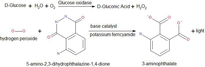
07/25/2016 at 17:49 • 3 commentsIf we want to produce our own glucose test strips, we need glucose oxidase. I have still no clue where to buy glucose oxidase or if I will be able to produce it by myself (extracted from the fungus Aspergillus niger?), but I came up with a glucose oxidase detection reagent in the mean time. The idea is as following:
![]()
Unfortunately I run out of test strips, so I need to buy more to pursue my idea of a glucose oxidase detection reagent.
-
Open source glucose meter code
07/23/2016 at 11:48 • 1 comment// open source glucose meter code, version 1 int strip_detect = 2; int current = 0; // measurement starts if transimpedance amp output voltage > threshold float threshold = 2.8; #include <Wire.h> #include "RTClib.h" RTC_Millis RTC; void setup() { Serial.begin(9600); // set the RTC to the date & time this sketch was compiled RTC.begin(DateTime(__DATE__, __TIME__)); pinMode(strip_detect, INPUT); } void loop() { while(1) { if(digitalRead(strip_detect) == 1) break; } Serial.println("APPLY BLOOD"); float current_voltage; while(1) { current_voltage = analogRead(0) * (5.0 / 1023.0); if(current_voltage > threshold) break; } // count down timer for(int i = 5; i > 0; i--) { delay(1000); Serial.print(i); if(i > 1) Serial.print(", "); else Serial.println(""); } // compute concentration current_voltage = analogRead(0) * (5.0 / 1023.0); float concentration = 495.6 * current_voltage - 1275.5; Serial.print(concentration); Serial.println(" mg/dL"); display_time(); while(1) { if(digitalRead(strip_detect) == 0) break; } delay(1000); //debounce } void display_time() { DateTime now = RTC.now(); Serial.print(now.year(), DEC); Serial.print('-'); Serial.print(now.month(), DEC); Serial.print('-'); Serial.print(now.day(), DEC); Serial.print(' '); Serial.print(now.hour(), DEC); Serial.print(':'); Serial.print(now.minute(), DEC); Serial.print(':'); Serial.print(now.second(), DEC); Serial.println(); } -
Measurement series
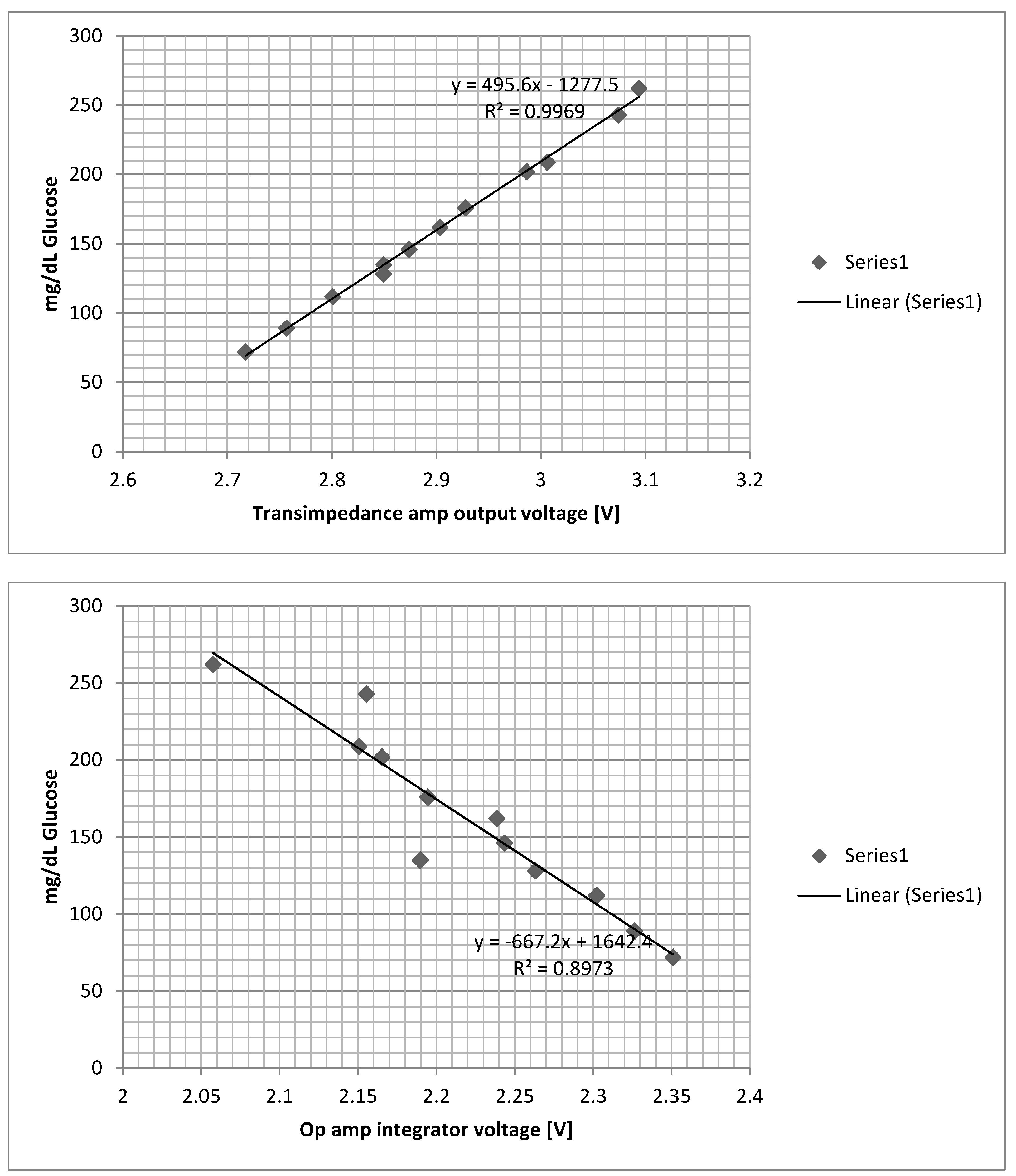
07/23/2016 at 10:06 • 1 commentToday I started a measurement series by preparing control solutions with different glucose concentration, measuring the concentrations with the commercial glucose meter and comparing the results with the measured transimpedance amp and op amp integrator output voltage of my DIY glucose meter. I used Excel scatter charts to apply linear regression.
Test code:
int current = 0;
int integral = 1;
float threshold = 2.8;

void setup() {
  Serial.begin(9600);
  pinMode(6, OUTPUT);
}

void loop() {
  float current_voltage = analogRead(0) * (5.0 / 1023.0);
  float integral_voltage = analogRead(1) * (5.0 / 1023.0);
  if(current_voltage > threshold) {
    // reset integrator
    digitalWrite(6, HIGH);
    delay(100);
    digitalWrite(6, LOW);
    //delay 5 seconds like the ONE TOUCH ULTRA 2
    delay(5000);
    current_voltage = analogRead(0) * (5.0 / 1023.0);
    integral_voltage = analogRead(1) * (5.0 / 1023.0);
    Serial.print("Current to voltage: ");
    Serial.println(current_voltage,5);
    Serial.print("Integral to voltage: ");
    Serial.println(integral_voltage,5);
    while(1);
  }
}
Scatter charts:
As we can see the relation between the glucose concentration and the transimpedance amp output voltage is nearly linear. We can obtain following formula for computing the glucose concentration by the transimpedance amp output voltage:![]()
-
Synthesizing the control solution
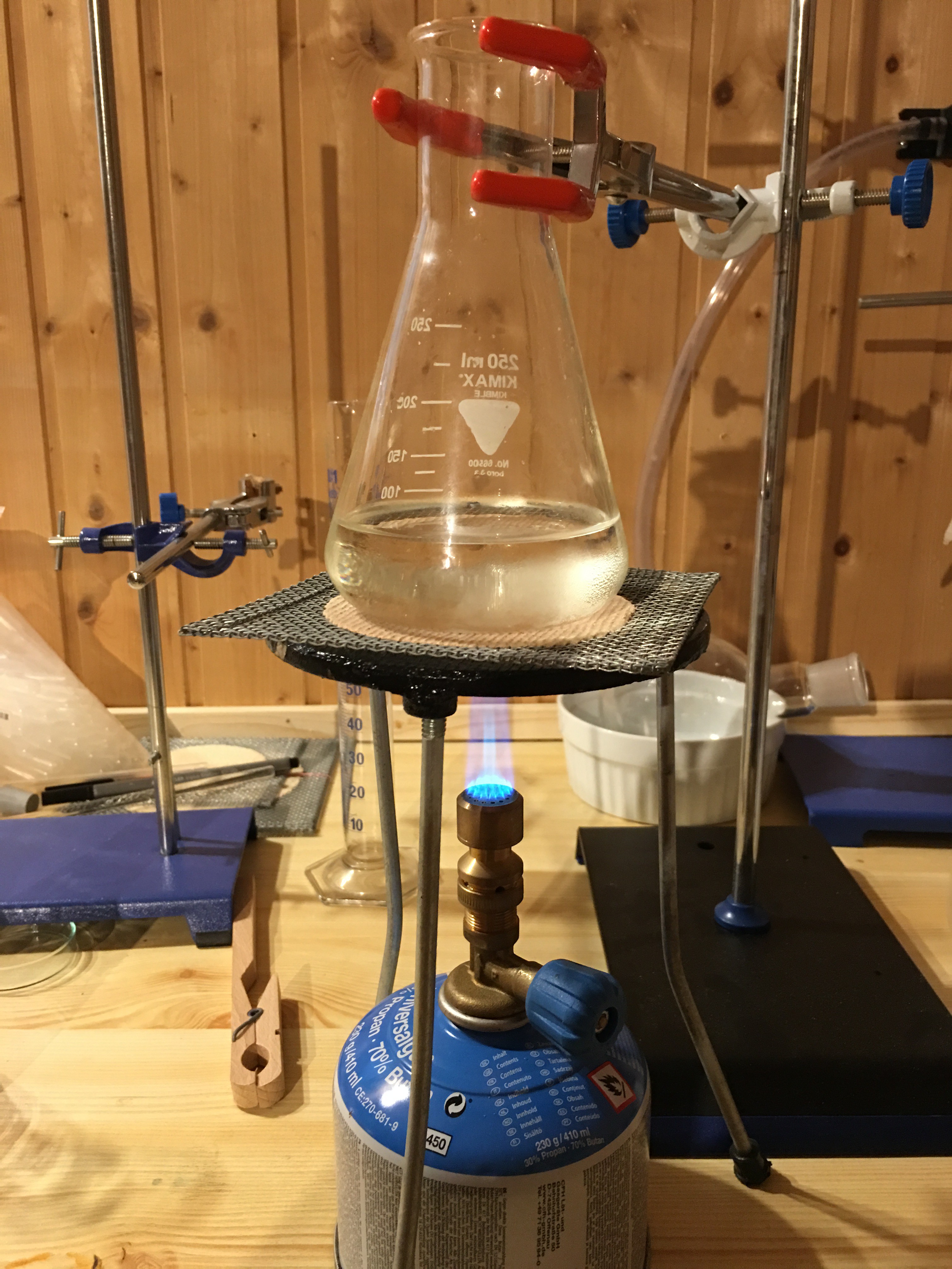
07/16/2016 at 14:29 • 1 commentToday all necessary chemicals arrived, so I started to synthesize the ONE TOUCH ULTRA control solution. I used:
- Deionized water
- Polyvinylpyrrolidone
- Sodium benzoate (min. 99%, Ph. Eur., BP, FCC, LM)
- EDTA (disodium salt)
- D(+)-Glucose (chemically pure)
- Indigo carmine (I was not able to purchase Amaranth)
Firstly I prepared a solution of 91ml deionized water, 8g polyvinylpyrrolidone, 0.5g sodium benzoate and 0.5g EDTA (disodium salt). As the EDTA (disodium salt) did not dissolve completely under room temperature I heated the solution up to approx. 50°C and stirred it frequently.
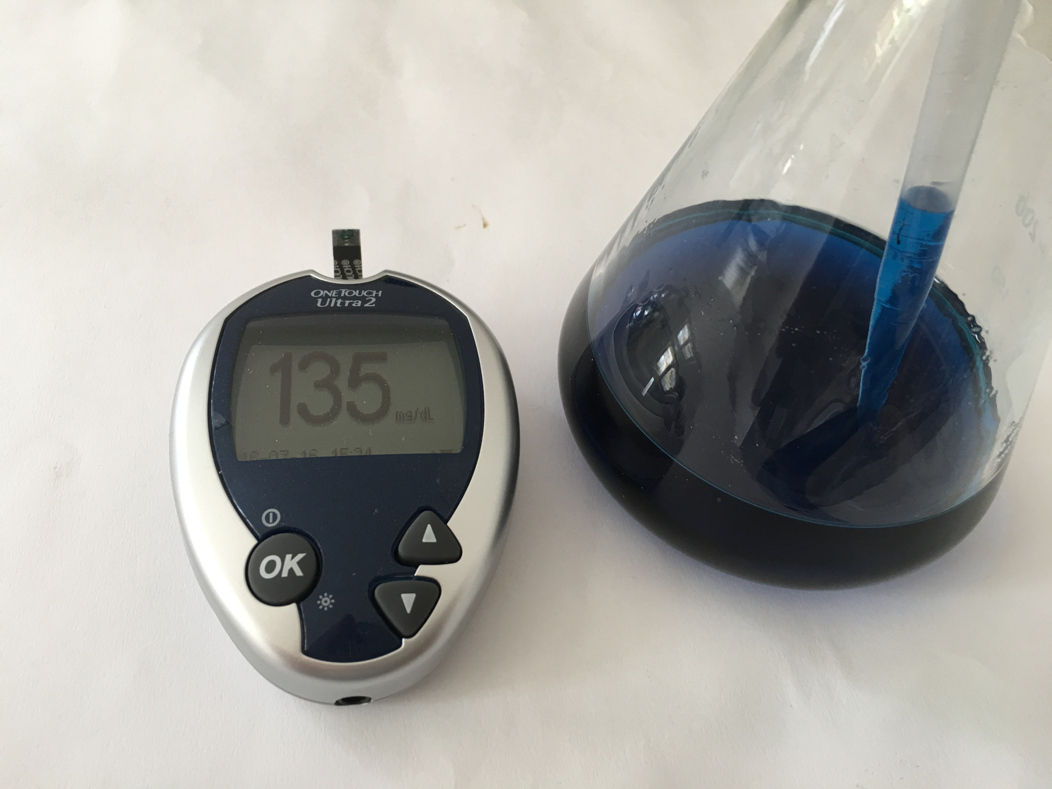
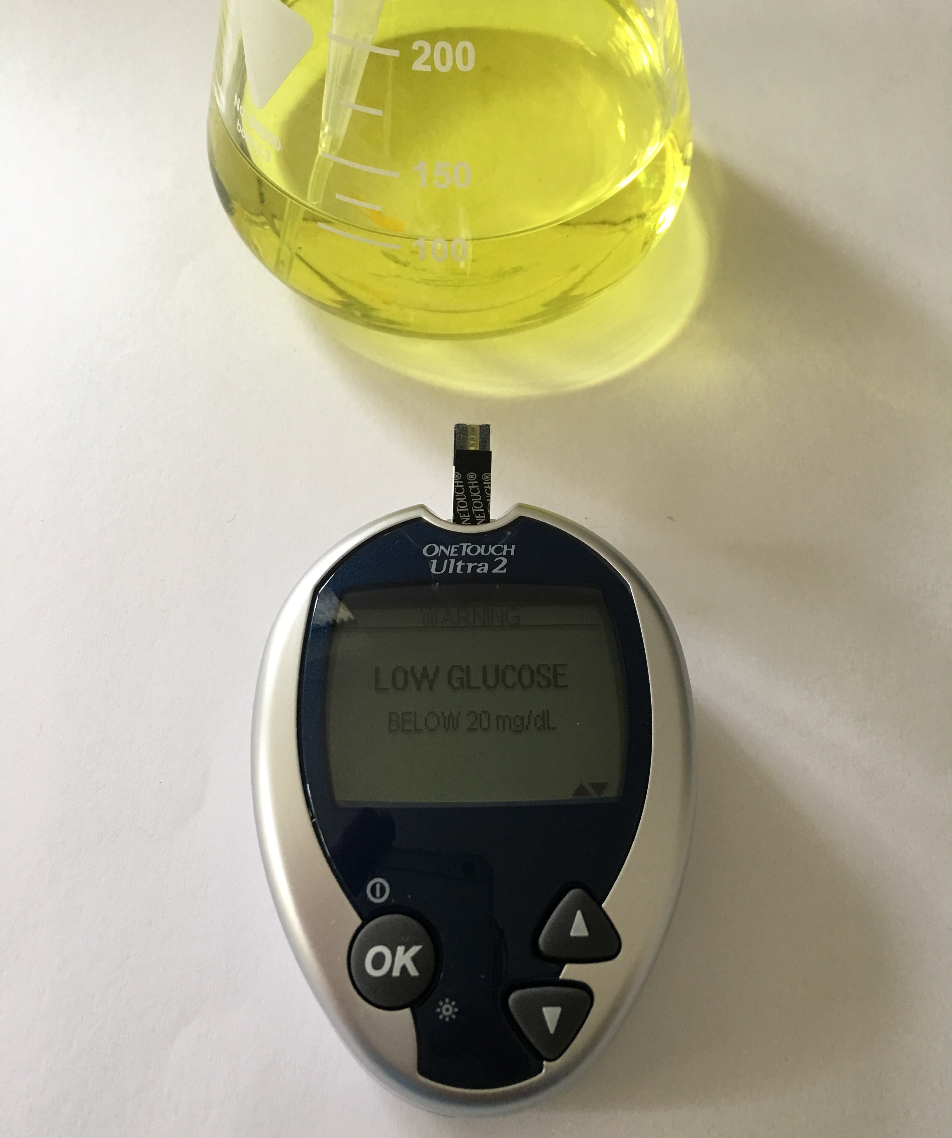
After the EDTA was completely dissolved the solution was allowed to cool down to room temperature again. After that one pinch of indigo carmine was added. The solution had now a volume of exactly 100ml. Then I dissolved 0.12g glucose and expected that the glucose meter would show approx. 120mg/dl, which wasn't the case. The glucose meter displayed: WARNING. Below 20 mg/dL. LOW GLUCOSE.![]()
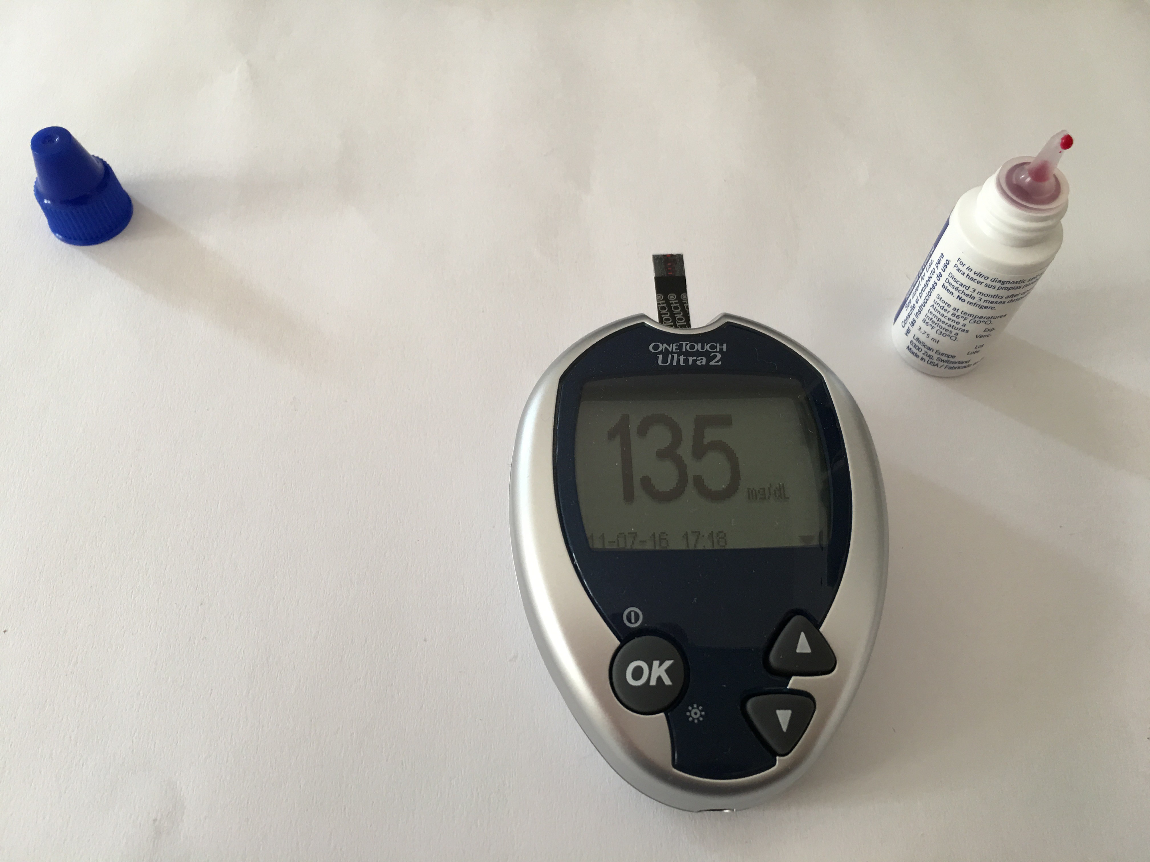
I added 0.38g glucose more to the solution. Now I got a proper reading: 135mg/dl, same as the original control solution.
Conclusion: The glucose meter does not read the real glucose concentration of the control solution. In the end it doesn't matter. I can prepare different control solutions by adding small amounts of glucose, compare the result of the commercial glucose meter with the results of my home brew one and find a mathematical dependence between the results.![]()
Summarized: A control solution similar to the ONE TOUCH ULTRA one can be prepared by dissolving 8g polyvinylpyrrolidone, 0.5g sodium benzoate, 0.5g EDTA (disodium salt), 0.5g D(+)-Glucose and additionally a pinch of indigo carmine in 91ml deionized water.
-
Blood is thicker than water
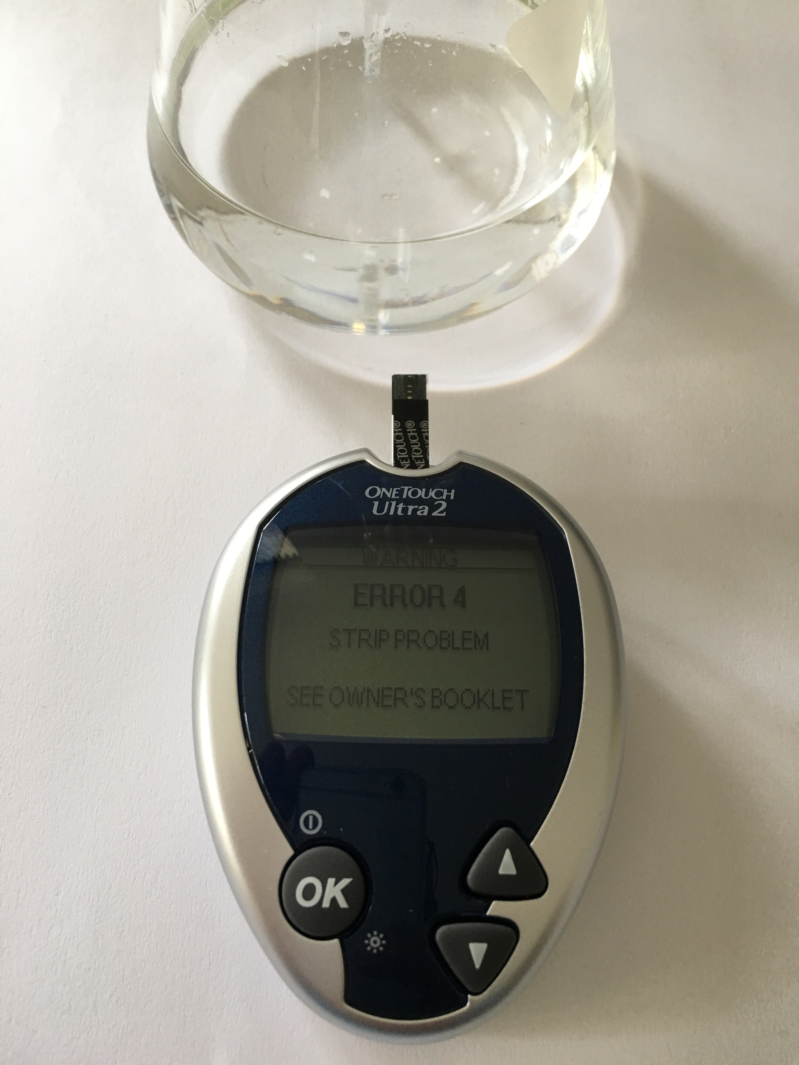
06/12/2016 at 12:51 • 6 commentsToday I tested the commercial ONETOUCH ULTRA 2 blood glucose meter. I prepared a solution of 100mg D-(+)-Glucose/dL distilled water to test the meter. But the meter didn't recognize the aqueous glucose solution. Always the same ERROR 4 occurred:
Obviously the electrochemical process does not start with a pure aqueous glucose solution. I tried to prepare some kind of artificial blood by adding 1g potassium ferricyanide to the glucose solution. Now I got readings, but much lower than the actual glucose concentration of the solution:![]()
![]()
Update:
According to the suggestion of Ryan Bailey I prepared a solution of 0.9g NaCl and 100mg glucose per 100ml distilled water. Result again ERROR 4:
I think the reason why potassium ferricyanide worked in the test solution is because potassium ferricyanide is used in many amperometric biosensors as an electron transfer agent replacing an enzyme's natural electron transfer agent such as oxygen as with the enzyme glucose oxidase. Potassium ferricyanide is also used as a blood replacement and catalyst for the chemiluminescence demonstration of luminol.![]()
Next step: I will try to analyze the glucometer calibration solution.
The ONE TOUCH ULTRA control solution has a blood-red color. No ingredients are mentioned on the bottle. On the instruction leaflet is mentioned that the control solution consists of glucose in water (about 0.11%) with buffers and stabilizers, a viscosity adjusting agent, a preservative, and a red dye.
The glucose meter shows a concentration of 135mg glucose/dl.
![]()
-
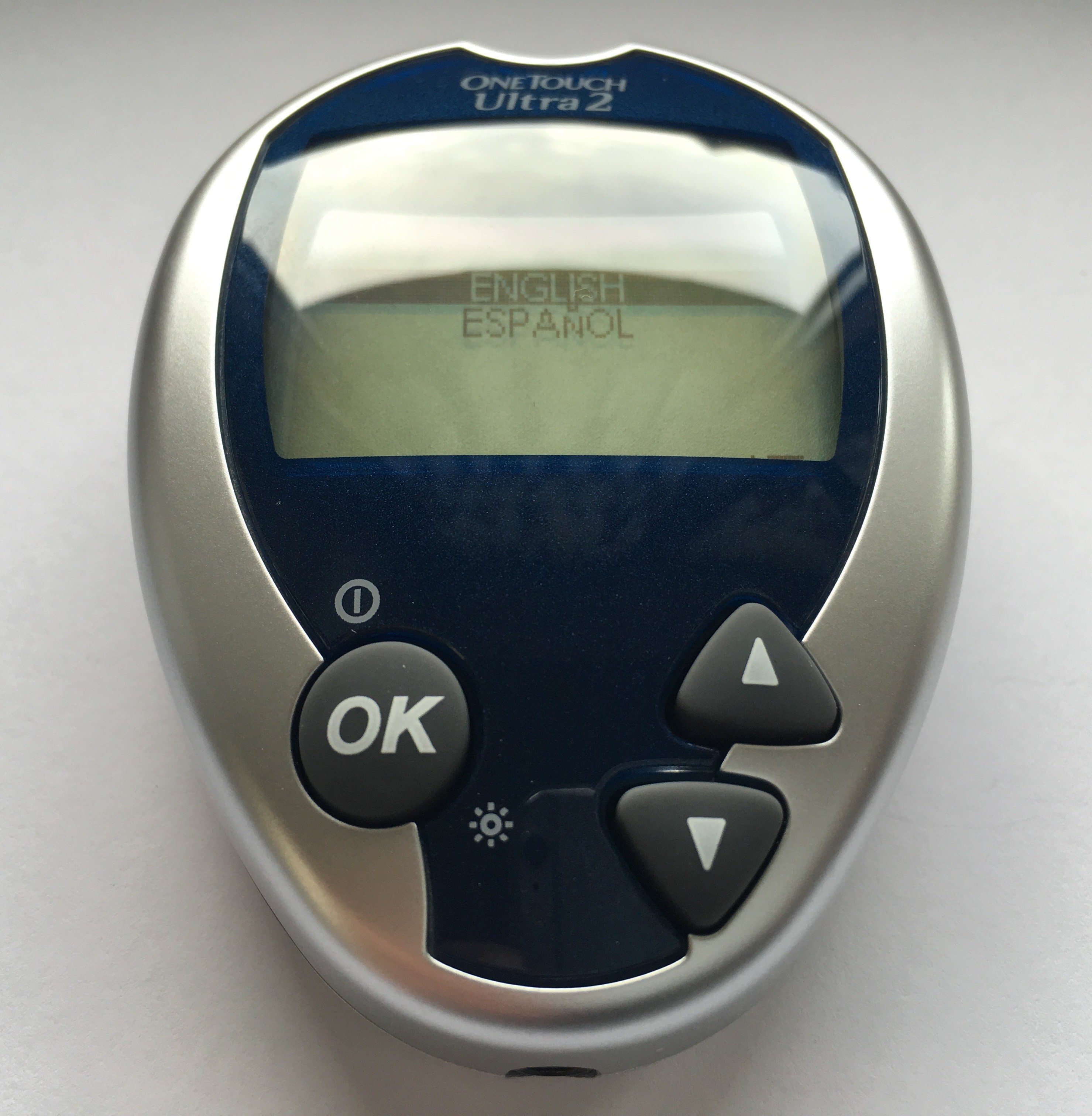
Reference blood glucose meter
06/08/2016 at 16:08 • 0 commentsI purchased a ONETOUCH ULTRA 2 blood glucose meter for reference measurements to calibrate the Arduino blood glucose meter.
![]()
-
PCB design
06/05/2016 at 11:55 • 0 commentsThe shield has an Arduino Uno form factor. I changed the MAX4575, which resets the op amp integrator by shortening the capacitor by the quad bilateral switch CD4066, because this chip is much cheaper. Initial PCB layout looks as follows:
![]()
Checking if the test strip connector footprint I have drawn matches...
![]()
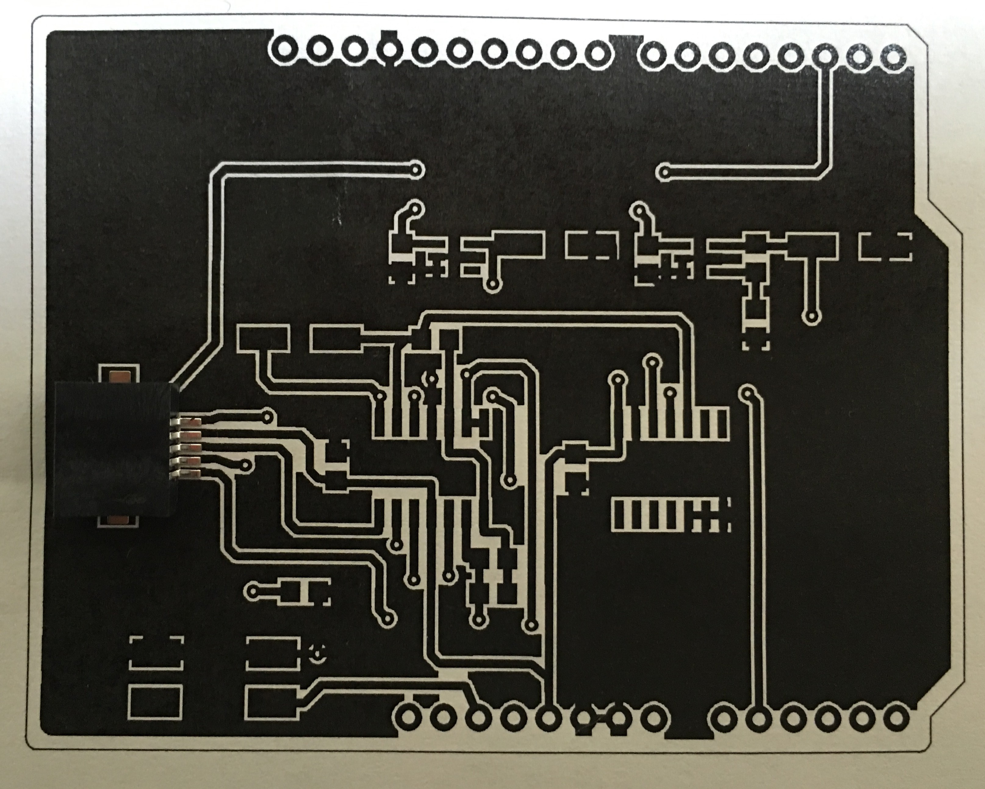
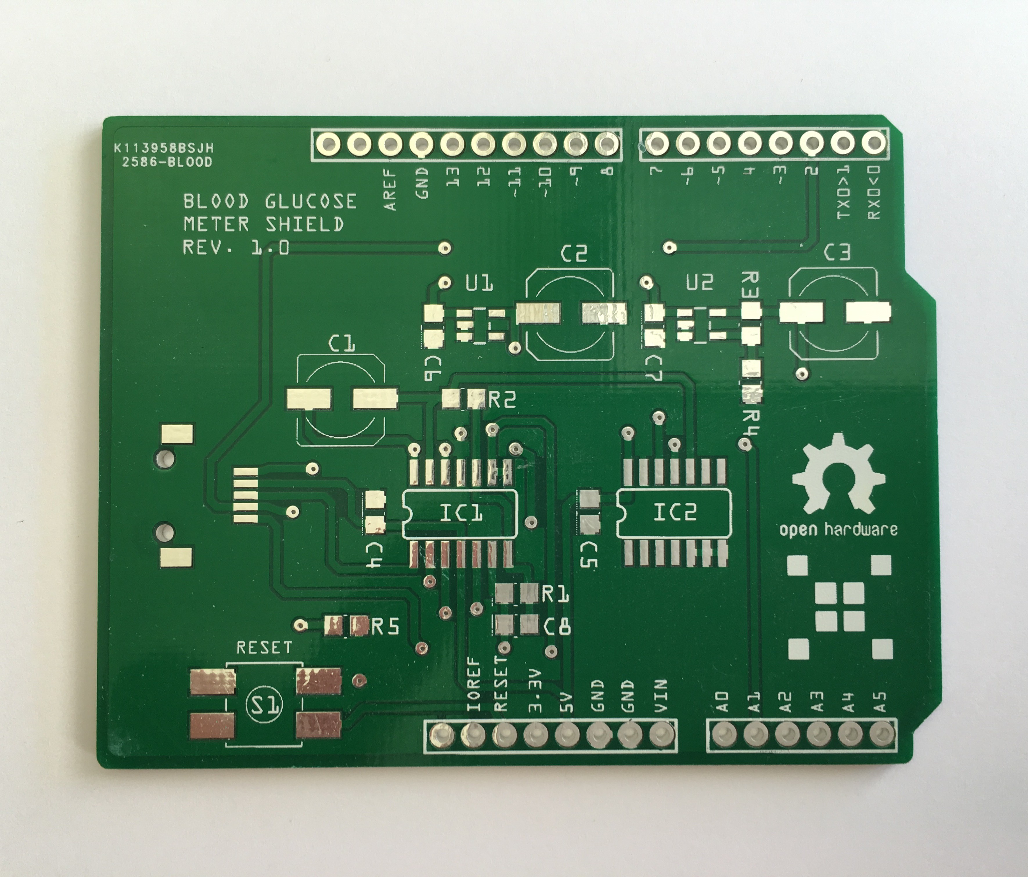
Blank PCB:
![]()
Populated board, ready for testing:
![]()
-
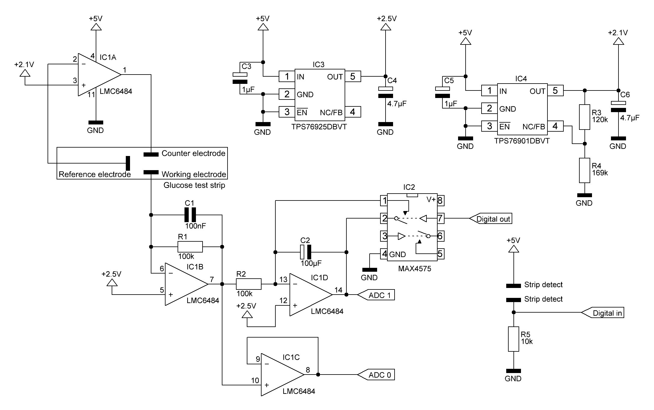
Basic glucose meter schematic
06/02/2016 at 19:06 • 8 commentsHere is the first draft of the glucose meter schematic:
Mathematically interesting is only the op amp integrator (IC1D). The formula for determining voltage output for the integrator is as follows:![]()
As the non-inverting input is not connected to GND (VR = 0V) but to VR = +2.5V:
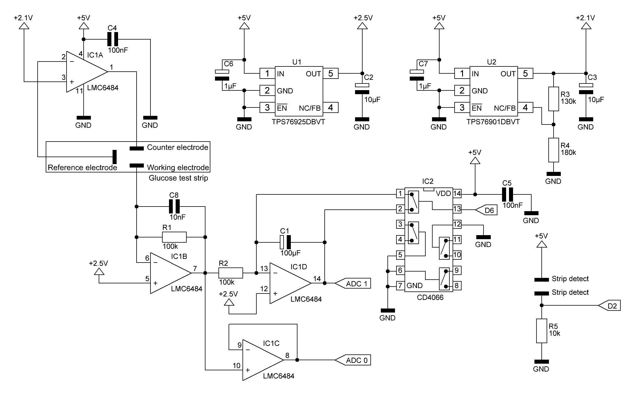
Updated schematic:
![]()
I changed the MAX4575, which resets the op amp integrator by shortening the capacitor by the quad bilateral switch CD4066 (IC2), because this chip is much cheaper. Because integration involves a known start time and end time, a reset circuit must be included to establish the start time before each integration time period. The integration end time occurs when the measurement is read. The CD4066 simply short-circuits the capacitor C1 if digital output D6 goes HIGH. The not used control inputs are tied to ground. Unused CMOS input pins must never be unconnected, because they tend to float towards the dangerous region which is in the middle between VDD and GND.
The low-dropout regulator TPS76925DBVT (U1) provides a fixed output voltage of 2.5V.
The output voltage of the TPS76901 adjustable regulator (U2) is programmed using an external resistor divider. The output voltage is calculated using:
Where: Vref = 1.224V typ (the internal reference voltage).
As the applied voltage across two of the test strip electrodes should be about 400 mV, I chose R3 = 130k and R4 = 180k which results in a TPS76901 output voltage of 2.108V.
As mentioned above IC1D is configured as an op amp integrator. Currently I don't use the op amp integrator because the op amp integrator output voltage is not directly or indirectly proportional to the glucose concentration when using ONETOUCH test strips. This might be the case when using other test strips.
IC1B is configured as a transimpedance amplifier, where basically
The feedback capacitor C8 is required to improve stability.
IC1A and IC1C are configured as unity gain buffer amplifiers. In this configuration, the entire output voltage is fed back into the inverting input. The difference between the non-inverting input voltage and the inverting input voltage is amplified by the op-amp. This connection forces the op-amp to adjust its output voltage simply equal to the input voltage:
For IC1A this is only the case if an electrolytic bridge (blood) between the reference and counter electrode is applied.
As long as the strip is not inserted, input pin D2 is LOW. If a test strip is inserted, the two strip detect pins on the strip connector getting connected and D2 goes HIGH.
C4 and C5 are decoupling capacitors.
Open source Arduino blood glucose meter shield
Open hardware and software blood glucose meter using electrochemical test strips