Johan Berglund
-
Part 5: Casio 2nd octave modification
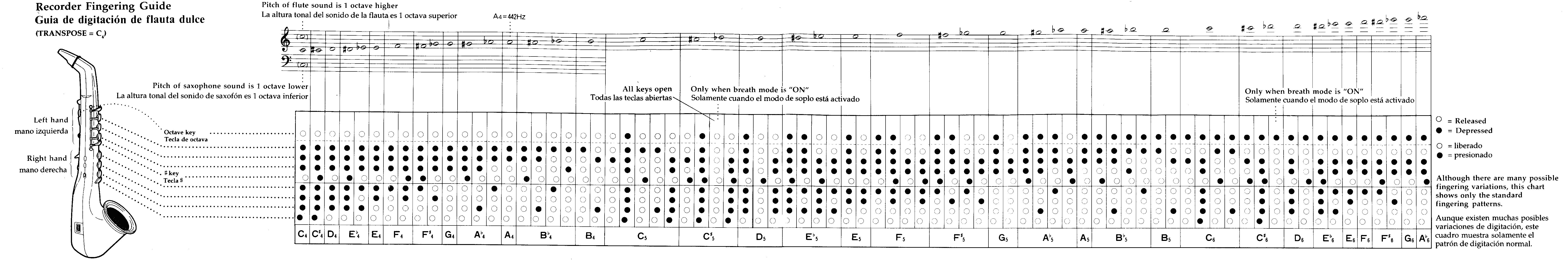
05/31/2016 at 11:13 • 0 commentsI was considering ripping the guts out of my broken Casio DH-200 Digital Horn and replacing them with a MiniWI circuitry. Keeping the octave switching as is would be very limiting if using the reduced EWI fingering of the MiniWI, so I had another look at the Casio fingering chart because I had a vague recollection of some differences in the higher note fingerings.
![]()
Actually, it turned out to be like this – if LH1 isn't pressed while LH2 and LH3 are, you play the 2nd octave. For example LH2+LH3+RH1 would be F in the 2nd octave. To make this work with the existing fingering formula I had to change the conditions for the bis key, removing LH1 from that part, otherwise the bis key would affect the Casio fingerings. Don't see any drawbacks in doing that so far.
So, what I did was to put a define in the beginning of the code for easy choosing between the EWI or the Casio modified fingerings...
#define casioMod 1 // Extra notes on top Casio DH style...then I replaced the calculation in the readSwitches function with this:
//calculate midi note number from pressed keys
if (casioMod){
    fingeredNote=startNote-2*LH1-(LHb && !LH2)-LH2-(LH2 && LH1)-2*LH3+LHp1-LHp2+(RHs && !LHp1)-RH1-(RH1 && LH3)-RH2-2*RH3+RHp1-RHp2-2*RHp3+12*OCTup-12*OCTdn+9*(!LH1 && LH2 && LH3);
} else {
    fingeredNote=startNote-2*LH1-(LHb && !(LH1 && LH2))-LH2-(LH2 && LH1)-2*LH3+LHp1-LHp2+(RHs && !LHp1)-RH1-(RH1 && LH3)-RH2-2*RH3+RHp1-RHp2-2*RHp3+12*OCTup-12*OCTdn;
}
Seems to work just fine. It will probably be a very nice addition when I build the touch key control only TeensieWI later on. And of course a given should I decide to modify my broken Casio horn.
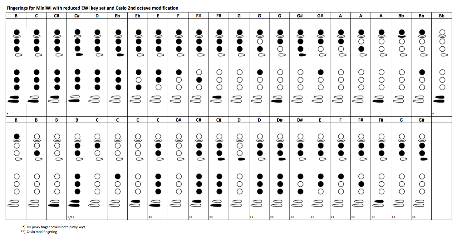
I put together a chart with the most useful fingerings including the new Casio fingerings using Bret Pimentel's Fingering Diagram builder:
![]()
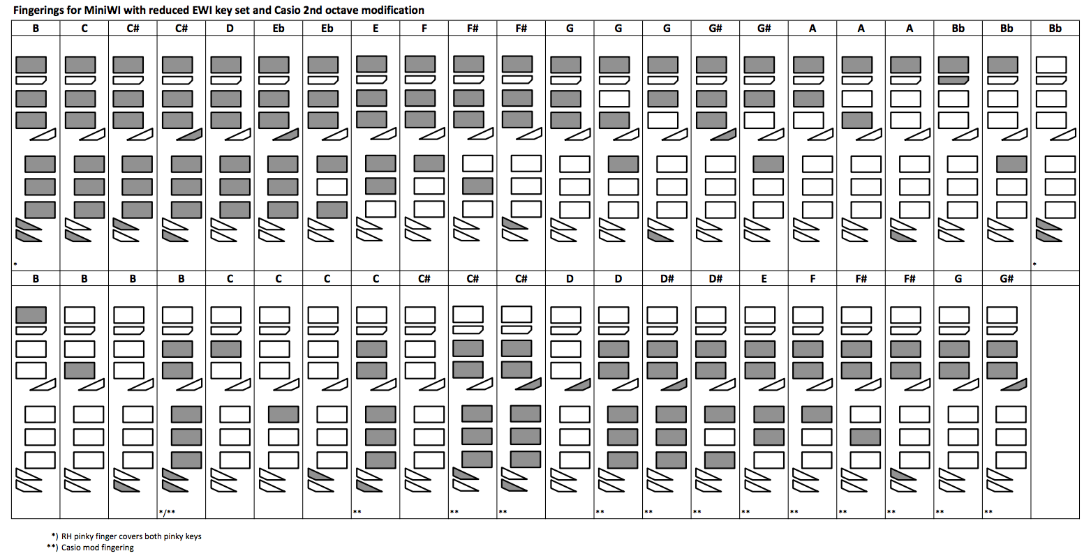
Also made a chart more representative of the MiniWI look. Less friendly to the eyes? I don't know... putting it here anyways.
![]()
If you note the look of the pinky finger keys is different from before, this is how they will look in the next prototype. I'm wrapping them around the other side and cutting them shorter to avoid accidentally touching LH pinky key with my right hand.
The fingering changes have been added to the MiniWI-cap-pmt.ino on Github. -
Part 4: Ideas for further development
05/25/2016 at 10:52 • 0 commentsAlong the way several ideas have popped up, and some of them I'm very likely to explore. These are:
• A TeensieWI using the built in touch sense of the Teensy LC. This would also use the built in USB MIDI compatibility of the Teensy, and also draw power from the USB. I would use only touch keys and no joysticks or potentiometers, making this controller incredibly small. Thinking of sandwiching the components between two UV reactive translucent perspex sheets and put some UV/purple LEDs inside... just for the cool look :) More MPX5010GPs and a Teensy LC already ordered... :)
• A MiniVI, as in Valve Instrument, based on the EVI1000 and the Steiner MIDI EVI. Already begun writing the firmware for this.
• Built in sound capabilities. Possibly as a snap-on module for the MiniWI. I've bought a clever little MIDI synth chip programmed by fellow Swede Jan Östman, the dsp-G1. No problem to fit inside the already cramped MiniWI housing. Also got some small 5V amp boards and a variety of tiny speakers to work with.
• Instead of conductive tape, make metal inlays in the wood. A bit more work, but could look awesome.
• DIY kits? Maybe, if people want them.
-
Part 3: Evaluation and modification
05/24/2016 at 19:47 • 0 commentsIn general, the playable prototype was a success! Fingers fell naturally on the touch pads with only three minor instances where the pads should be altered or moved. One was the bis key between LH1 and LH2, where the LH2 finger would go across the bottom corner of the bis pad. This was easily solved with an x-acto knife. Another problem was the LH pinky key being a bit to close to RH1. Slight risk for glitching there. To be solved in later versions. Not too big a problem at the moment. Then there was a minor issue with the RH pinky keys being a bit too close to each other. This was mainly caused by one of the pads being a tad too big. Also solved with the x-acto.
The choice of copper tape had an obvious backside to it – the oxidation. Using aluminium tape instead, or in combination with copper, could be a good alternative. I've also been looking at making metal inlays in the wood.
Playability with the breath was no problem, as that was already tuned well from the breadboard prototype. Pitch bend and modulation joystick was also very well placed and it felt natural to use. Pitch bend needed to be scaled down a bit though, so I added a pitch bend sensitivity parameter in the firmware. With the present setting it will go only 50% of the value for full pitch bend. Much better.
Octave shifting was not as easy to play as I had hoped. Using both X and Y of the joystick to control the octaves got kind of weird. I often slipped to the sides during play, and the sideways motion was generally not as intuitive as the up and down motion that on the other hand felt very similar to using the octave rollers on the "real" EWI. I decided to fix this by disabling the sideways motion and putting in a potentiometer for setting the base octave in five steps (-2 to +2) instead. This way I would get a wider range for the controller in total, but a more narrow range instantly accessable during play.
A feature I realized was missing was control for portamento (glide), and as there was an unused analog input on the Pro Mini and unused inputs on the MPR121 board I could easily add a potentiometer for portamento rate setting and a touch pad by the mod stick at the same time as I did the octave stick modifications. When adding these new features in the firmware I also changed the playing mode to legato when changing fingering while a note is already playing. That means the new note gets a MIDI note on before the old one gets a MIDI note off. This of course to make the portamento work. So far there have been no issues playing my wind controller patches with this change, but there might be instances where the legato mode could use a disable function. Might look into that later.
![]()
The firmware now feels pretty final, and the controller hardware is actually really nice to play! It is so light (200 grams) and small (300x40x35 mm for the main body) it feels more like playing a recorder than an EWI, and now when I switch to the EWI... well the EWI feels like an elephant in my hands :) I can without hesitation say: mission accomplished! :D
-
Part 2: The playable prototype with touch keys
05/24/2016 at 11:06 • 0 commentsAfter a failed attempt to create a compact board with moving keys and switches, I got another push in the right direction by the Gordophone blog. Gordon had just published an example using capacitive touch switches, and of course I had to try that.
I adapted my design and firmware for use with the Adafruit MPR121 capacitive touch sensor breakout board. At the same time I reduced the key setup a bit by removing keys I never or rarely use, just to get the instrument more compact and somewhat simplified. For a recorder or flute player moving to EWI this would still be a good setup.
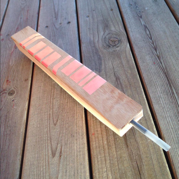
I cut the keys from adhesive copper tape (to my surprise marketed as anti-slug tape!) mounted them on my piece of oak with one end of the tape wrapping over the edge to the backside where I soldered in connection wires to the MPR121 board.
With the hand placing marked out like that, I could proceed with the placement of joystick controllers for octave, pitch bend and modulation, putting them where my thumbs ended up and securing them with small wood screws (the kind that comes with micro servos).
Then there was the matter of fitting everything else on the board, leaving some room on the sides for some 2 mm plywood walls.
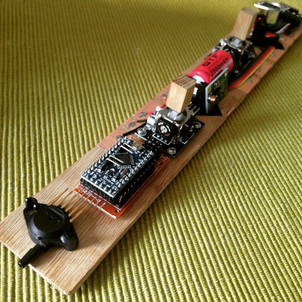
![]()
A bit tight, but it would work. The Pro Mini got a nice placement in front on a piece of perfboard with screw holes and soldered in headers for all the inputs plus a bunch of extra VCC and GND pins in the back.
Frontmost I put the pressure sensor, for connection directly to a silicone tube mouthpiece. I kept the closed system (no air flowing through the instrument) as that proved to work very good. I actually prefer it over the flow through system in the EWI.
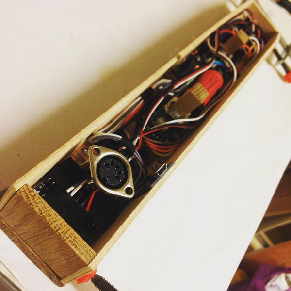
In the back with the MPR121 board there was some free space for the connectors (MIDI jack and Micro USB charge board), and the battery plus the 5V step-up boost converter board were squeezed in between the joysticks.
![]()
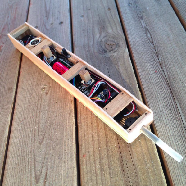
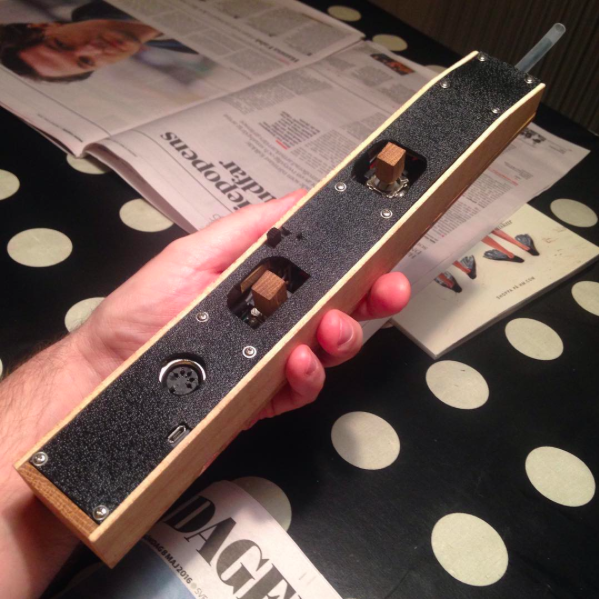
With the wiring in place I could still fit the plywood sides, so that was a success :) So, I just glued the housing together with some support bars and made a bottom for it. With removal of the two frontmost screws, the bottom could be pried open enough to connect the programmer to the Pro Mini for firmware updates.
![]()
![]()
![]()
The playable prototype controller was completed! Time for evaluation! :)
-
Part 1: The breadboard prototype
05/23/2016 at 11:02 • 0 commentsI started with very basic solutions. The only fancy component was the Freescale MPX5010GP pressure sensor. The rest was just switches and potentiometers (while waiting for the joysticks I was planning to use). From all the available pressure sensors on the market I went with the MPX5010 based on what other people had been using for the same purpose, and the GP version for the side mounted tube connection, the practical housing with screw holes and the through hole pins that could also be used with Dupont connector cables.
The Arduino Pro mini would allow me to connect enough switches and potentiometers to recreate the EWI key set and some controls for octave, pitch bend and modulation, so I could stick to my plan there. Small size, low cost.
For writing the firmware I first had a look at the page of Tom Scarff, midikits.net. I had ordered some stuff from him years ago and I remembered he had some examples on how to send MIDI with Arduino. I found he had also made wind controllers, and I had a look at his midi trombone code. It was rudimentary at best, so I just borrowed the midi routines and the comment style and figured I'd write the rest myself. I had a pretty good idea in my head how it should all come together, so I went ahead.
My main concern was how to work out the decoding of the fingering. Most people seemed to use switch case functions where all thinkable fingering combinations were listed, but knowing my EWI I thought that could not be how the decoding was made. It seemed more like there were logical conditions for each individual key. Looking around a bit for answers I found the blog of Bret Pimentel and his post on flexible EWI fingerings.
He had it all figured out. Each key changes the note value a certain number of semitones up or down, some of them with conditions. Let's list them here as variable declarations for the Arduino sketch:
// Key variables, TRUE (1) for pressed, FALSE (0) for not pressed
byte LH1;  // LH key 1 (pitch change -2)
byte LHb;  // LH bis key (pitch change -1 unless LH1 and LH2 are pressed)
byte LH2;  // LH key 2 (with LH1 pressed pitch change is -2, else -1)
byte LH3;  // LH key 3 (pitch change -2)
byte LHp1; // LH pinky key 1 (pitch change +1)
byte LHp2; // LH pinky key 2 (pitch change -1)
byte RHs;  // RH side key (pitch change -2 unless LHp1 is pressed)
byte RH1;  // RH key 1 (with LH3 pressed pitch change is -2, else -1)
byte RH2;  // RH key 2 (pitch change -1)
byte RH3;  // RH key 3 (pitch change -2)
byte RHp1; // RH pinky key 1 (pitch change +1)
byte RHp2; // RH pinky key 2 (pitch change -1)
byte RHp3; // RH pinky key 3 (pitch change -2)
byte OCTup; // Octave switch key (pitch change +12)
So all that needed to be done was to get the TRUE or FALSE values from reading the switches into those variables and make those conditions work in C code to add or subtract from the MIDI note number stated as startNote. In this case it is C#-3 with note number 61, the note playing if no keys are pressed on the controller.fingeredNote=startNote-2*LH1-(LHb && !(LH1 && LH2))-LH2-(LH2 && LH1)-2*LH3+LHp1-LHp2+(RHs && !LHp1)-RH1-(RH1 && LH3)-RH2-2*RH3+RHp1-RHp2-2*RHp3+12*OCTup;Now, that was it! I had confidence in this now and went ahead full steam :)After wiring everything up on a breadboard and trying the controller out I realized most stuff was working just as I wanted it to, but there were serious issues with my main loop making notes stick and whatnot.
Trying to make the flow work, I did some additional internet searches on the matter and then I found the Gordophone blog by Gordon Good.
His step by step instructions on how to make Teensy/Arduino wind controllers included a very easy to follow state machine flow for the main loop. It seemed perfect, so I just inserted my code in his state machine and it all worked! I was thrilled, and immediately contacted him to say thanks and to let him know. I also wanted to share my thoughts on fingering to note calculation with him. He was very glad to hear from me, and he asked me If I would like to write a guest post about it on his blog. That sounded like fun, so I did.
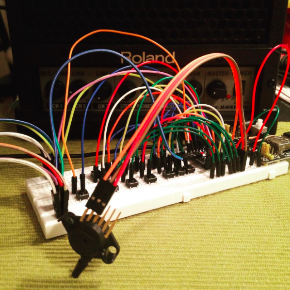
So... finally I had a working breadboard prototype, and it looked like this:
To see it in action, go to...![]()
https://www.instagram.com/p/BEN1oIuoVba/?taken-by=trasselfrisyr
and..
https://www.instagram.com/p/BES5hIPIVdv/?taken-by=trasselfrisyr
...and yeh, Instagram is where I've kept people updated on my progress along the way. You should really check it out :)
https://www.instagram.com/trasselfrisyr/
The firmware for this state of the project is still available for reference.
MiniWI woodwind MIDI controller
Small and light Arduino Pro Mini based wind controller with DIN-5 MIDI output and fingering based on the AKAI EWI.