-
Modifying OctoWS2811 to work with RGBW led strips
06/12/2016 at 23:37 • 1 commentWhen using these single data line led strips a problem arises when using hundreds (or more) leds off a single data line. The 800kHz signal is too slow to update all the leds at a high framerate. The way to get around this is driving strips in parallel which is what products like the Fadecandy or the software OctoWS2811 for Teensy solve.
However, both of these solutions are currently only compatible with rgb strips (24 bits per pixel) so I had to modify OctoWS2811 to work with rgbw (32 bits per pixel). It was a pretty simple modification of using a variable to set the bits per pixel instead of a hard coded value of 24, as well as adding a way to convert from RGBW to GRBW which my strips were wired as. I renamed the library to OctoSK6812 since I took out the compatibility with 400kHz strips, and to differentiate from the official release of OctoWS2811 since my additions might break things since it hasn't been fully tested. It's OctoSK6812 since that is the driver chip inside these new rgbw leds, and this chip is also found in the mini rgb single data line leds.
Here's the code:
https://gist.github.com/nocduro/f26f8dbdd156ad73955f8288b138ba83
And a slightly modified test example also from OctoWS2811:
https://gist.github.com/nocduro/9b15ba001f52465897c56ba58b9d4d26
This test lights up the first 4 pixels to help identify the arrangement of the colours for a particular strip. If the leds show as: RGBWW then the correct configuration is set.
This modified version should also still work with the rgb variants of the SK6812 driver chip.
-
More parts arrived
05/31/2016 at 05:50 • 0 commentsKinda at the last minute for the entrance into the anything goes part of the Hackaday prize so one more quick project log to qualify :O More better posts in the next week or so...
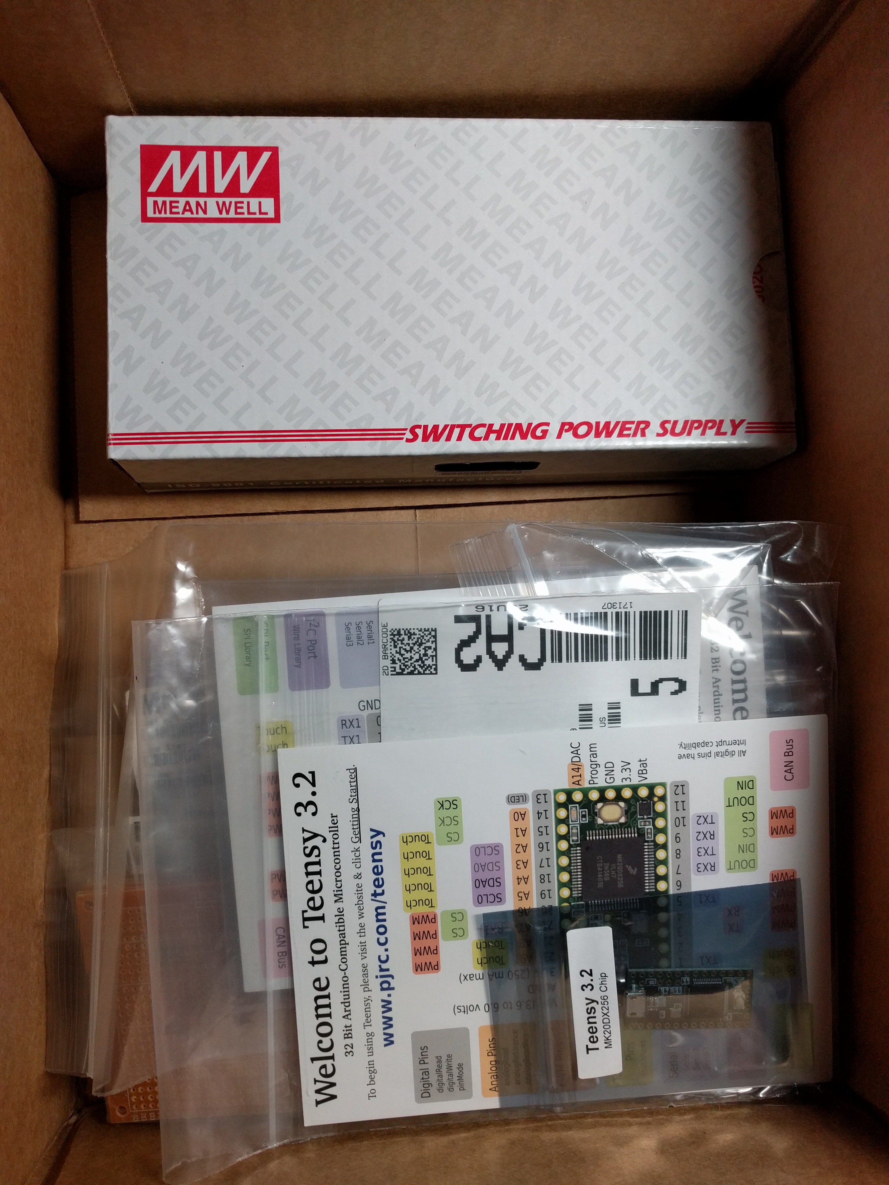
I got some more parts over the last week, mostly so I can start testing stuff to see what works.
- Couple of Teensy 3.2's so I can use one to test and embed the other in the project
- Meanwell 5V 26A power supply to test the led strips with a beefy supply
- Battery clips to build the battery holder
- Resistors to make voltage dividers to monitor battery pack state through balance connector
- Buffer chip to level shift 6 3.3V data lines to 5V to control leds
- and a little bit of bakelite protoboard
![]()
-
Design number 2
05/31/2016 at 05:41 • 0 commentsSo after the first idea didn't pan out I went back to the drawing board. One of the biggest problems was trying to fit the battery inside of the metal framework for the leds, and thanks to geometry if I add more sides that means I can decrease the outer radius. Basically lets me make the metal structure fit more tightly around the batteries as well as having more lights around them to hopefully get me 360 degree light distribution a little easier.
Looking at the current renderings right now you would notice that there is a large gap between the battery and the metal. This is to allow room for a 1" OD acrylic pipe which will make up the outer shell of the battery module. I have a 3D printer so I was thinking I could 3D print it instead to add things like cable management right into the holder. Another limitation is the width of the actual led strips. With the current model the sides of the hexagon are almost at their smallest possible size. I could move down to the smaller SK6812 strips which you can get in strips that are something like 3 or 4 mm wide(!) but those strips don't come in rgbw, and I wanted to get a nice pure white from the rod since it is meant to sorta emulate a fluorescent bulb.
The power delivery method also changed. Originally was using 3 LM2596 modules from ebay which could theoretically get me 9A with good heatsinking, but since I'm using 720 leds now I need a bit more power... I am instead going to use Pololu's 5V 9A buck regulators, probably 2 or 3 of them for either 18A max or 27A max output with good heatsinking. I also needed to up the batteries to 6 18650 cells. I might upgrade the batteries in the future as the ones I bought a while ago can only do 2C max (around 6-7A per cell in my case) and they are starting to be a limiting factor in the power section. I figure I can get around 90W out of the 6 batteries I have right now so 2 buck regulators would be enough, but I was thinking of future proofing in case I move to better batteries and with more regulators to share the load they wouldn't heat up as much individually.
Of course I haven't tested the thermals of all this stuff yet so I will probably be under driving the leds and regulators to save on heat output. That's probably the biggest issue/unknown right now.
-
Experimenting with diffusion material
05/23/2016 at 21:00 • 0 commentsThe end goal of this project was to emulate a standard fluorescent tube, and to do that the light coming off the tube would have to be very even. I tried a few different methods for diffusing with mixed results. Unfortunately I didn't take any pictures of the progress as they weren't working as well as I'd hoped...
Methods tried (so far):
- Sanding the outside of the acrylic tube
- Very thin coat of white paint
- Spray on frosted coating (Rustoleum type stuff)
- Under cabinet diffusers that are used in kitchens
This one probably worked the best, I sanded with I think 220 grit in multiple directions. I sanded length wise, radially, and then in kind of an angle. Maybe this combined with something else like tracing paper would work well.
Thin coat of white paint:
I was hoping this would give a fluorescent tube appearance and help in diffusion, but the light just ended up exposing every small imperfection in the paint job. The theory behind it was that maybe the white paint particles would give the light something to bounce off of and emulate actual diffusion material.
Spray on frosted coating:
Again, mixed results. Worked a little bit but I'm worried the coating isn't that durable, and when I tried putting a clear coat over top, the frosting effect disappeared...
Purpose made diffusers for strip lights:
Turns out stuff built exactly for your application works pretty well. Who would've thought eh? More seriously, this stuff worked fairly well with some modifications, but would need to be combined with another method to give a smooth 'white' exterior finish. Perhaps this and some tracing paper or diffusion film?
Other (untested) ideas:
Using diffusion film common in the sign industry. Can't find a supplier for this yet though :(
I also ordered some 140 degree 5050 led lenses from china that I was going to try and sand down to diffuse to see if that helped.
-
Initial idea
05/23/2016 at 20:46 • 0 commentsI didn't document as I was trying stuff out, so these first few entries are a recap of what I've done so far. Hopefully that's ok with the hackadayprize2016 rules :)
I was originally going to mount some APA102 all white addressable leds to some aluminum in a triangle to create the 360 degrees of light I wanted.
![]()
However, the aluminum touched the very edge of the tube so it wouldn't give perfectly even light all around. I also ran into some trouble programming the APA leds and put the project on hold for a while after this.
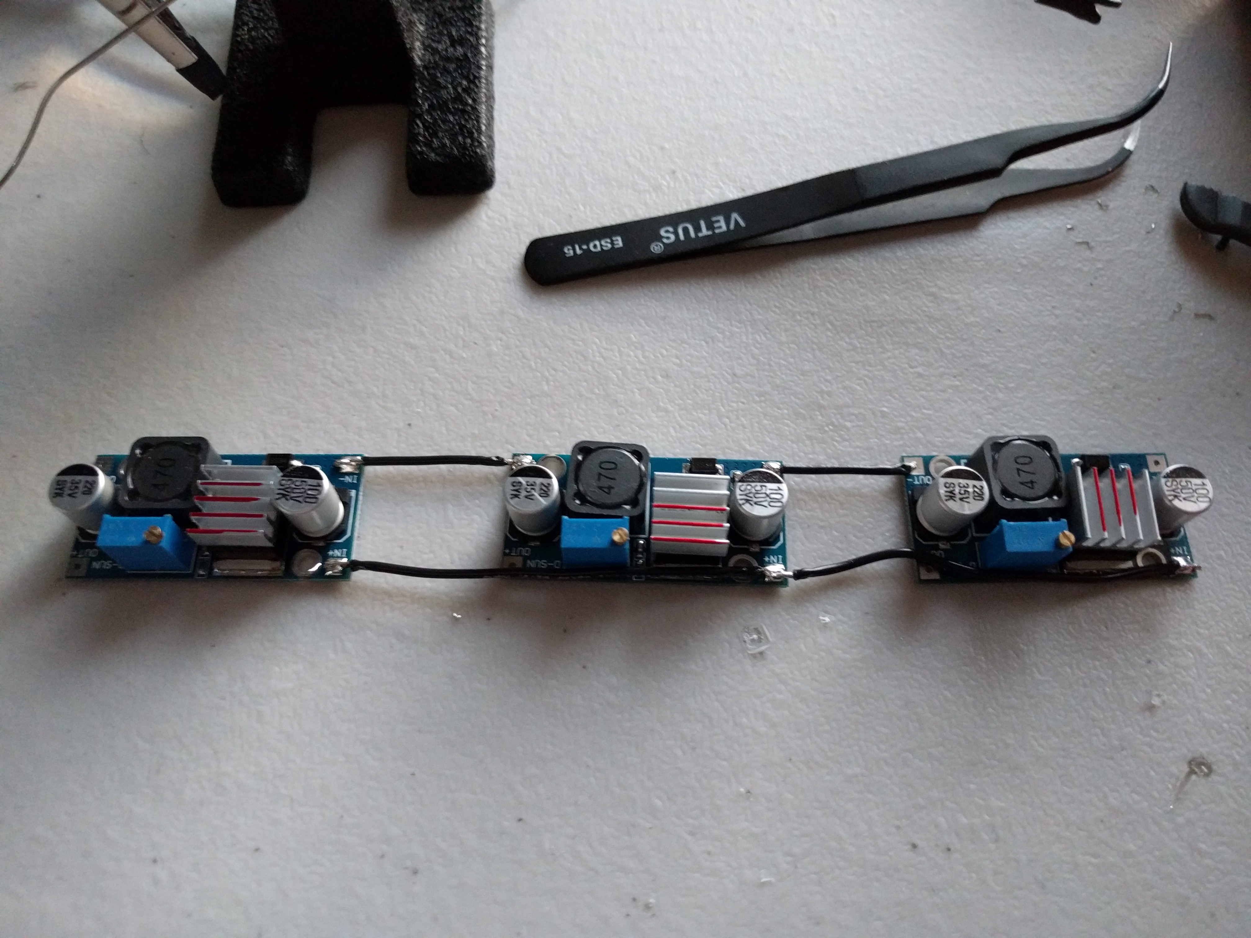
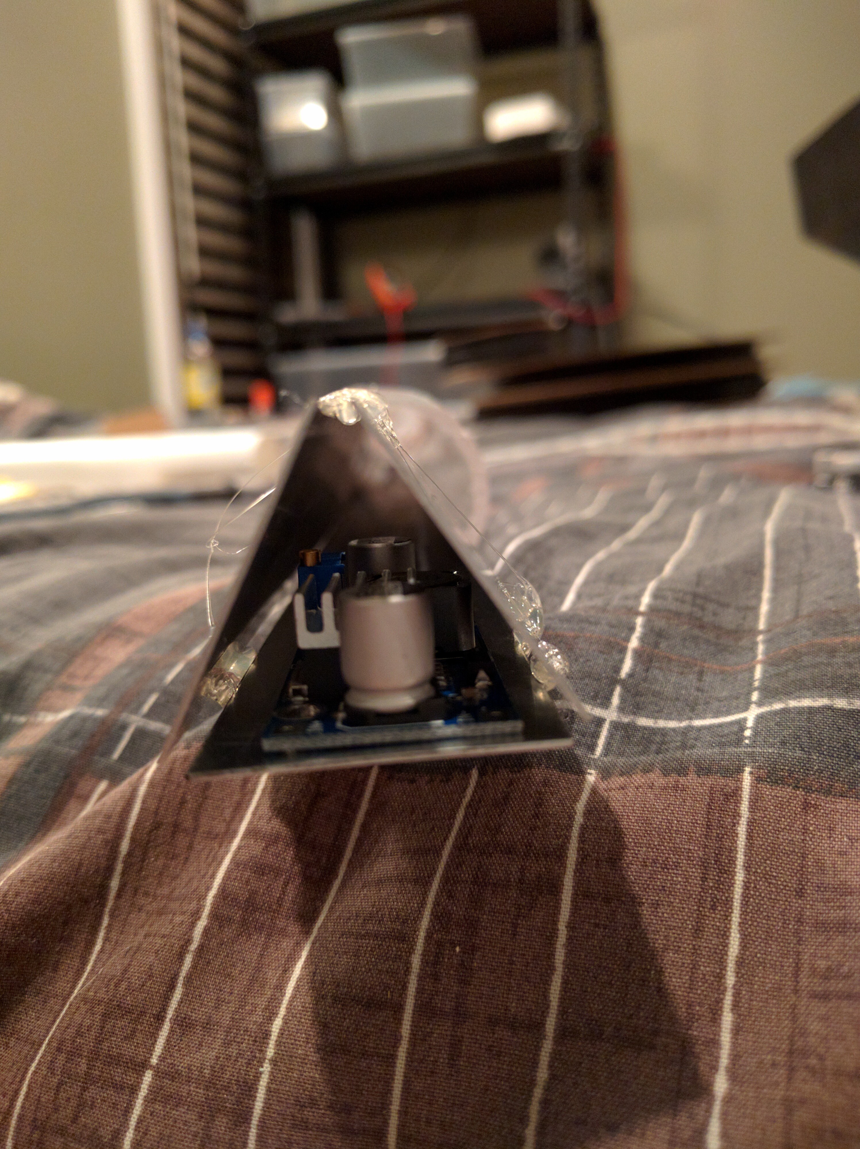
This original design also used a buck regulator for each section that I got off ebay which were then mounted to the 0.025" thick aluminum strips:
![]()
![]()
^ that was just a dry fit, I later mounted the boards with electrically insulating, thermally conductive double sided tape to try and distribute the heat away from the boards.


