Ted Yapo
-
V2.2 Release
07/12/2017 at 04:52 • 33 commentsI am going to maintain and update this log as I add material on building these.
UPDATE 20170716: fixed library and PCB to produce correct solder stencil
UPDATE 20170713: added more info about the battery holder and inductor substitutions, with links to the original parts, and info about the case screws.
UPDATE 20170712: added assembly instructions
UPDATE 20170712: added the 3D printed case design
I should have done this months ago - V2.2 fixed the reversed MOSFET of V2.1, and is basically a complete design, so here it is.
I was going to re-do this in KiCAD, but I got frustrated with it again (third or fourth time), and just paid the $100 for a years worth of Eagle. The hardware and software design is in the GitHub repo.
You can order TritiLED V2.2 boards and V2.x programmer boards from OSH Park. If you have an SOIC-8 programming socket, an SOIC-8 test clip, or don't mind temporarily soldering wires to the ICSP pads on the boards for programming, you don't need the programmer boards - they just let you connect the ICSP lines with pogo pins.
The V2.2 circuit adds a 100-ohm resistor in the battery supply before the reverse-protection MOSFET as discussed in a previous log:
![]()
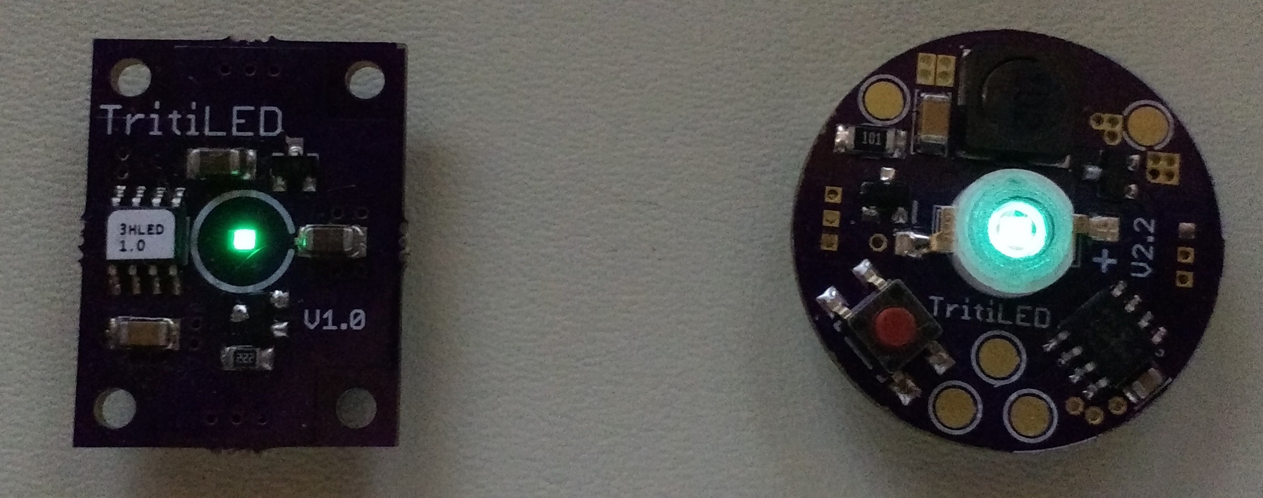
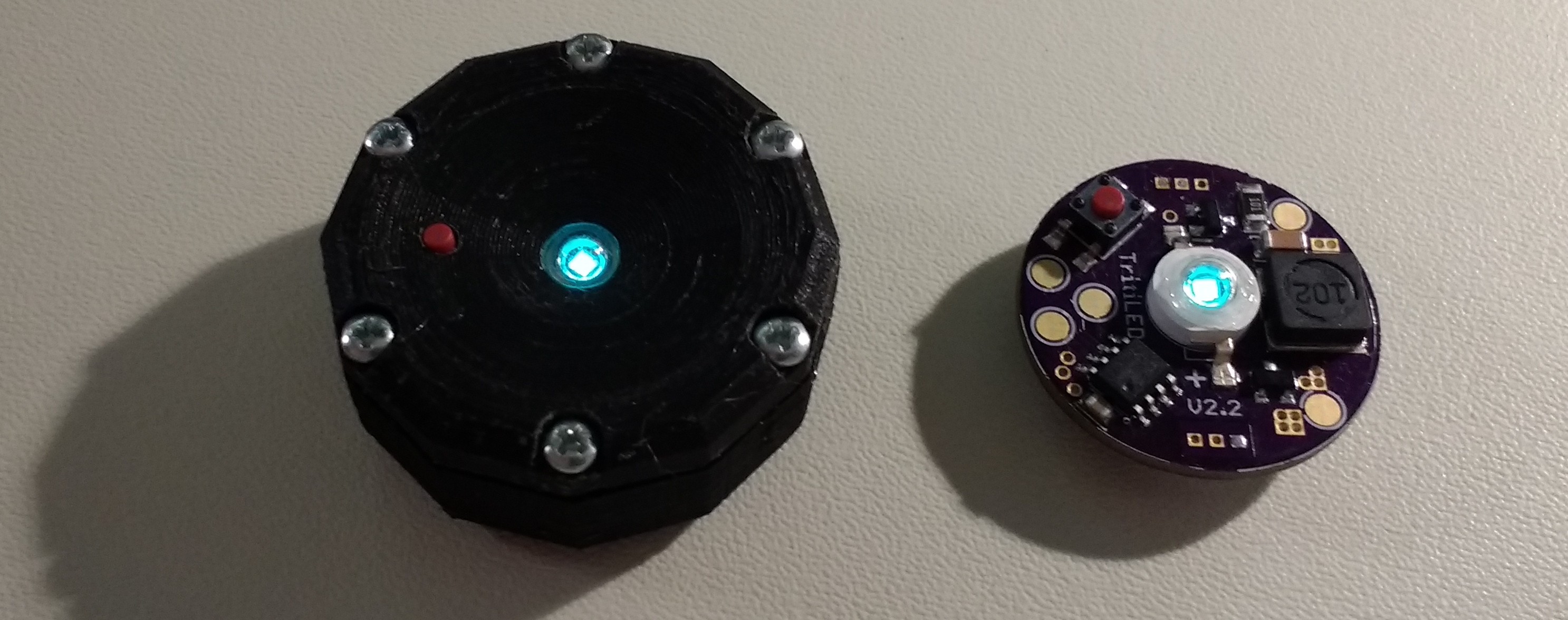
Here's an assembled one with a Chanzon 3W cyan LED (right) next to a V1.0 with a Luxeon Z cyan LED:
![]()
The light output from the V2.2 is much more than that of the V1.0, even though the surface of the LED on the V1.0 looks brighter - this is due to the smaller apparent area of the Luxeon LED. The V1.0 will run for a little over a year, while the V2.2 will run for over 2.5 years with the full software program. This full software includes blinking modes selected with the switch, as well as code which periodically re-initializes the PIC to re-write any RAM values that may become corrupt over time (e.g. from cosmic rays). A separate "barebones" software image can be loaded that dispenses with mode switching and periodic re-initialization, and runs at a slower 32 Hz blink rate to achieve an estimated run-time of over 5 years on a CR2032 cell. This software produces a somewhat dimmer output with noticeable flicker, but it is very usable as a marker. Both software versions are in the GitHub repo, and can be tuned to produce brighter output at the expense of run-time.
Bill of Materials
I need to add a BOM in the GitHub repo, but here are the components listed out
- (1) PIC12LF1571 8-SOIC DigiKey part # PIC12LF1571-I/SN-ND $0.57 each
- (1) Wurth 744062102 1mH inductor. DigiKey part # 732-3676-1-ND $1.57 each
- (1) 10uF 25V 1206 X7R MLCC capacitor. DigiKey part # 1276-1804-1-ND $0.26 each
- (1) 0.1uF 25V 0805 X7R MLCC capacitor. DigiKey part #311-1141-1-ND $0.10 each
- (1) 100 ohm 1206 resistor. DigiKey part # 311-100FRCT-ND $0.10 each
- (1) ZXMN3B01FTA N-channel SOT23 MOSFET. DigiKey part # ZXMN3B01FCT-ND $0.60 each
- (1) DMG2305UX P-channel SOT23 MOSFET. DigiKey part # DMG2305UX-13DICT-ND $0.44 each
- (1) CR2032 Battery retainer. Digikey part # BK-912-G-TR $0.63 each
- (1) Switch E-Switch #TL3305BF260QG. Digikey part # EG5354CT-ND $0.21 each
- (1) CHANZON 3W LED (cyan is best). Find them on Amazon : $9.52/10, AliExpress : $7.90/10, or Ebay (various sellers/prices)
- (1) PCB. Order from OSH Park. $6.15 for 3.
The inductor and battery retainer are substitutions from the original parts I used. The battery retainer is a slight upgrade, being gold instead of nickel. The original nickel part is also available:
(1) Linx BAT-HLD-001-TR CR2032 battery holder. DigKey part # BAT-HLD-001-TRCT-ND $0.73 each.
I have not received any of the gold battery holders yet; from the datasheets they appear to be exactly the same except for finish material.
The inductor is simply more expensive, but with the same size and specs: the old one is not stocked at DigiKey anymore. They are in-stock at Mouser:
(1) Bourns SRR6028-102Y 1mH inductor Mouser part #652-SRR6028-102Y $0.68 each
Again, I haven't tried the Wurth inductor on boards yet, but they appear to be identical parts from the datasheets.
This adds up to $8.35 in materials for single-unit quantities (battery not included: add $0.29 for that). If you build 100 of them, you can get it down to around $6.27 (batteries included :) The older inductor was only $0.68, but DigiKey has 0 in stock with a 22-week lead time - that would save almost $1. The MOSFETs could probably be substituted with cheaper parts, too.
You could save some money by removing the P-channel MOSFET. Reversing the battery might harm the PIC then, but wouldn't cause anything to overheat because of the 100R resistor. You could substitute a shunt diode as a reverse-battery protector, too. After the resistor, it would conduct with a reversed battery to spare the rest of the circuit. You just need a diode with low reverse leakage - even the 1N4148 has a 50uA maximum leakage! The B-E junction of BJTs is supposed to make a better diode for this kind of thing. Still, maybe you shave 10% off the parts costs, not that impressive.
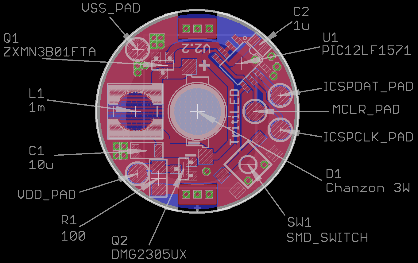
Assembly Instructions
Here's where all the parts go on the board. There are only a few you can screw up: the two MOSFETs, and the 1206 R and C, so watch out for those.
![]()
You could probably hand-solder most of the parts: I haven't tried to hand-solder the inductor; I think you'd need to make the pads larger to be able to do that. I assemble them by applying solder paste with a 22ga blunt needle, then placing the components with tweezers. I reflow the boards on an electric skillet by letting the skillet warm up to around 180C (measured with an IR thermometer), then place the boards on the skillet. As the skillet continues to warm past 220-230, the solder melts, and I take them off.
The battery holder is hand-soldered on the back of the board after reflow.
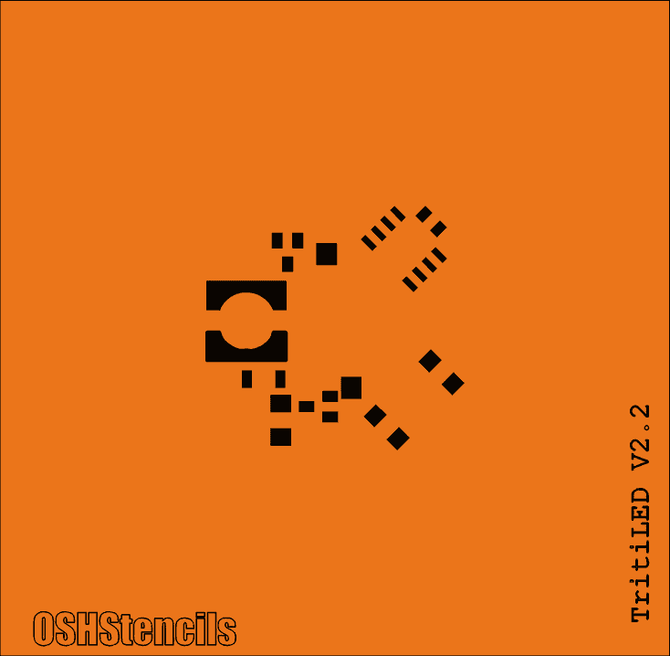
Stencil
(20170716) I fixed the components in the library to produce a correct solder stencil (removed paste from the ISCP pads and added it to the inductor footprint). I have ordered a stencil (for $7.75 with shipping) from OSHStencils, as shown below, but haven't tried it yet - I'll update this log when I have. The gerber file (GTP extension) is in the github repo as well as the updated Eagle files. OSHStencils doesn't seem to have a sharing option like OSH Park, but it's very easy to upload the GTP file and have a stencil made.
![]()
This is my first solder stencil, so we'll see how it goes...
Programming
You can check out this other log for ways to program the PIC. You need a programmer (PICkit3's are available cheap on ebay), and some way to attach to the IC or board.
Experimental Case
I put together an experimental case design in OpenSCAD. A case is important to protect users and the environment from the battery. Without a case, the battery might become loose and be a hazard to children or pets, or the contacts could short on nearby conductors. You must not leave these devices anywhere as markers if the battery is not secured in an inaccessible manner. The case uses screws to keep the battery where it belongs.
Here is what it looks like in OpenSCAD. You can see the details better in the rendering, because I usually print them in black, which doesn't photograph well:
![]()
And here is a printed one next to a bare board
![]()
The switch I used comes in various actuator lengths. If you choose a short one, it will end up recessed in the case. This will keep you from accidentally changing the mode: a toothpick or similar instrument is required. If you choose a longer length, it can protrude from the case and be easily accessible.
The OpenSCAD and resulting STL file for this design are in the GitHub repo.
The case requires (6) screws. I used #2-28 x 5/16" plastic thread-forming screws available on Amazon.
Moving Forward
The V2.2 design works well, and I think 5 years on a CR2032 is probably "good enough." What I'd like to see is smaller and/or cheaper designs. I can imagine forking the design to move in both directions: a cost-is-no-object tiny version, and a cost-reduced, but maybe bulkier one.
Moving back to a chip-on-board LED would help with the size, although the Luxeons I like (Z and C) are $2.74 each in single quantities.
Using a smaller inductor would reduce size and cost and increase efficiency. The problem is that the PIC, in its lower-power 500 kHz oscillator mode, isn't fast enough to produce the short current pulses required of low-value inductors.
New Architecture
What I'd like to try next is using the PIC running at 31kHz, which is the lowest-power clock it can do, still waking from sleep periodically using the WDT. This should dramatically reduce the PIC overhead current drain. To shape the short pulses for the MOSFET drive, I'll try using the 74AUP1G14/differentiator trick from the previous log. That part of the circuit had negligible current drain even with a 3V supply. Moving to an external pulse shaper will allow shorter current pulses than the PIC can do at low clock speeds. Shorter current pulses will, in turn, allow lower valued inductors which are cheaper, more efficient, and physically smaller. In this way, you still retain the flexibility of a programmable part but may be able to reduce the current overhead.
I think I feel a V3.0 coming.
-
CMOS Relaxation Oscillator Fail
07/10/2017 at 03:13 • 23 commentsI have long considered trying to remove the microprocessor from the design, and decided to take a few minutes to test out some ideas. I had the parts for this experiment sitting in a box for over a year...
![]()
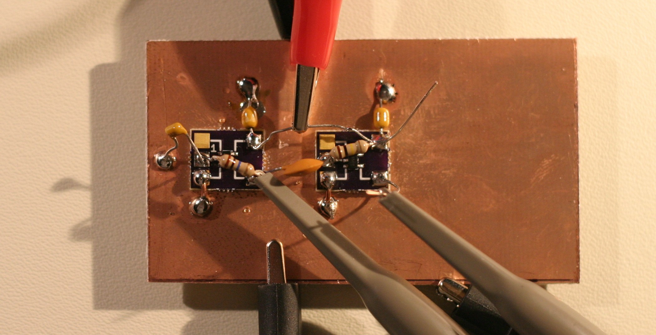
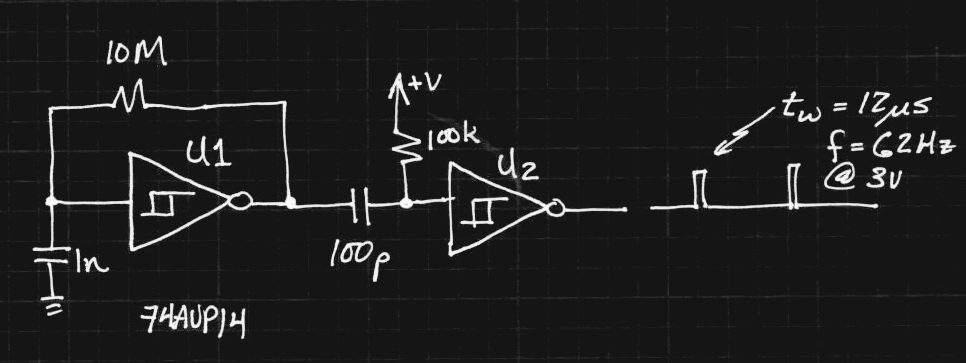
The board has two 74AUP14 Schmitt-trigger inverters in SOT23-5 packages mounted on #Ugly SMD Adapters glued to the ground plane. The first inverter is used as a relaxation oscillator, while the second is used after a differentiator as a short pulse shaper:
![]()
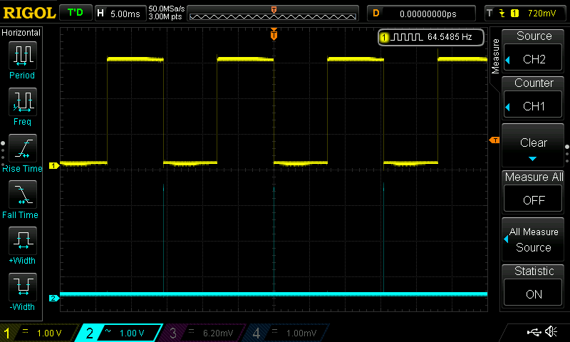
The 1n capacitor has a terrible tempco, so every time I read it, I get slightly different frequencies - especially if I had recently soldered the board, or touched the cap. The output of the first inverter is a nice square wave at around 65Hz (yellow trace):
![]()
Zooming the time scale, we see the output of the second inverter (cyan trace) is a clean 12us pulse on the falling edge of the square wave:
![]()
With a little tweaking, this would be a perfect waveform to drive the MOSFET/inductor boost circuit. Except for one thing: the circuit consumes 160 uA! This is without driving an LED, and is already an order of magnitude more than the "standard" TritiLED program running on a PIC. Craziness!
The problem is that the inverters (74AUP1G14's) consume a lot of power when biased into the linear region, which the relaxation oscillator is always in (the culprit being shoot-through current between the high- and low-side MOSFETs). I was really surprised by this result because the 74AUP is advertised as the "lowest power" family, and the datasheet specifies 0.5uA quiescent drain maximum at 25C. With the feedback connection on the first gate broken, I actually can't detect *any* current used by the circuit with my DMM, which has 100nA resolution.
The pulse shaper seems to consume a negligible amount of current by itself: now I'm wondering how to make a really low-power oscillator.
For the time being, I'll stick with using a PIC15LF1571, but it's still fun to consider simpler options.
Ideas?
UPDATE 20170710
I tested the current drain on the first inverter. I removed the 10M resistor, and briefly charged the 1n capacitor by connecting it to the 3V supply. The capacitor takes about 30 seconds to discharge due to a combination of internal leakage and input current into the inverter. When the capacitor is charged to 3V, or fully discharged at 0V, I read zero quiescent current for the inverter (again, the meter resolution is 100 nA, so I assume the current is less than 50 nA). During the 30 seconds while the capacitor discharges, the current draw increases to a maximum of 220 uA, then falls back down to "zero".
This is why they tell you to ensure than all unused CMOS inputs are tied to either Vss or Vdd. Being in-between can cause some hefty current drains.
SECOND UPDATE 20170710
@AlliedEnvy lent me a clue in the comments - reduce the supply voltage. The circuit oscillates with supply voltages down to 0.25V (at the temperature in my office, anyway), and seems pretty stable above 0.4V. Interestingly, the power consumption drops off dramatically with supply voltage. At 0.95V, it draws 1.0uA, while below 0.75V, the current drops below the 100nA threshold on this DMM. I'll have to drag out the good HP meter to investigate more closely.
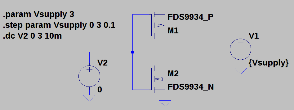
So, the shoot-through current in the middle of the input range is a strong function of supply voltage. To investigate this, I made this quick model in LTspice, using the N- and P- parts of and FDS9934 to make an inverter. I just chose those because it was the first complementary pair I found in the library:
![]()
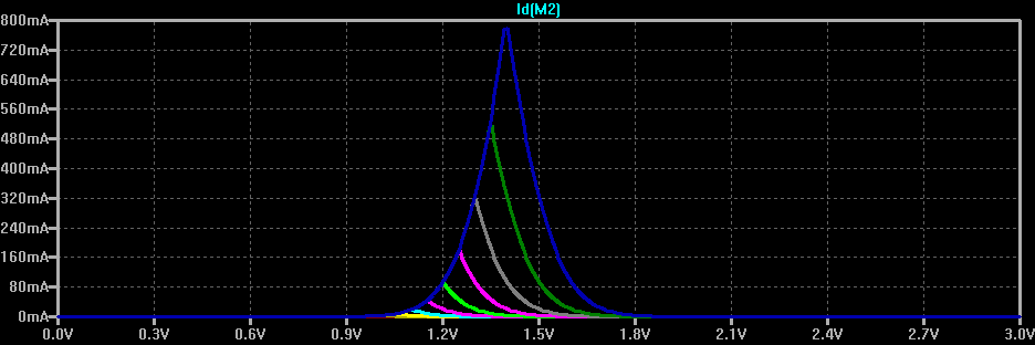
You can see how the shoot-through current gets reduced here. The top (blue) curve shows the current drawn from a 3V supply as the input voltage is swept from 0 to 3V - it peaks near 1.4V at 800 mA for these particular MOSFETS. The other color curves show the same thing for lower supply voltages stepped in 100 mV increments. By 2.3V, the maximum current is below 10mA. By 1.8V, it drops below 10 uA.
![]()
Although there are still issues to be worked out, this may not end up being such a fail after all. Thanks for the helpful comments, everyone! Keep 'em coming - I need all the help I can get :-)
-
Safer TritiLEDs: One simple trick prevents catastrophic failure
06/28/2017 at 15:00 • 0 commentsSo, @Elliot Williams has been playing with similar ideas over on his #ATtiny45 EverLED project. There's some neat ideas over there, including the use of a different microcontroller, inductor sizing, and LEDs. One of the interesting additions he made was a pull-down resistor on the MOSFET gate to avoid the possibility of an un-driven gate being pulled high by whatever voltage fields are around. This can happen when the microcontroller output pin is tri-stated. If the MOSFET is held in a conducting state, the battery is shorted across the inductor and everything gets hot. Elliot mentioned that this happened for him during programming. Of course, the possibility also exists that during the lifetime of the circuit (which may be many years on a single cell), a cosmic ray strike or degraded flash memory could cause a similar problem with the microcontroller code, holding the MOSFET conducting, and possibly causing problems with excess heat or chemical leakage from the cell. It's very unlikely, but also very cheap and easy to protect against.
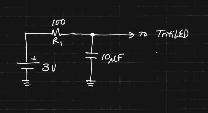
When I re-used this circuit in #Decade Flashlight, I added a resistor in the power supply line to limit current in this case:
![]()
The 10uF capacitor provides storage for the current pulses - in fact, the TritiLEDs run for a few seconds after the battery is removed just from this capacitor.
The 100-ohm resistor limits the maximum current through the inductor and MOSFET. Assuming a 3V battery, the current is limited to 30mA, which will quickly drain a CR2032, but only allow 90 mW of power to be dissipated in the loop - that's low enough not to cause any damage. In practice, the internal resistance of the cell and the parasitic resistance of the inductor make the limit a little lower.
So, it's safer now, but what about efficiency? The TritiLEDs consume from 4-30 uA or more depending on how they're programmed. Let's assume we tune one to about 12 uA, which will run for two years or more on a CR2032. The voltage drop across R1 is then V = IR = (12e-6)(100) = 1.2 mV. Since the current through the resistor and the rest of the circuit is the same, the ratio of power in the resistor to that used by the circuit is 1.2mV / (3 - 1.2mV) = 0.04%. This is ridiculously small, and essentially doesn't change the efficiency or brightness of the circuit at all.
The addition of this resistor is one of the things I'm rolling into the 2.3 board. I've also added them to all of the versions I have made for friends. If you build some of these circuits, please consider adding a resistor in the power supply like this. The value isn't critical - in the above case, the loss is around 1% even with a resistor of 500 ohms.
Sorry about the clickbait title :-)
-
PIC Programming Adventures
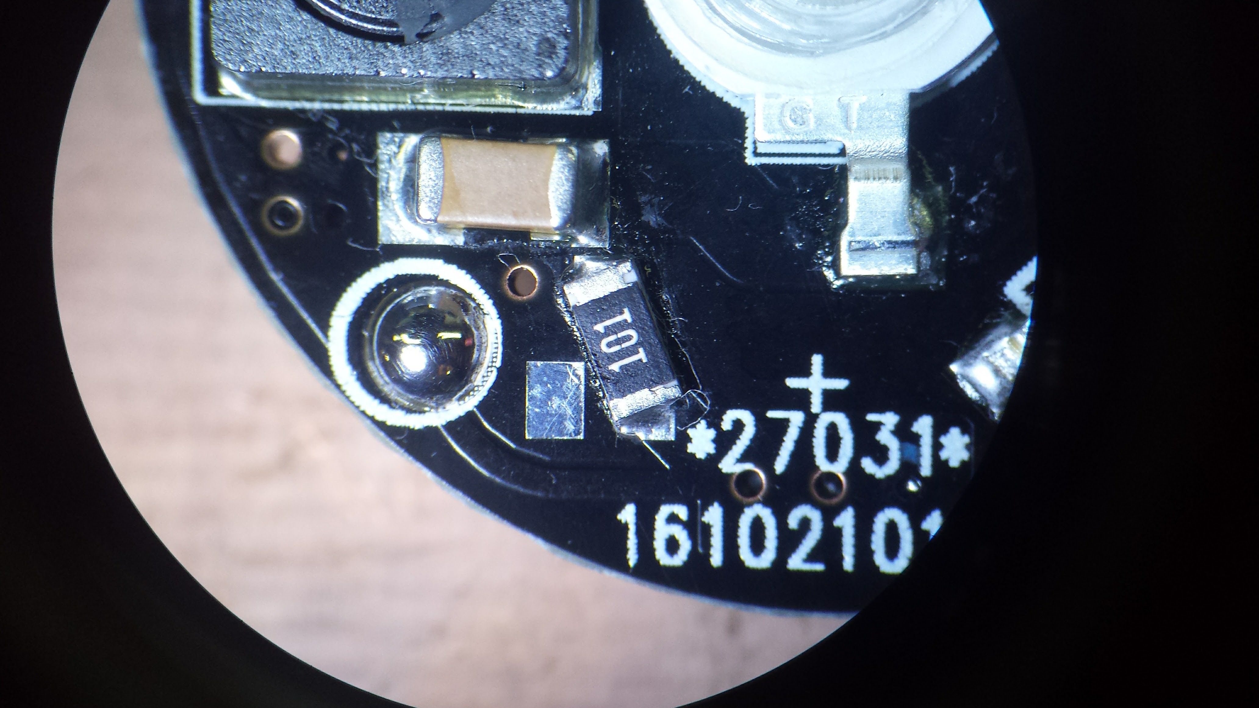
11/20/2016 at 04:40 • 0 commentsI received a batch of V2.1 PCBs this week - this was the board where the reverse-battery-protection MOSFET was backwards. Rather than leave it out, I decided to use a 100-ohm 1206 resistor instead. This limits the current in case of reverse insertion, and protects against rogue PIC code holding the pulse MOSFET on. The resistor is actually a decent fit on two pads of the incorrect SOT-23 MOSFET footprint:
![]()
This resistor is designed in as part of the V2.2 board, in addition to a properly-connected P-channel MOSFET to handle reversed batteries. I usually give boards a quick look under the microscope after reflowing them on the skillet, if only to remove the occasional solder blob, and everything on this one looked fine.
When I went to program this board, though, I kept getting errors - the device ID was always read as 0,and if I persisted, programming failed. At first I thought that there was flux on the programming pads so the pogo pins weren't making good contact. I cleaned the pads with alcohol, then shined them with a pencil eraser, but no luck. I finally soldered wires to the pads to connect directly to a programming header - same problem.
Then I started to wonder about that resistor. Here's how it looks in the circuit:
![]()
The ICSP connections are shown as bubbles. For programming the TritiLEDs, I power the PICs from the programmer - they only consume microamps when they're running, so there's no problem. I think what's happening is that the Vdd to the chip takes a little while to come up, having to charge the 10uF cap through the 100 ohm resistor. This prevents the PIC from going into programming mode when the Vpp line is raised.
After some searching, I found the MPLAB IDE setting for "Apply Vdd before Vpp" with the PICkit3. With that set, the board programs just fine. Elapsed time to debug problem: 3.5 hours. This included some very close observation of this new batch of boards - discussed below. The Vdd programming pad is on the other side of the resistor on the V2.2 board, which is why I didn't see the same problem there.
There's another problem with these boards besides the reversed MOSFETs. The boards have a HASL finish - this can be a problem for battery contacts - with the CR2032 holders I'm using, one of the contacts is a pad on the PCB. Memory Protection Devices, which manufactures many coin cell holders, recommends nickel or gold finish for these contacts in their application note. I think I'll have to pay for ENIG going forward. It's not as good as "hard gold," the thicker coating usually used for edge connectors, but it's probably much better than HASL. Even if the thin ENIG gold were to wear off, there's nickel underneath (some thickness, anyway). Another reason to use OSH Park.
I actually got two batches of boards in the mail this week - one was the V2.2's from OSH Park, which looks like it may be the final PCB design for version 2 - I'd like to assemble a few more of them and run some more tests before I declare victory. The other was the V2.1's from dirtypcbs.com. This was my first experience with this service, and they seem OK - quality maybe a little worse than iTead (not even in the same league as OSH Park), but they're cheap and they warn you over and over that their boards are dirty. You can see the mis-alignment of the soldermask and silkscreen in the image above - look at the programming pad (now blobbed with solder). They do offer your choice of soldermask color for no extra charge. Even though the electrons don't care sometimes you do.
-
These LEDs are too blue...
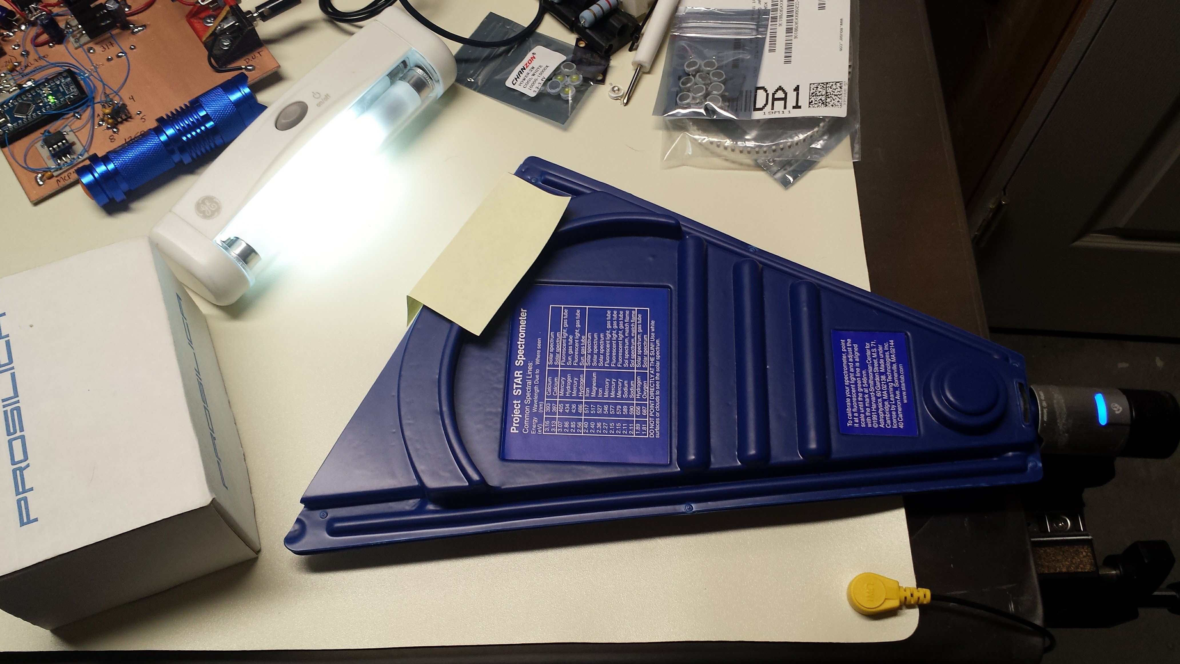
11/09/2016 at 01:23 • 0 commentsSo, in the quest for the Goldilocks LED, I decided to measure the spectrum of the two Chanzon 3W LEDs most likely to be the best for nighttime visual markers: cyan and green. My first impressions of the cyan LED was that it was significantly more blue (shorter wavelength) than other "cyan" LEDs I have seen. To get to the bottom of the issue, I dusted off my Project STAR spectrometer I bought years ago and coupled it to a webcam:
![]()
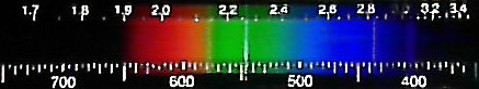
Also shown is the fluorescent tube I used for calibration, producing the following image:
![]()
Calibration for this spectrometer consists of sliding the transparent plastic scale to line up the bright mercury emission line at 546.6nm with the calibration mark. Additionally, you can see that the other strong lines end up where they belong.
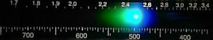
Here's the spectrum for the cyan LED:
![]()
It shows a peak around 495 nm. The "specifications" for this LED state between 490 and 505 nm (no binning; you get the luck of the draw), the latter being almost ideally aligned with the dark-adapted eye sensitivity curve. I was hopeful that these numbers represented the spectrum at high current, accounting for the blue-shift seen in InGaN LEDs, so that at lower currents, they would emit longer wavelengths. Even so, this LED is still the best of the bunch for visibility in the dark.
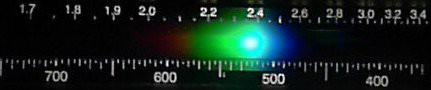
Here's the spectrum from the green LED:
![]()
The peak here is around 520 or 525 nm, which as discussed before represents a good trade-off between day and night vision sensitivities.
-
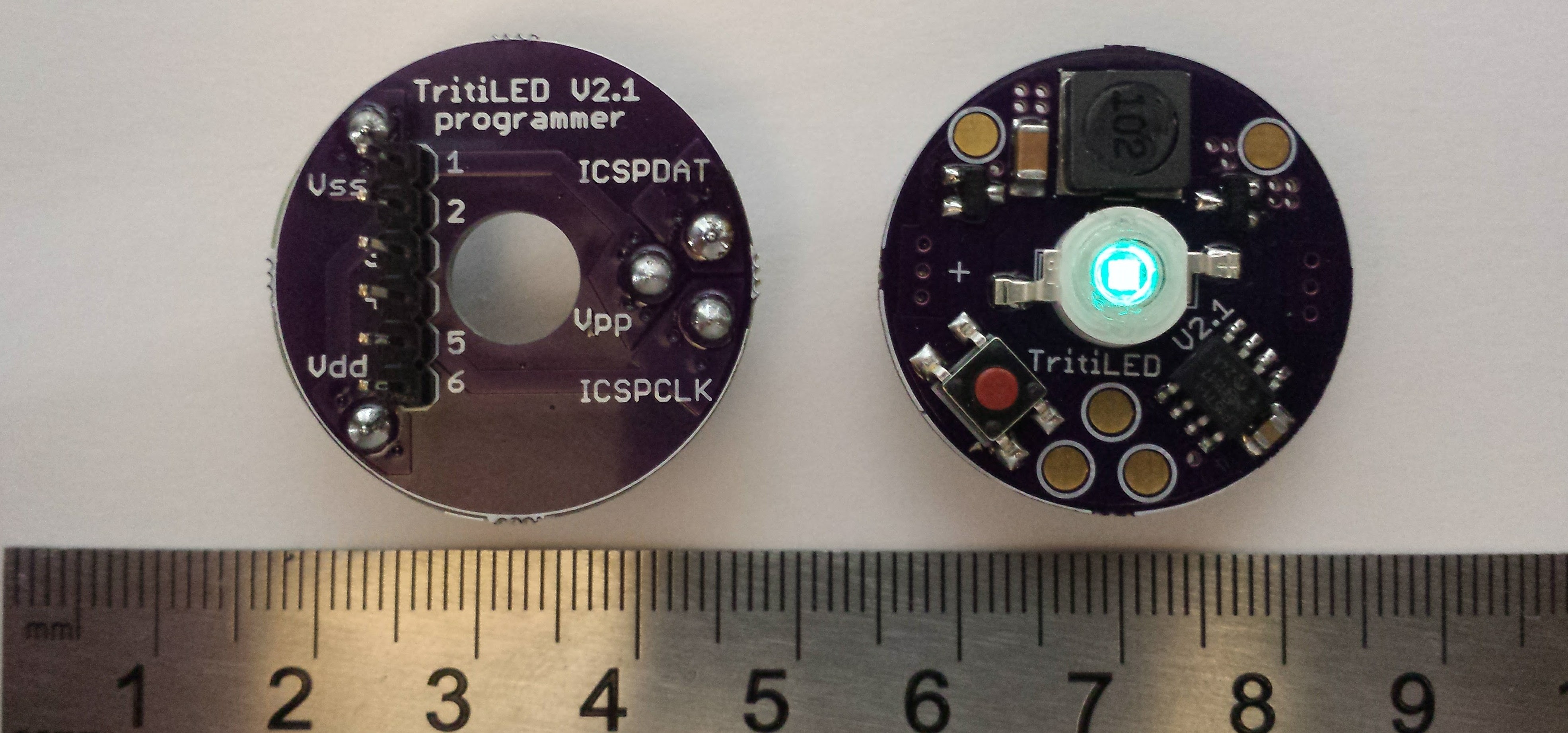
Version 2.1: 5 Years on a CR2032 in 19 Different Colors
10/31/2016 at 21:05 • 18 commentsHere's the latest version using the inductor boost topology, along with the matching programmer board. With a barebones program loaded, this particular unit should glow for almost seven years on a CR2032 (consuming 3.6 uA) - it runs for seven seconds after the battery is removed just from the 10uF of capacitance on the board. Adding code for blinking modes (selected with the button) and some "safety" instructions which periodically re-initialize RAM in case of radiation-induced soft errors brings the runtime down to just over 5 years.
![]()
OK, now the fine print. Three of the 19 "colors" are infrared, so you can't see them with the naked eye. However, they work great as markers with a cheap Gen 1 night vision scope (which I'm certain is bombarding me with X-rays every time I use it). Another "color" is ultraviolet, which should be useful for charging phosphorescent materials, but I haven't tried it yet. Finally, the barebones program has a 32Hz blink rate, which is noticeable in the daytime (surprisingly, the flicker isn't noticeable in the dark, at least to middle-aged eyes). Increasing the blink rate to 64Hz eliminates the flicker, doubles the brightness (to around the level of the V1.0), and increases current draw to 9.1 uA, or about 2.7 years on a CR2032. Further brightness increases come with correspondingly shorter battery life.
Status
I'm currently testing the hardware and software. I know at least a V2.2 will be required, since there's a hardware bug in version 2.1; the reverse-battery-protection p-channel MOSFET source and drain got reversed somehow (I should fire my PCB designer). Interestingly, the device still works, except it offers no protection from reverse battery insertion. Unfortunately, I bought a bunch of boards already, but there's enough room on the board for a quick re-work, or the MOSFET can be omitted entirely.
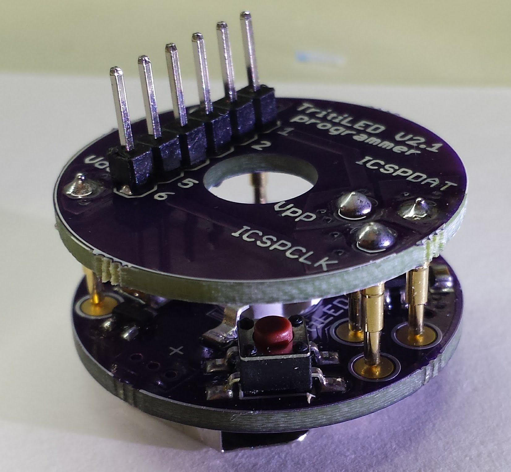
Programmability
I added programming pads on the board to mate with a matching programming adapter board (see below). This is the first time I've used pogo pins, and they're working great. I thought there would be some issue with aligning the boards during programming, but it's very easy to hold them together. Right now, you need a Microchip programmer to plug into the adapter, but I'm considering using @jaromir.sukuba's Arduino-based PIC programmer idea to eliminate the need for a separate programmer. I added a hole in the top so you can see the LED during programming.
![]()
Performance
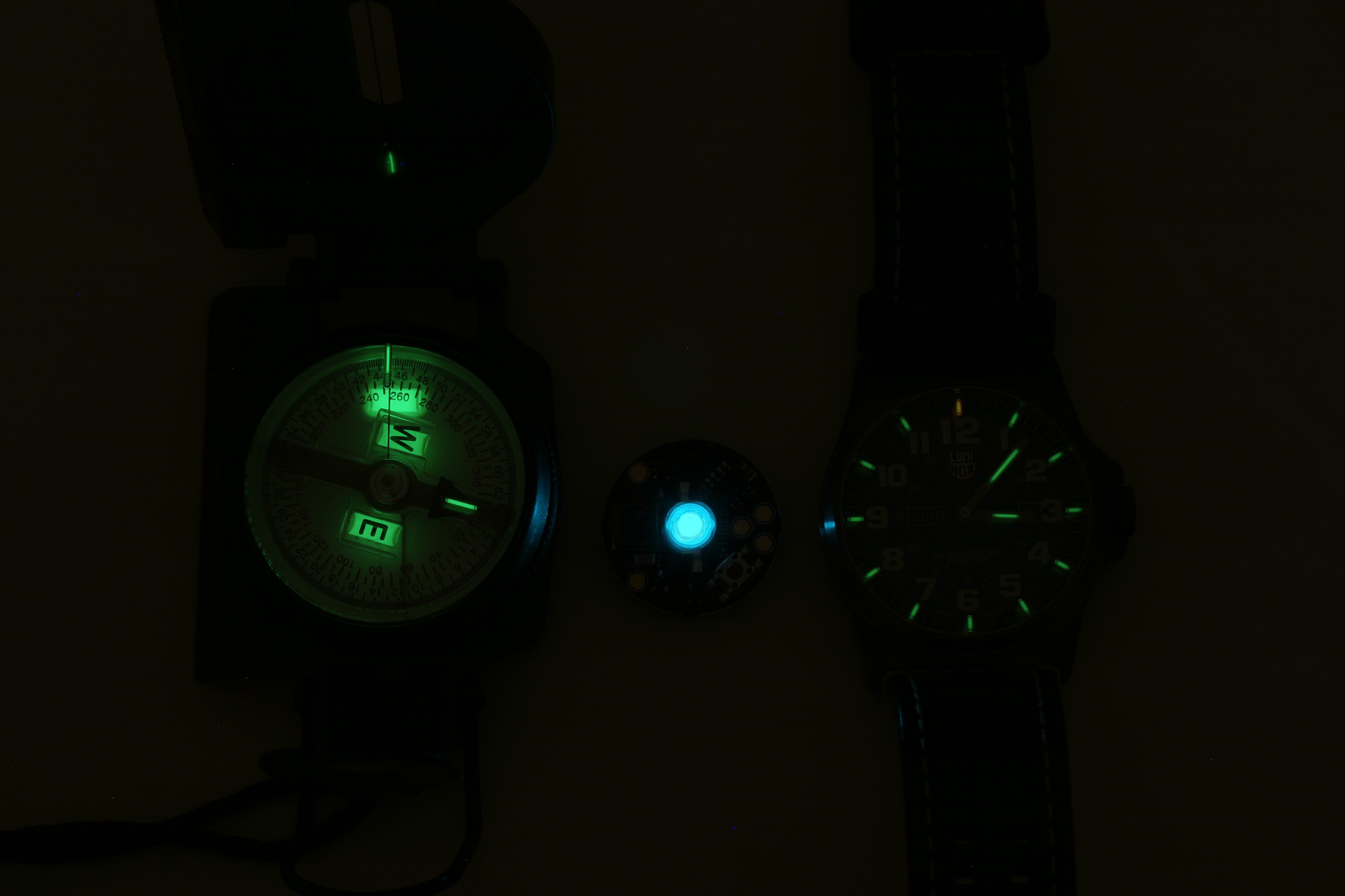
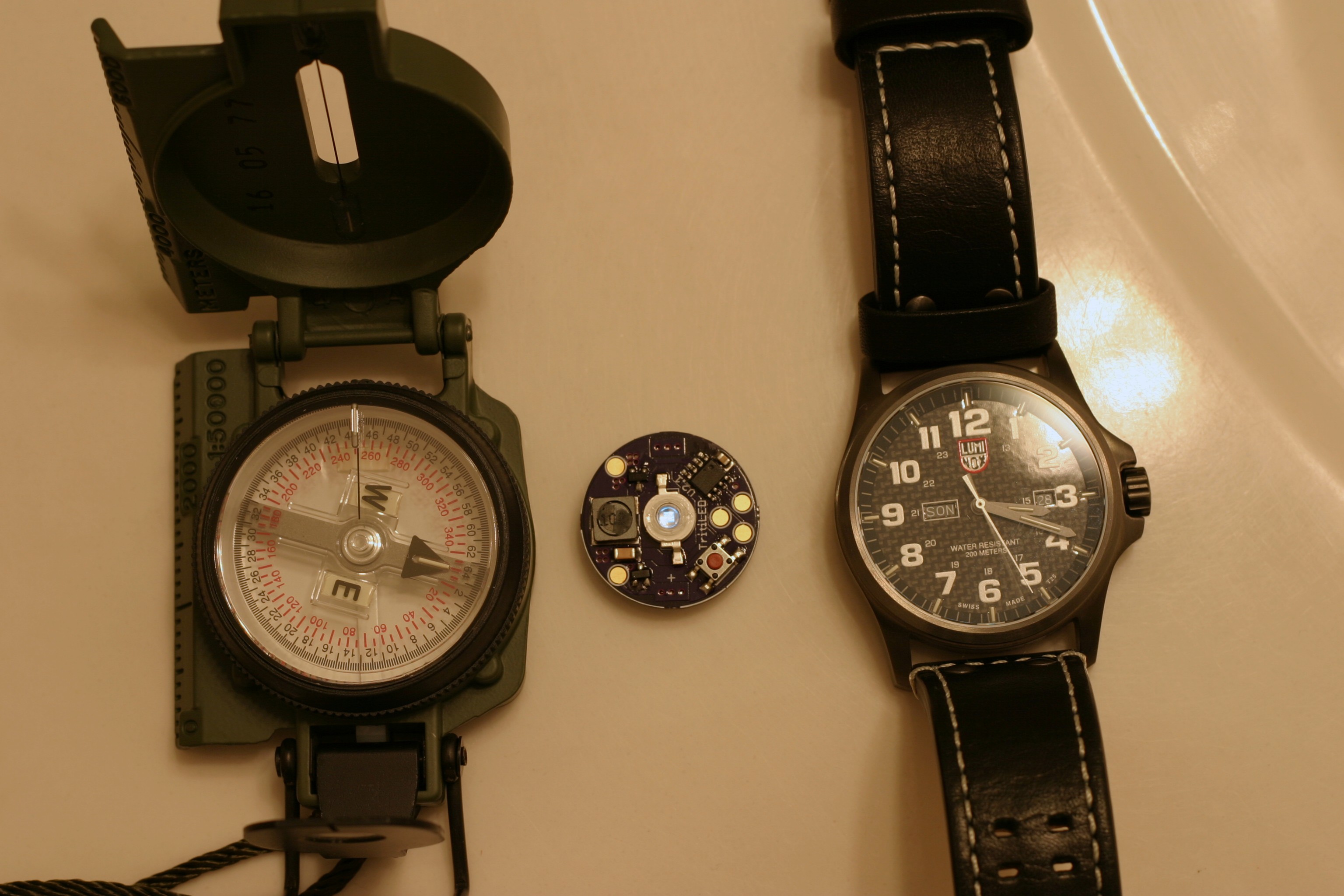
This project was called "TritiLED" because I wanted to make substitutes for GTLS tubes. Since the 5-year version is less bright than the previous versions, it seems best to evaluate it in the original application. After all, you can just keep turning down the brightness to extend the runtime. Here it is compared with a 150 mCi (that's milli-Curie, not micro) tritium compass manufactured in 2016 and a LumiNox watch from 2015. The compass contains the brightest GTLS tubes I have ever seen, and the TritiLED is still many times brighter. It is certainly functional as a nightime marker.
![]()
With the lights on, the glow from the compass and watch has disappeared, but the TritiLED is still visible:
![]()
There's no need to keep the light dim, though. The Maxell CR2032 datasheet lists the "nominal" discharge rate at 200uA (1000-hour rate), which is about 40x as bright as the one shown above. With larger cells/batteries, this circuit can produce a maximum of about 2000x as much light, which would be around 10mA drain (about 350 hours from 2x lithium AA's).
Circuit Design
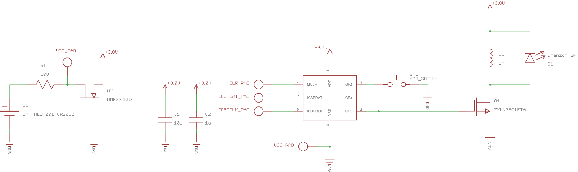
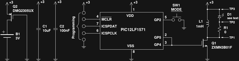
Here's the design for version 2.2:
![]()
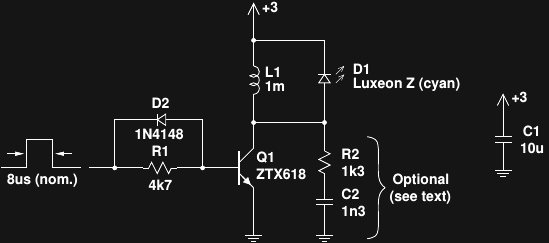
Q2 protects the circuit (and battery) in case the power is connected incorrectly - it only allows current to flow with the proper polarity. Unlike a simple blocking diode, the MOSFET introduces almost no voltage drop in this circuit, maintaining high efficiency. The PIC12LF1571 sleeps most of the time, periodically awakened by the internal watchdog timer to pulse the LED. GP4 and GP5 are paralleled to provide more current drive to switch Q1 faster. Turn-on speed is not really an issue, because at turn-on, there is no current flowing through Q1. At turn off, however, with the maximum current through Q1, rapid switching is important to minimize the time that there is simultaneously voltage across and current through Q1 - any such power is wasted. When Q1 is on, current builds through L1, while D1 is reverse-biased. When Q1 switches off, the current through L1 continues to flow, now through D1 to produce a pulse of light. R1 is included in the testbed board (see below) for measuring the current through D1 and calculating electrical efficiency.
I chose these particular MOSFETs because they were the first ones I found meeting my specs (and in SOT-23 cases). It's certainly possible that cheaper equivalent ones can be found.
The pushbutton switch SW1 allows selection of different modes. A "weak" internal pullup holds the line high when the button is not pressed, and de-bouncing is done in software. Unfortunately, the weak pullup isn't very weak, and pressing the switch draws about 80uA of current - many times that of the circuit itself. Currently, the software allows selection of a constant glow, fast pulse (8 Hz) or slow pulse (1Hz). The average current drain is the same for all modes, so that the pulse modes are much brighter and attention-grabbing than the constant glow.
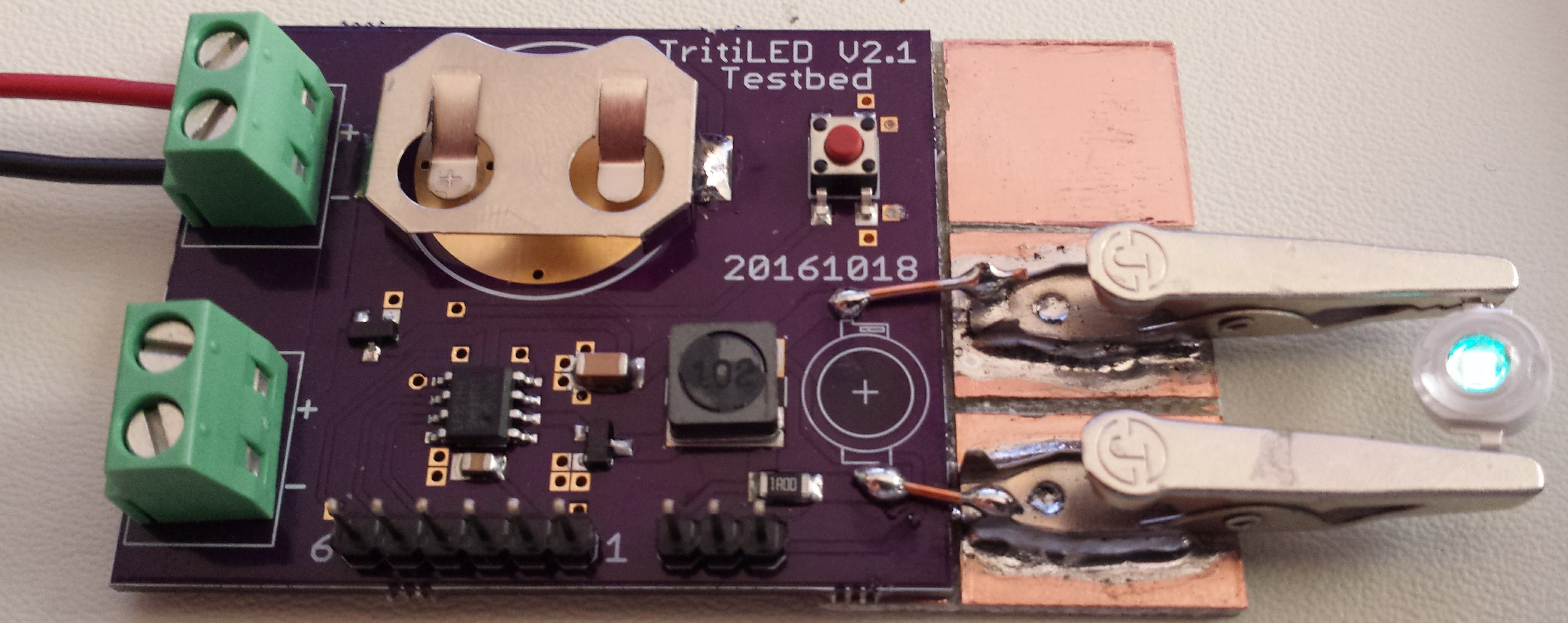
Pads on the production board (or headers on the testbed) allow for serial programming of the PIC12LF1571. Here's an image of the testbed, which is the same circuit as the circular board, with the addition of a 1-ohm resistor at R1 and more convenient headers for measurement. On this version, I've added clips for testing different LEDs.
![]()
Component Tolerances
One of the problems with this circuit is that the Bourns SRR6028 inductor is specified with a +/- 30% tolerance. Otherwise, this series of inductors would be ideal - nice form factor, current handling, shielding, SRF, etc. Since most of the power in this circuit goes into the LED, that 30% inductor tolerance translates into a large power tolerance, and hence a large runtime tolerance. The PIC12LF1571 has an OSCCAL register which can speed or slow the clock by +/-12% which you can use to partially compensate for the inductor tolerance, but that still leaves a lot of possible variation between units. I have no idea about battery capacity tolerance (I've never seen one specified), and it may be that over a period of years, with varying temperature and aging components the 30% inductor isn't the worst variability factor. But, I'm still trying to come up with a software compensation scheme - I've tried dropping N out of every 256 pulses, for instance, as a power fine-tuning, but this introduces a noticeable blink or flicker.
LED Selection
I've chosen to use LEDs from Chanzon for several reasons:
- Availability: I've purchased these LEDs on Ebay, Aliexpress and Amazon
- Hand-solderability: the case is a little larger than I would like, but you don't need to reflow the board
- Color selection: see the 19 types below
- Chip size: available with 1W (30x30 mil) or 3W (45x45 mil) chips, or 5w (4x 30x30 mil chips) in the same package
- Accessibility: they readily agreed to make some small-volume custom LEDs for me for another project; most manufacturers won't give me the time of day
- Price: the green 3W LEDs are $0.43 each (qty 10) and cyan are $0.79 each (qty 10)
About the only downside is the lack of detailed datasheets. But since I'm figuring out how to measure the LEDs anyway, it doesn't really matter.
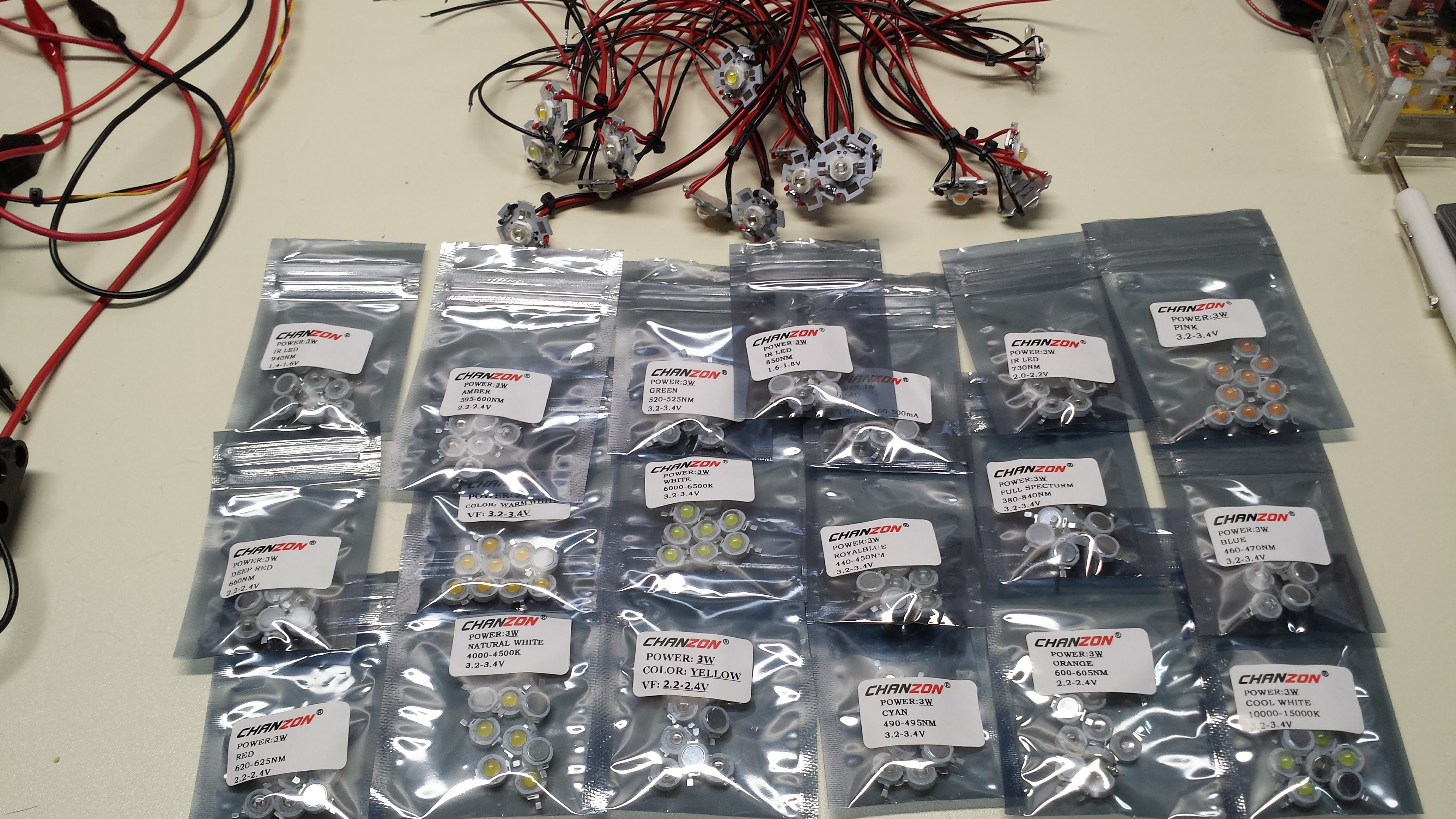
Here are the LEDs, with some mounted on boards for testing:
![]()
The colors are (in random order):
- 940nm IR
- Amber
- Green
- 850nm IR
- UV
- 730nm IR
- Pink
- Deep Red
- Warm White
- White
- Royal Blue
- Full Spectrum (grow light)
- Blue
- Red
- Natural White
- Yellow
- Cyan
- Orange
- Cool White
I've tested most of these 3W LEDs with the #Automated LED/Laser Diode Analysis and Modeling system, and am currently finishing the code to evaluate the efficiency of the various LEDs in this circuit. I know for the green and cyan LEDs, the V2.1 circuit achieves about 98-99% of the achievable LED efficiency, but for some of the other colors, circuit adjustments will be required to get really good efficiency, since the efficiency peak for some of these LEDs is in the 100mA range, as opposed to around 10mA for green and cyan. A combination of different inductor values and different software timing will probably be required. For some LEDs, moving to a "1W" (30x30 mil) chip from the "3W" (45x45 mil) chip may be enough. Luckily all of the colors are available in both sizes.
Next Up
I need to spin a version 2.2 to fix the backwards MOSFET. While I'm at it, I might think about making the board smaller. It's a shame that the CR2032 holder is 30mm across for a 20mm cell; the 30mm diameter PCB certainly seems over-sized. Once I have a fixed, tested design, I'll add design files and code for download.
I'm continuing to measure the different LED characteristics and determine the circuit and software changes to drive the various LEDs efficiently. Of course, some of the colors will be less efficient as markers, but it seems a shame not to support the wide variety of colors available.
Finally, I'm measuring the electrical efficiency of the circuit with the testbed board to see how much more could be gained.
-
Intermission
09/03/2016 at 23:09 • 0 commentsI'm taking some time off from this project, and mostly wanted a placeholder so I can remember where I left off - I have a bad habit of "taping over" memories from suspended projects. So, this is just a jumble of thoughts I'll update as they come until I start this thing back up.
The Energizer Cylindrical Lithium Primary Battery Applications Manual has some great info about this unique battery chemistry, and discusses the two-stage discharge seen in the graphs, temperature performance, etc. The only thing I don't like about these batteries is the need to use spring contacts, which are notoriously unreliable. I would like to spot-weld tabs on them. A homebrew spot-welder may be in my future. I guess I should ask Energizer if they produce tabbed versions first.
The previous lumens/watt calculations I did for the Luxeon Z LEDs use the datasheet-reported output at 500mA, so they're a valid comparison assuming the three LEDs share a similar efficiency curve, which is doubtful. I need to actually run the tests to compare these LEDs properly.
I should compare the battery model to back-of-envelope calculations. I should also add a model for ultra-capacitors, which would be trivial. Of course, just running with a capacitor (if you have one) would be a quick test, since the energy density is low.
The V1.0 design isn't protected against reverse battery insertion, which is easy to do with coin cells. This paper from Ti discusses adding a MOSFET to protect the circuit with minimal loss. Assuming I end up using a MOSFET for the LED driver, I might be able to find a dual version cheaper than two individual parts. http://www.ti.com/lit/an/slva139/slva139.pdf
I didn't think to compare the efficiencies of different LED colors - it turns out that green LEDs have traditionally been less efficient than other colors, although this information is probably dated. It would be interesting to survey the field and see where the most efficiency (electrical-to-eye-sensitivity) ones are. The luminosity curve probably dominates here, so even inefficient LEDs near the eye sensitivity peak win.
It might be interesting to consider smaller batteries. The CR2032 has decent capacity and is widely available, but is a little bulky compared to the other components (at least until I start using larger LEDs).
I need a way to make some simple absolute intensity measurements. All the data I have been able to collect so far for LED intensity has been relative. If I can measure the absolute output at even one current setting for an LED, I can calibrate the relative intensity measurements. This would allow comparison of the intensity of different LEDs. I think I'm going to build an integrating sphere with a 12" hollow styrofoam sphere and barium sulfate paint. It should be easy enough to get a reading for the total output at high current, which will be enough to calibrate the whole relative curve.
Jim Williams wrote a few applications notes detailing his designs for very efficient fluorescent LCD backlight drivers. The technology is different, but the idea of measuring and optimizing electrical-to-optical efficiency is the same. There are probably some good clues in there.
-
Estimating Battery Lifetime
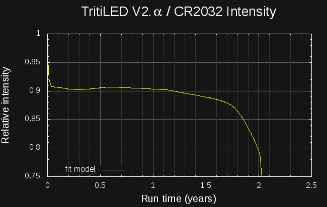
09/02/2016 at 22:16 • 0 commentsI've created a model for common lithium primary cells to predict the run-time for very-low-drain devices. Here's the estimated intensity of the V2.0α circuit run from a CR2032 cell. The light lasts for over two years, with the brightness only dropping about 10% in the last six months.
![]()
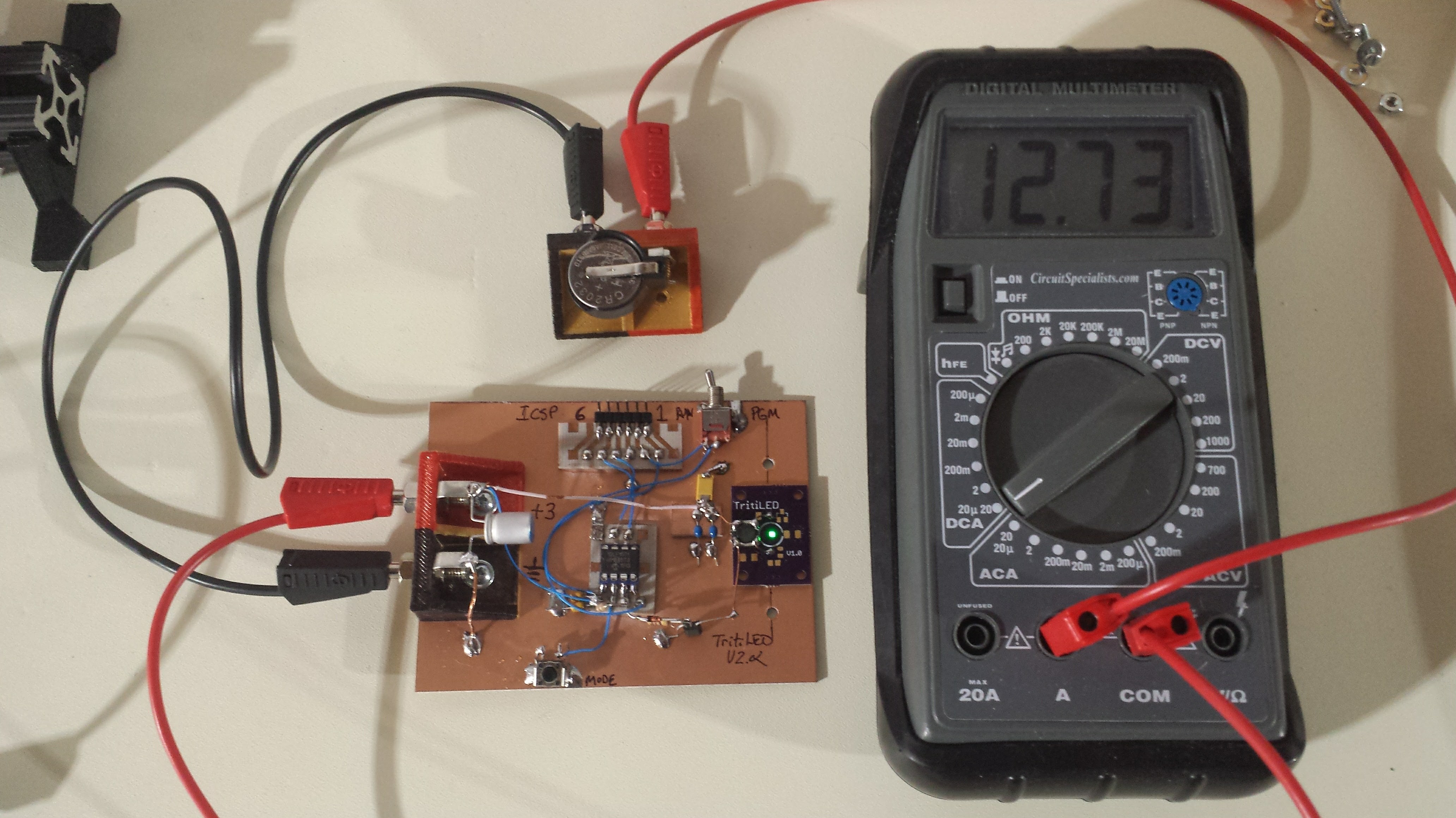
To estimate the performance, the first thing I did was make a better prototype, shown here consuming less than 13uA from a not-quite-fresh CR2032:
![]()
This prototype uses an SMD 1mH inductor, which was glued to the top of a V1.0 PCB. In this case, the PCB just acts as a mount for the Luxeon Z LED, which has to be reflow soldered - no other components of the V1.0 circuit were populated. The circuit is the same as shown in the previous log, using a PIC12LF1571 and a ZTX618 transistor as switch. No RC snubber network is used. This breadboarded version uses almost 1uA less than the solderless-breadboard one. I haven't directly compared the brightness yet, but it seems similar. The difference may be due to the new SMD inductor vs the previous through-hole one.
LiMnO2 Battery Model
I've been using a simple model for LiMnO2 batteries (the "CRx" series like CR2032's or CR123A's) for some time. The model seems to work pretty well under the following assumptions:
- current drain is averaged, by capacitance if required, to near-DC: no strong current pulses
- average drain is less than 0.0005C. This is around 100uA or less for a CR2032 or 800uA for a CR123A.
- temperature is assumed to be constant around 20C
- battery shelf-life is not exceeded. The model considers the battery dead after the shelf-life has elapsed, regardless of the predicted remaining capacity. Shelf-life for LiMnO2 batteries is commonly considered to be 10 years, while that of LiFeS2 cells (lithium AA and AAA) is 20 years.
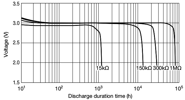
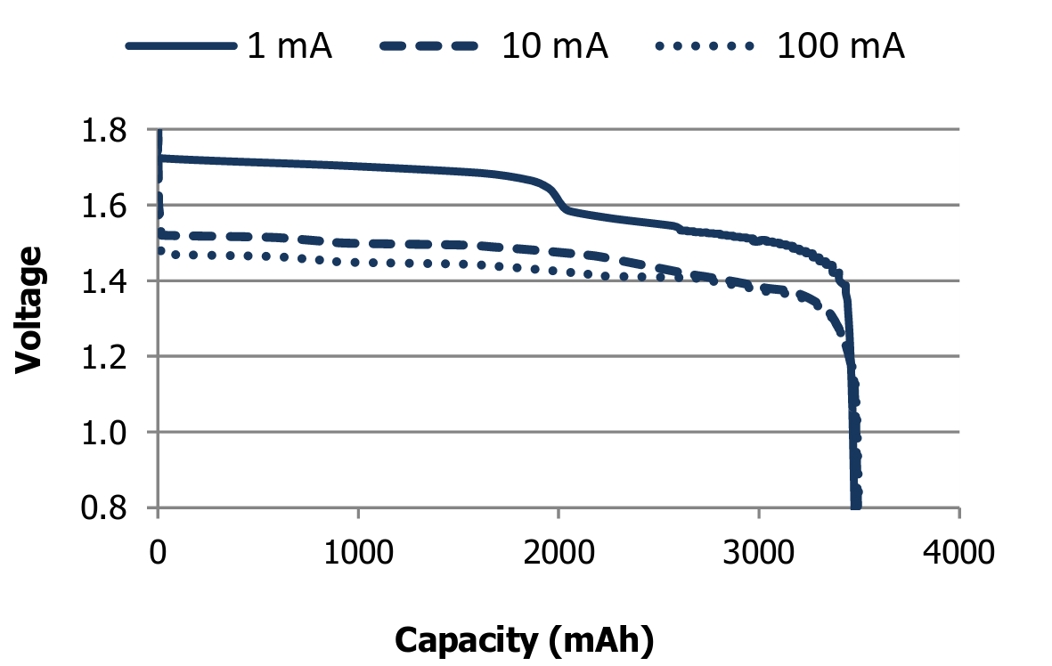
I based the model on the following curve from the Maxell CR2032 datasheet, which shows the cell voltage vs used capacity for a 1M resistor (solid line; ignore the lower pulsed discharge curve):
![]()
I digitized this curve and wrote some python code to model the battery from this data. The battery object is initialized with the nominal cell capacity (in mAh), so that different sized cells can be modeled. Three functions complete the battery model:
- battery.dead(): reports true once either the remaining capacity drops to zero or the shelf life is exceeded
- battery.voltage(): returns the cell voltage based on the remaining capacity using interpolated digitized data from the above curve
- battery.use_amp_seconds(amps, seconds): decreases the remaining capacity of the cell by amps * seconds
The model is intended to be used in an integration loop, as shown in the following code for simulating constant-resistance discharge. At each time-step (chosen to be one hour here), the battery voltage is estimated based on the remaining cell capacity. The current draw of the device (in this case a resistor) is evaluated given the source voltage, and this current is used to decrease the remaining cell capacity. The loop continues until the battery reports dead.
#!/usr/bin/env python
import sys
import Li_battery
# constant resistance discharge
R = float(sys.argv[1])
# integration time step in seconds
timestep = 3600.
battery = Li_battery.LiMnO2(220.)
t = 0
while not battery.dead():
  voltage = battery.voltage()
  print t/3600., voltage
  current = voltage / R
  battery.use_amp_seconds(current, timestep)
  t += timestep
Using this program, I was able to re-create the following plot from the datasheet for constant-resistance discharges:
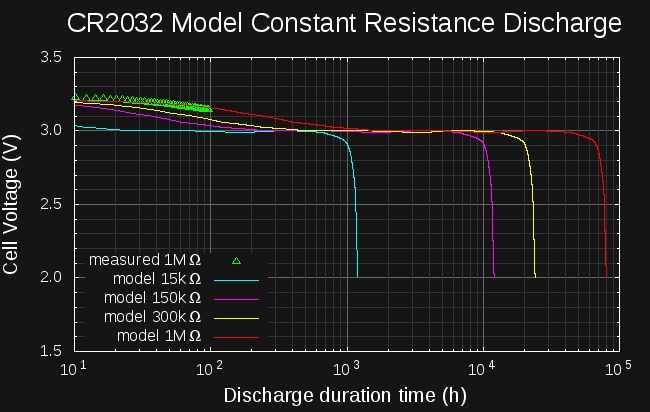
![]()
![]()
The curves match very well, and the model is able to re-produce the expected run-times and voltages with two exceptions. First, the predicted voltage for the 15k curve is too high - but, this resistance results in a nominal drain of 200uA, or 0.0009C, which exceeds the valid range of the model (violates assumption 2 above). For high-drain devices, which deplete the battery relatively quickly, you might be better off just testing the real device than trying to model it. Devices at the model cutoff of 0.0005C would run for around 90 days (the 15k resistor would only run for about 50 days).
For the higher resistances, the predicted voltages are very close, except for the initial segment. In the datasheet curves, the cell voltage falls from the initial peak to the nominal 3.0V within the first 20-30 hours. The model predicts a much slower drop, up to 1000 hours for the 1M resistance. To reconcile the two, I have been testing a battery with a 1M resistor this week. I've connected a fresh CR2032 to a 1.1M resistor in parallel with 10M input-resistance RS232 current meter, and have been logging the voltage during discharge. Shown as green triangles in the right-hand plot, the measured discharge curve is very close to the model, and doesn't drop quickly as the datasheet shows. I have no idea how the datasheet curve was produced, but the model actually seems closer to a real battery.
Circuit Power Model
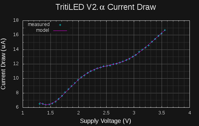
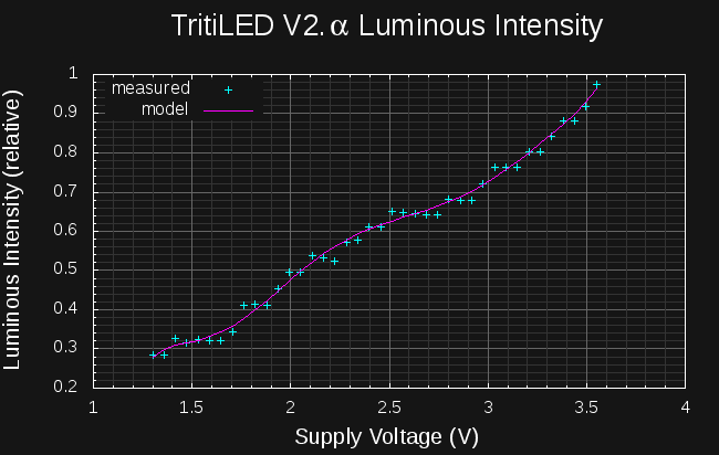
The battery model is only half of the simulation: to predict device run-time, the current vs voltage characteristics of the device must be known. For the resistor simulations above, Herr Ohm has conveniently given us V = IR, but for other devices, we need to come up with our own model. As luck would have it, the analyzer I am building to measure LEDs and laser diodes can also measure the I/V curves of other devices, including whole circuits. In this case, I've used it to measure the I/V curve and brightness of the new TritiLED circuit:
![]()
![]()
On the left, the current consumed by the circuit is shown as a function of supply voltage, while the right-side plot shows the relative brightness of the LED vs. supply voltage. I used these curves to make a device model that can predict the runtime and brightness of the circuit: simple polynomials have been fit to filter and interpolate the raw data points. The simulation code is similar to that for fixed resistors, except the device current and brightness are evaluated based on the measured curves:
#!/usr/bin/env python
import Li_battery
import tritiled_v2a
device = tritiled_v2a.tritiLED_model()
battery = Li_battery.LiMnO2(220)
# integration time step in seconds
timestep = 3600 * 24
t = 0
while not battery.dead():
  voltage = battery.voltage()
  current = device.current(voltage)
  intensity = device.intensity(voltage)
  print t/3600, intensity, voltage
  battery.use_amp_seconds(current, timestep)
  t += timestep
The results of this simulation were plotted to produce the brightness vs time graph shown at the top of this log.
LiFeS2 Battery Model
I've also made a model for lithium AA and AAA cells. These cells are unique in that they have a 20-year shelf life; low-drain devices should be able to run this long. The Energizer LR91 (AA) datasheet shows the following curves:
![]()
I digitized this plot and created a similar model for these cells. Again, I consider the model valid for drains up to 0.0005C, which equates to 625uA for AAA or 1.75mA for AA cells. Using this model, I predicted the following brightness for a TritiLED run from a pair of AAA cells. The light should last for over 9 years, with the brightness falling roughly 10% in the first five years, and an additional 10% in the last four.
![]()
At the limit of 0.0005C, devices would last about 83 days: the model is useful for predicting run-times longer than this. The limiting factor in the accuracy of this model for higher drains seems to be the battery internal resistance. If a good model for this resistance can be developed, it may be possible to extend the useful range of the battery model to higher-drain devices.
Code
The code for the battery models can be downloaded here on hackaday.io. It's released under the MIT license.
-
Version 2.α
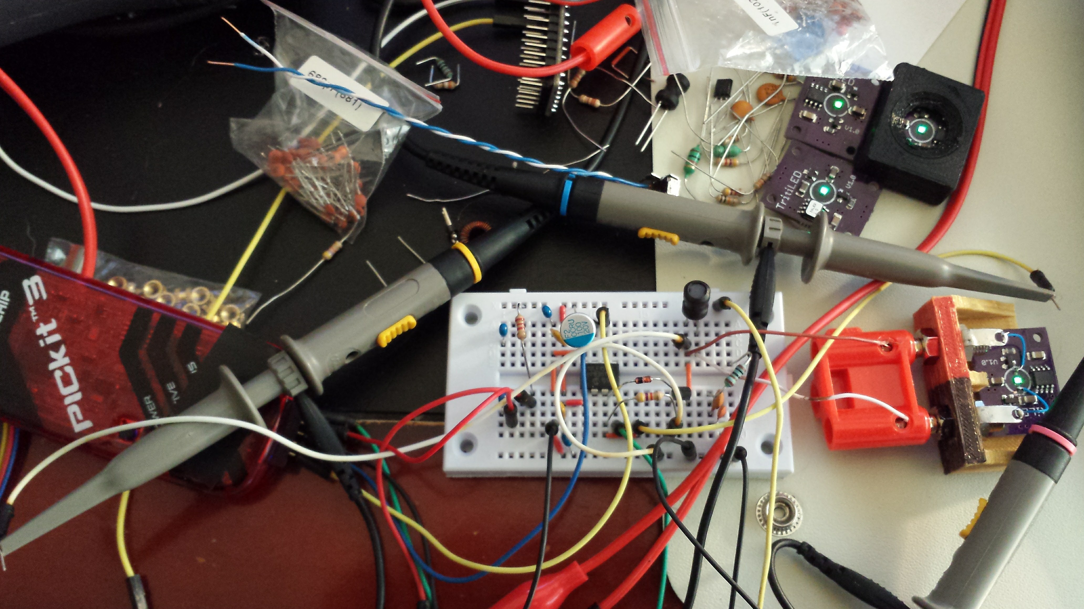
08/30/2016 at 18:33 • 0 commentsI breadboarded a first cut at a more efficient circuit this past weekend. Consensus is that it appears a little brighter than the 1.0 circuit (not measured with the camera yet), and a back-of-the-envelope estimate says it will run for two years on a CR2032 battery (a better analysis is coming in the next log). It consumes 49% less current than V1.0, and can be made to blink bright flashes instead of a constant glow while maintaining the same current draw. The circuit incorporates some good ideas suggested by Jaromir and Tony. Here's the mess of a prototype:
![]()
Pulse Circuit
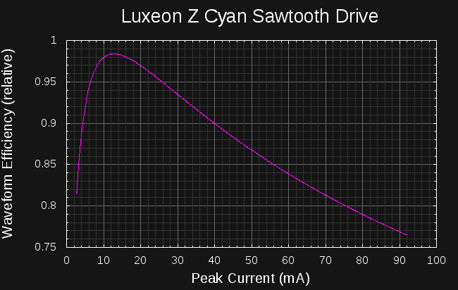
The design started with an analysis of the efficiency of sawtooth current drive waveforms for the Luxeon LED, as I did for a 5MM LED earlier:
![]()
With sawtooth waveforms like those produced by the inductor-LED circuit I had simulated before, the best LED efficiency is seen at around 13 mA peak current. After a little experimentation with PIC clock speeds and inductor sizes, I came up with this circuit that generates peaks of around 15 mA (roughly estimated from peak LED forward voltage and the measured I/V curve):
![]()
The design is based on discussions I've had with Tony about single-shot boost converters, and it works pretty well, as long as the LED doesn't have a reverse-protection diode inside (this one does not). A 1 mH inductor is huge for a switching power supply, but all of the four different through-hole styles I had in this value worked in the circuit to some degree. One was superior, though - I will need to find an SMD version with similar properties. As discussed earlier, pulses from the PIC turn on the transistor to magnetize the inductor, then the inductor "discharges" through the LED to create the light pulse. For these tests, I used a modern PIC as suggested by Jaromir. So far I've only used a PIC12LF1571 I had on-hand; I am also going to try a PIC12LF1552 which is supposed to have a slightly lower sleep current.
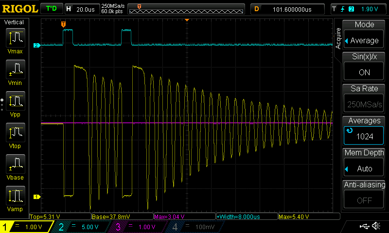
The ZTX618 is an awesome transistor (at a premium price), with super-high beta and super-low Vce(sat) - evidence of this can be seen in the waveforms below, where the collector of Q1 drops to 38 mV during the pulse. The high beta allows a high value for R1, limiting the wasted base current. D2 is critical to achieving high efficiency with this circuit - without it, Q1 turns off slowly, wasting power at the critical peak inductor current. Here are the waveforms observed at the input, driven by a single PIC output pin (channel 2, cyan), and at Q1's collector (channel 1, yellow). The supply voltage of 3.04 V (channel 3, magenta) is shown at the same offset as channel 1.
![]()
Two things are immediately apparent. First, you can see the trick to lighting LEDs with these small current pulses - use multiple pulses every time the PIC wakes from sleep. Here, the PIC is waking every 16 ms to output two pulses. Waking every 8 ms to output a single pulse is less efficient because of the overhead involved in starting the PIC clock each time. Waking less often to generate more pulses is even more efficient, but the blinking becomes noticeable. Push this far enough, though, and you get a very brightly flashing beacon at the same power. Pulsing the LED 128 times every 1 second produces a nice attention-grabbing display using around the same average current.
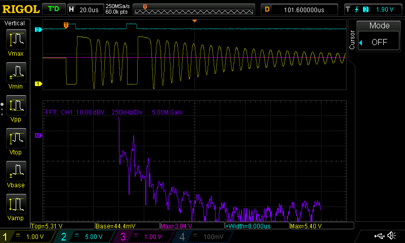
The second thing evident is that the circuit rings like a bell after each pulse. The delay between the pulses is actually chosen to coincide with the ringing, so that the next pulse starts on the down-swing of the oscillation. Fine tuning this delay seems to add a few percentage points of efficiency. You can see the spikes in the spectrum at 145 kHz and the second harmonic at 290 kHz here:
![]()
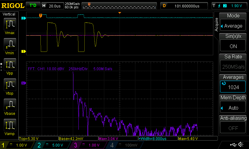
A PCB made for this circuit probably wouldn't make an efficient radiator for these LF frequencies, but since one of my hobbies is hunting LF navigation beacons, I wanted to clean this up. I had previously dealt with this kind of ringing in another circuit following the advice in the Ti Applicaton Report SLPA010 "Reducing Ringing Techniques for NexFET High-Performance MOSFETS," so I gave the same approach a shot here. Some cut-and-try analysis provided the values for R2 and C2, which form an RC snubber network across the output. With those parts in place, the ringing is greatly reduced:
![]()
Unfortunately, this also reduces the efficiency of the circuit by 10%. When I design a board for this version, I'll include sites for these parts and decide afterward if they should be populated based on some (probably crude) emissions testing.
Performance
I haven't used the camera method to compare the brightness of this circuit with the V1.0, but I think it's brighter - two other people have agreed. One of the complications is that this version produces a longer-wavelength output because the LED is driven with lower current. This may also complicate the camera comparison method, but at least I'll have some objective data on the comparative brightness.
As for current draw, here's a summary of the two versions:
Version Current drain @ 3V Estimated CR2032 lifetime (years) V 1.0 26.3 uA 0.95 V 2.α (no snubber) 13.5 uA 1.86 V 2.α (snubber) 15.0 uA 1.67 Here, the estimated lifetime was computed by dividing the nominal 220 mAh capacity rating of a CR2032 by the measured current draw at 3.0V. This under-estimates the actual run time because as the battery voltage drops, the circuit draws less current. I actually have a much better approach that models the battery capacity as the voltage drops over the lifetime of the cell to give more accurate predictions; I'll present it in the next log. Initial results of the new method show a run-time over two years for the new circuit.
Next Steps
As luck would have it, I found a DigiKey box on my doorstep this afternoon containing a few different types of 1 mH SMD inductors, low-Vgs MOSFETS, and PIC12LF1552's. I used a BJT in the first prototype because that's all I had for through-hole devices. The next step is to build an ugly-style prototype of the same concept to see how it works - for all I know the crazy parasitics in the solderless-breadboard version may be important circuit components :-)
I have a lot of PIC pins left over. This was convenient for the prototype, since I could just leave the programmer connected (except the Vdd line) during testing. It would be nice to have the pic programmable on the PCB, so I am considering adding card-edge contacts on one side of the board for the ICSP lines.
I'd also like to add a button to select maybe three different modes - continuous glow, fast flash, and slow flash, each of which maintains the 2-year battery life. Mostly, just I need to add some switch-debouncing code to make it work
Luminosity Standards
I would like to find a cheap, repeatable luminosity standard. Wikipedia provides some clues about a possible DIY version based on older standards:
One candlepower was the light produced by a pure spermaceti candle weighing one sixth of a pound and burning at a rate of 120 grains per hour.
My whaling schooner is in dry dock for repairs at the moment, so that one is probably out. Luckily, a newer standard was devised:
The candela is the luminous intensity, in the perpendicular direction, of a surface of 1 / 600 000 square metre of a black body at the temperature of freezing platinum under a pressure of 101 325 newtons per square metre.
Freezing platinum - I wonder if my refrigerator gets that cold if I turn it all the way down ;-)
When this project got blogged on hackaday.com, one of the commenters, [Paul] mentioned another possibility:
Though a great tool, unfortunately this device is useless for one of the best uses of a tritium light in astronomy: camera calibration. A tritium light source (e.g. from http://www.betalight.nl/ ), is an ultra-stable, zero-noise low-intensity narrowband light source ideal for testing and calibrating CCD camera sensors: https://www.google.com/search?q=betalight+ccd+testing
Now, if I could buy a betalight in the US (I'm looking at you, NRC), I would never have started this project!
There must be a way to do DIY luminosity calibration. Ideas, anyone?
PIC Source Code
For those interested, here's the source code I used for the tests. There are actually a number of different ways of generating 8us pulses - I found that one instruction cycle at a 500 kHz fosc was much more efficient than 8 cycles at a 4 clock MHz (CMOS!). You can change the watchdog timeout (e.g 1s), and the number of pulse pairs (e.g. 128) to produce bright strobes at the same average current draw. It's released here under an MIT license (I need to start a GitHub repository for this project!).
;;; ;;; single_shot_boost.asm : PIC12F1571 code for CR2032-powered LED glow marker ;;; ;;; 20160828 TCY LIST P=12LF1571 #include <p12lf1571.inc> ERRORLEVEL -302 __CONFIG _CONFIG1, _FOSC_INTOSC & _WDTE_ON & _PWRTE_OFF & _MCLRE_OFF & _CP_OFF & _BOREN_OFF & _CLKOUTEN_OFF __CONFIG _CONFIG2, _WRT_OFF & _PLLEN_OFF & _STVREN_OFF & _BORV_HI & _LPBOREN_OFF & _LVP_ON CBLOCK 0x70 counter ENDC ORG 0 RESET_VEC: BANKSEL LATA clrf LATA BANKSEL OSCCON ; movlw b'01101011' ; 4 MHz osc movlw b'00111011' ; 500 kHz osc movwf OSCCON BANKSEL TRISA movlw b'101111' ; RA4 as output movwf TRISA BANKSEL WDTCON ; movlw b'000010101' ; WDT 1s timeout ; movlw b'000010011' ; WDT 512ms timeout ; movlw b'000010001' ; WDT 256ms timeout ; movlw b'000001111' ; WDT 128ms timeout ; movlw b'000001101' ; WDT 64ms timeout ; movlw b'000001011' ; WDT 32ms timeout movlw b'00001001' ; WDT 16ms timeout ; movlw b'000000111' ; WDT 8ms timeout ; movlw b'000000101' ; WDT 4ms timeout ; movlw b'000000011' ; WDT 2ms timeout ; movlw b'000000001' ; WDT 1ms timeout movwf WDTCON N_PULSE_PAIRS equ 1 MAIN_LOOP: BANKSEL OSCSTAT btfss OSCSTAT, MFIOFR ; check for osc ready goto MAIN_LOOP ; spin here until osc ready banksel LATA movlw N_PULSE_PAIRS movwf counter PULSE_LOOP: bsf LATA, 4 ; start inductor ramp-up bcf LATA, 4 ; end inductor ramp-up nop nop nop nop bsf LATA, 4 ; start inductor ramp-up bcf LATA, 4 ; end inductor ramp-up nop decfsz counter goto PULSE_LOOP sleep goto MAIN_LOOP END -
Calculating Scotopic Luminous Flux
08/27/2016 at 13:17 • 0 commentsI'm working on a new circuit (really!), but did these calculations last night, and thought the results were interesting.
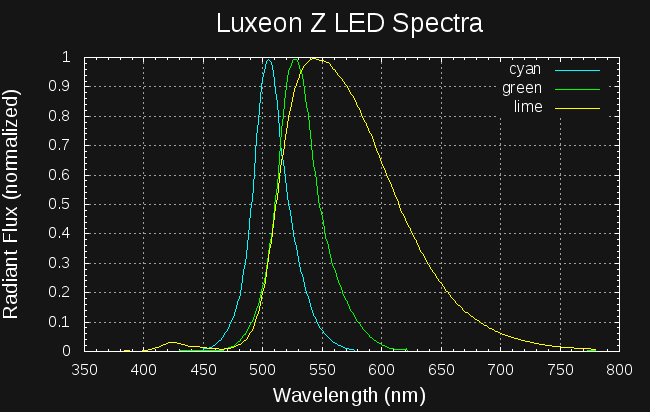
LED datasheets often quote the luminous flux in lumens, based on the daytime visual sensitivity curve (photopic vision). This is calculated by integrating the LEDs spectral radiant flux with the photopic luminosity function, and reflects how bright the LED appears to daytime-adapted eyes. For nighttime marker use, we are interested in "scotopic lumens" which would more accurately measure how bright the LEDs look to dark-adapted eyes. I scraped the LED spectral curves from the datasheet and with some numeric manipulation in an octave script, calculated the scotopic luminous flux for the three Luxeon Z LEDs I have been looking at:
Color Photopic Lumens (datasheet) Scotopic Lumens (calculated) lm/W (photopic) lm/W (scotopic) Electrical Power (W) Cyan (LXZ1-PE01) 68 782
46 528
1.48 Green (LXZ1-PM01) 108 618
71 407
1.52 Lime (LXZ1-PX01) 199 642
142 459
1.4 The datasheet lists the output at 500 mA, so I multiplied by the forward voltage (from datasheet curves) for each of the LEDs to get the input power.
The lm/W (electrical watts) columns in the table are the most interesting. For true dark-adapted vision (like in a cave or really good astronomy site), the cyan LED wins at 528 lm/W - but, this LED is poor for daytime vision. During the day, the lime LED is far superior to either of the others at 142 lm/W - and it takes a close second place behind the cyan at night. If you're making a glow marker and want it to be generally useful in all lighting conditions, the lime LED seems like the best choice. The only downside: it costs $4.20 vs $2.76 for the others. The marketing department over at Lumileds has their act together.
Details
Here's how I calculated the values in the table. Math and/or photometry nerds may want to check my approach; others may feel the desire to skip this entirely :-)
The datasheet provides the photopic luminous flux (in lumens) and a normalized spectrum for each LED. I digitized the spectra with Engauge Digitizer, shown replotted on the same graph here:
![]()
The datasheet lists the photopic luminous flux,
, for each LED in lm. This is calculated by weighting the spectral flux,
, by the dimensionless photopic luminosity function,
:
To calculate an analogous scotopic luminous flux,
,we can perform the same integration, this time weighting by the scotopic luminosity function,
:
This would be straightforward, except that the spectral flux isn't given directly in the datasheet. However, we can calculate the spectral flux from the given luminous flux and the dimensionless (normalized) LED output spectrum, which I'll call
. The spectral flux is proportional to the normalized spectrum:
Substituting this, we can solve for the constant C:
and then evaluate the scotopic luminous flux:
The raw data files and the octave script I used to perform these calculations can be downloaded here.
Update: writing this log revealed a scaling error in the original octave code; I've re-run the numbers and updated the code and table.
TritiLED
Multi-year always-on LED replacements for gaseous tritium light sources