will.stevens
-
A punched card stepping mechanism
09/24/2016 at 20:05 • 0 commentsThe video below shows a gravity powered motor connected up to cogs that advance a punched card one step at a time. An alternative (perhaps more straightforward) way of advancing the card would be to attach thread to one end of it, and pull it directly with the motor. I believe that using the mechanism with cogs is preferable, because the cogs hold the card in place, and correctly aligned, in the reading mechanism.
-
Relay contact separation, relay dropout voltage
09/19/2016 at 22:38 • 0 commentsI found a way of making a consistent gap between the contacts of a relay. Rather than have printed slots to hold relay contacts in place, instead I first position them close to the pole, held apart from it by a 0.4mm thickness of card, then glue them in place using quick set epoxy. In the photo below you can see the cardboard arches that fit over the pole nail while the glue is drying to keep the contacts at a fixed separation. The small blocks that the contacts sit on are located under the centre of gravity of the 20mm contact nails, so that the nails don't fall off before the glue dries.
![]()
Both of these relays have a pull-in voltage of about 5 volts (one was 4.6 V, one was 5.3 V) and a drop-out voltage of about 1.5 volts (1.6 V and 1.3 V). Because the contacts are so close to the pole (compared with my previous similar relays) the force that pulls the contacts closed is greater, so I can use thicker flexible struts, which makes the relays less fragile.
It occurred to me recently that the zinc coating on these galvanised nails might be playing a role in keeping the dropout voltage higher than it would be otherwise. In armature relays, there is a thin non-magnetic separator between the armature and the core to prevent the relay staying on - if the armature and core are in direct contact then only a very small voltage is needed to keep the relay on, and it may remain on when it should be off. (In this note it is called a residual stud). I don't have one of these, but perhaps the thin layer of zinc helps? If so then the relay should become more prone to sticking on over time, if the zinc coating wears off with repeated closing and opening. It should be possible to test this hypothesis by looking for a galvanized and a non-galvanized nail of the same shape in the hardware shop.
-
A reed relay toggle flip that directs the toggle signal to one of two outputs
09/16/2016 at 23:14 • 0 commentsIn order to make a modulo 12 counter like this one, but using easy to make single throw relays, a circuit like the one shown in the video below is needed.
In the video the circuit uses 4 DPST relays, I believe that it could be made with 6 SPST relays instead. If so then this means that a modulo 12 counter will require 30 SPST relays.
-
A better bidirectional movement mechanism
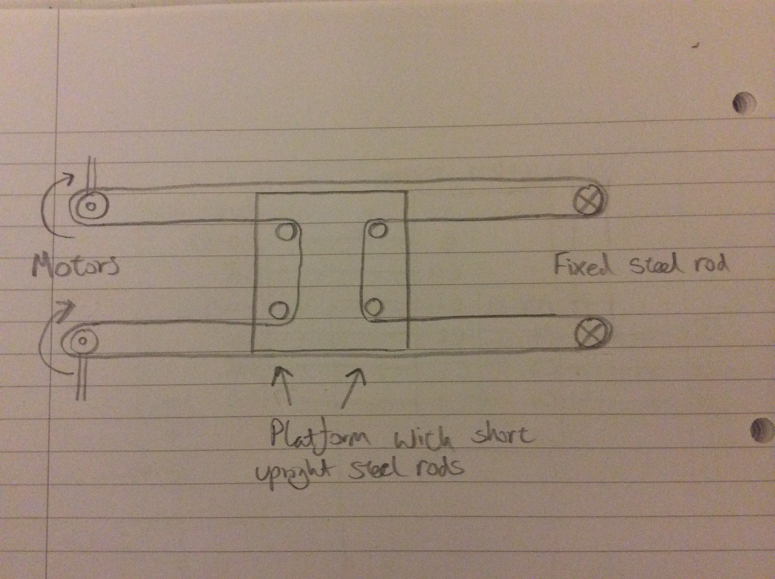
09/13/2016 at 23:10 • 2 commentsThis video shows the mechanism that I thought about using Lego a couple of days ago:
It seems to have several advantages over the platform mechanism that I posted in an earlier log entry. The main advantage is that both motors are at one end, which will make it possible to have two perpendicular axes without the motors getting in the way. It is also easier to tension the thread - this can be done simply by adjusting the position of the steel rod at the end of the rails.
Below is a diagram that helps to explain how it works.
![]()
-
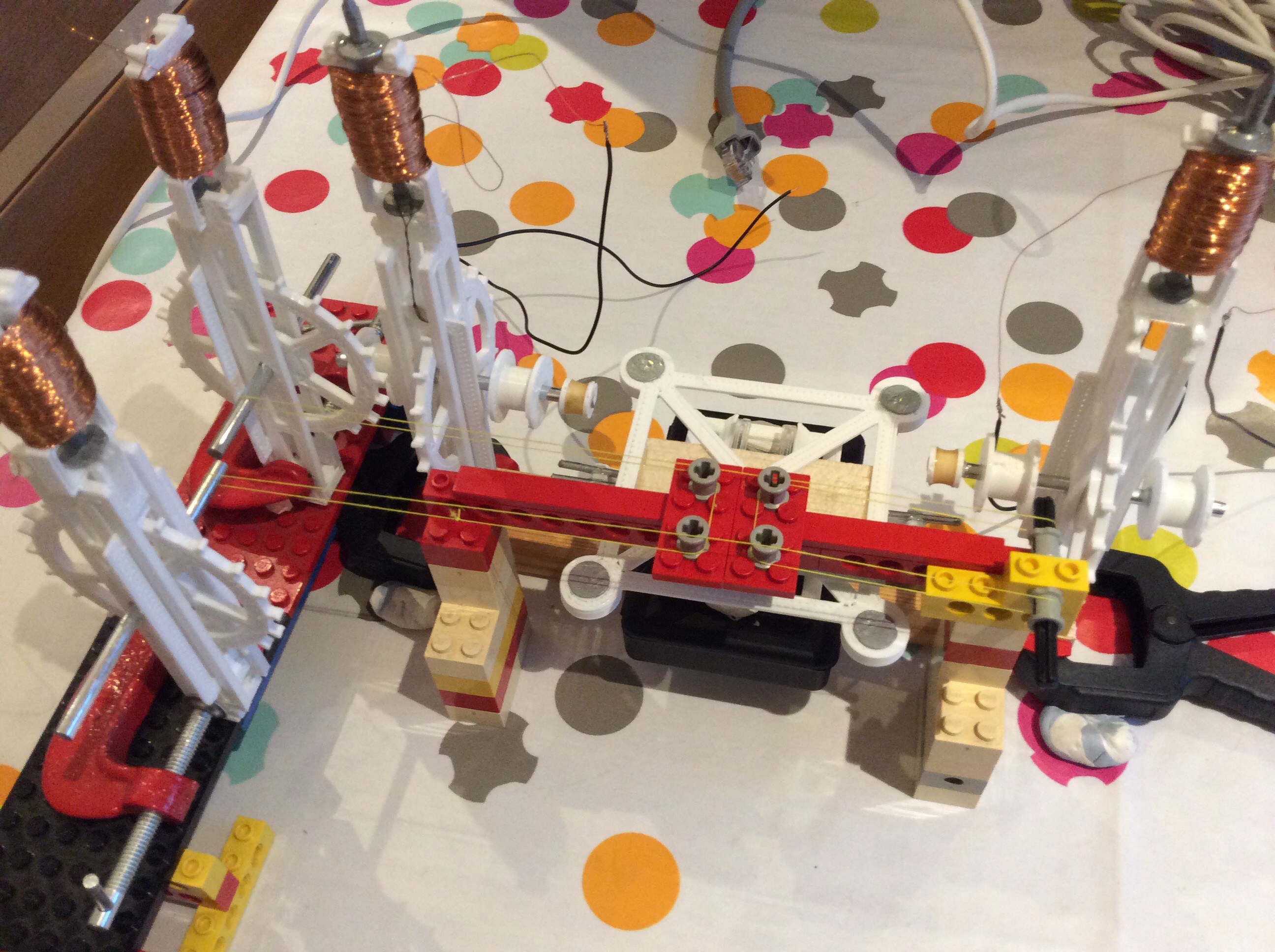
A model to help work out how the X-axis will move
09/11/2016 at 18:58 • 0 commentsThis model shows how the X-axis movement will work, and where the motors driving the X-axis will be positioned. I believe that this mechanism will be better than the one I've been intending to use for the Y-axis (lower friction, fewer parts), so I'll use this for both X and Y
![]()
-
Third version of gravity powered motor
09/10/2016 at 21:35 • 0 commentsThis is a slight refinement of the second version. The length of the motor has been shortened a little (without changing the cog size). In the second version I had glued the two sides of the motor together with the help of off-cuts from old discarded 3D prints, this version has joining components to help snap the two sides together (but they still need gluing). The solenoid nail is now directly connected (glued) to the escapement mechanism, rather than being joined with a thread. OpenSCAD files for this version of the motor can be found here.
The video below shows the motor stepping at about 8 steps per second.
-
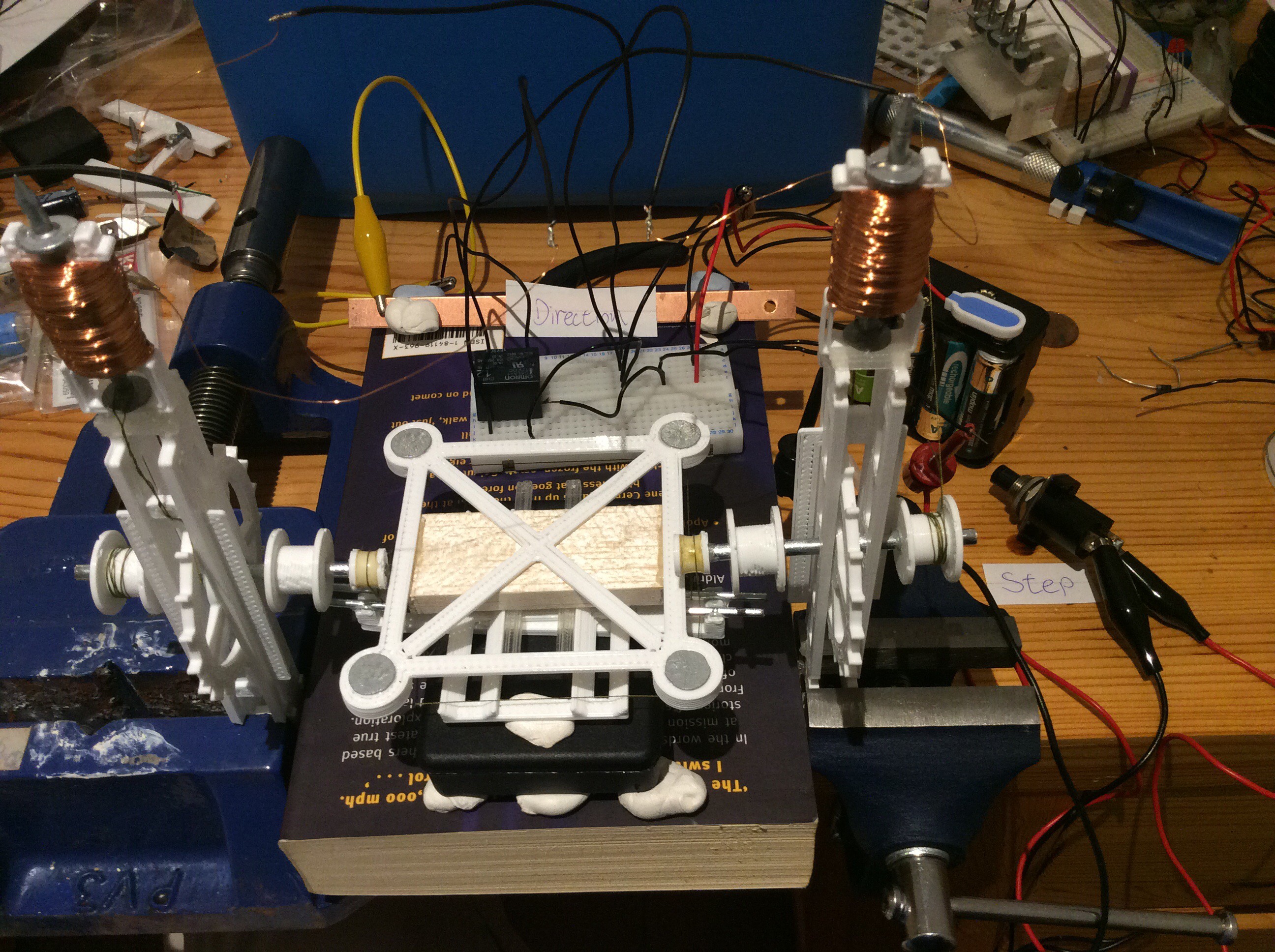
Moving a platform back and forth
09/05/2016 at 22:52 • 0 commentsThe second version of the gravity powered motor that I made last week was good enough that I made a second one and used them to move a platform back and forth. Below is a photo and a couple of videos showing this prototype. I haven't yet drawn a diagram of how the motors cause the platform to move, but you can see a very similar mechanism here: Y-bed motion. Replace the fixed point on the right of the diagram with a second motor.
![]()
A problem with the mechanism is that any small difference in size between the two pulleys that drive the bed will gradually accumulate over time and lead to position errors. I'm not going to worry about this for the time being: I can probably make pulleys with diameters within 1% of each other. I could get better agreement by making lots, comparing them all, and choosing two that closely match. Using a toothed belt or similar (rather than cotton thread) would eliminate the problem, but would add complexity.
-
Second version of gravity powered motor
08/26/2016 at 21:41 • 0 commentsI made a solenoid for the new motor from 1290 turns of 34 swg wire - the earlier version used 40 swg wire. The plastic part and the nail were the same as previously. The coil resistance of the new solenoid was 19 ohms. The solenoid can lift 30g a distance of 6mm when powered from a 12 V source. It doesn't require the additional electromagnet that the previous version used.
The motor will operate with a torque of 2.5 N cm on the shaft, that is about 3 times larger than the largest torque that the previous version would work with. The escapement mechanism will release when there is a larger torque than that, but then slips rather than stopping on the next tooth. This could perhaps be remedied by altering the tooth shape.
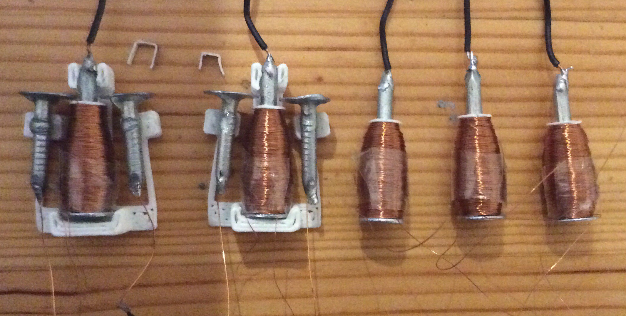
The photo below shows the old and new motors side by side.
![]()
This video shows the motor operating. It is being switched by a homemade relay, which is in turn switched by a relay clock made from two SPDT relays and two electrolytic capacitors.
I came across this very interesting paper about the factors that influence solenoid performance:
A Detailed Explanation of Solenoid Force by Paul H Schimpf
-
Mechanism for gravity powered stepper motor, second version
08/26/2016 at 10:44 • 0 commentsThe video below shows an updated mechanism for a gravity powered motor like the one shown in an earlier log entry. In the new version, the diameter of the cog is 1.5 times larger to give greater leverage, and it is mounted on a steel shaft (part of a tent peg) rather than plastic to reduce friction. The escapement mechanism is more loosely fitting to prevent it from jamming. It feels lighter to operate. Now I need to make a beefier solenoid and attach it.
-
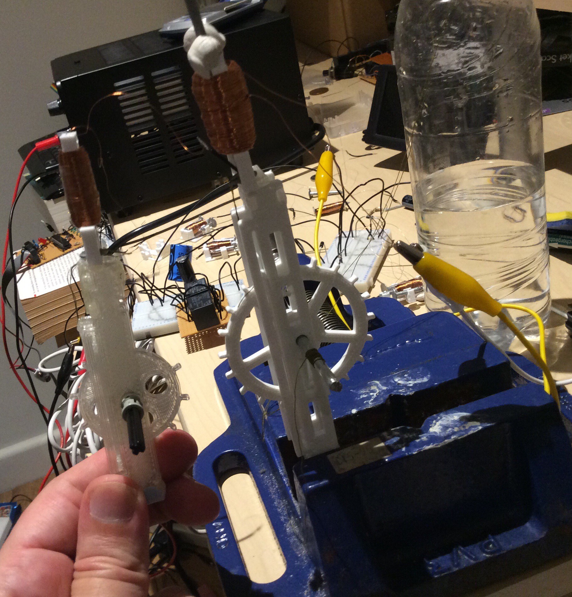
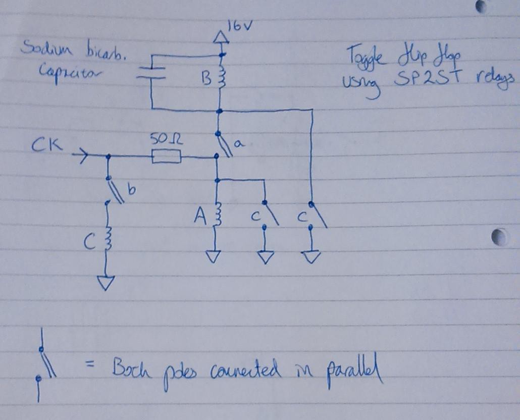
Toggle flip flop using 3D printed relays
08/21/2016 at 21:32 • 0 commentsHere is a rather uninteresting video showing a toggle flip-flop driven from an approx 1.5Hz signal toggling for 5 minutes:
Here is a circuit diagram:![]()
The clock signal comes from a clock circuit made from a pair of off-the-shelf SPDT relays (off to the right of the video - the two electrolytic capacitors are part of the clock circuit).
The circuit fails to toggle at 1:36 and again at 4:00. I'm not sure yet whether the failure is due to bad circuit design or problems with the relays, or a mixture of both. The way that it fails is that relay A doesn't turn off when it should - one of the pole nails remains in contact with the coil nail. I can think of several reasons why this could happen - further work is needed to find the problem.
The reason why toggle flip-flops are relevant to this project is that the control circuit described the file 'controller_explanation.pdf' in the 'FILES' section of this project is based around them - the largest part of the control circuit consists of four toggle flip-flops configured as a divide by 3 and divide by 4 counter. A version of this circuit using off-the-shelf DPST relays can be seen here.
RelayRepRap
This project is about exploring whether it is possible to make a RepRap control system that can be made by a RepRap.