Yiğit Topcu
-
Final Demo and Further Improvements
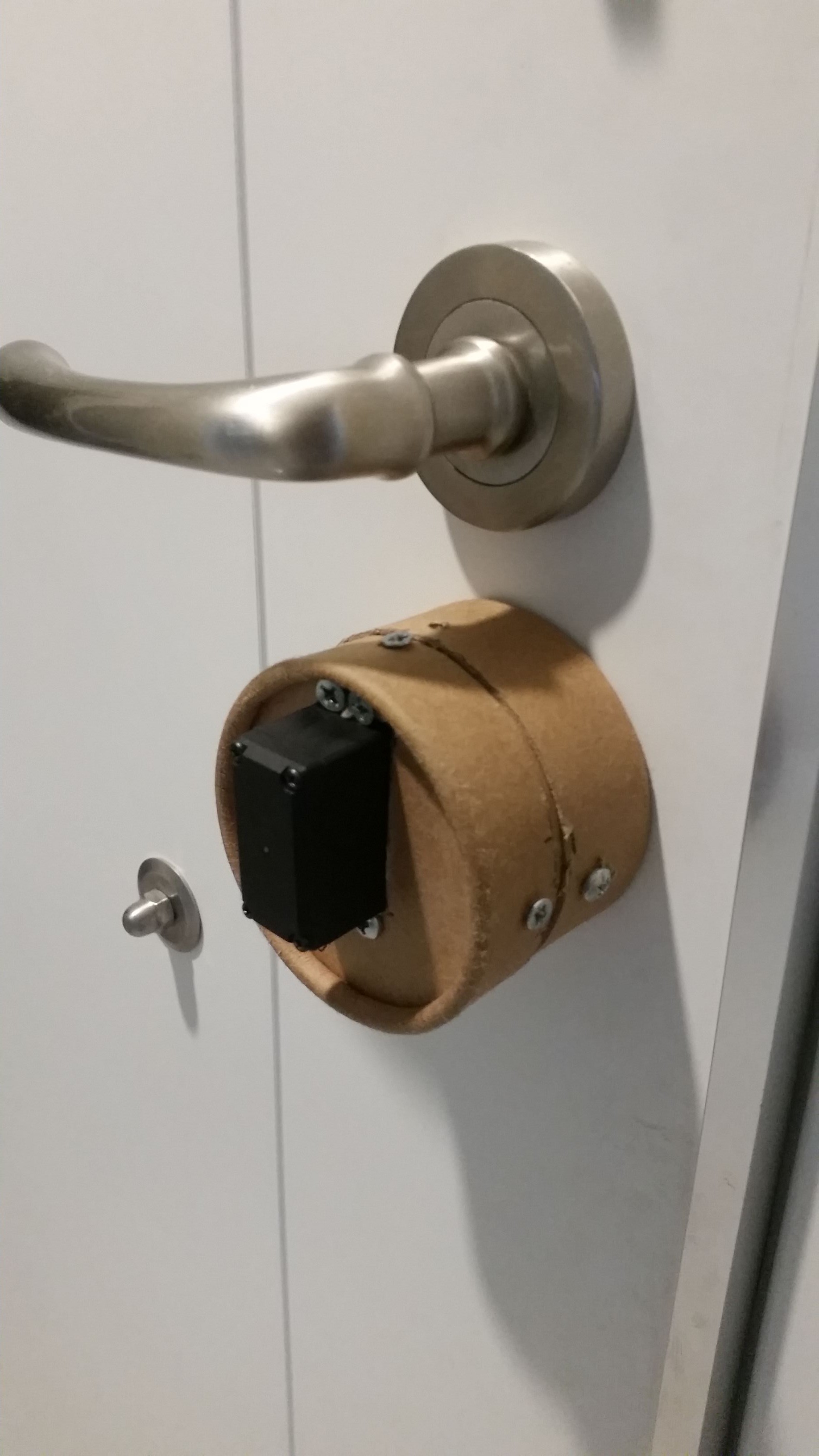
05/30/2016 at 00:14 • 0 commentsAfter I've finished the build, I attached my device to the door and made some miner adjustments on threshold values. It looks like ACS712 output voltage depends on it's input voltage. Since USB voltage is lower than 5v, when I powered the device with a regulator, output analog value increased. So I re calibrated my sketch to work with 12v input of the device.
Both Web App and led interface needs some improvements but it still enough functional for first build. Also enclosure need some white paint on become a nice fit for my door.
Further Improvements
- LED interface and Web App UI needs some attention
- Enclosure is pretty damaged after too much testing and calibration. I need to replace it.
- Diffuser affected from the heat of the ESP8266. I need rebuilt it with less layers of material.
- Electronics still takes too much space and also consume too much power. I can use an Esp-07 module to gain some space.
- Bluetooth is needed to automatically trigger unlock when I am close to the outside of the door.
- I need a more secure method from just a pattern lock. I think OTP is the right way secure a device like this.
-
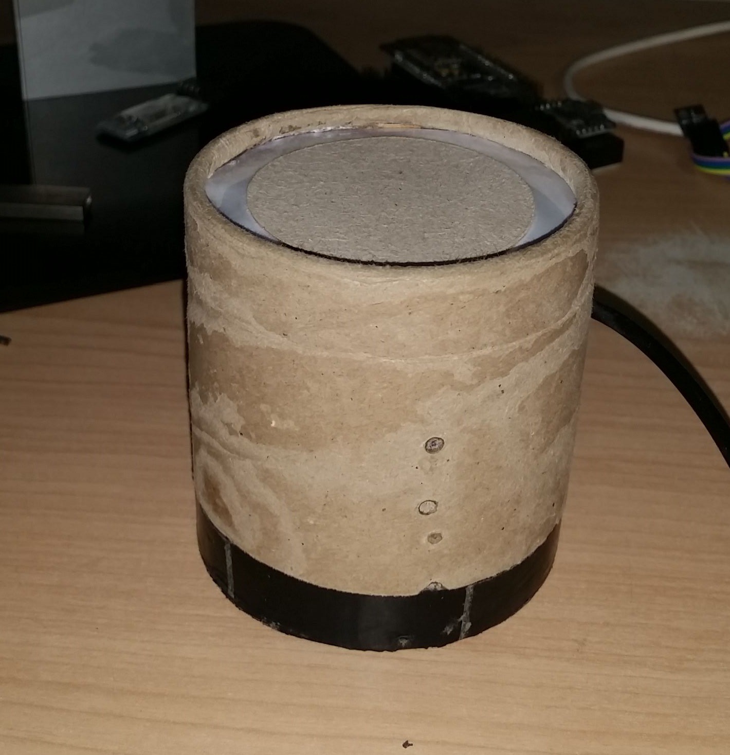
The Enclosure and Elecronics
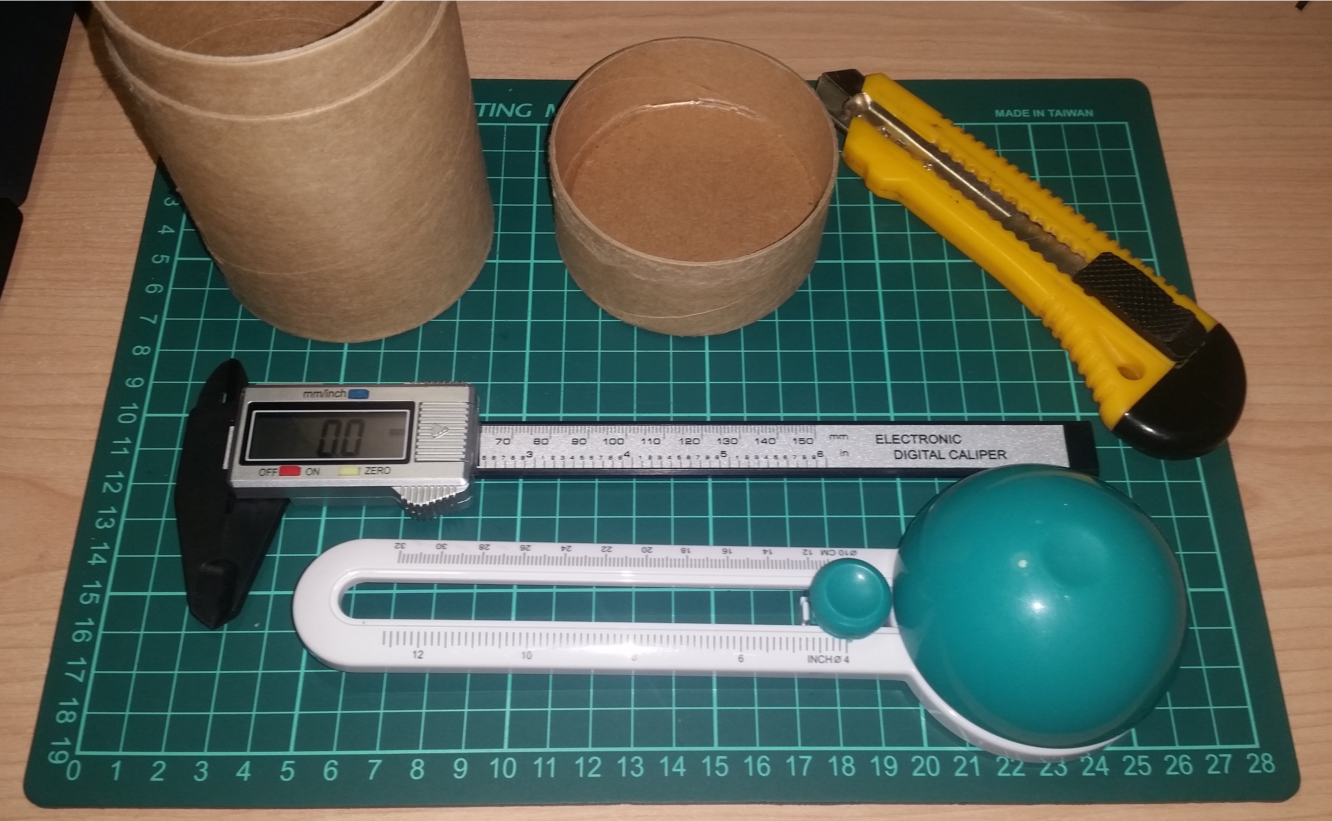
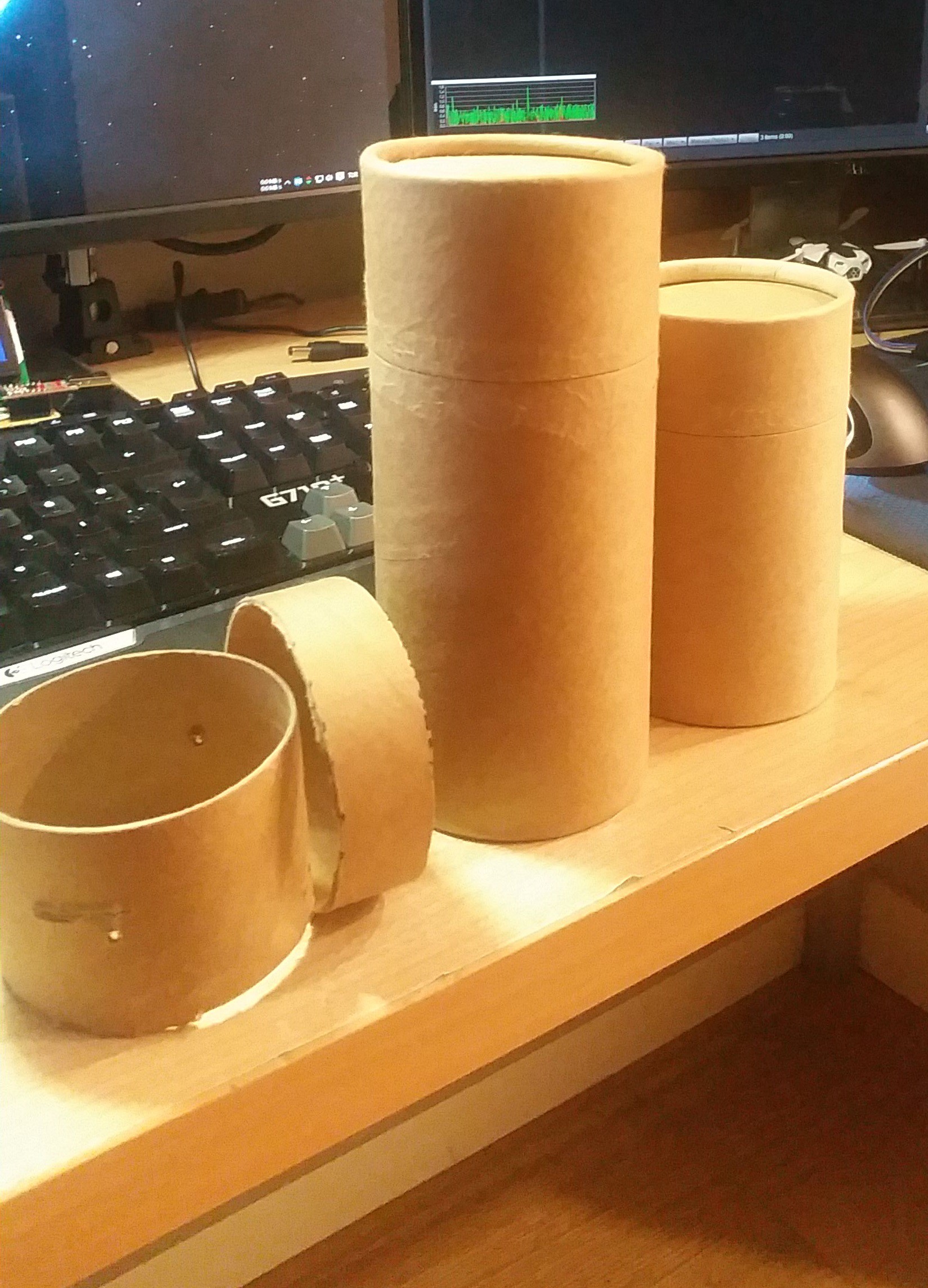
05/29/2016 at 23:46 • 0 commentsI've already made a decision to the building material while I was testing the servo on my second project log. Cardboard is the easiest material to work on. I can use household tools to cut and shape the material. The only custom tool that I need is circular cutting tool.
![]()
![]()
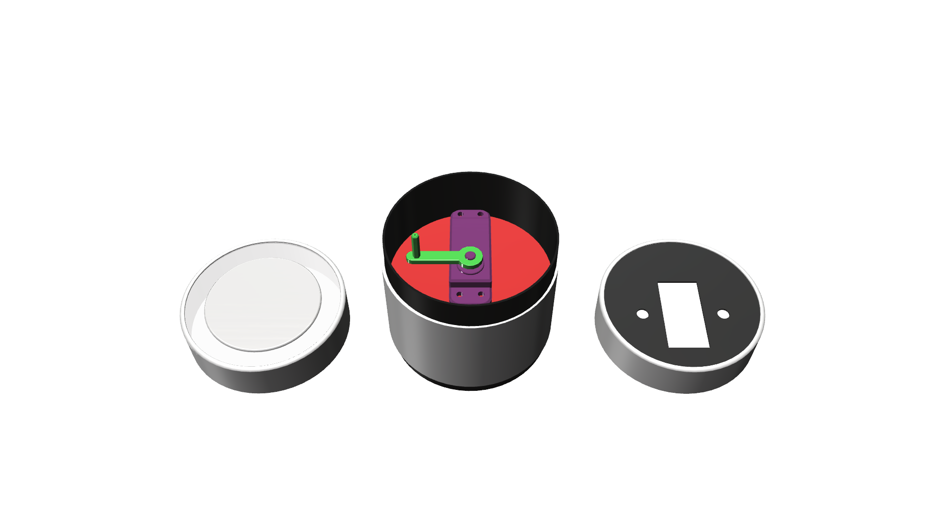
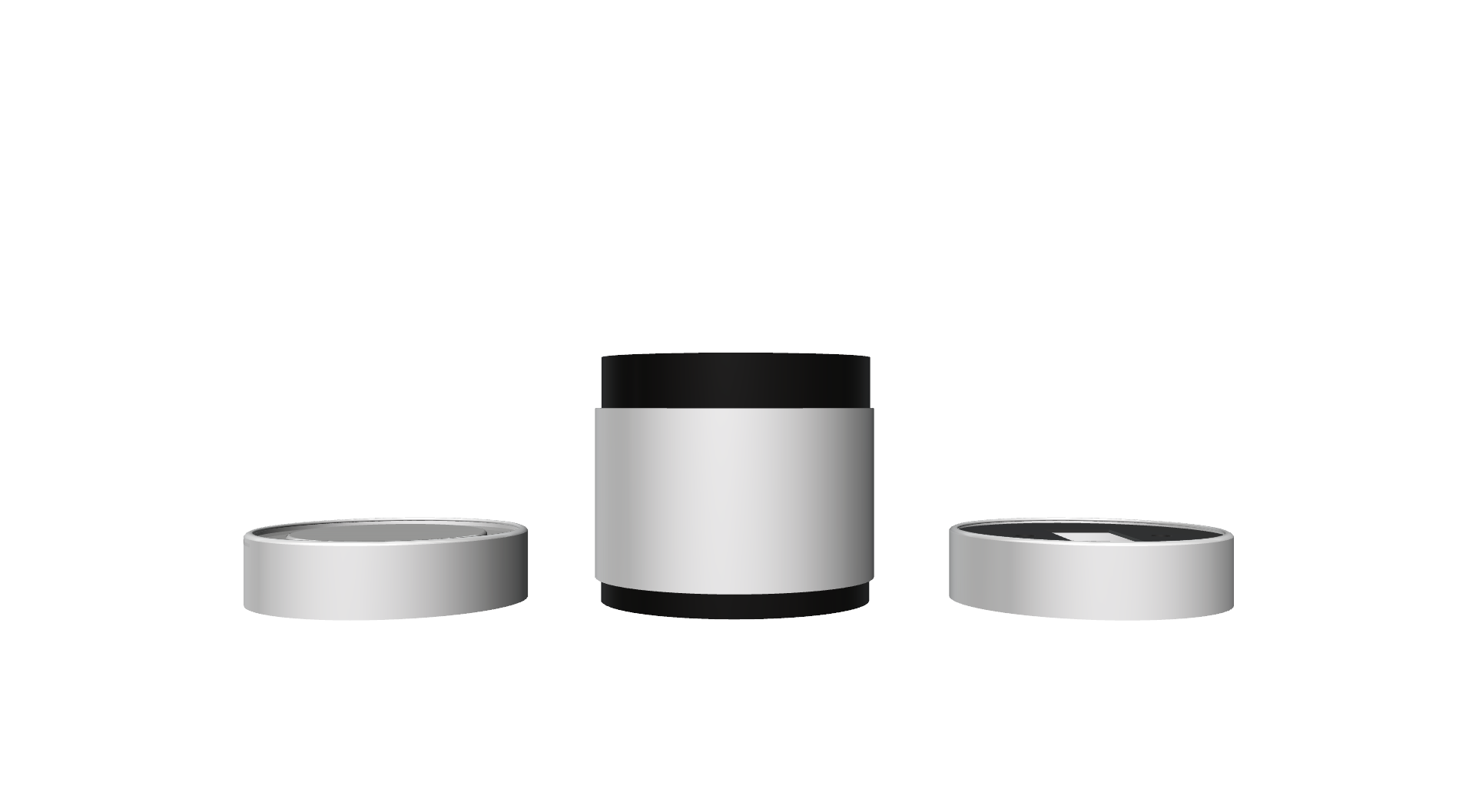
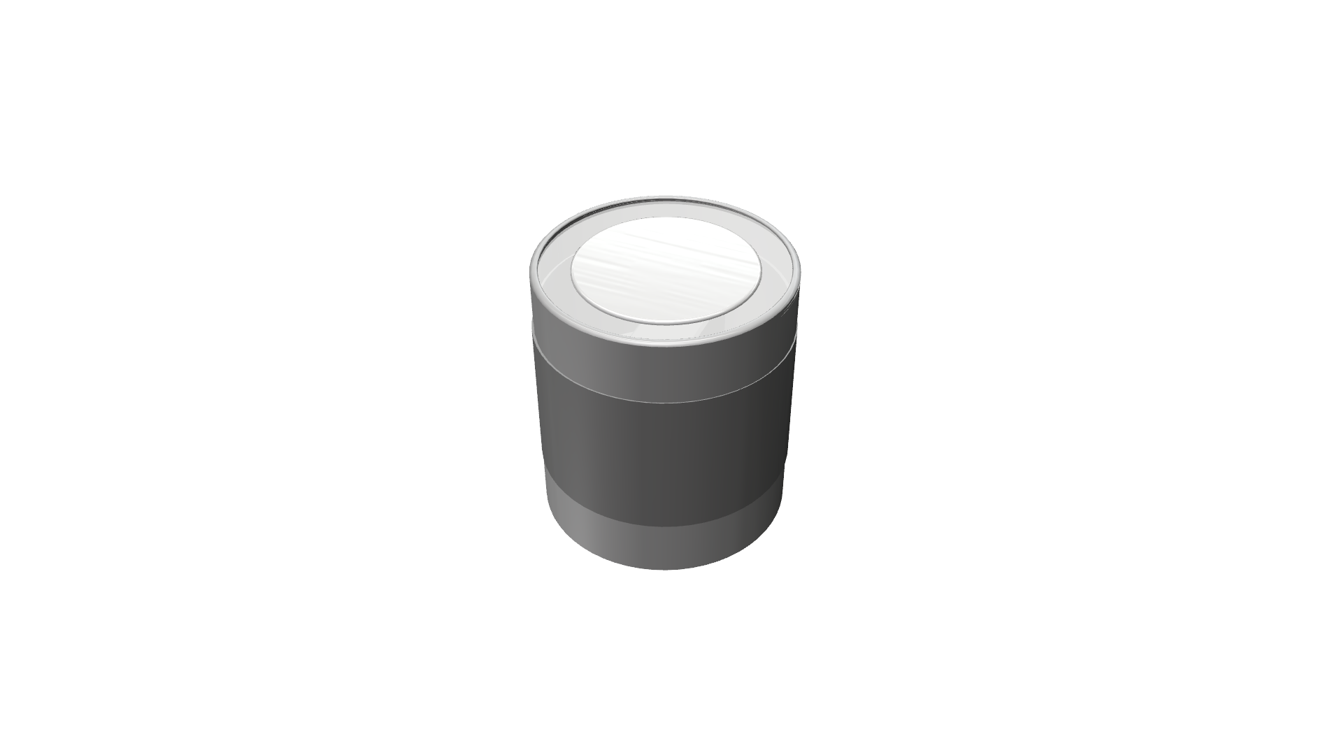
The Design
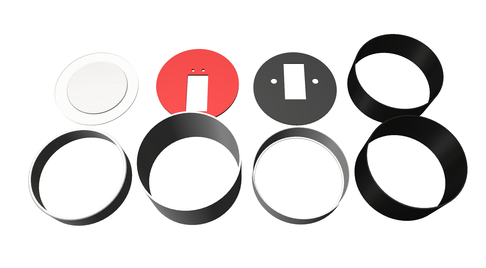
Enclosure must be a close box and there mustn't be any visible cables on the servo itself. I designed the enclosure with 9 unique parts. And Its about 790mm x 960mm.
- Diffuser
- Top Cap
- Middle outer cylinder
- Top inner cylinder
- Servo holder ring
- Bottom inner cylinder
- Bottom cap
- Door mount disk
![]()
![]()
![]()
![]()
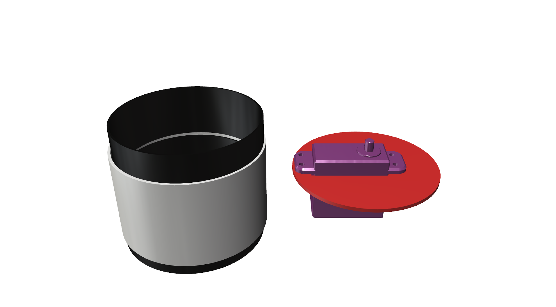
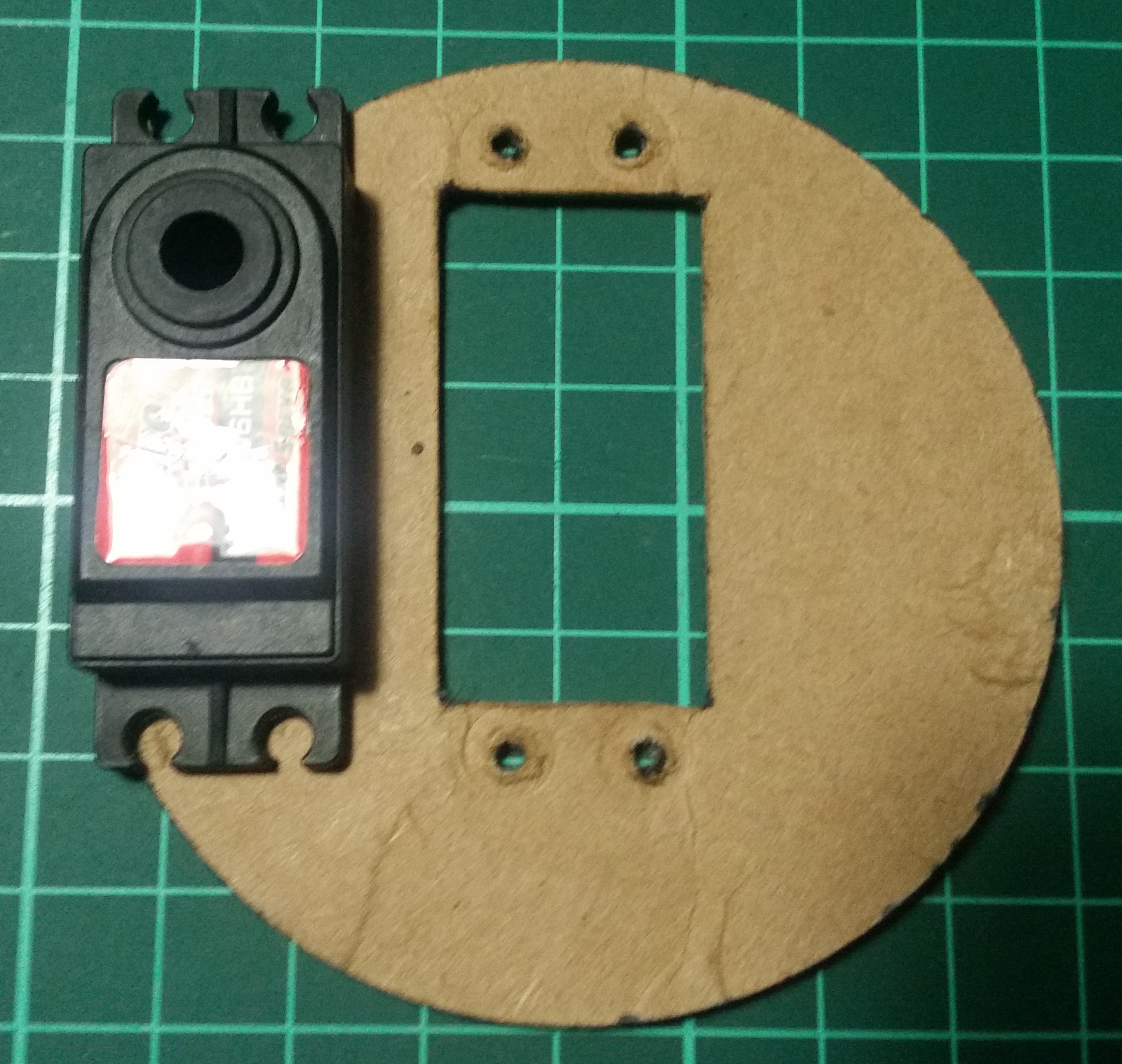
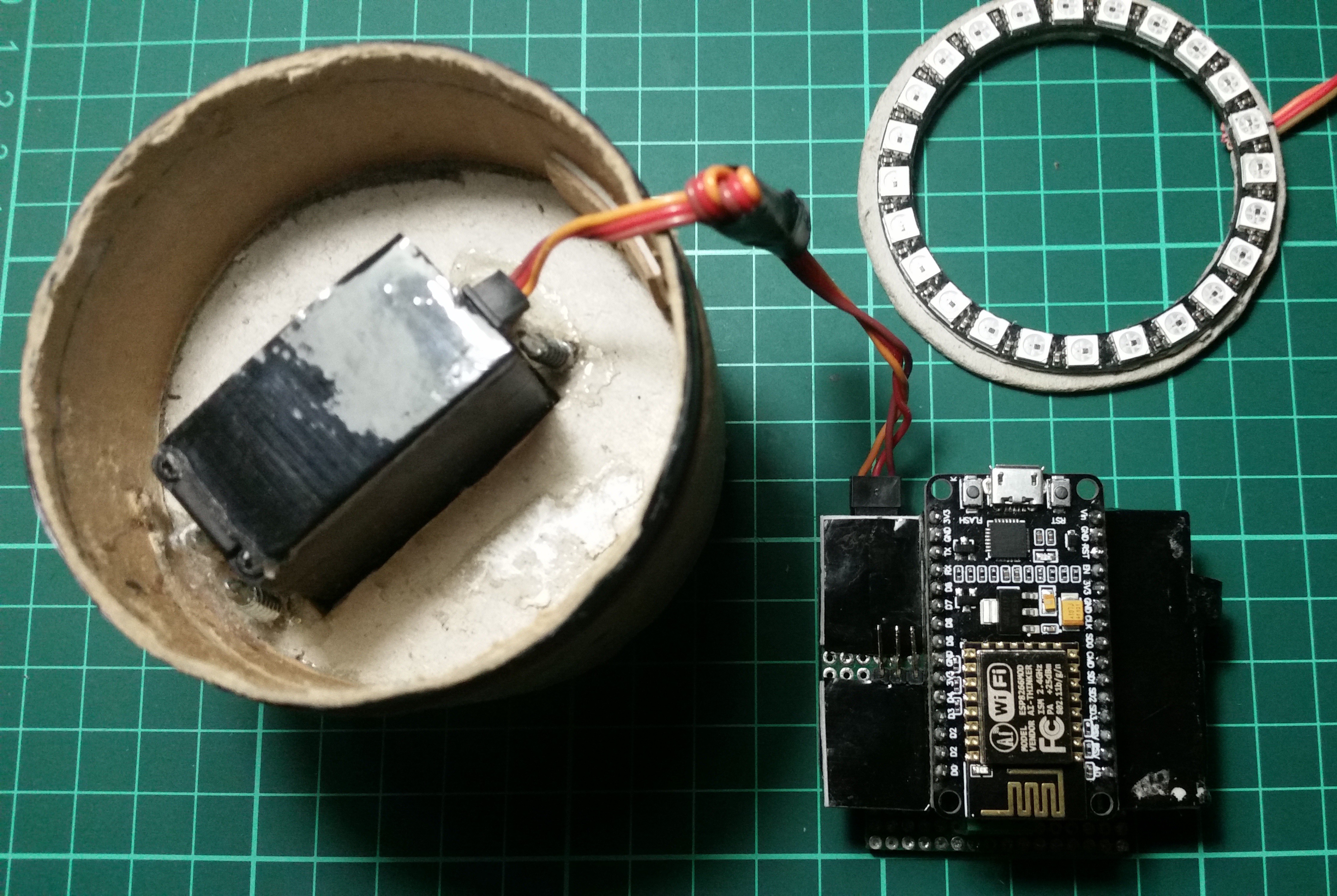
Attaching the servo
I used the servo shell as template while I'm cutting the servo holder. And I have used the inner cylinder to hold this servo holder disk.
![]()
![]()
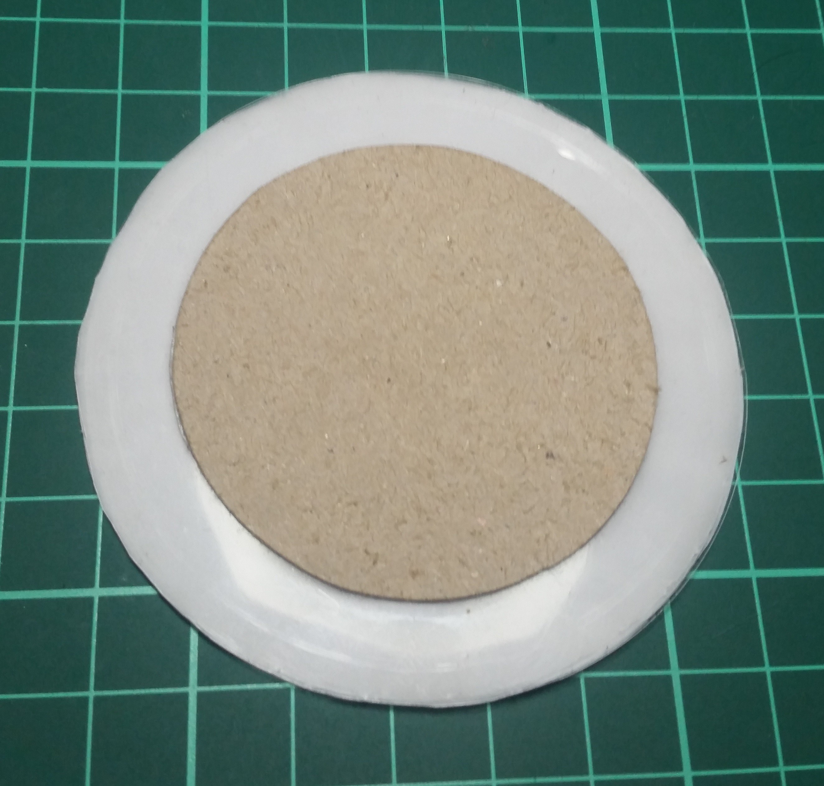
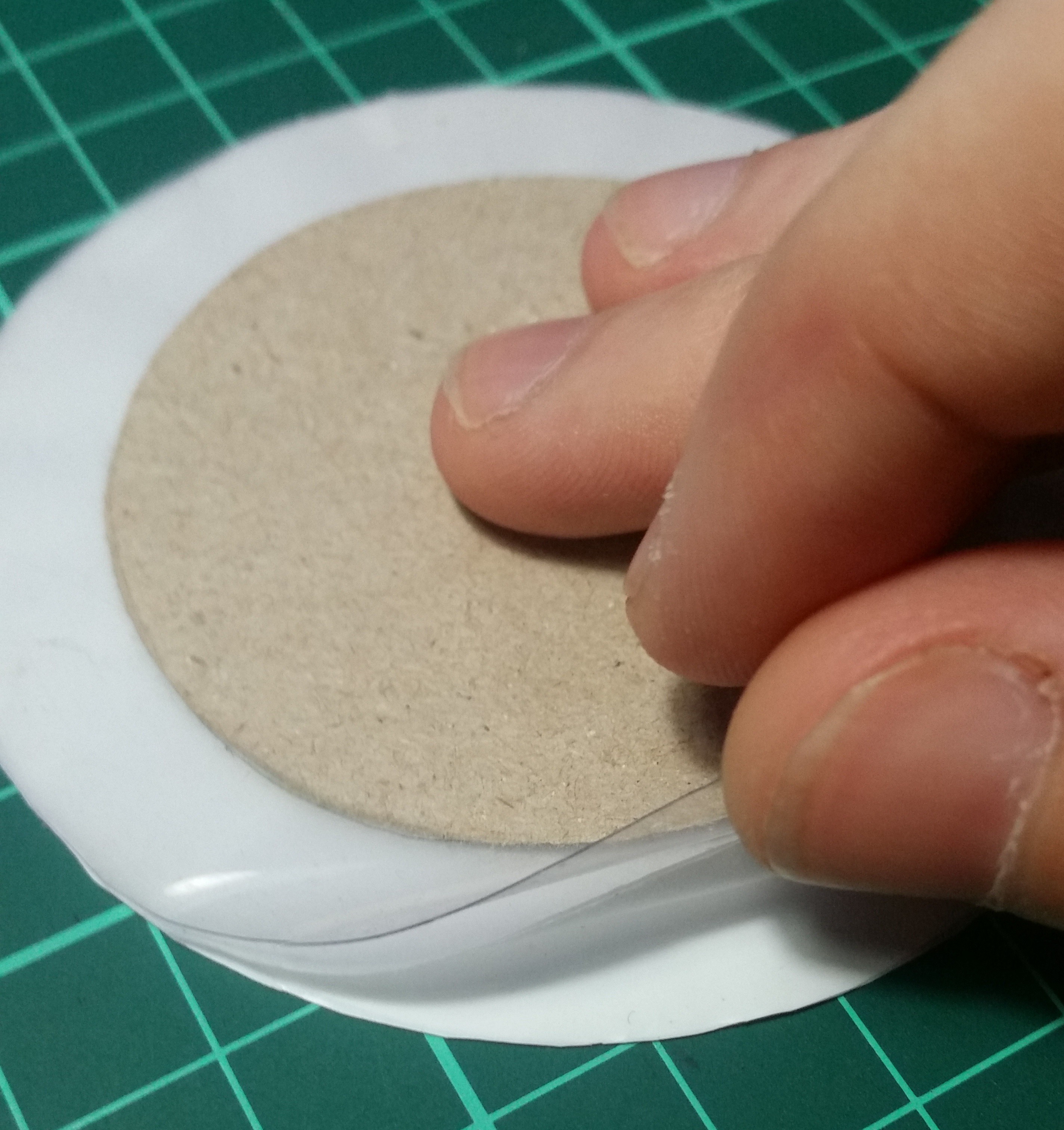
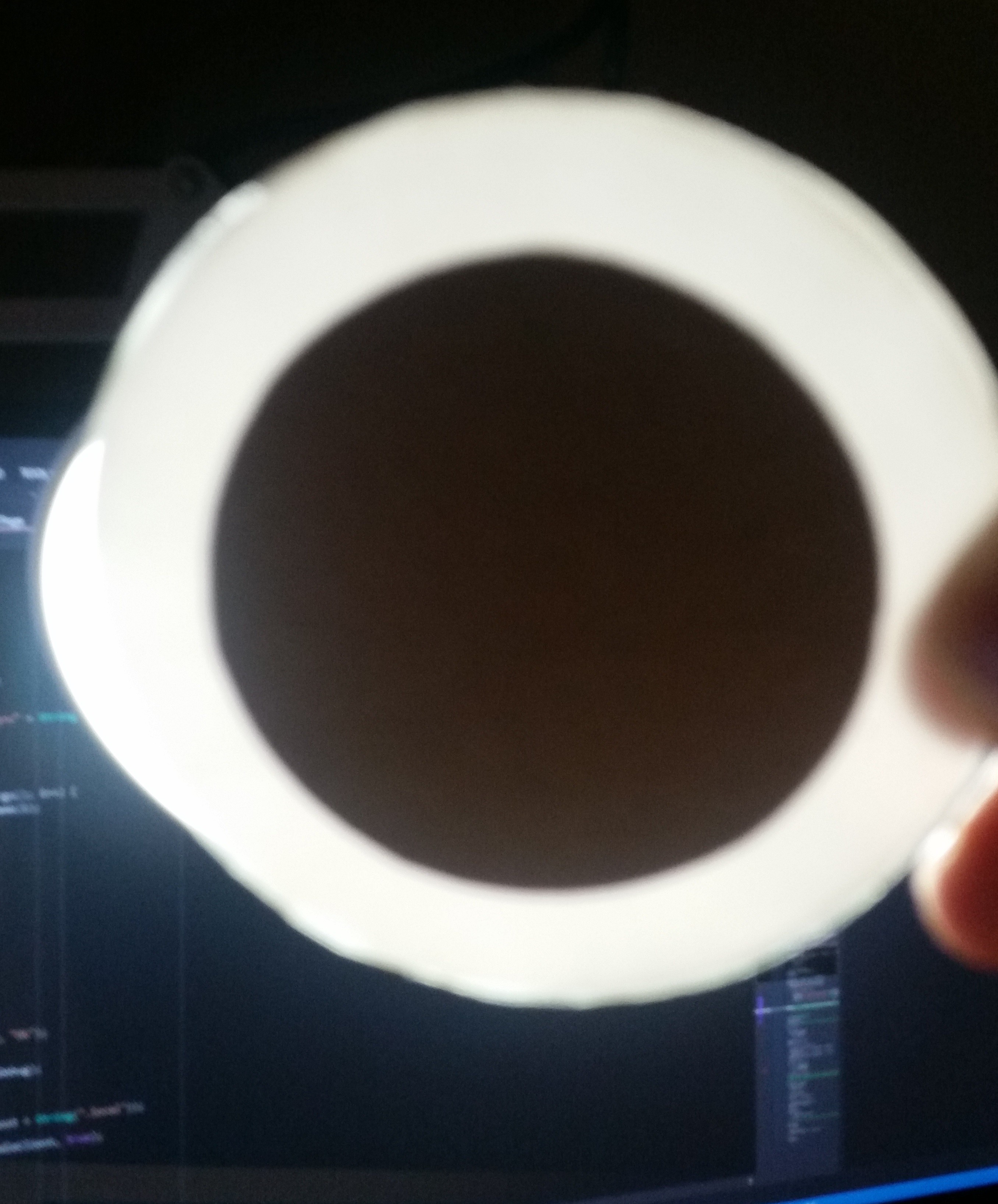
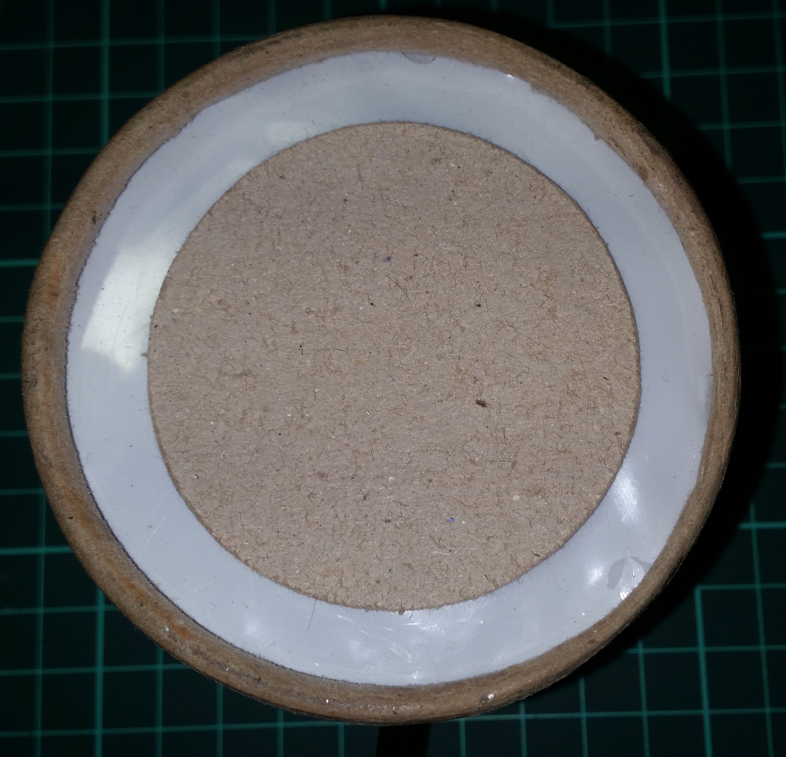
The Diffuser
I think the diffuser was the hardest part of the enclosure because you can't actually measure or decide how light acts on a transparent surface. Trial-and-error was the only way to build something like this. I do not want to see the individual LED's inside the box so I made a six layered transparent disk to spread enough light. Disk contains two full transparent layers both side. There are multiple plastic and paper layers at the bottom of clear layers.
![]()
![]()
![]()
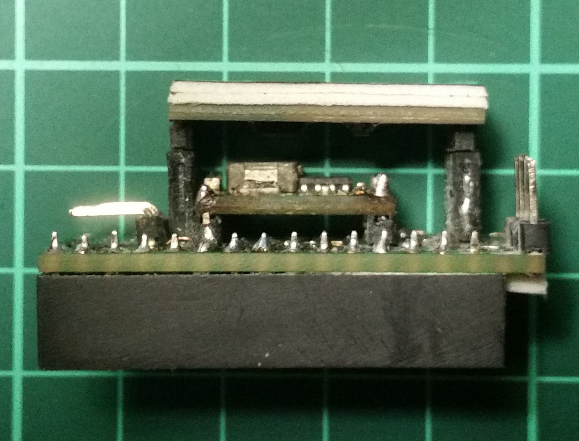
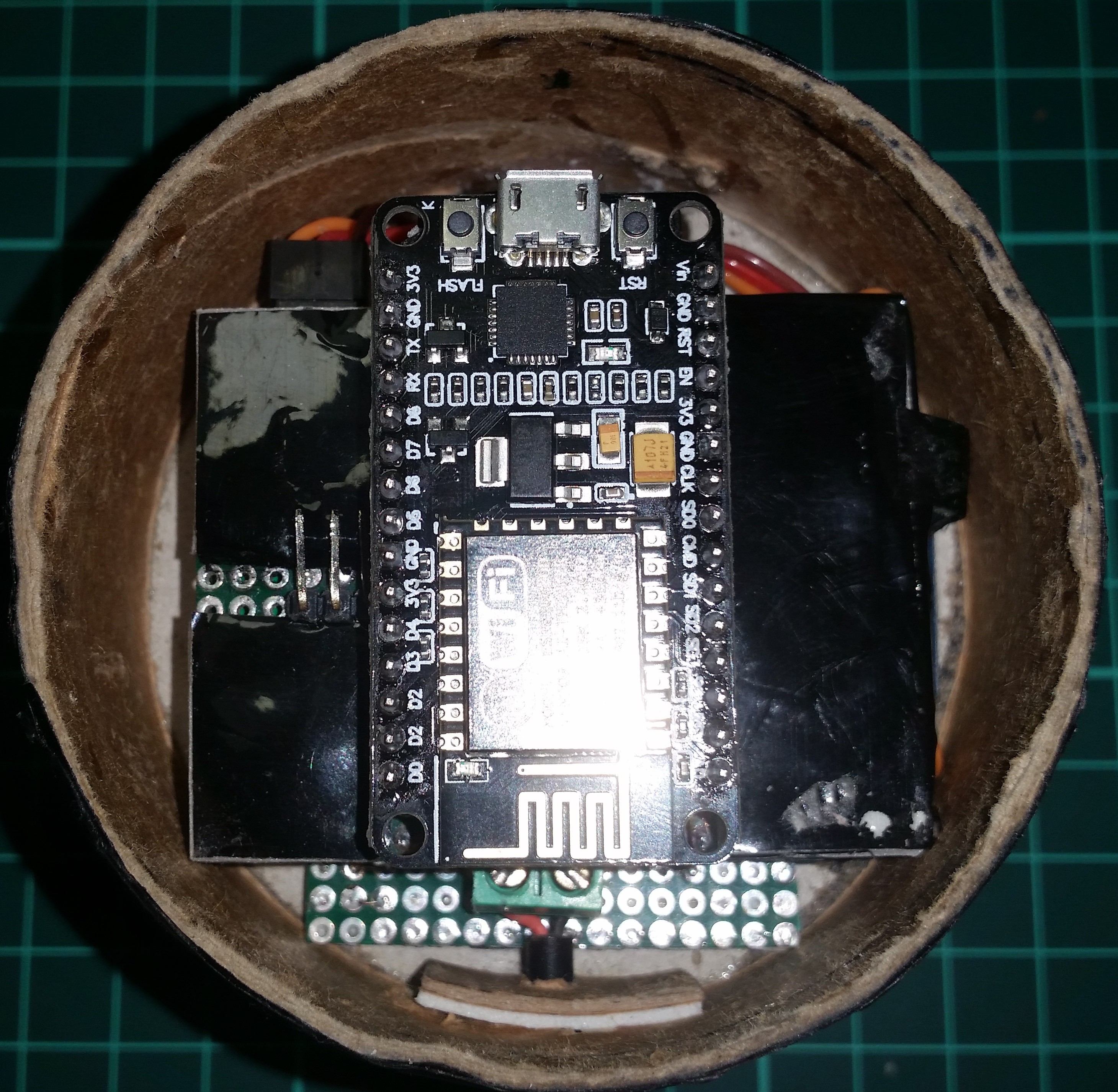
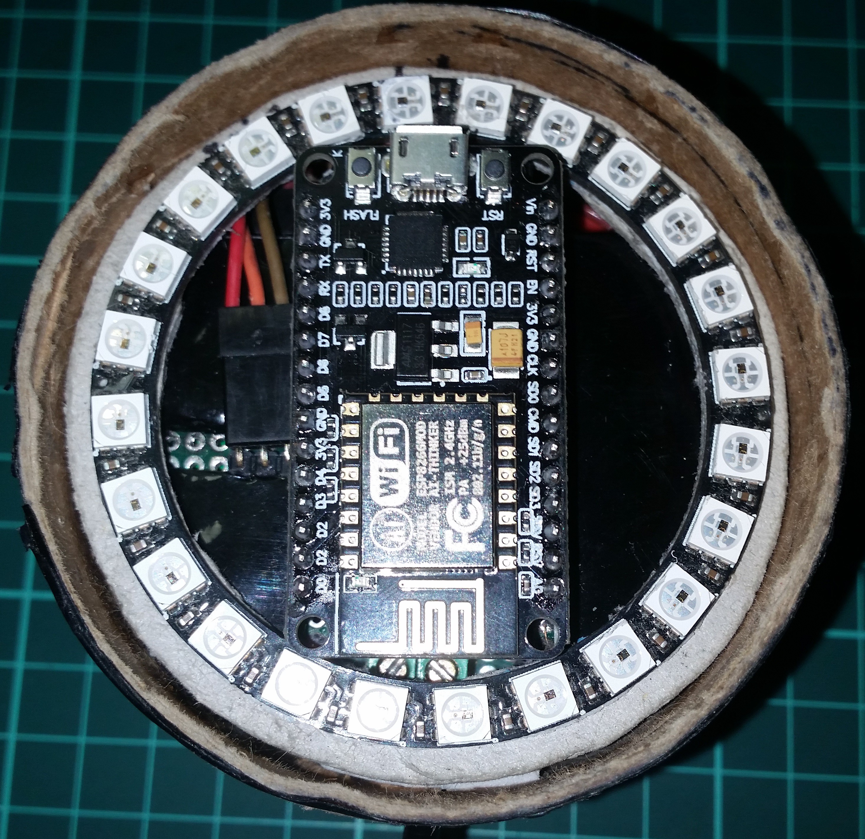
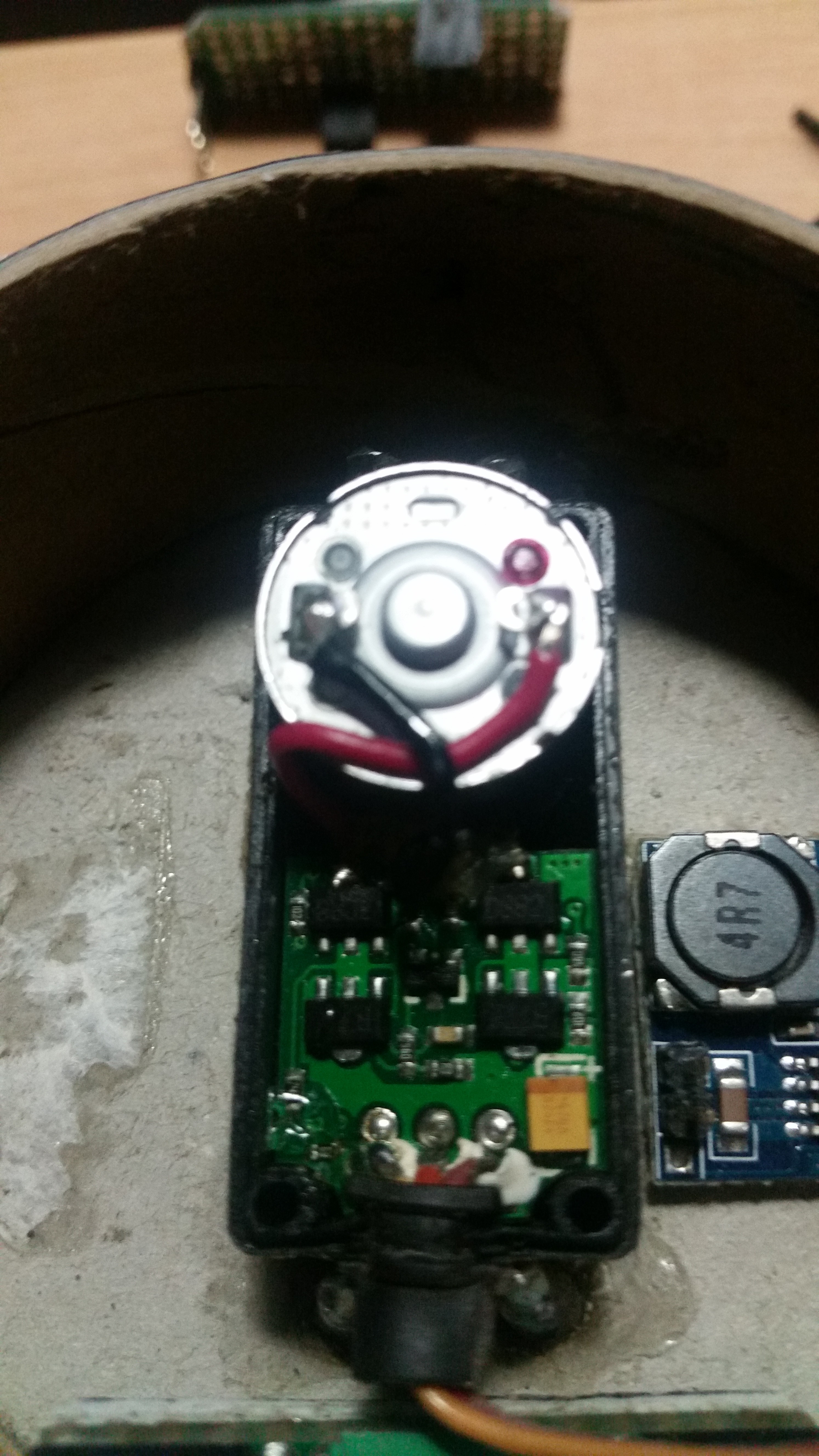
Electronics
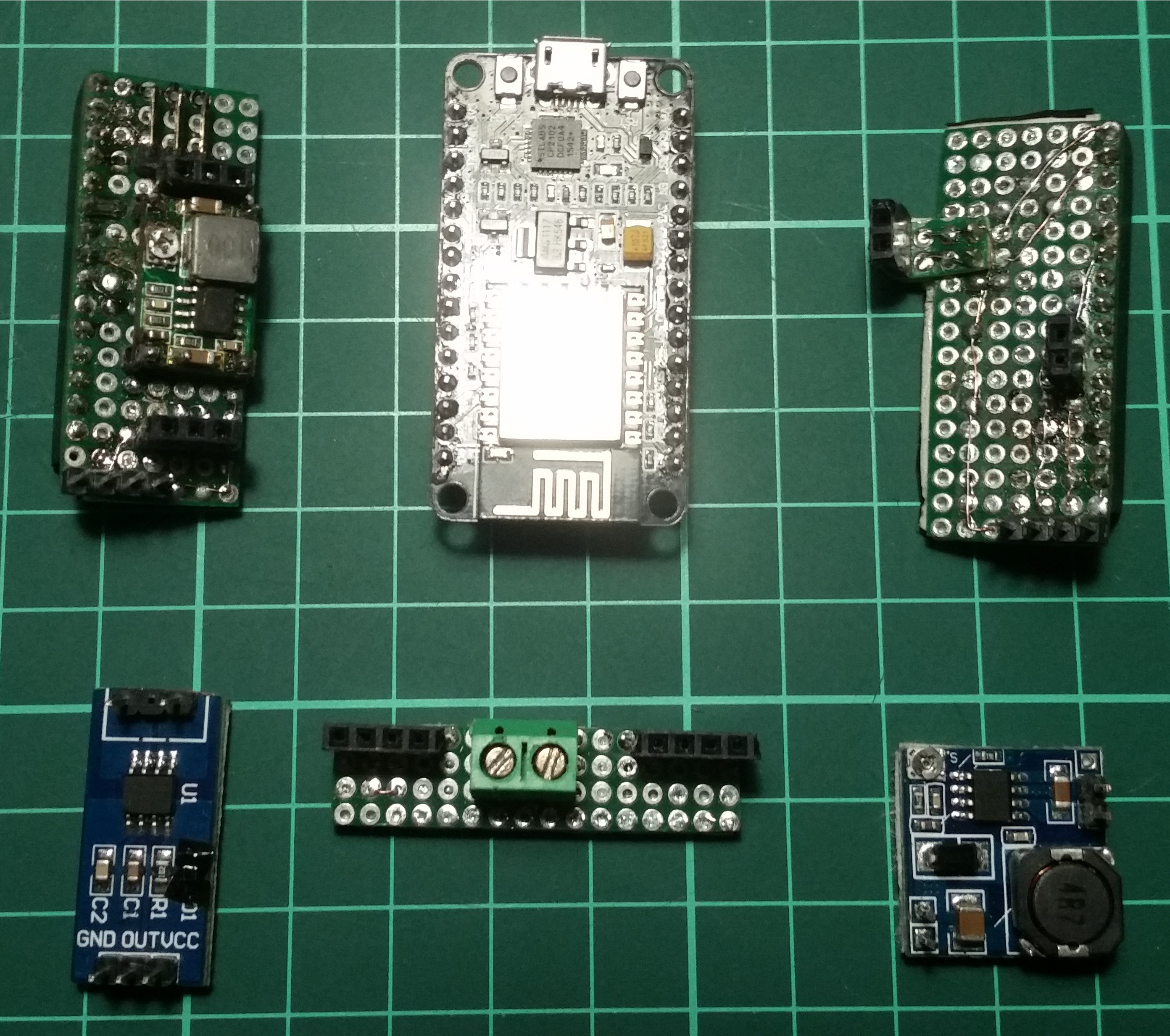
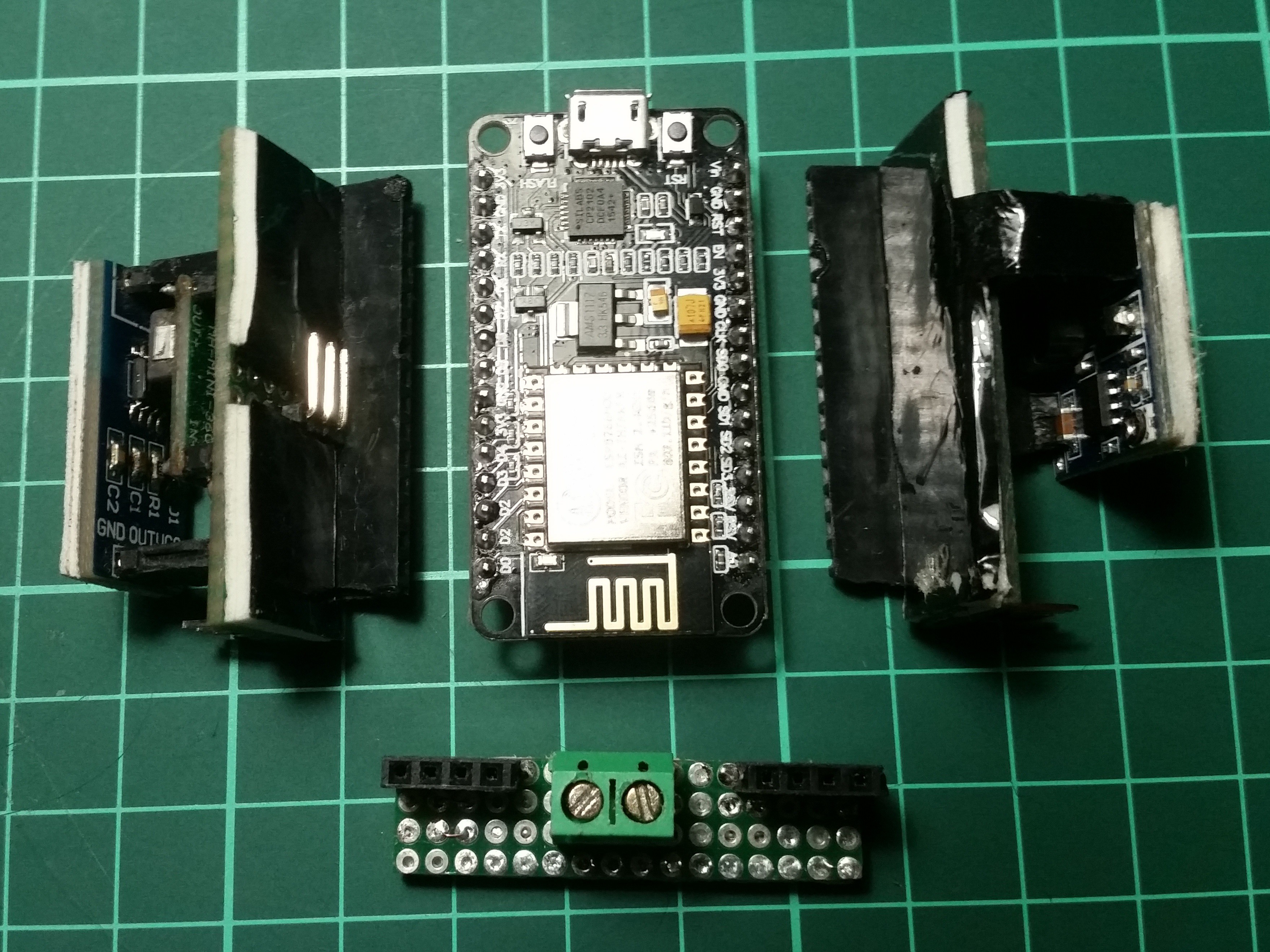
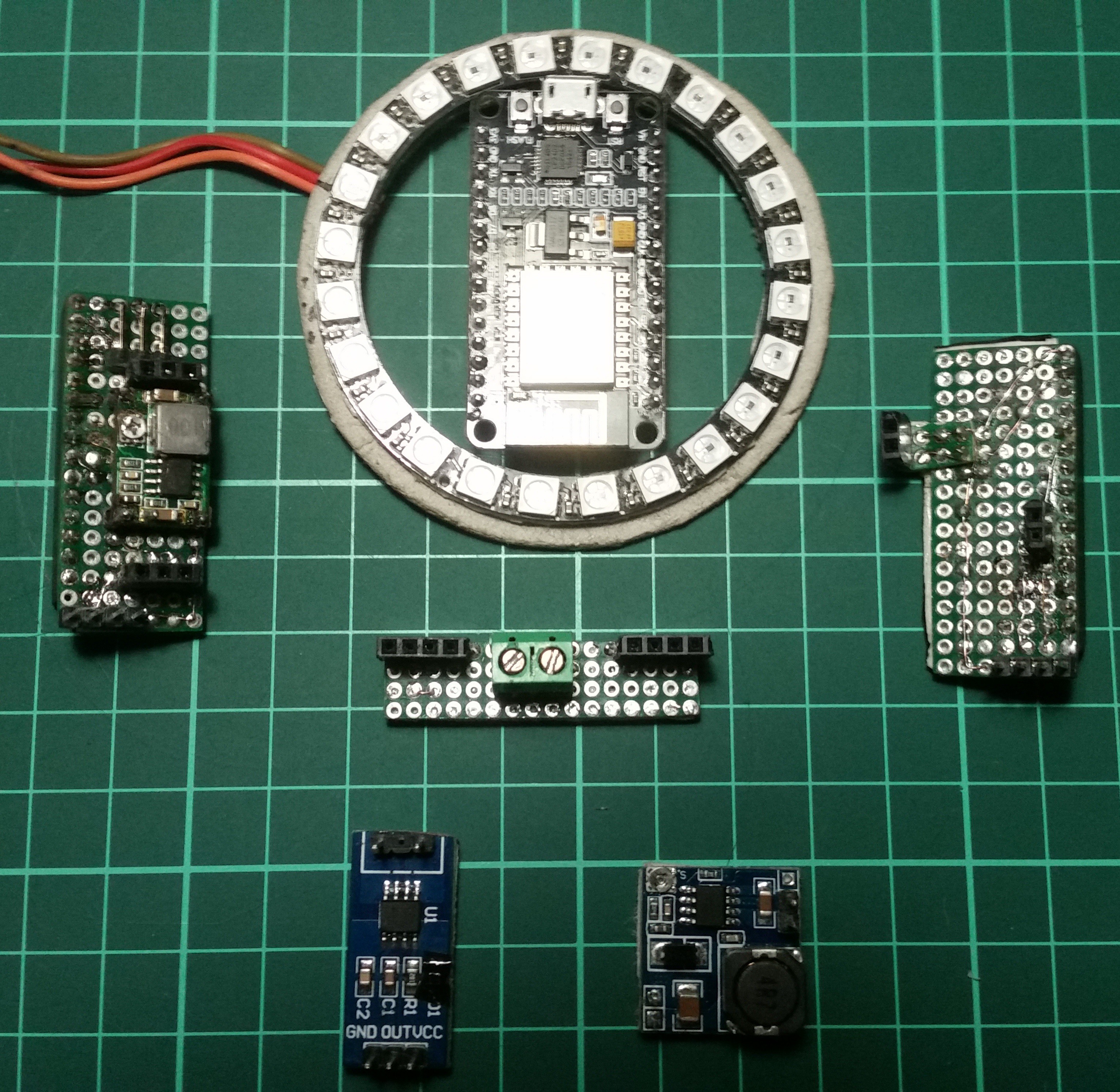
When I've mounted the servo, I've realized that there was not much space to put electronics in it. So I made some custom design by using standard prototype boards. I made the whole system modular so that I can replace or modify anything without building a new custom board. Basically whole board contains 7 different modules.
Device is powered with a 12v input and it has two step-down regulators on it. One of them is set to 6v for servo and the other one outputs 5v for NodeMcu. And also there is another regulator on the NodeMcu for 3.3v requirement of the ESP8266. I know that is too inefficient but I will fix it on the next version of the device.
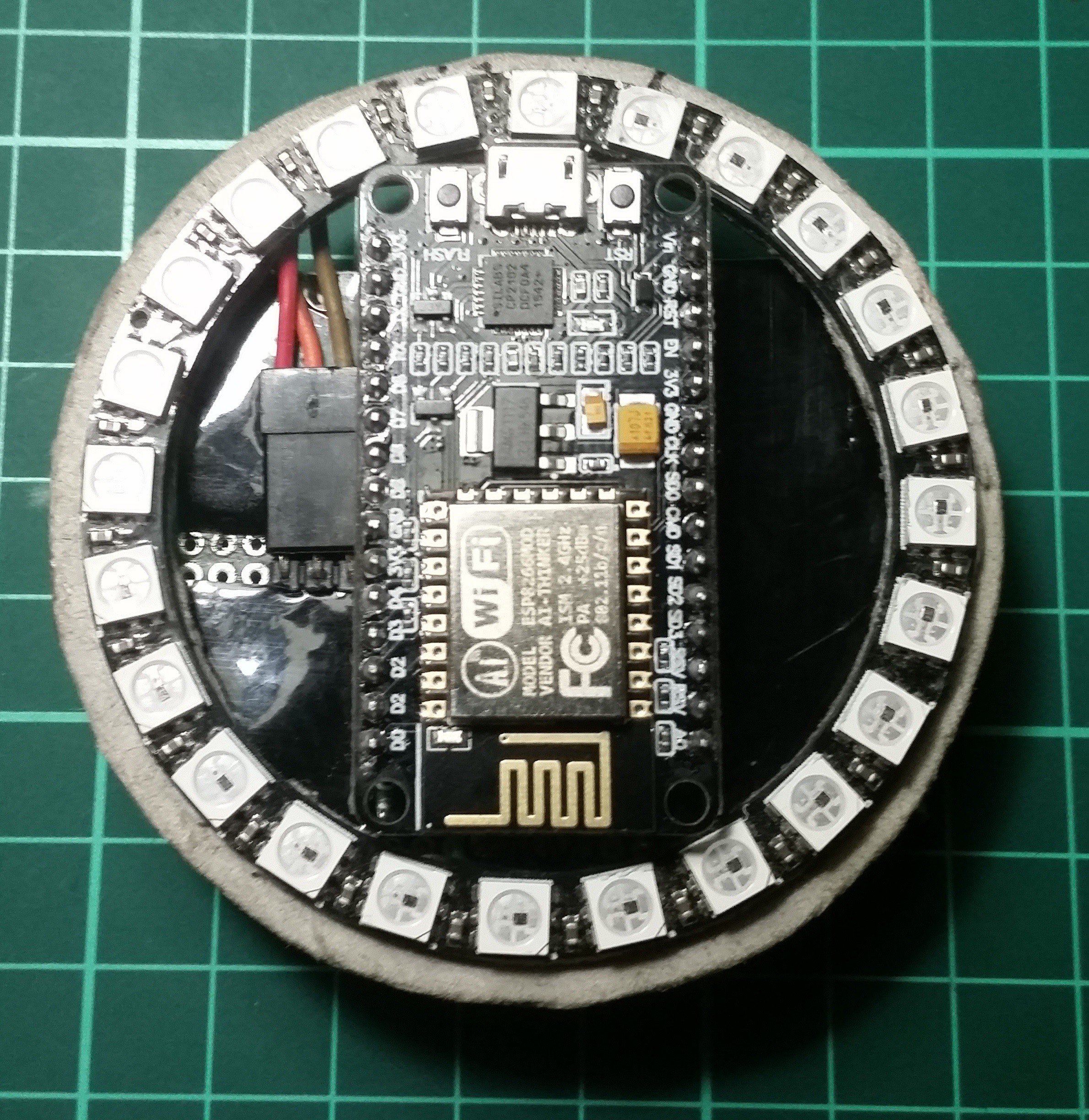
- NodeMcu DevKit v1.0
- 24x RGB WS2812B led ring
- ACS712 current sensor
- Sensor board with servo regulator.
- Voltage regulator board for NodeMcu and crrent sensor
- Power distribution board
![]()
![]()
![]()
![]()
![]()
![]()
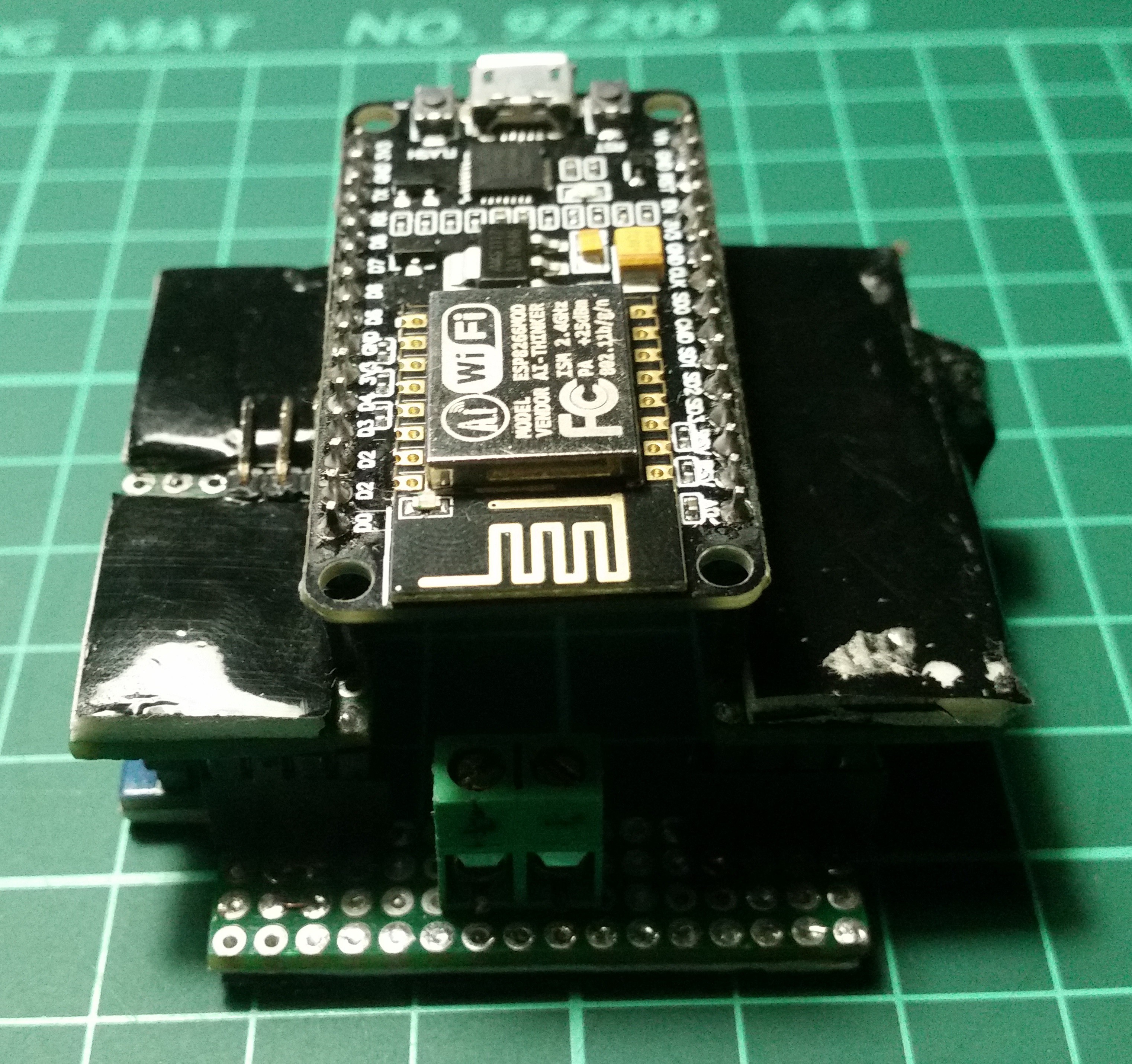
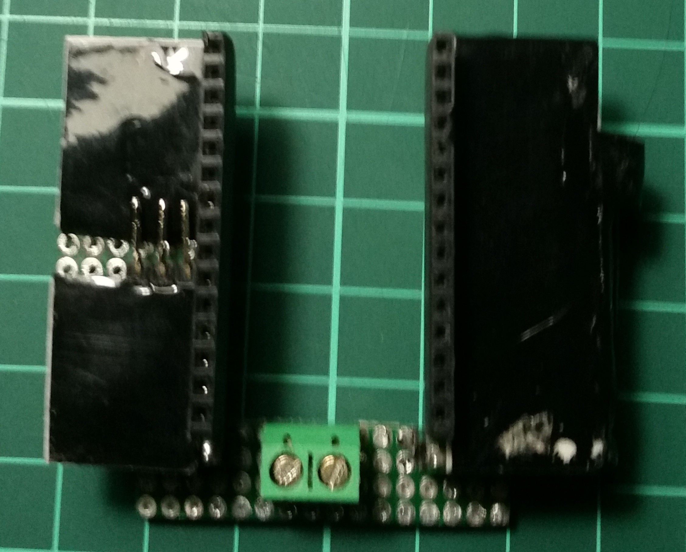
Final Assembly
![]()
![]()
![]()
![]()
![]()
![]()
![]()
-
Software And UI
05/29/2016 at 22:27 • 0 commentsAfter I've destroyed the most expensive part of my project, which was the servo, I've decided not to run any tests before I finish building the software. I use Visual Micro on Visual Studio as the development environment with Arduino IDE on ESP8266. You can find all the code in my GitHub repository.
Double Current Threshold Algorithm
When I was testing the current sensor, I've realized that there were two different thresholds. When the lock cylinder reaches at the end of mechanism, servo forces to stop and draws much more current compared to the current drawn during locking or unlocking the door. I found out that I can use the second high threshold value to determine the locks last state. And also lock will fix it's last state automatically.
![]()
User Interface
I've built a responsive HTML page as the user interface of the device. Browser connects to the web socket service which is hosted on the ESP8266. Than I've built a small hosted web app for my android device.
And also, I have added a pattern lock for providing built-in security. Pattern generates a password and app uses this password to authenticate with the web socket service.
![]()
![]()
![]()
-
Destroyed The Servo With a Success
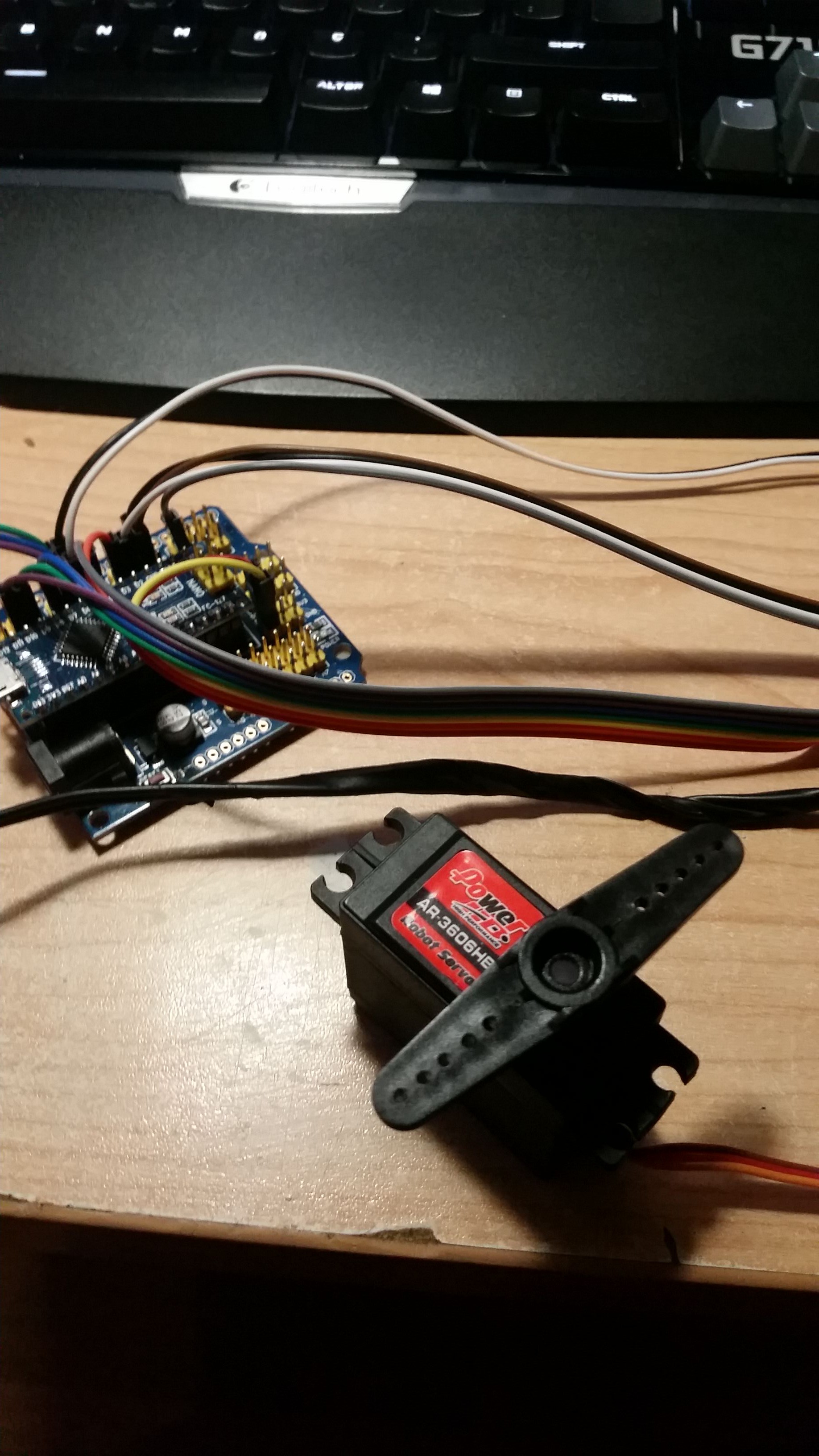
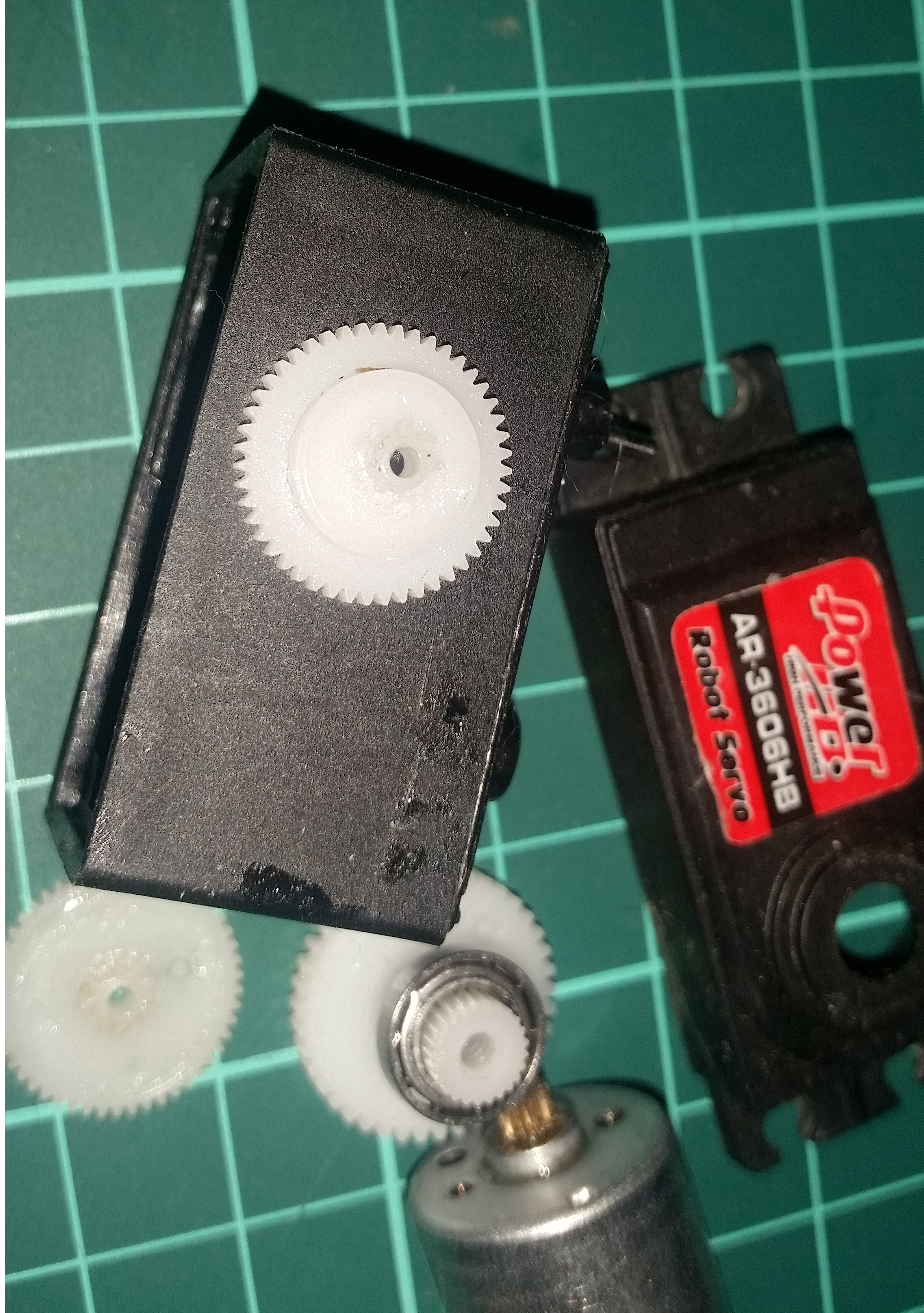
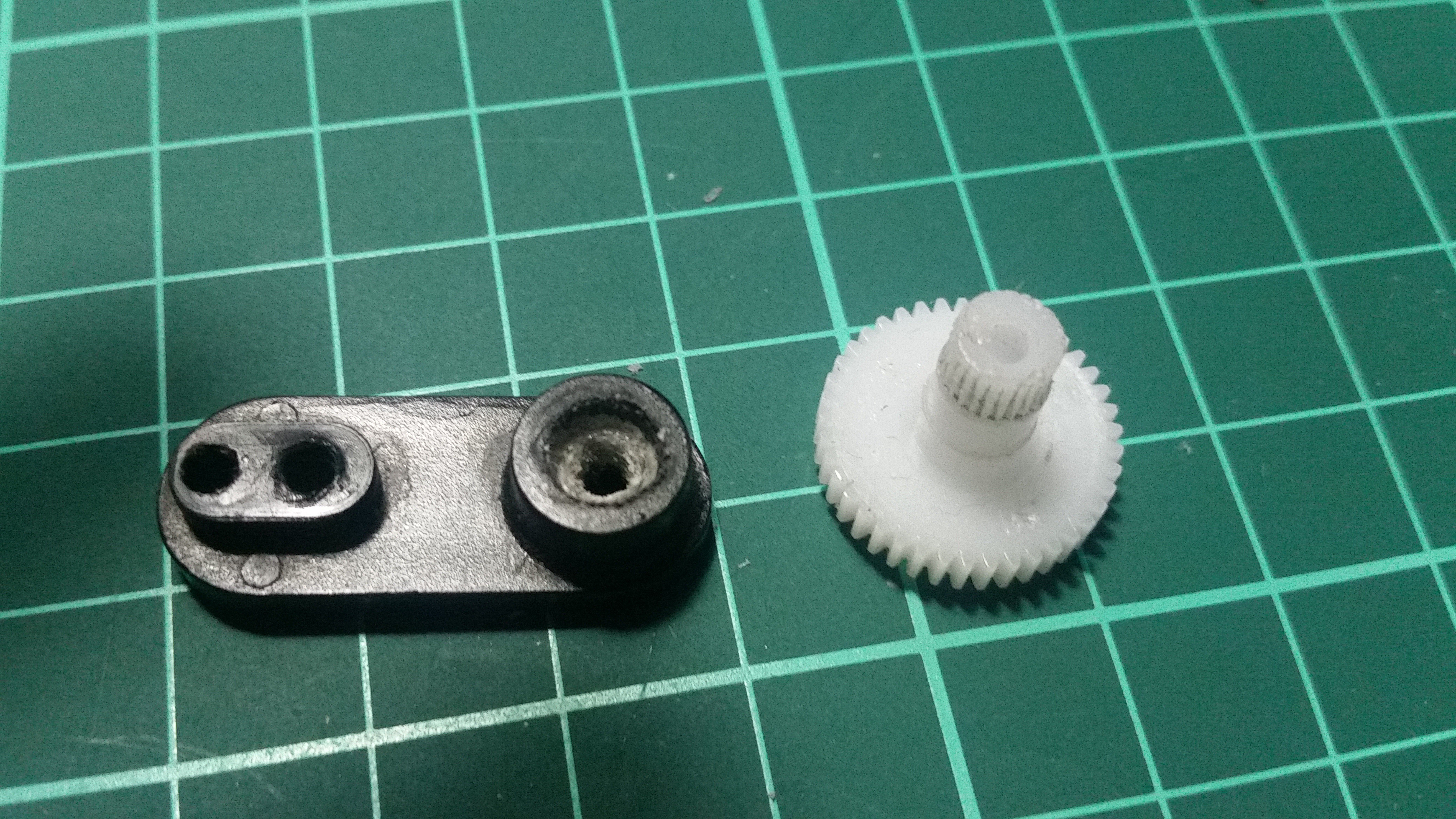
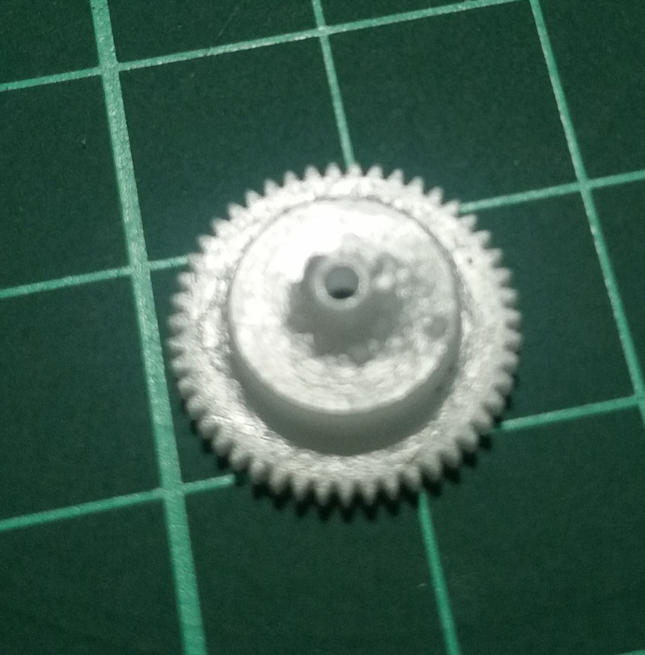
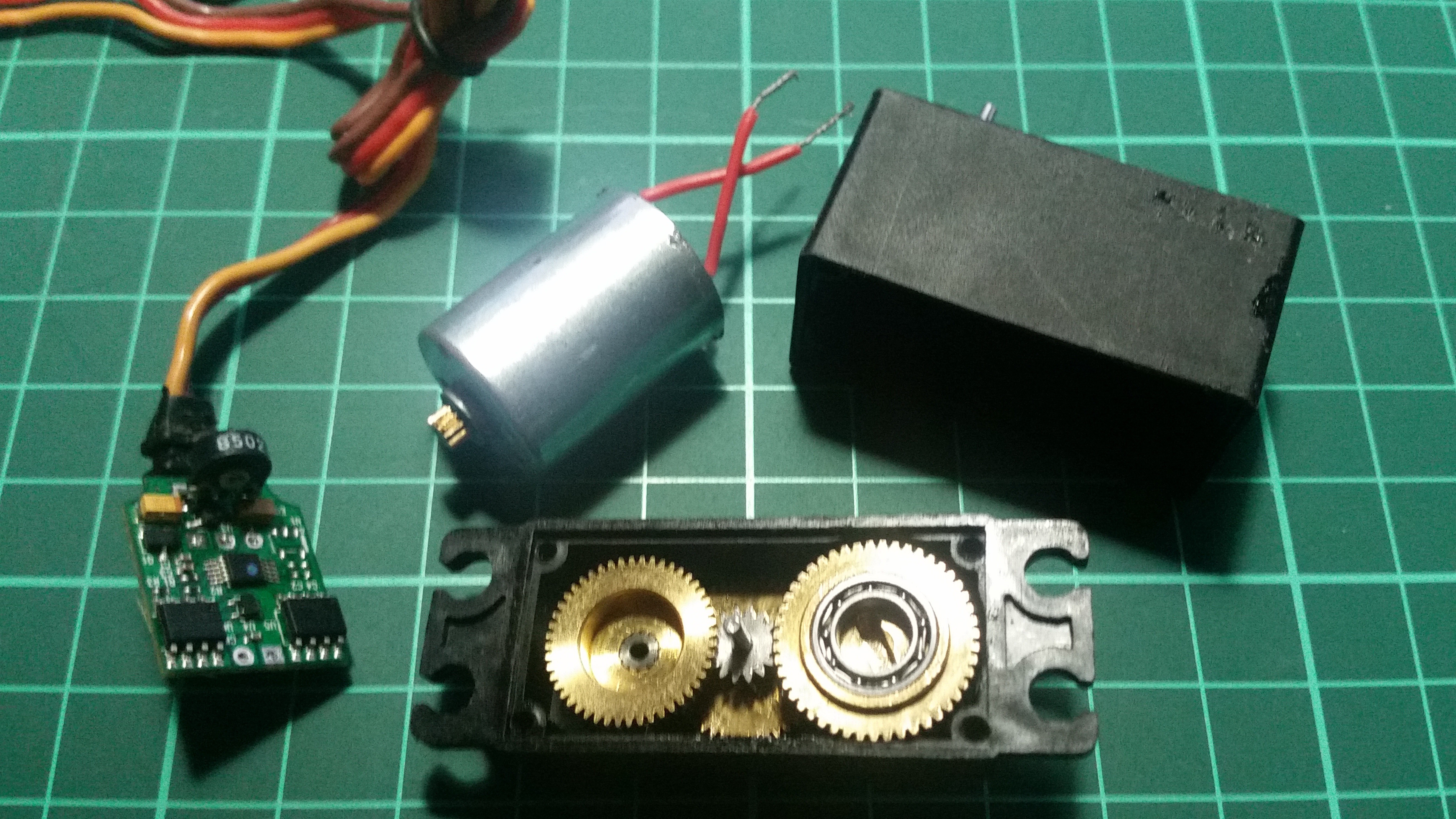
05/29/2016 at 19:56 • 0 commentsAt my first test, 6 kg servo successfully managed to turn the lock cylinder and opened the door. But after a couple turns, the servo destroyed itself. As you may notice, the servo I've choose for this project has plastic gears on it. I've found out that the plastic gears are not suitable for this kind of applications. Servo arm and it's attachment point were also damaged during the tests. This happened since there was no sensor threshold detection algorithm yet. Therefore I have to find a threshold detection algorithm before continue testing.
![]()
![]()
![]()
Modified New Servo
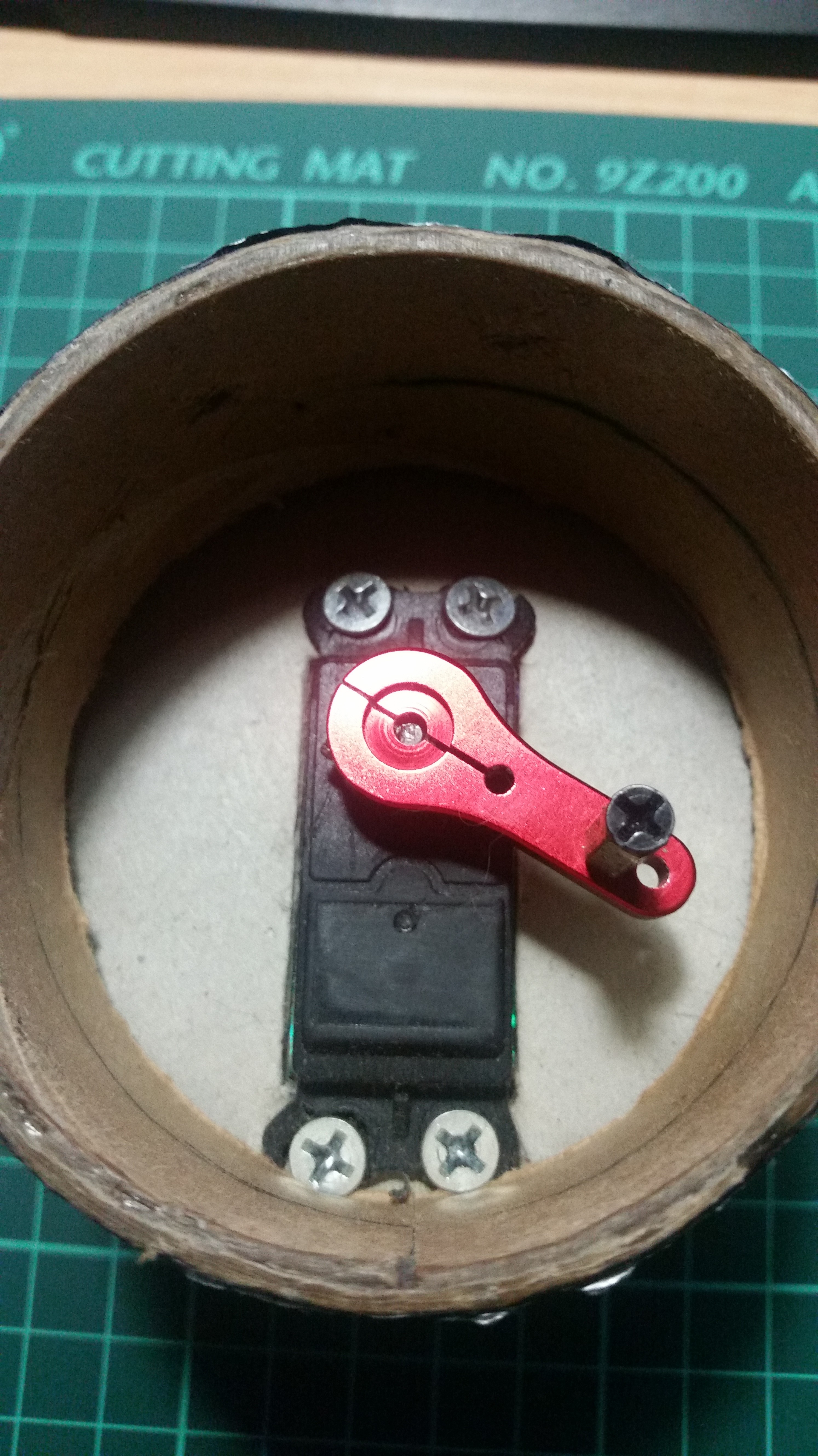
I found a metal geared servo in my small junk yard. I removed the internal electronics of the destroyed servo and mounted them to the metal geared servo shell. I also bought a metal servo arm which has side screws to mount it to the servo shaft.
![]()
![]()
![]()
-
Mounting the servo
05/29/2016 at 18:52 • 0 commentsI was not able to calculate the exact torque needed to turn the lock cylinder but I thought a 6 kg torque servo will be enough. To test the servo, I needed a way to attach the servo to the door and I started to think about the enclosure. At first, I thought I may use a 3D printer to build the enclosure but it was not going to be cheap, because I don't have an 3D printer.
Enclosure Material
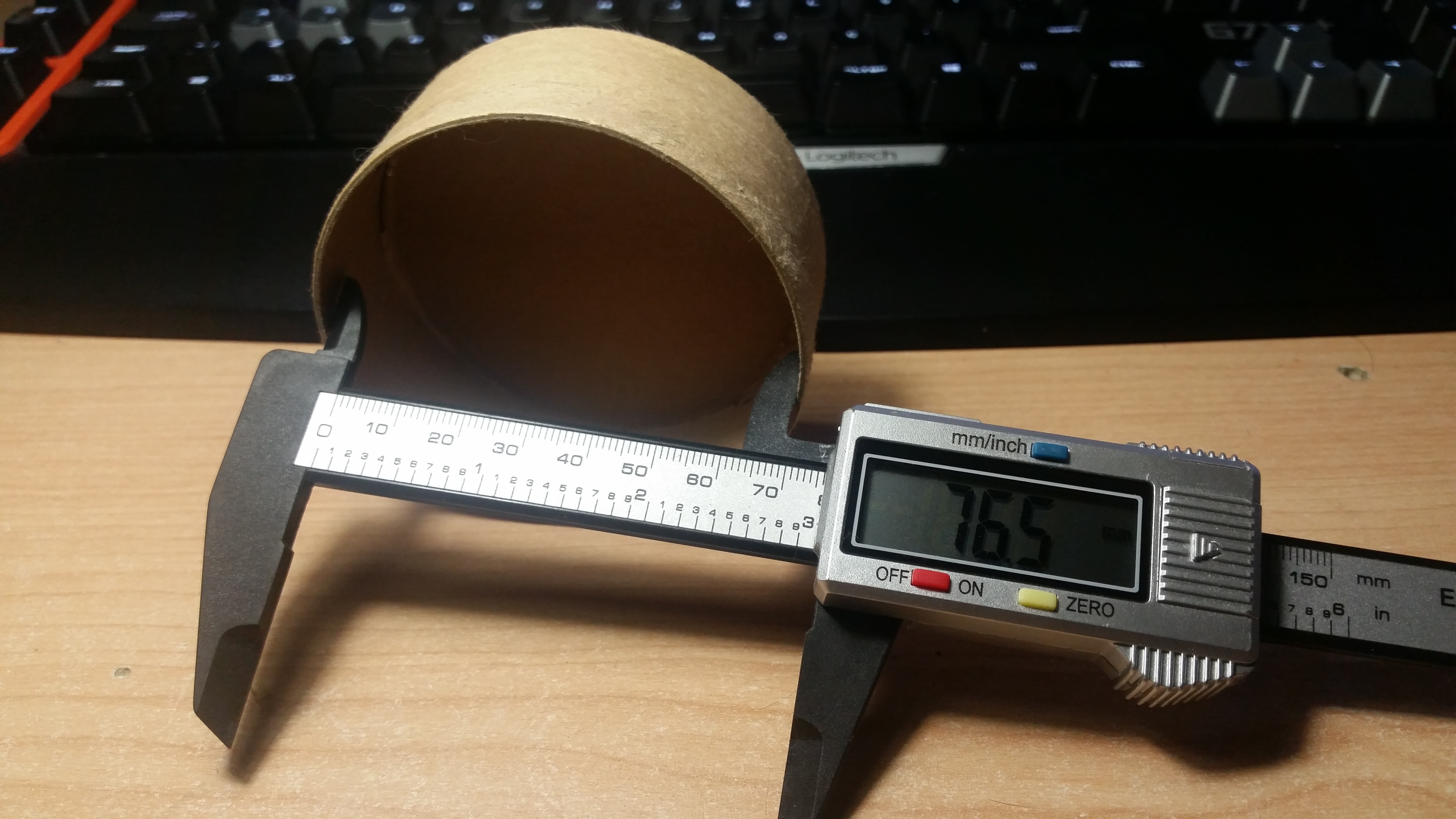
![]() I found these cylindrical cardboard boxes. They have used to be the boxes of t-shirts that i bought. With 800mm of diameter, it is the perfect material to work on.
I found these cylindrical cardboard boxes. They have used to be the boxes of t-shirts that i bought. With 800mm of diameter, it is the perfect material to work on.Servo Holder
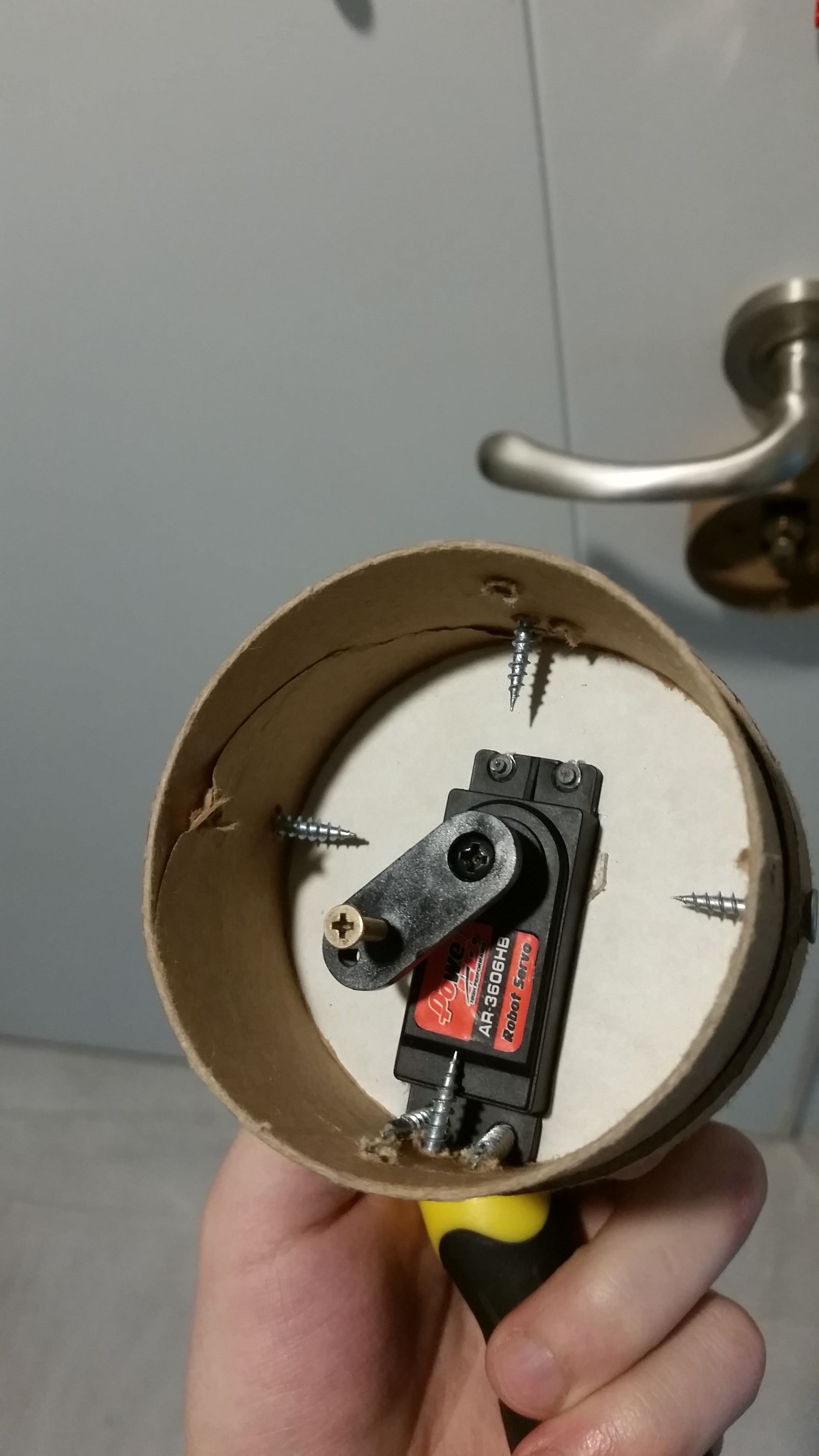
Cardboard boxes has removable caps so I did cut an rectangle and screwed the servo using its mount points. I can use existing screws to attach another cap to the door.
![]()
![]()
![]()
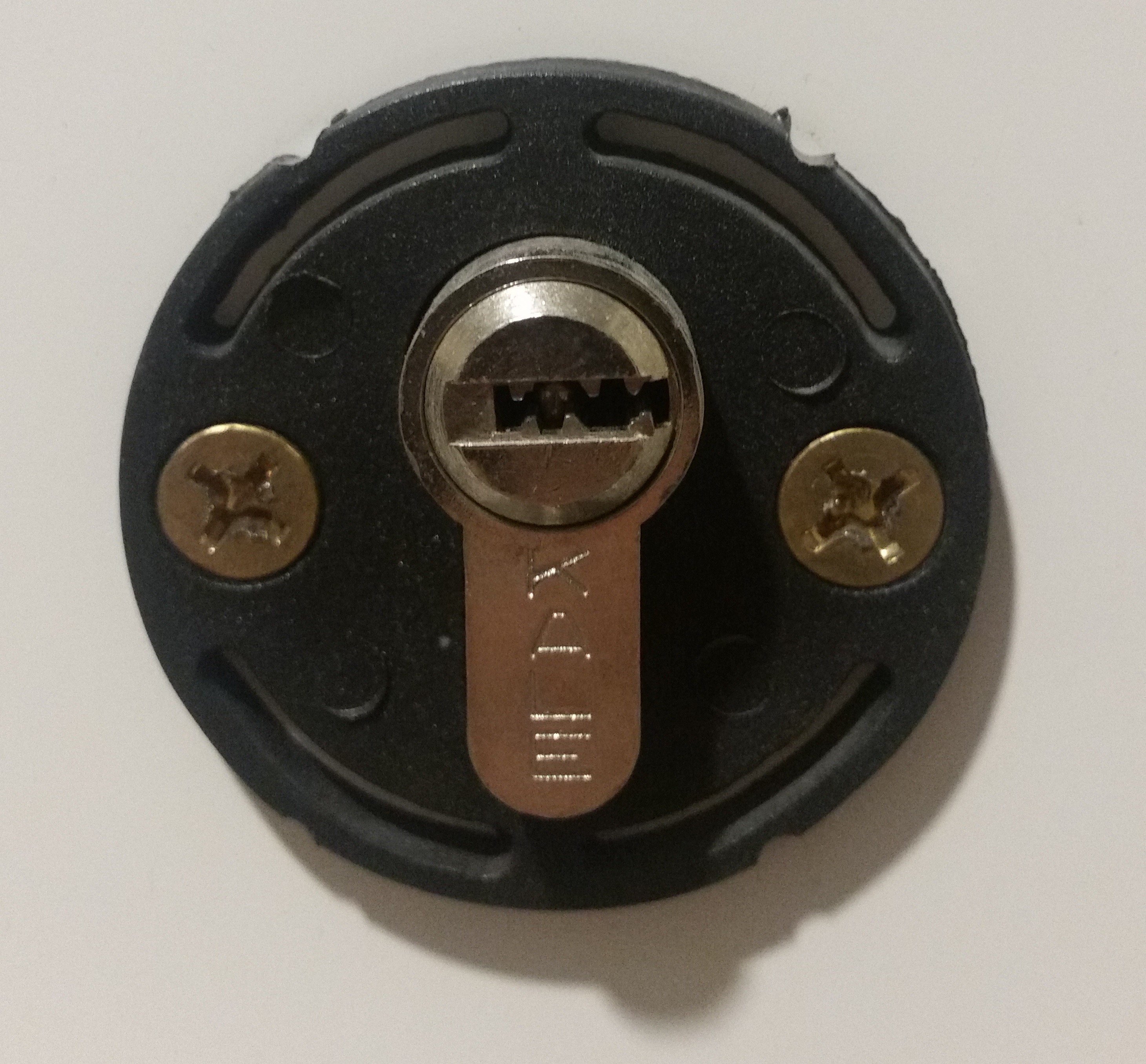
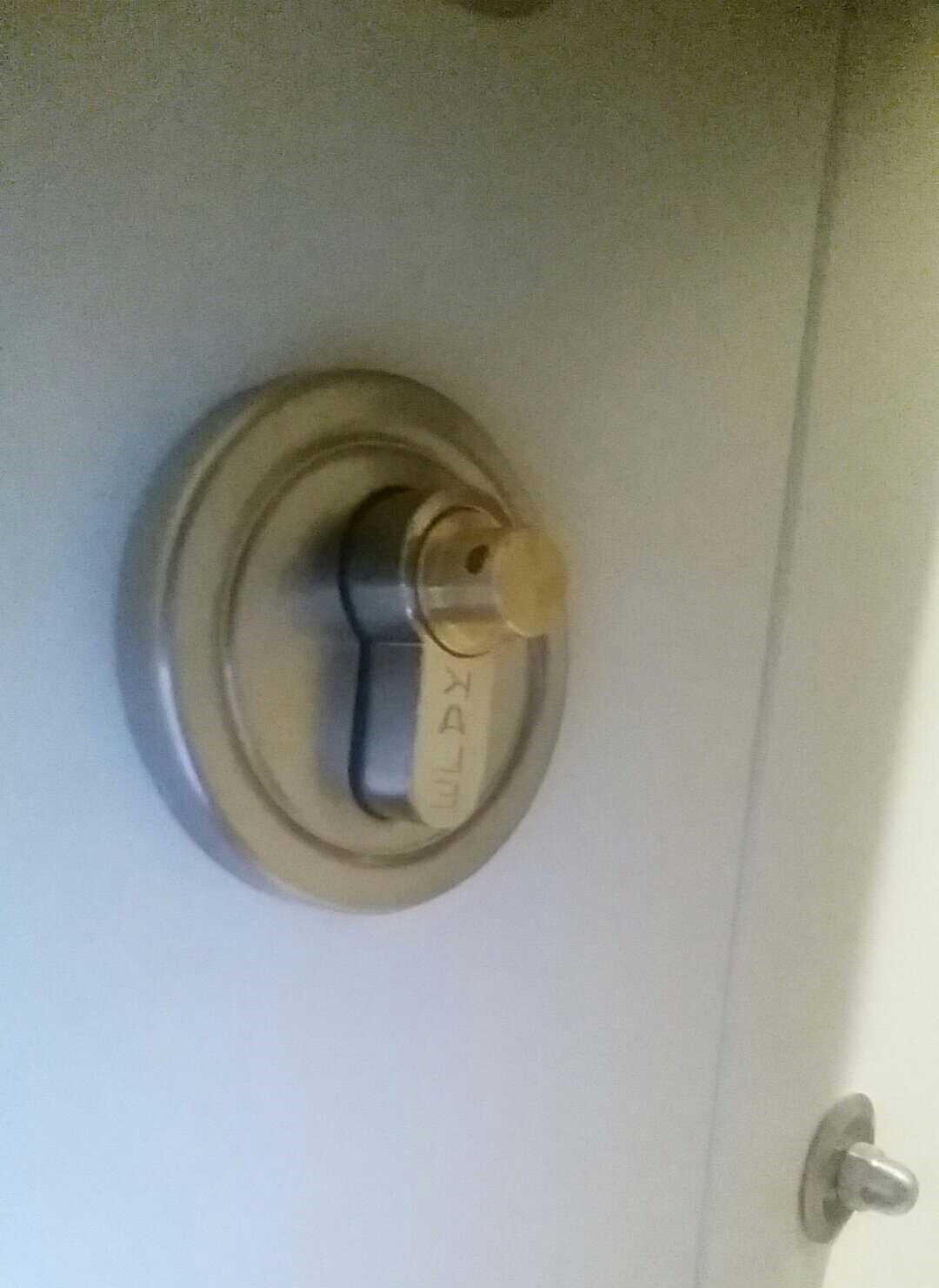
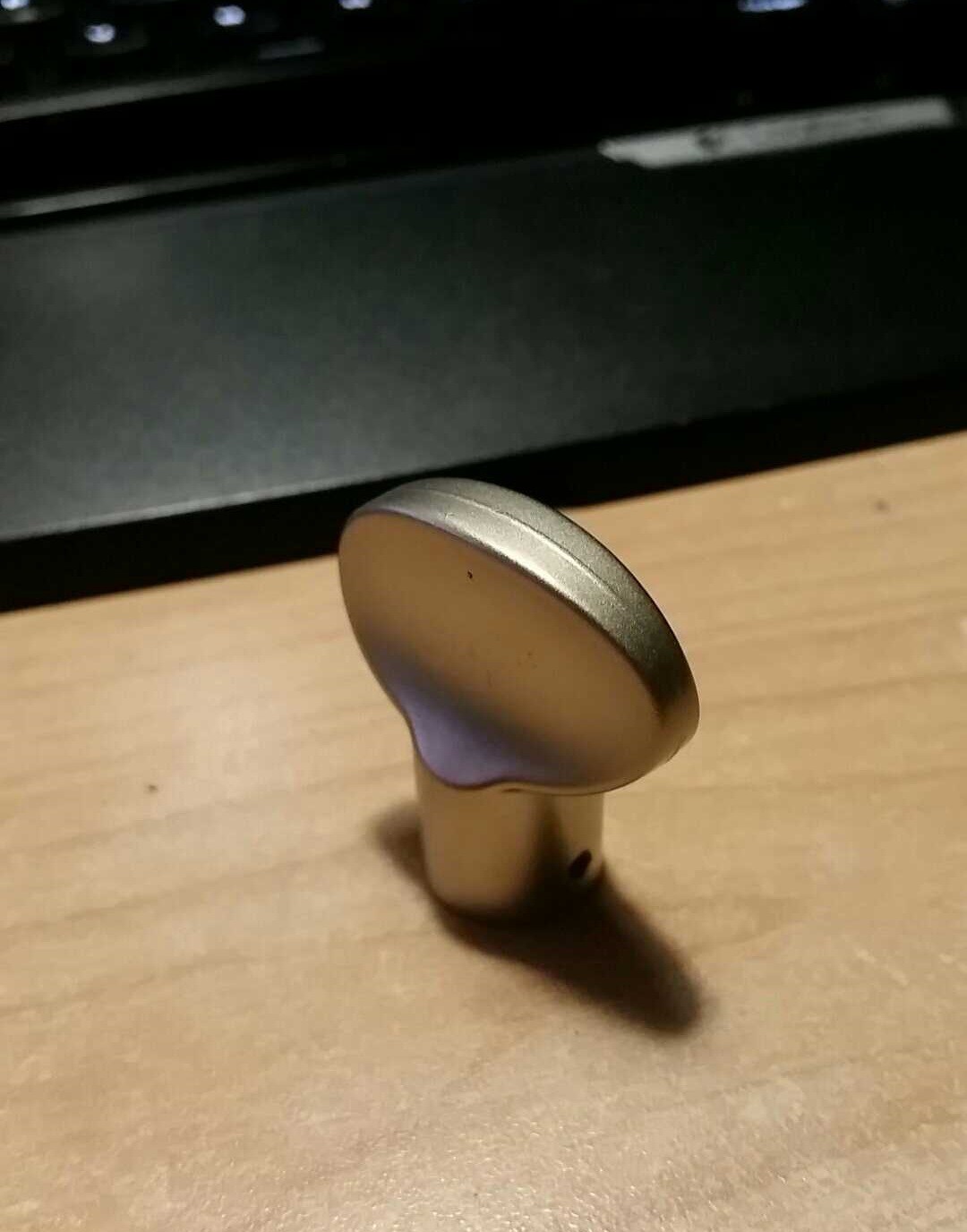
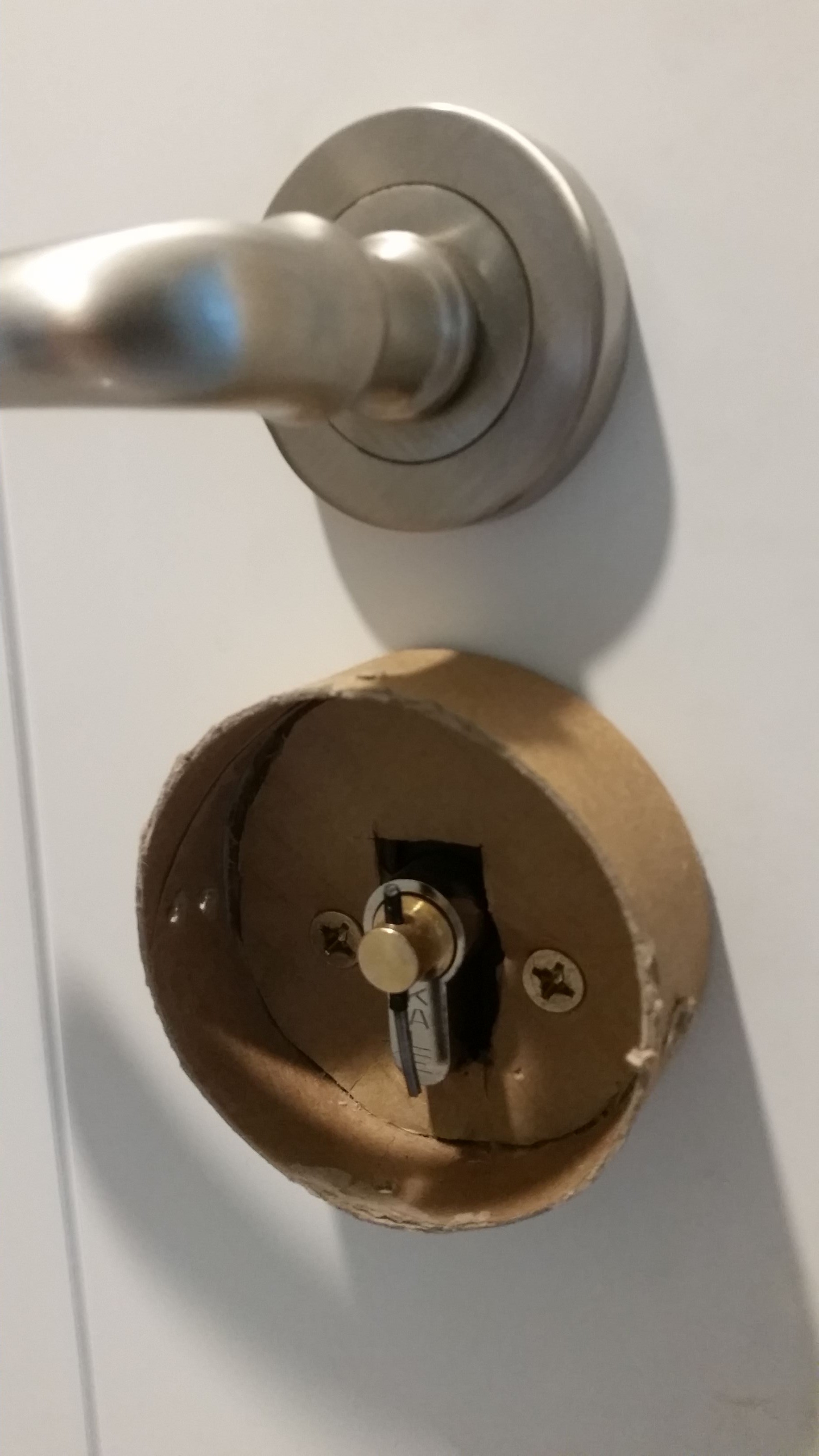
I removed the knob from the lock cylinder and used the hole on the cylinder to attach a longer pin. This long metal pin will be used to attach the servo arm to the lock cylinder.
![]()
![]()
![]()
-
Testing the current sensor
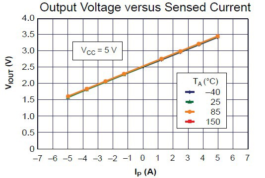
05/28/2016 at 21:45 • 0 commentsurrent sensor provides an analog output of 0-5v; it can measure both positive and negative current. Therefore, when there is no load, sensor outputs 2.5v.
![]()
Before I start to build the electronics and the enclosure, I have to check the sensitivity of the current sensor.
![]()
Arduino has 5v ADC but ESP8266 works with 3.3v. I could build a simple voltage divider to lower the sensor output voltage but instead of that I connected sensor output in reverse polarity. Because servo always draw positive current, sensor output will never reach 2.5v. So when the servo is drawing current, I read a lower voltage from the ADC.
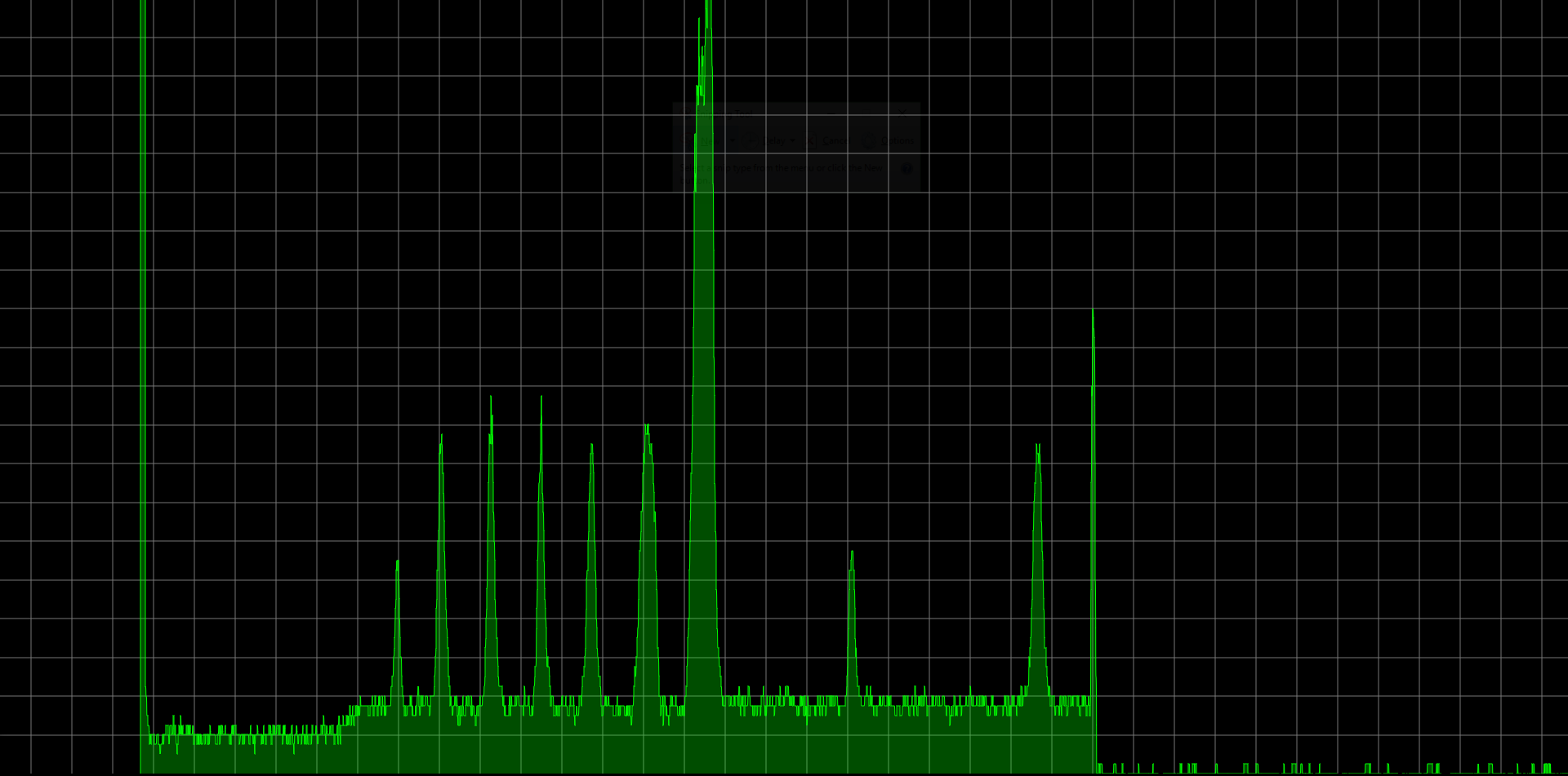
I wrote a simple sketch to output analog value using Web Socket connection. With an help of small JavaScript library, I managed to output analog value as graph.
![]()
Actually sensor is pretty accurate but there was too much noise on the analog input. It's impossible to determine a threshold point without using a smoothing algorithm.
const int numReadings = 10;
int readings[numReadings];
int readIndex = 0;
int total = 0;

int inputPin = A0;

int smoothValue() {
	total = total - readings[readIndex];
	readings[readIndex] = analogRead(inputPin);
	total = total + readings[readIndex];
	readIndex = readIndex + 1;
	if (readIndex >= numReadings) {
		readIndex = 0;
	}
	return total / numReadings;
}
You can find rest of the code at my GitHub repository.
 I found these