-
OS Upgrade and introduction of WiFi enabled device
08/30/2016 at 08:20 • 0 commentsThis log includes major upgrades included in the current system.
Till now we had been using an older OS incompatible with RPi 3 since the display could have only worked with that image. Additionally it caused the trouble where the onboard or external wifi dongles were not able to work with it.
Since Waveshare introduced the new RPi 3 compatible image, we tried to build the entire system ( dependencies ) again onto the new OS.
This is the OS that was used :
Raspbian Jessies waveshare 5" LCD (B) display - compatible image for RPi 3. ( Webpage | Image )
Later we installed/performed the following onto the Pi.1) OpenCV
2) pigpiod
3) All flask and python dependencies
4) Expanded Filesystem
5) Configured picamera
6) Configured crontab to start the required processes at system startup
7) Installed Chromium
After performing all these we were able to make a " Burn and Run " image of the device.
Now this image can be burnt onto any sdcard and inserted into the pi to be used for making the OWL device and we are ready to go.You can download the OIO/OWL device image here.
This image is not final and we will still be adding more functionalities to the device. A few exception handling issues are yet to be resolved.Issues resolved after this:
1) Reduced System boot up time.2) Wifi enabled
3) Lighter OpenCV (not all unessential dependencies were installed)
4) Overall increase in system performance
-
Testing the Machine Learning API
08/22/2016 at 06:19 • 0 commentsThe machine learning system on cloud was working well on the website theia.media.mit.edu - our goal is to integrate this into the device via API, so that whenever someone takes images they can choose to grade it by sending it on cloud. The natural limitation of this is that the user needs access to the internet, which may not be available in remote areas, and so we would eventually have to move the processing of images onto the raspberry PI itself. At the present moment, for a proof of concept we would use the cloud-based system.
This is written in python as a seperate module, with a function grade_request() that is callable, with the filename supplied as an argument. The API takes a multipart form, in which we send the file object (C-style, returned by open() in python) using the requests module. The API request requires a unique token which is generated by the website - this would help us identify the institution/device making the request.
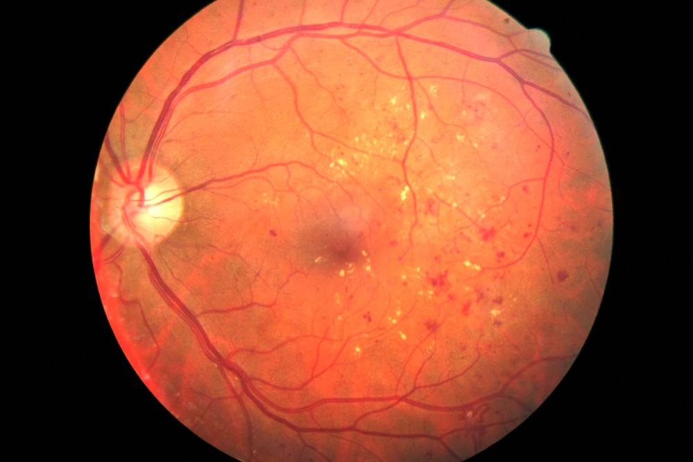
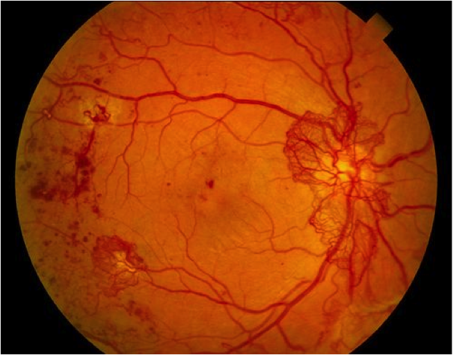
The server returns a 200 reponse, and a JSON object containing the grade as a float (from 0.0 to 4.0). To test it out, the following table surveys a few test images and their responses from the server:
Image Grade ![]()
2.08 ![]()
0.09 ![]()
0.13 ![]()
0.33 ![]()
0.08 ![]()
2.27 ![]()
3.08 ![]()
2.43 As can be seen, even the first image, which had a lot of noise (i.e. non-retina artifacts like the lens holders and other parts in our device which had not been computationally removed) gave a result which matched fairly well with what we would expect. The algorithm was robust enough to not be confused by the whitish streaks as well as the black dots (artifacts - usually dust on the camera or lenses) in the 4th image, correctly labelling it within the healthy bracket (less than 1.0).
These tests worked quite well on high-quality images from fundus imaging devices in the clinic. We would like to evaluate the performance of this system on images taken by our device. For this we need to convert our images into a format which is similar to what the clinical standard devices would output - which would start by understanding the limitations in our device's imaging capabilities. The fundamental differences between OWL images and fundus images are:
- The glare spots at the center - these would be removed by the computational inpainting method described earlier.
- Our device's images are limited to 30 degree field of view (FOV) - which need not be central. This is not a major limitation as this FOV gives enough information for a nonspecific retinal examination.
- Our images would have radial distortion due to the 20D lens and the M12 camera lens of the raspberry PI. This would result in slightly different edge distortions compared to a traditional fundus imaging device. To a human examiner, this would make little difference - but to the machine learning algorithm, this may have a non-negligible effect which we would have to investigate.
Point (1) would have the greatest effect on the DR score - since the white spots may be confused by the algorithm to be due to DR. The following table shows the scoring at different stages of processing:
Image Process performed Grade ![]()
None (raw image) 0.15 ![]()
Extracted the fundus from the background 0.12 ![]()
Removed the glare from the image 0.16 Interestingly, there was very little variation between the three images as far as scoring by the algorithm was concerned. However, we would need to conduct a large study on patients and healthy volunteers comparing images from our device and from clinical standard devices to really quantify how closely in agreement the DR grading is. However, for the purposes of a first stage screening device, the automation system broadly classifies images quite well.
-
Integrating Machine Learning and Automation
08/22/2016 at 05:03 • 0 commentsAt this point, we're getting great images from our device and multiple retina specialists agree that they're able to see the features they need to make a diagnosis. But clinical experts may not always be available to give their opinion for the massive number of patients during a field testing or a mass screening program. We want our device to have automated algorithms built-in which would allow the image to be "graded" by severity of the condition (Diabetic retinopathy).
Our starting point for the best solutions to this was to explore the solutions posted by winners of the 2015 Kaggle competition on Diabetic retinopathy. The winners made use of Convolutional Neural Networks, which are giving fantastic results in image detection problems.
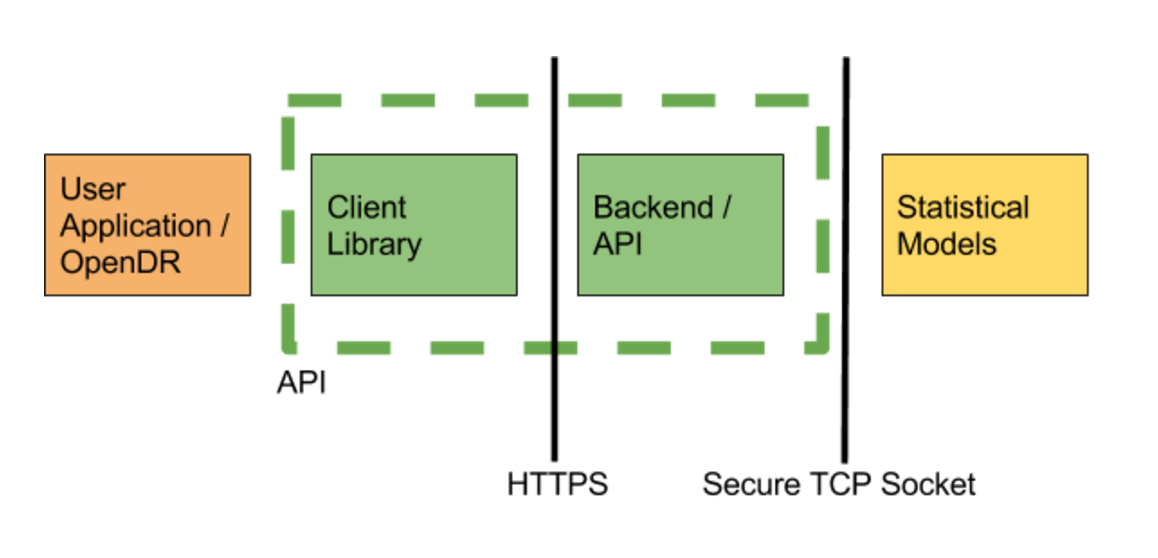
We implemented a version of some of the winning networks in the Kaggle challenge in Torch, and trained them using rack-based training machine running two Nvidia Titan X GPUs (24 GB total VRAM), 64GB of RAM, and 24 core CPU (similar to those available from Amazon Web Services). Training took about 2 days. After training the network we converted the model to run on both a CPU or GPU based machines. Running the service requires less substantial computing resources, our service currently runs off a desktop machine with 16GB or RAM, 8 cores, and a Nvidia GTX 760 graphics card (2 GB VRAM) in order to comfortably handle 12 image requests/second. For context, if everyone in the world was scanned once a year (7 billion), then we would only need 20 prediction machines, or about $20k (+supporting infrastructure). Finally, to complete the service, we built an API to serve image requests. The service consists of the predictor, written in torch, and a web server, written using the python flask framework. The server receives images, verifies files and sends a pointer to the image data over a socket using TCP to the predictor, which responds with the predicted grade. This configuration allows us to run predictors and the web server on different machines for scale, but currently our service runs off a single desktop. In the future, our CPU based models can run on embedded ARM hardware such as a Raspberry Pi.
![]() In order to interact with the web service, we created a client library in javascript and python. A user makes a profile and is given an API key from our web server. Through this, the processed jpg image is sent as a multipart form. The server processes the image and returns a json object. The grade is returned as a float between 0 and 4, with the following interpretation:
In order to interact with the web service, we created a client library in javascript and python. A user makes a profile and is given an API key from our web server. Through this, the processed jpg image is sent as a multipart form. The server processes the image and returns a json object. The grade is returned as a float between 0 and 4, with the following interpretation:0 - No Diabetic Retinopathy (DR)
1 - Mild
2 - Moderate
3 - Severe
4 - Proliferative DR
The OWL client receives this data and converts it into a simple UI object which is easy to interpret by a field worker or layman.
A live demo of the grading interface lives at https://theia.media.mit.edu/ and the code is being continuously updated at https://github.com/OpenEye-Dev/theiaDR. The algorithm was trained on several thousands of images sourced from partner hospitals globally, including the LV Prasad Eye Institute, Hyderabad, India.
-
A better and faster way to remove glare
08/17/2016 at 05:14 • 0 commentsThe earlier method of glare removal was too complicated and the processing was taking too much time. In addition, the use of SURF algorithms had some disadvantages:
- They are not free/open algorithms and require extra licenses
- They distort the images through an affine transform
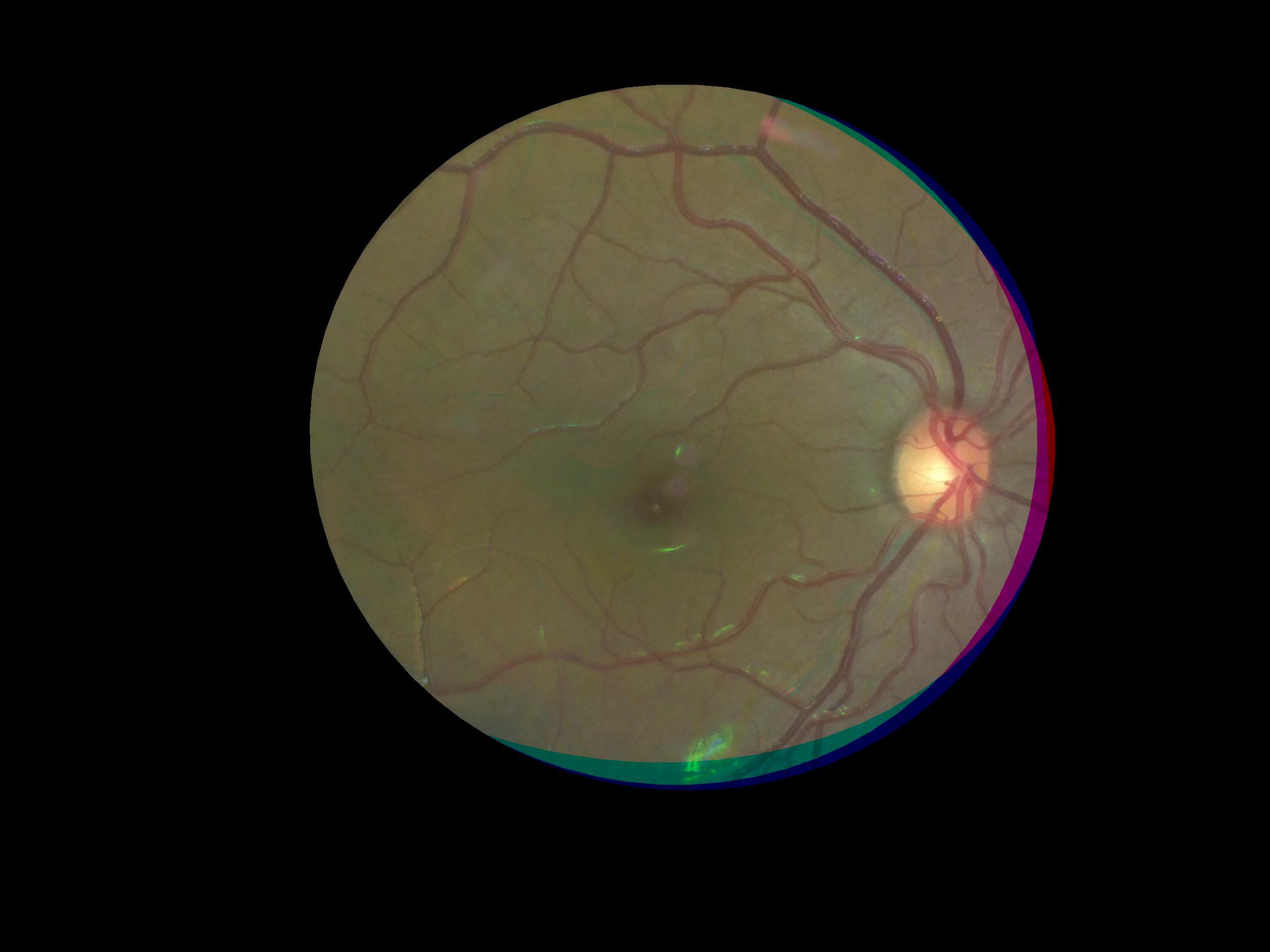
- R/G/B channels are distorted differently and hence the corners of the images (where lens distortion is higher) showed channel mismatches, like the image we shared earlier (shown below).
![]()
A little "out of the box" thinking made us realize the following about the spots:
- They're always in the same location on the image
- They would usually cover the macula or the central retina (a small portion of an otherwise much larger image of the retina)
- We can and will always take multiple images from the same patient
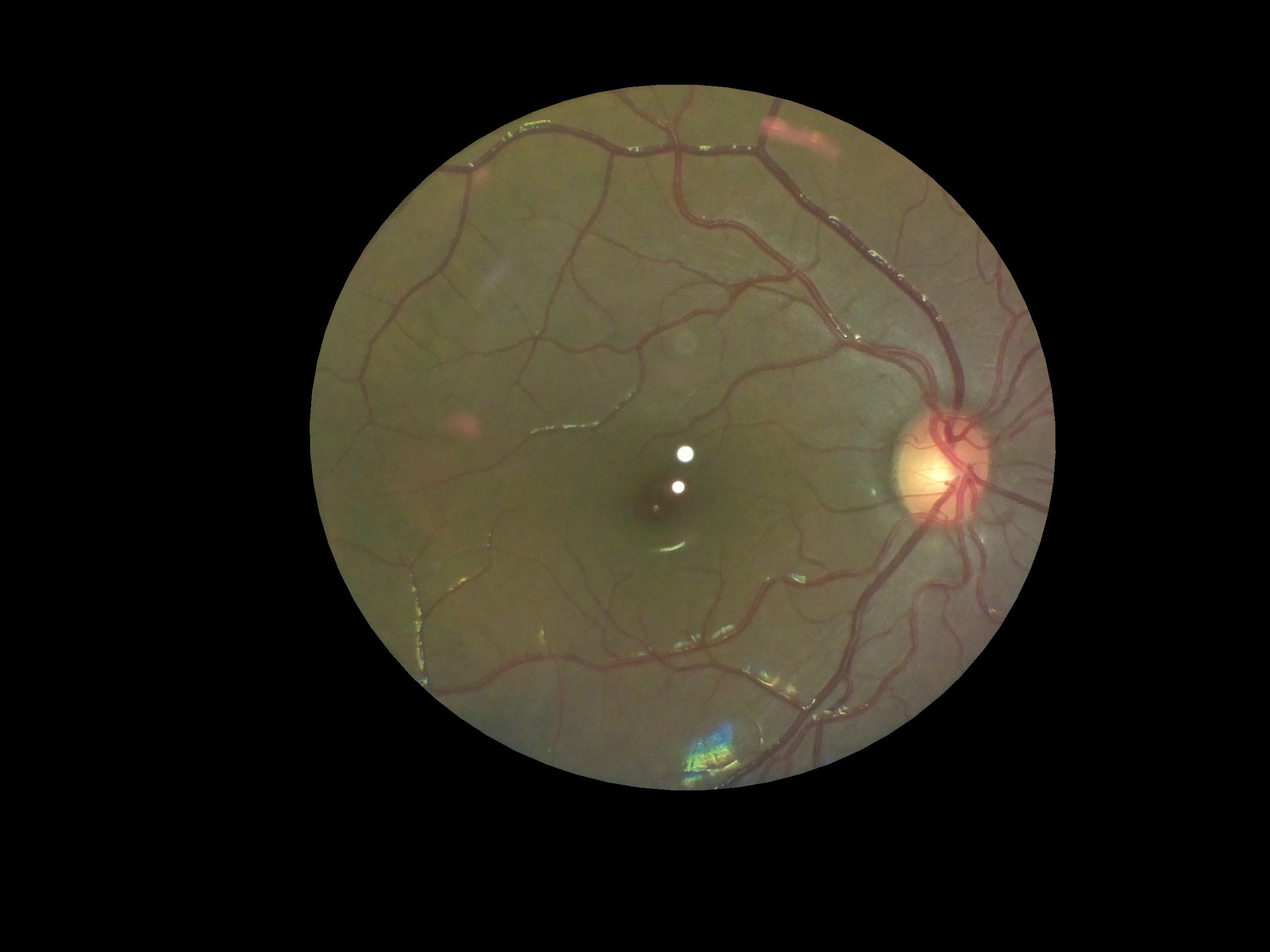
We also wanted the processing algorithm to be extremely fast. Hence we decided to use opencv inpainting. This method allows us to segment parts of an image out and interpolate the "hole" from the surrounding parts of the image to get a clear image. Also, because we know that the bright spots only lie in the center of the image, we could only perform these image processing operations on a small central "region of interest" of the image, drastically reducing the number of pixels that need to be processed. The result is shown below:
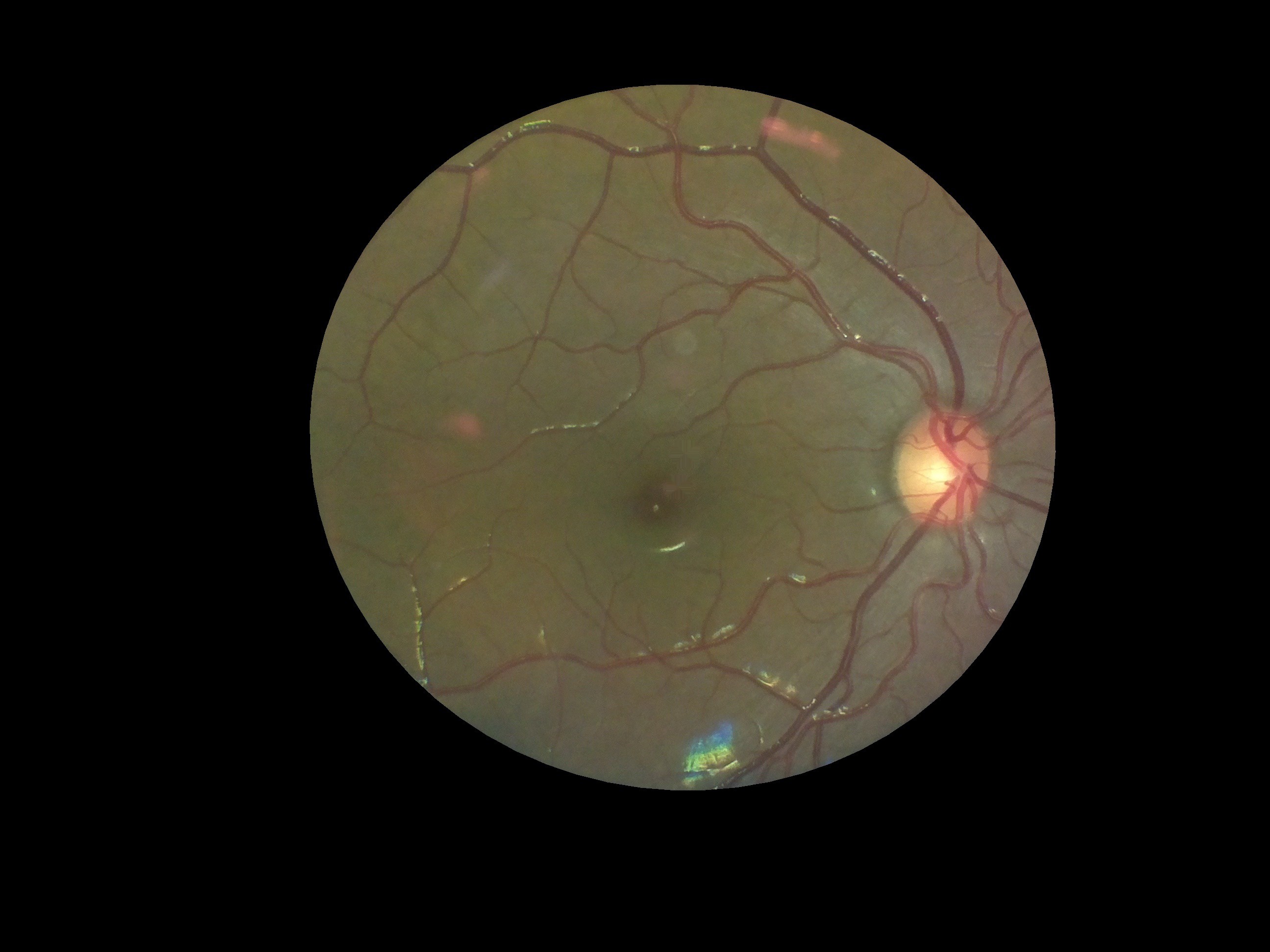
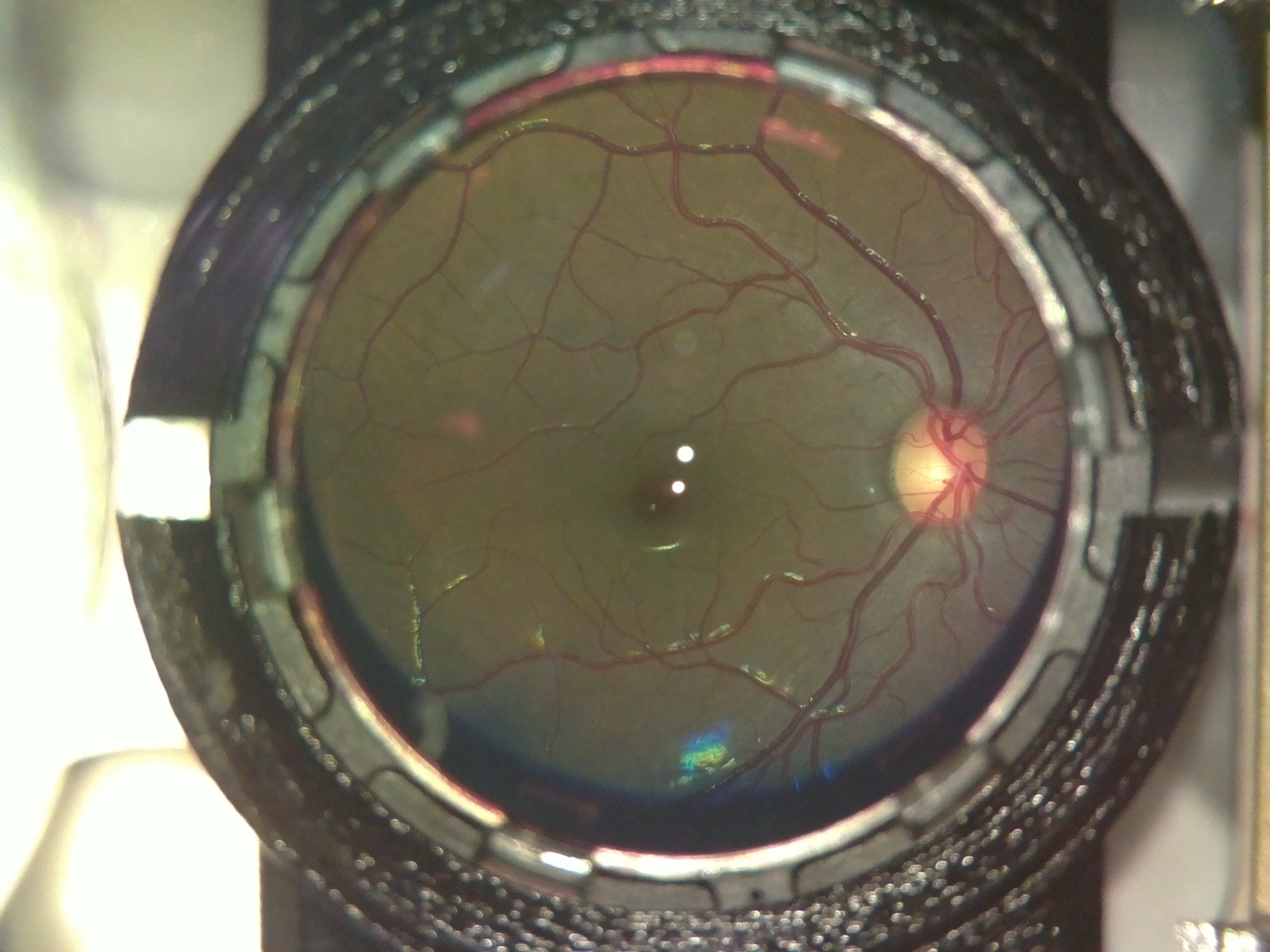
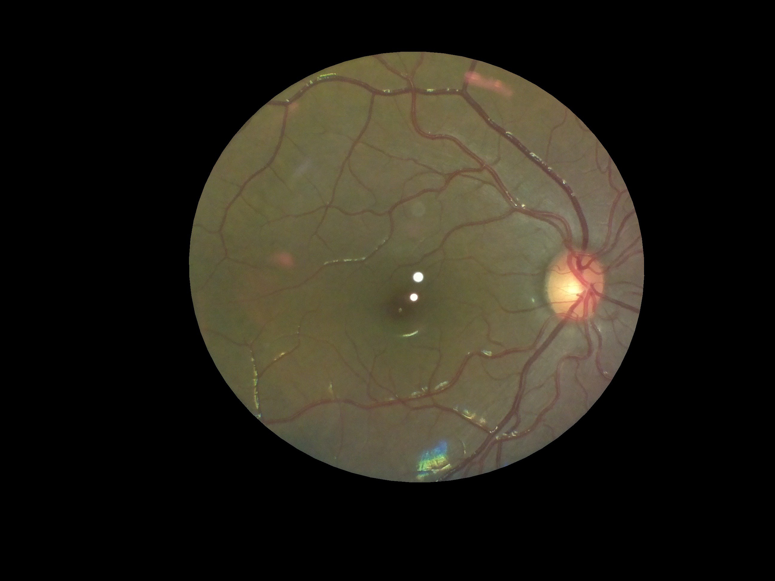
Here's our input image, after processing to extract only the "fundus" section:
![]()
And here's the same image after inpainting the glare spots (and playing around with an optimum dilation kernel, which was found to be 25x25px):
![]()
It does a great job! The code (all in python) is available here on our github repo. As can be observed, for the purposes of an examination by a clinician, it's perfect. Also, it's all in python and can be easily integrated with the rest of our code. It also uses all opencv core functions, which are covered by the BSD license.
The code took 8ms to process this image on a macbook pro (13" 2015 model) and 71ms on the raspberry PI model 3B... not fast enough for live processing, but definitely fast enough for processing post-capture!
-
Cost cutting
08/12/2016 at 11:20 • 0 commentsTo make it more scalable we are finding ways to cut down the cost of the components. Most of the components can't be changed such as camera, Rpi and lens (already using a plastic lens instead of glass lens) this left us with the mirrors.
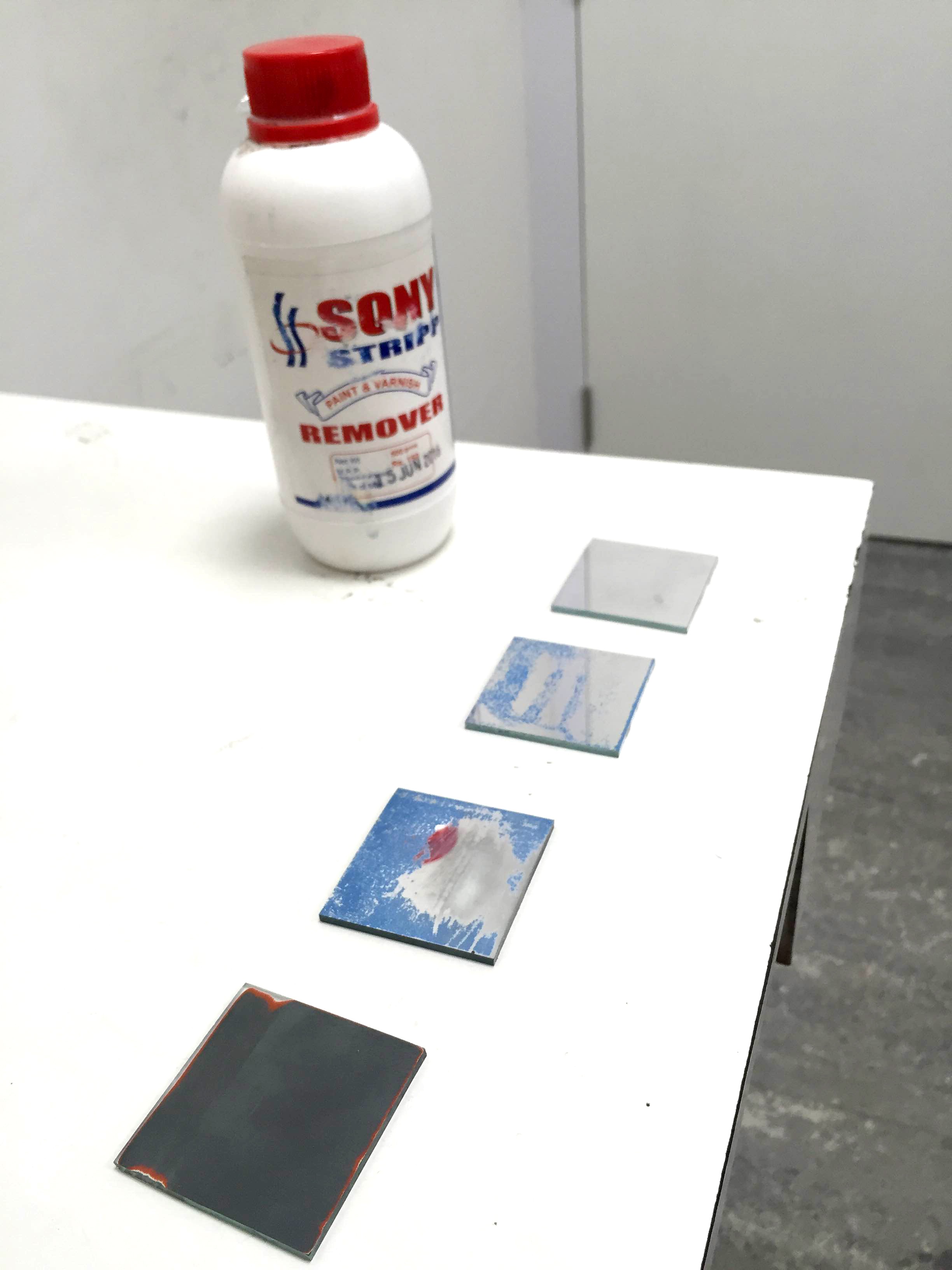
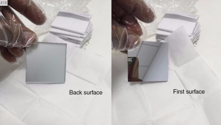
The present mirrors cost us $42 each that are from Edmund optics and we have two mirrors which is a lot. These mirrors are front end mirrors with first surface reflection which helps get optically perfect reflections and prevents getting ghost images. So we thought of converting a regular mirror into a first surface mirror. For doing that we should remove the protective layer at the back side of the mirror. So we used a paint stripper to remove the paint from the normal mirror and cleaned them to get a perfect clear glass.
But the paint removal process removed the reflective aluminium coating which reduced the reflectivity thus striking off the idea.
We searched with many local vendors for those mirrors and we found a provider for single surface front end mirrors form opticsindia which are locally manufactured. This is costing us $6 each. This cuts down the cost to a larger extent.
-
Background and glare spots removed
07/12/2016 at 11:30 • 0 commentsSo now that we've got excellent results from our field tests and doctors were reasonably happy with the device, OWL's first prototype was all ready to go. But before pronouncing it complete, there was one task left: removing glare spots and extracting the fundus from the background.
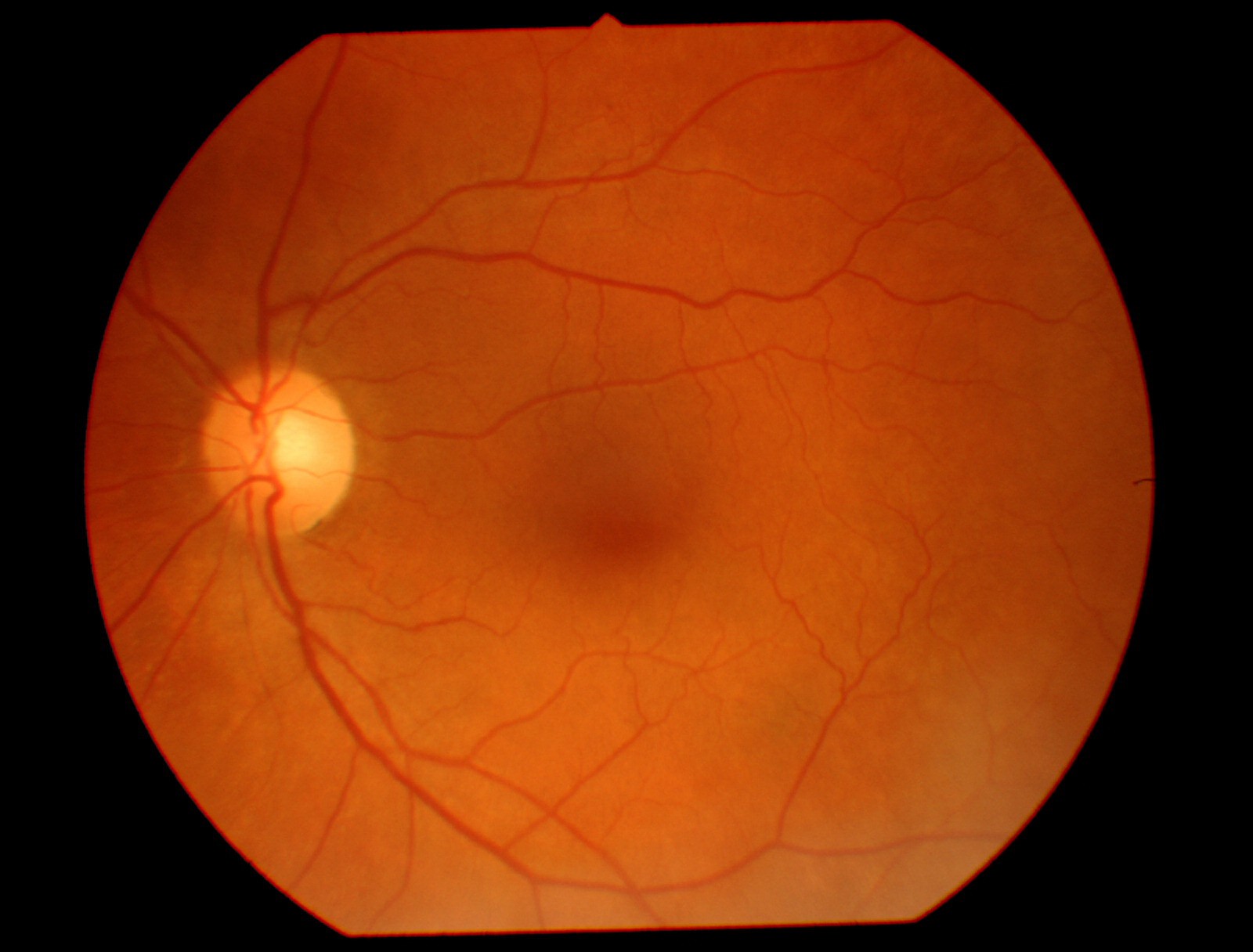
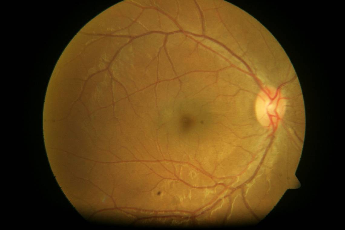
This is what a regular fundus camera gives:
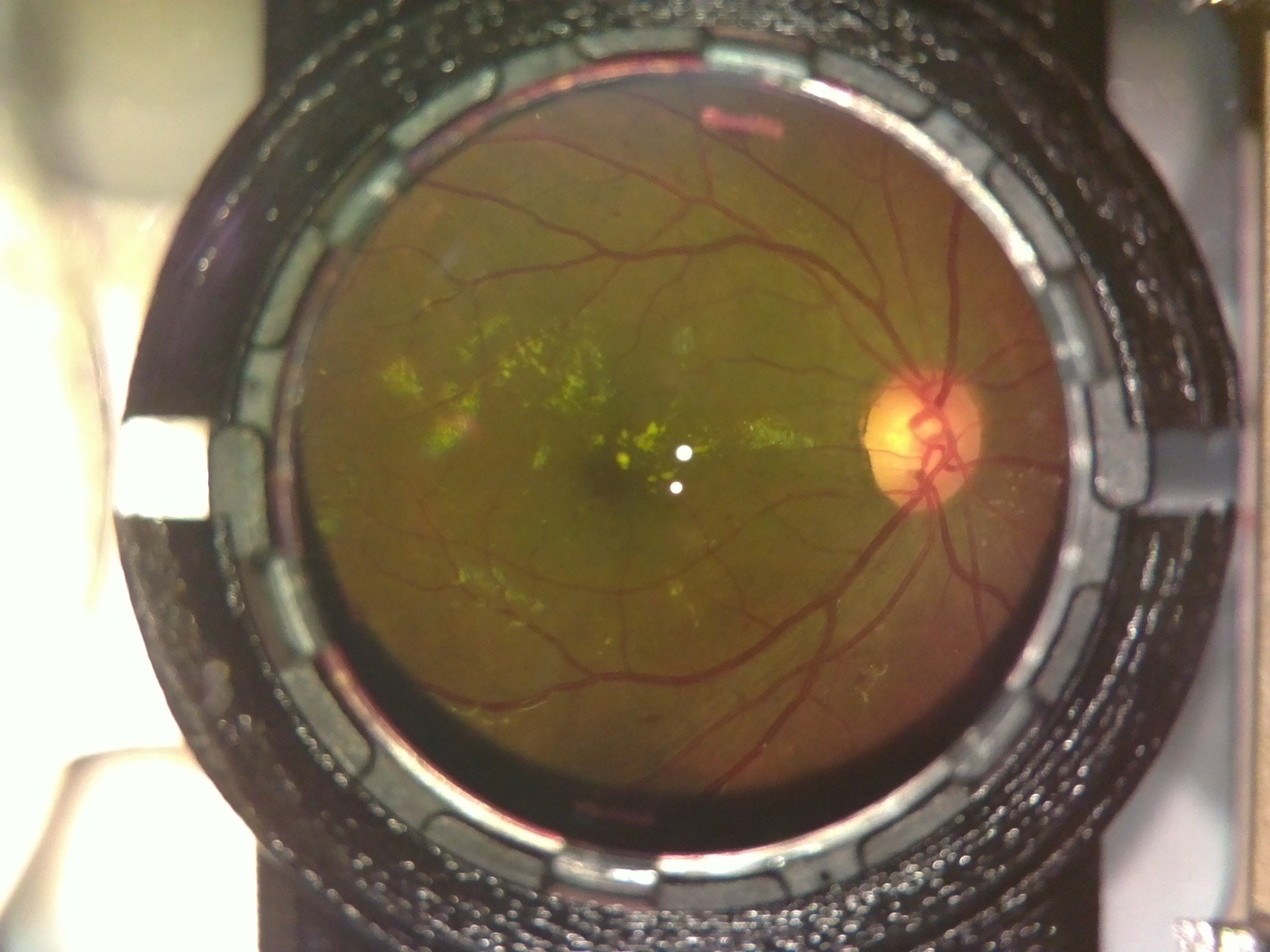
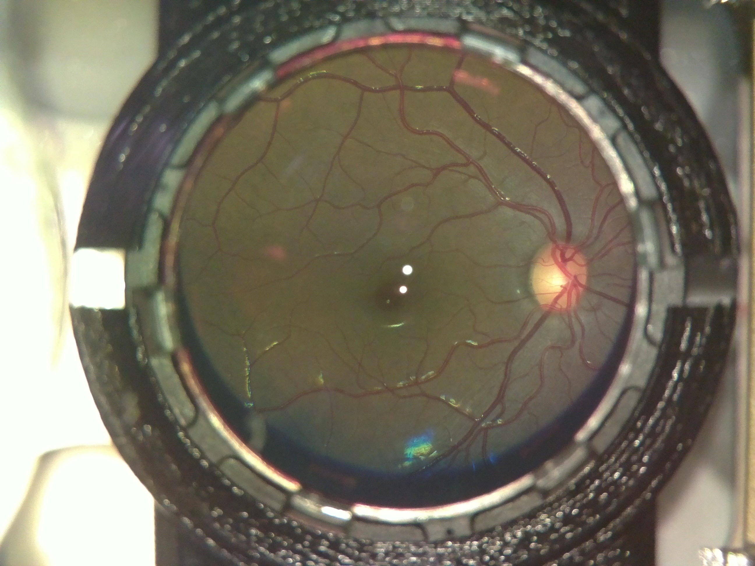
Here is what an OWL image looked like:
The extra elements in the background are the lens holder and casing of the device. Also the 2 bright spots in the center are due to glare from the led used for illumination. The colour difference is insignificant; the fundus camera uses a colour filter, while we don't.
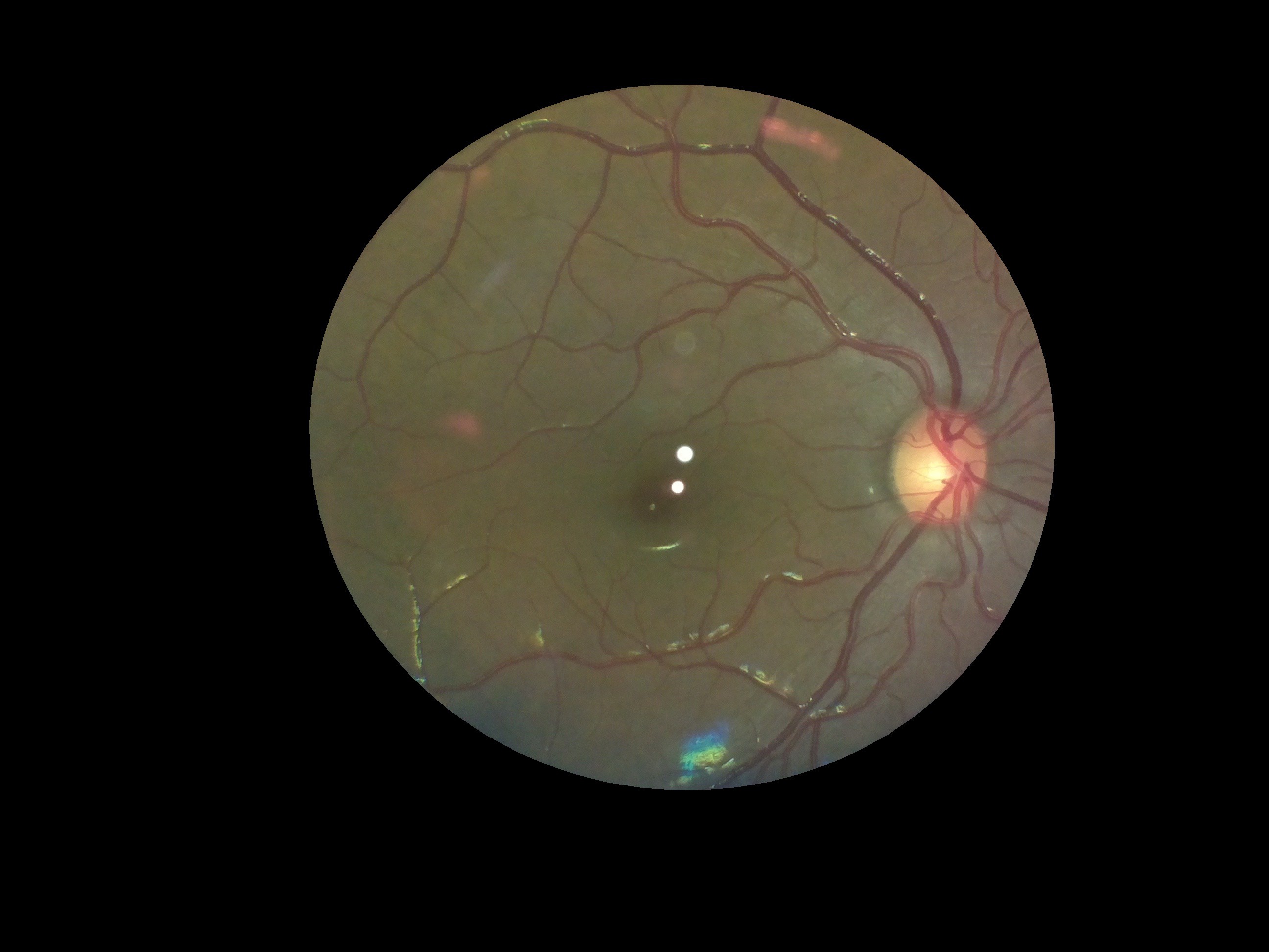
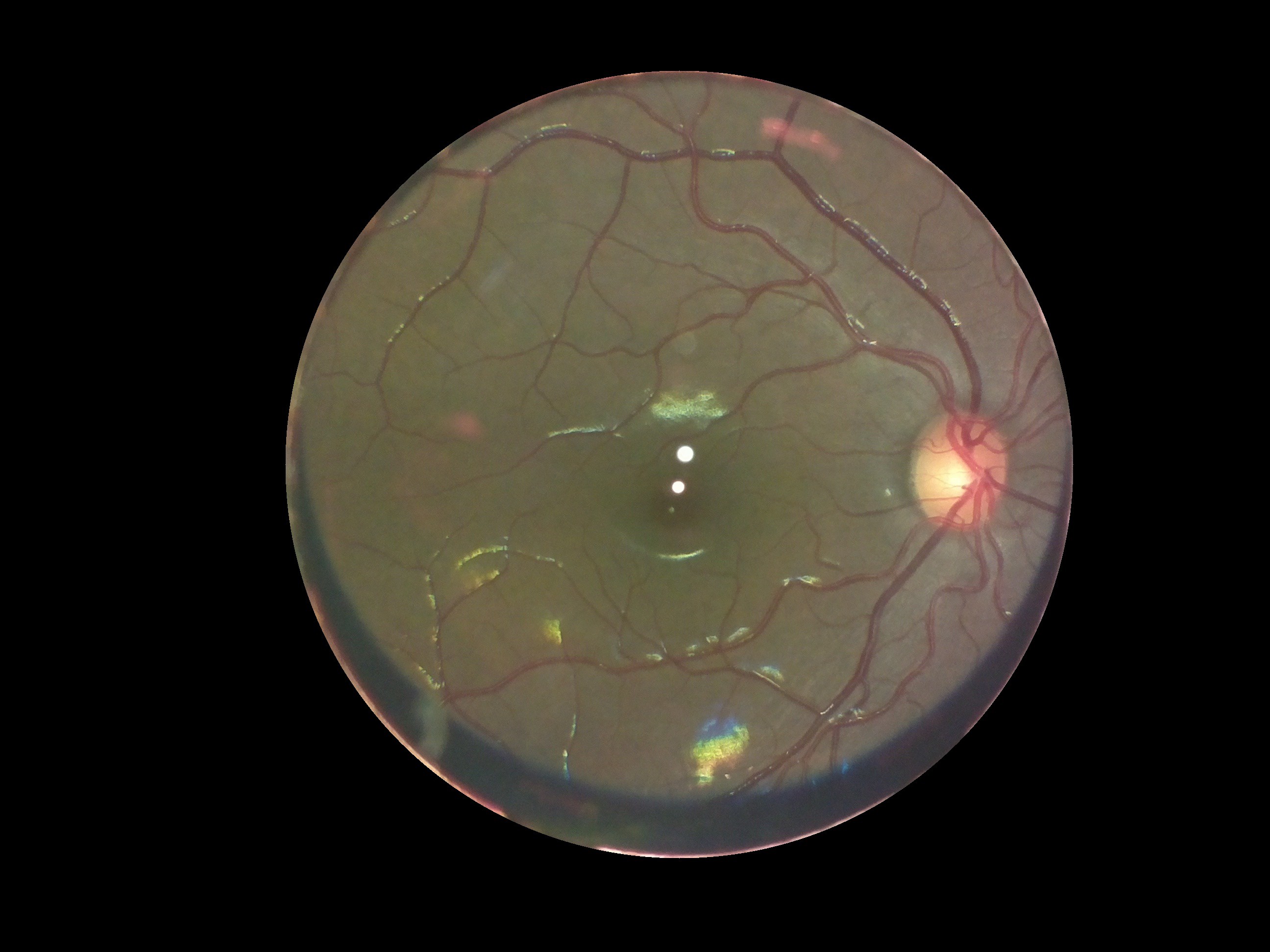
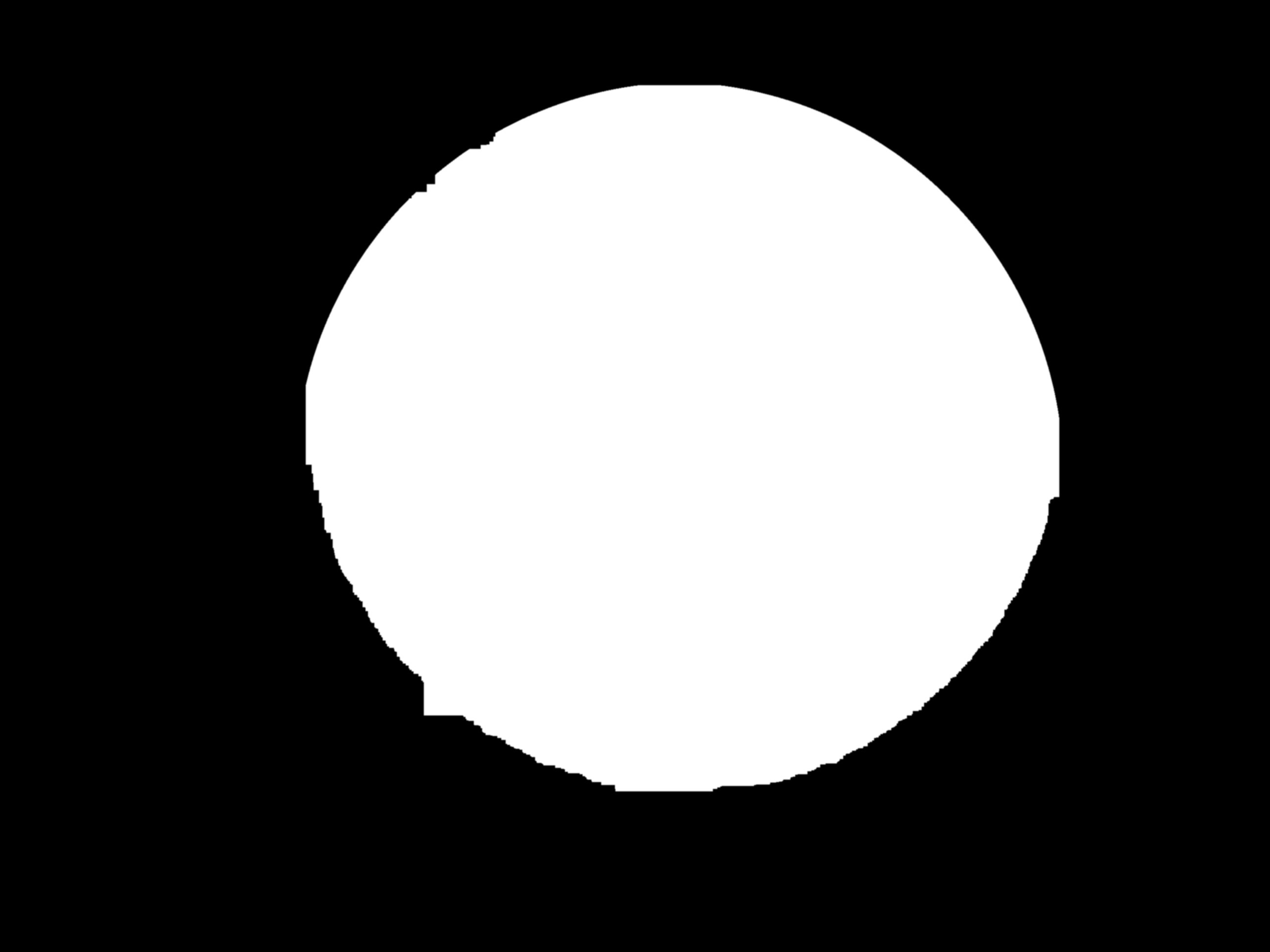
To remove the background, we first used the houghcircles function in opencv to fit a circle to the area inside the lens holder. Then we used the circle to make a mask and cropped out that area. The mask we used for cropping, would be the same for all images, since the camera and lens mount are fixed. So we saved the mask as a separate file, to use in other images as well. This we thought could help reduce the processing required, compared to using houghcircles in each image.
Then to remove the black regions inside that area, we thresholded the image.The mask as expected was jagged and had sharp edges.![]()
So we tried eroding,dilating and blurring it to make the edges smooth and finally fit an ellipse to it, to generate the final mask. Then we used the final mask to extract the fundus from the initial image.![]()
![]()
The code used for this can be found here :https://github.com/mahatipotharaju/Image-Stitching-/tree/Opencv-Code
After extracting the fundus, the next task was to remove the spots. For this we took multiple images of the same fundus, but such that the spots fall at a different part of the object in each image. This way, what was covered by the spots in one image would be visible in another one. Then we did a feature mapping of these images using FAST and superimposed the images. The tutorial we followed can be found here: http://in.mathworks.com/help/vision/examples/video-stabilization-using-point-feature-matching.html
This was done in MATLAB on a PC, for its simplicity and we plan to convert it into python-openCV to deploy on the device. Here is the final image:
![]()
The code we used for the same can be found here: https://github.com/mahatipotharaju/Image-Stitching-/blob/Matlab-Image-processing/colored_stitch.m
-
Pilot Testing
07/12/2016 at 11:28 • 0 commentsAfter being absolutely certain of the safety of the device, we obtained an approval from the Institutional Review Board (IRB) of LV Prasad Eye Institute, Hyderabad (LVPEI), for testing on human subjects and volunteers. We began testing the device out on volunteers from our own team.
The test were done after applying mydriatic drops (which pharmacologically dilate the pupil to 8mm in diameter) to the test subject's eye, after a preliminary checkup by an optometrist on our team. If the pupil is not dilated, it is extremely difficult to obtain a fundus image, especially in asian populations who have smaller pupils.
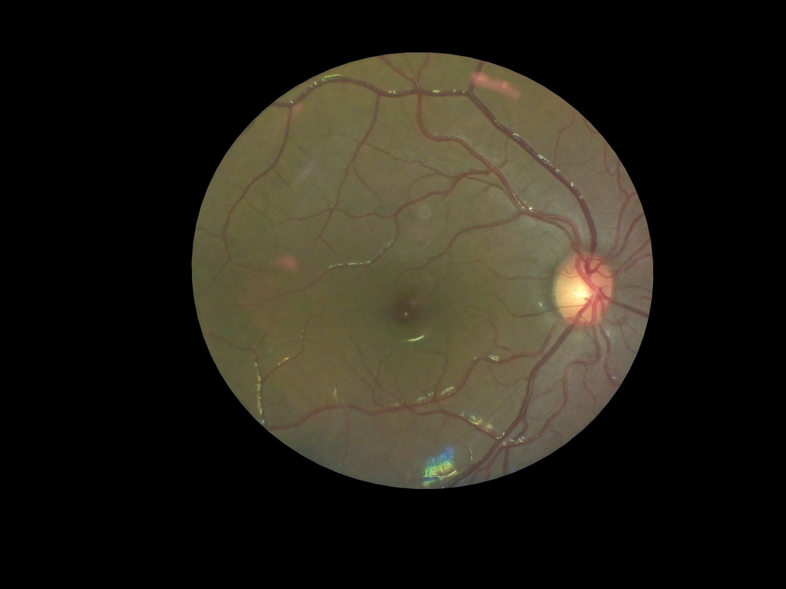
The test results were very encouraging. Though we designed the device to work on people with negligible refractive error, we realized that by varying the distance of the device from the eye, we could capture retinal images of people with positive eye-lens powers.
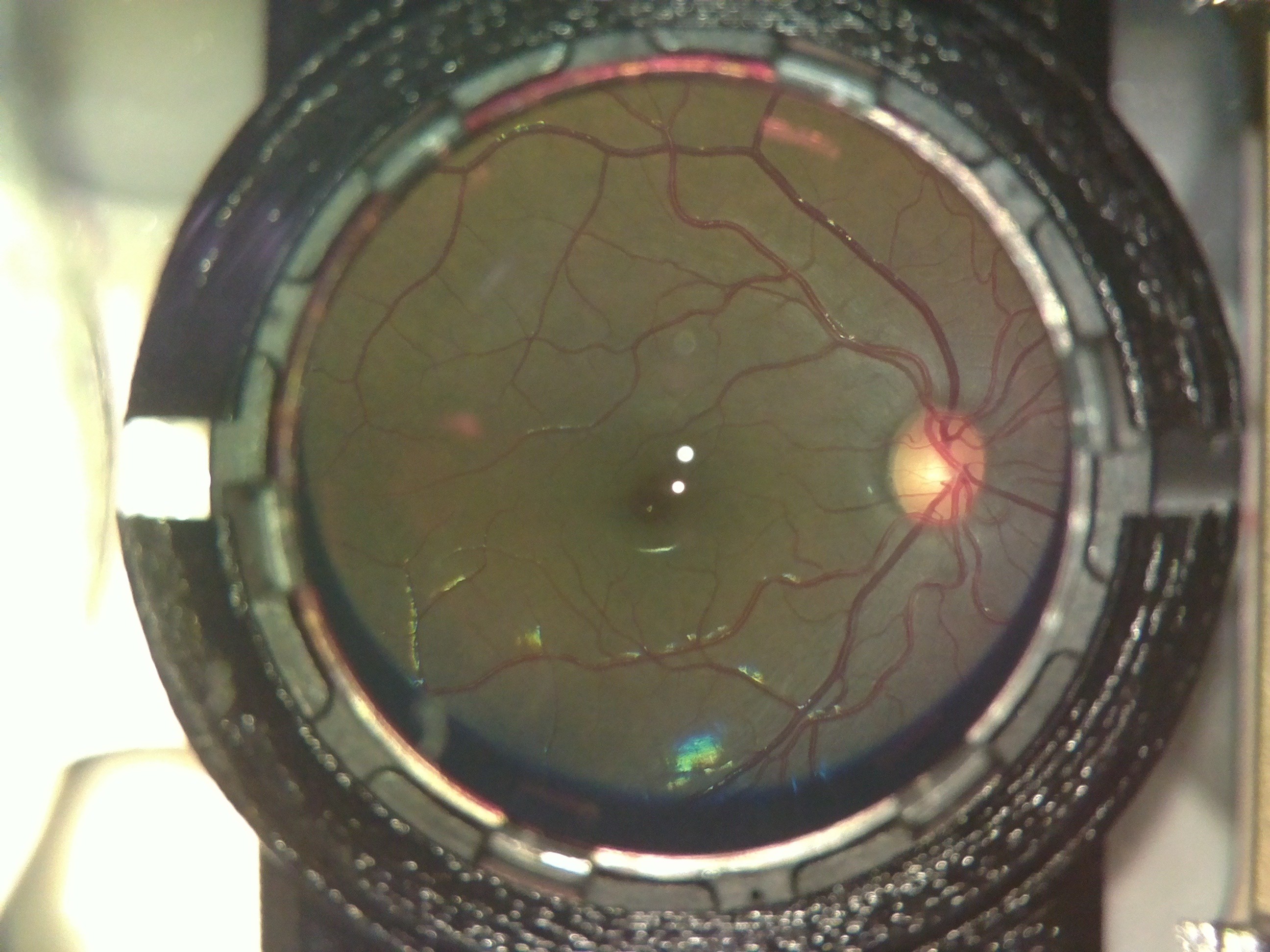
The following image was captured on a person with power +4.
![]()
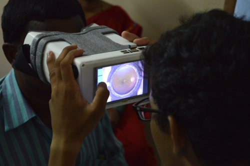
After trials in the lab, we took the device for trials at a secondary center of LVPEI in rural Telangana, India.
Here is a picture of the device being used on a dilated, informed, consenting patient at the center:
![]()
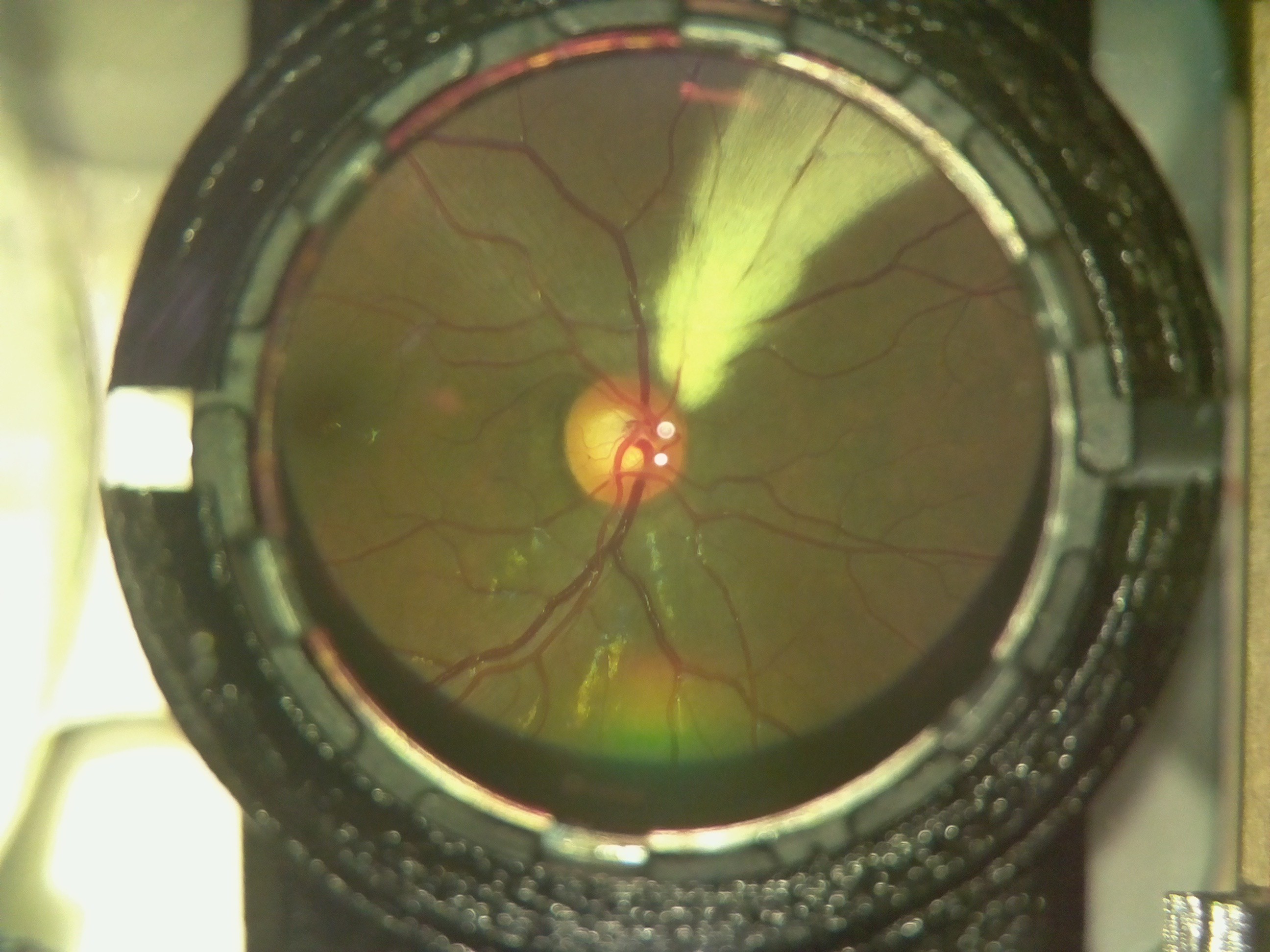
The device performed flawlessly. This was the first time we got to use the device on patients with retinal defects and the results were outstanding.
Here is an image of a myelinated retina. Notice the white patch on the fundus.
![]()
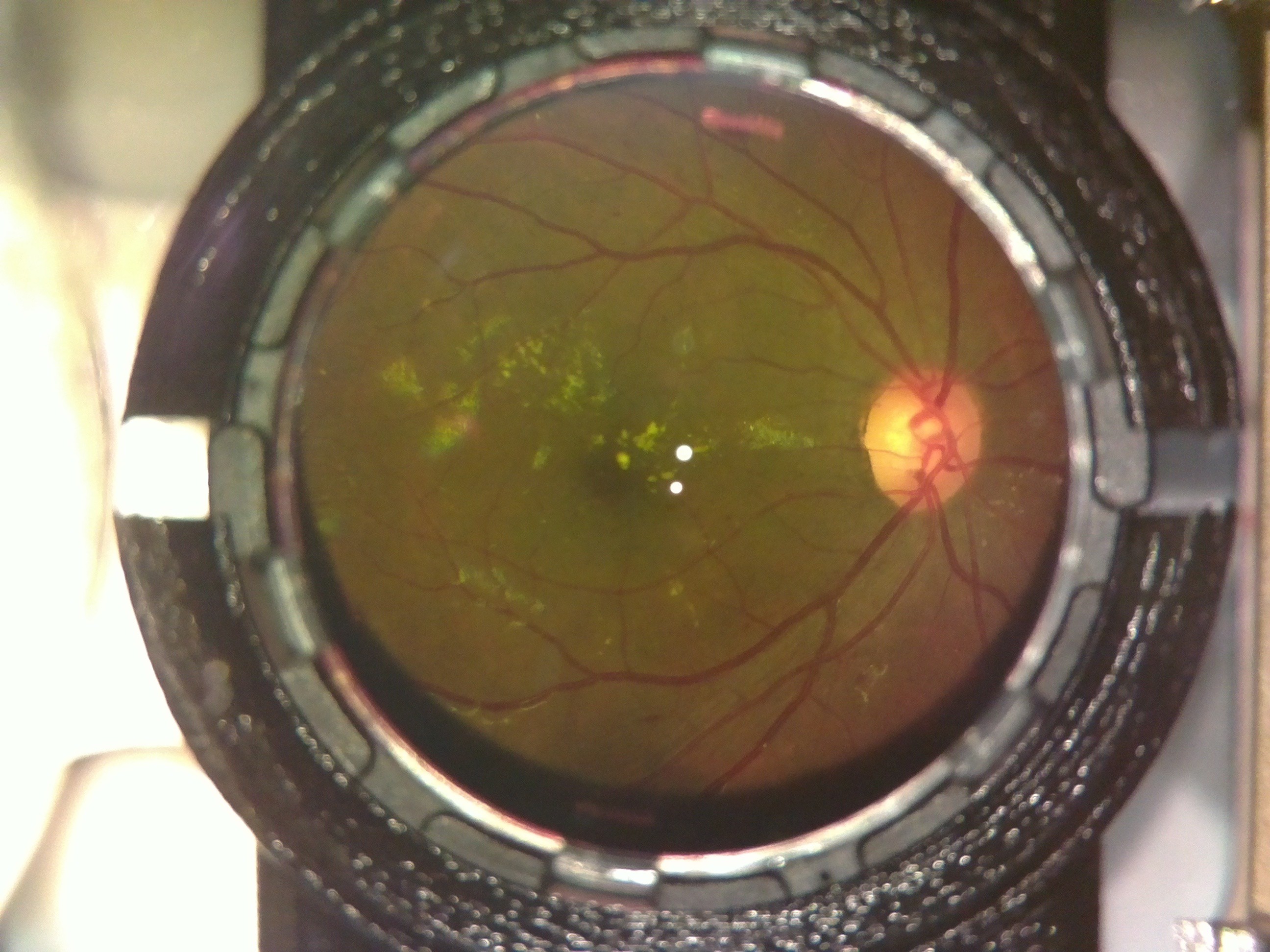
A case of diabetic retinopathy we discovered. Notice the flake like formations on the retina.
![]()
The Doctor at the center confirmed both cases for us. OWL had successfully screened its first Diabetic Retinopathy patient; indeed a huge milestone for the project!
-
Safety Limits and Tests for OWL
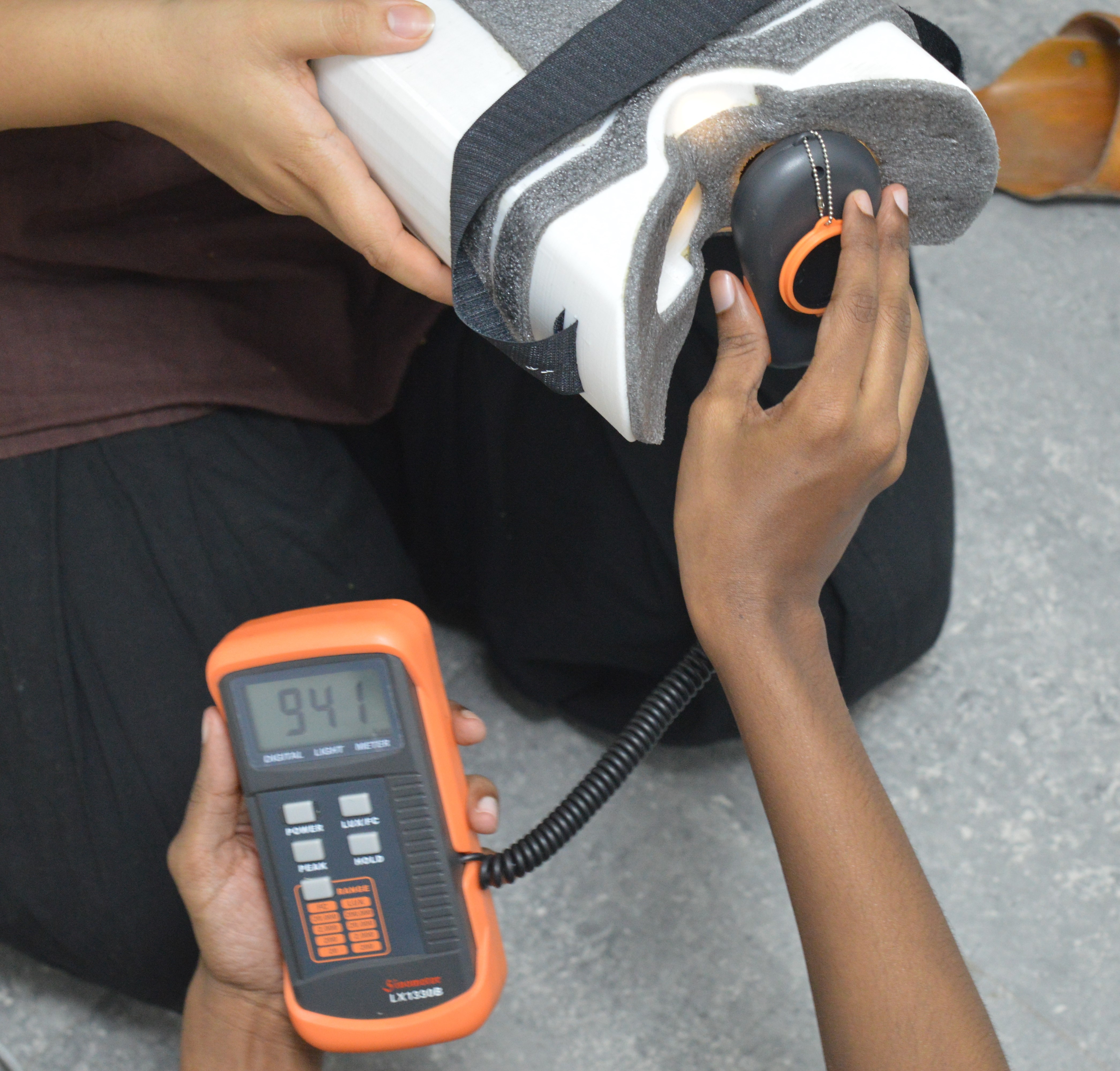
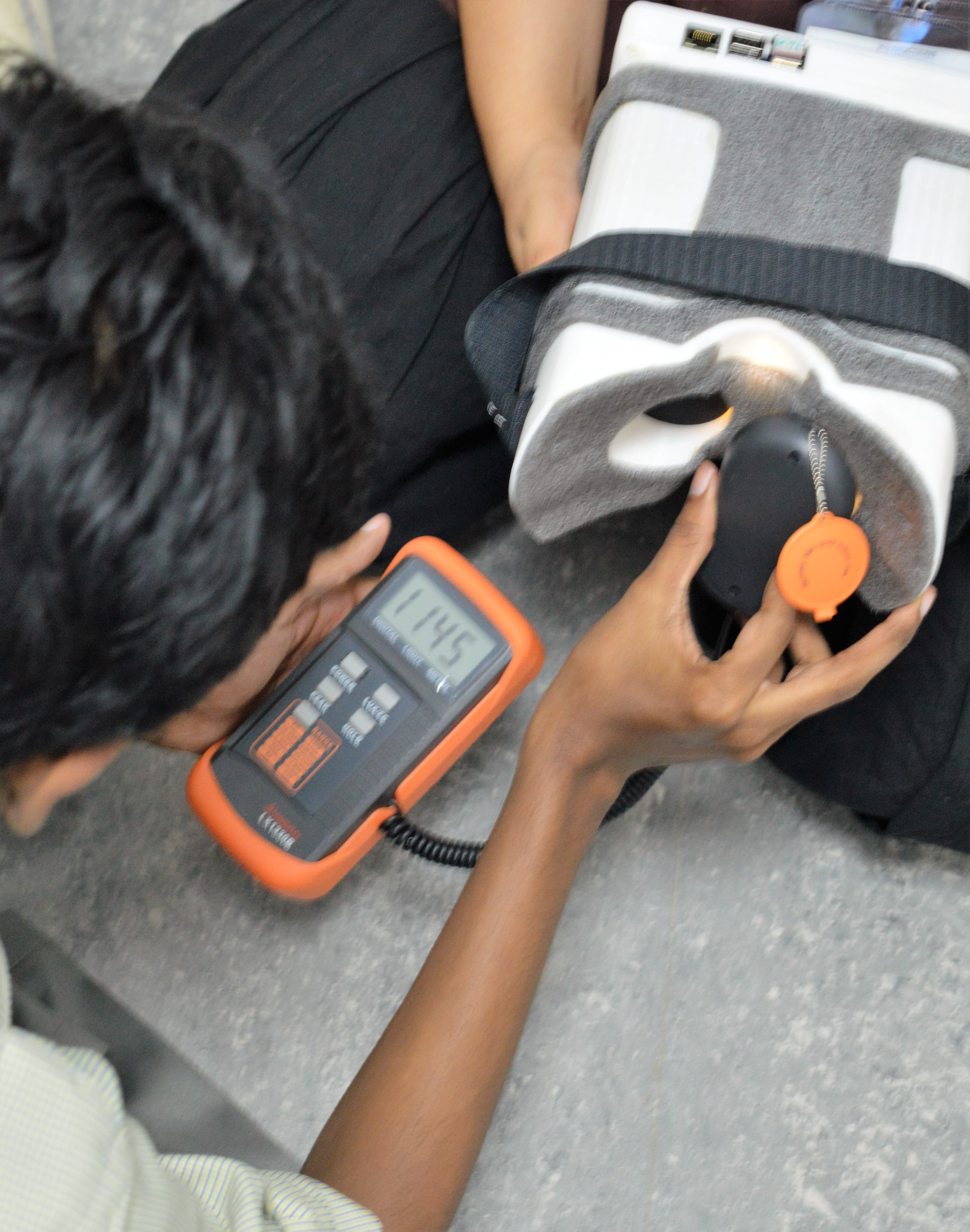
07/12/2016 at 09:38 • 0 commentsLED Used : Lexicon 3 Watt LED Warm Yellow.
The luxmeter Sinometer LX1330B was used for all calculations.
The corneal diameter is the maximum spot size at the most focus point of the illumination source. The point of maximum illumination is found by moving a white paper in front of the 20D eyepiece lens until a sharp image of the illumination LED is formed in the place.
The testing is done both in a dark room and inside an illuminated room. Although only images of the Luxmeter in lighted room is shown.The maximum intensity found was around : 1210 lux. [Using the PEAK function of the luxmeter]
The values mostly fluctuated between 950 - 1140 lux when the lux meter was moved around the illumination areas.
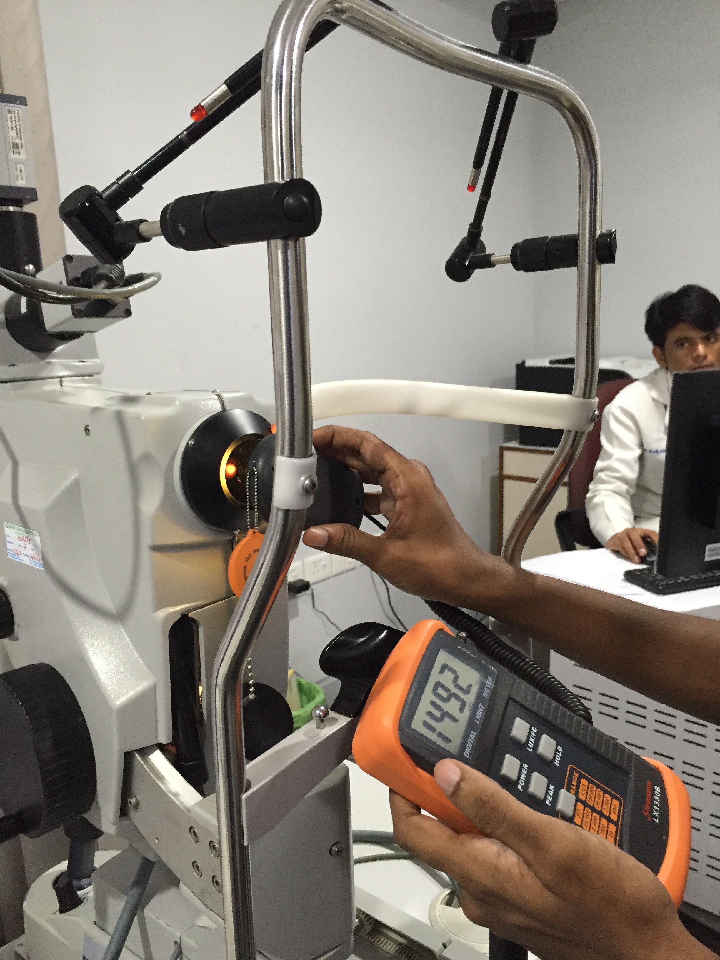
Additionally, to make sure we were on the right page, we used the lux meter to test on a hospital funduscope and it gave an Illuminance of 1450 - 1510 lux.
This established that the device is safe enough for use on human eyes. On comparison with ISO standards, we found that we were well within the limits of irradiation which can cause any form of retinal damage.
We also found that the device is as luminous as an overcast sky.
(Ref : https://web.archive.org/web/20131207065000/http://stjarnhimlen.se/comp/radfaq.html#10 ) -
Removing undesired reflections/spots
06/25/2016 at 09:50 • 0 commentsHey all!
This is another project log to update the latest developments of OWL (Just in case you forgot, we call it OWL because, well, Open Indirect Ophthalmoscope, OIO).
So, since the last time I made a log, we’ve been working on-
- -making an elegant GUI for the device
- -improving the image quality, playing around with optics
- -removing the reflections caused in the image.
- -a polarizer arrangement to remove the formation of the spots
- -mosaic stitching.
This, besides the basic tweaks every now and then.
The GUI will be covered in detail by Ayush Yadav in a different build log.
Coming to the optics, we basically were experimenting different ways to somehow eliminate the bright spots being formed on the image.
Once the device was assembled and tested, we realized that the reflections wouldn’t stop forming unless we use a polarizer setup (Will be explained later in this same log).
Each LED was forming four reflections, two because of the mirrors and two because of the two surfaces of the 20D lens we use.
So we decided to try two things:
A glimpse in the implementation and methods of these two approaches areas follows:
Polarizer arrangement:
Polarizers are fundamentally optical filters, in the sense that they block waves of all polarizations except for one, giving a polarized light beam from a mixed polarized light beam.
The idea was to put polarizers of one orientation in front of the LEDs we use for illumination and another polarizers of perpendicular orientation on the camera lens. What this does is, when the light emerges from the LEDs and passes through the polarizers, it has just one polarization of the light passing through. And the camera has a piece of polarizer perpendicular to the orientation of the LEDs. So the spots will sure form, but the camera won’t detect them. Because the polarizer (in front of the camera) will block that polarization of light. So although the spots do exist, they don’t show in the image captured.
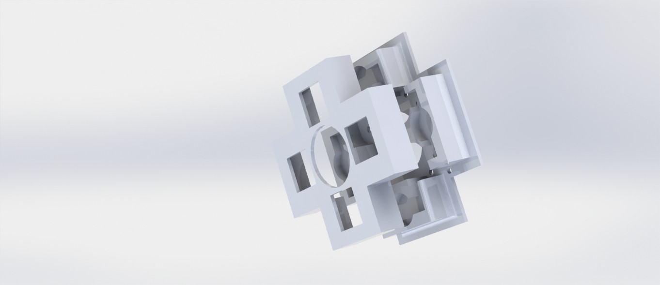
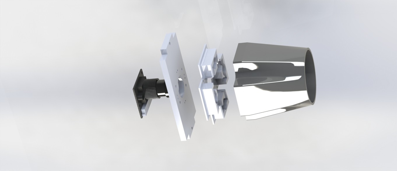
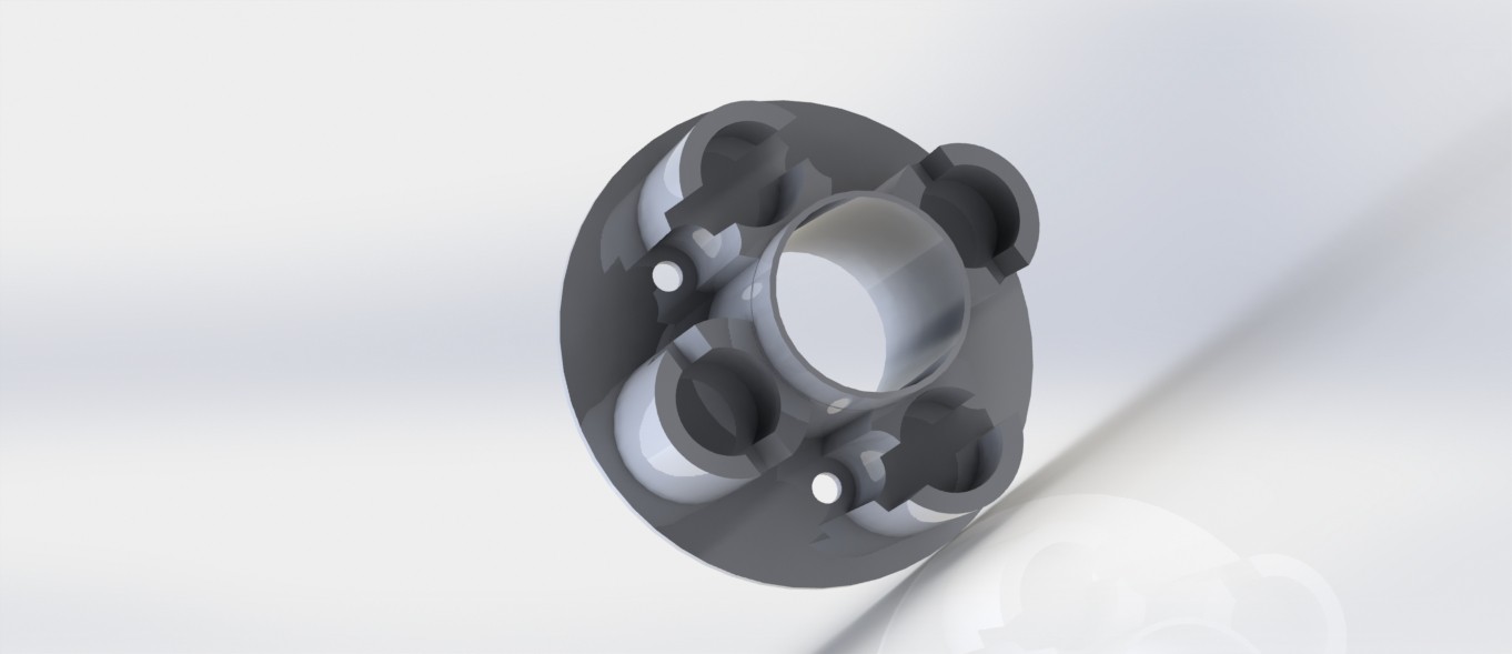
For this, an assembly was 3D printed. With the dual purpose of holding the LEDs in their calculated place and also housing safely the polarizers in their place, the assembly has two parts, elegantly snapping into one another. This is then screwed onto the camera holder. The image shown is of the final iteration that had been used.
And this is an exploded render of the camera assembly with the hood, the LED holders, etc.
Like we expected, the polarizer assembly worked. The spots did not appear in the images. But we had to scrap the idea anyway. Because for some reason the brightness was hampered. We could visibly see a ‘+’ like shape form in the image which was because of relatively poorer illumination in that part of the image. We’re guessing this has something to do with the fact that our eyes also have a very thin layer of polarizer on them.
Mosaic-stitching images
Out of ideas, we took the last resort. Stitching two images together. The plan was to two images with different LEDs on, thereby removing the areas of the image with the spots.
So, we tried it out with the initial two-LED system only to realize that it is pointless to stitch the images we were getting. This is because one of the spots forming by each LED were being converged by the 20D lens to an extent that they overlap. And when overlapping, stitching can’t possibly help.
So we then tried another illumination system, this time with four LEDs, two along each of X and Y axis, and then switching two LEDs on at once. That is, we switched the horizontal LEDs once and take an image and then with the vertical LEDs on, we take another image. Because the LEDs are now along perpendicular axes, the spots formed will be at an angle of 90 degrees, so making the images easy to stitch.
This is where we started using a 4 LED system. This again, gave a disappointing result. The horizontal LEDs hardly gave any illumination of the fundus. We gave it another try with reduced distance between the camera lens and the LEDs to the least possible. A render of this spatially optimized part is below. This also proved to be useless. So, we had to scrap this idea too.
Next, we briefly experimented with a shape X instead of + because we expected an X might give a better illumination when compared to the + orientation. Although we did getter better illumination, it came with the dark Plus at the center of the fundus again.
So, having no point in using 4 LEDs, we shifted back to the 2 LED system.
And that is what we’re using now too. With the hood in place, we’re getting two spots instead of four, which is progress, but we’re yet to remove the remaining two.
-
Adding Keyboard functionality and making dynamic Image save path
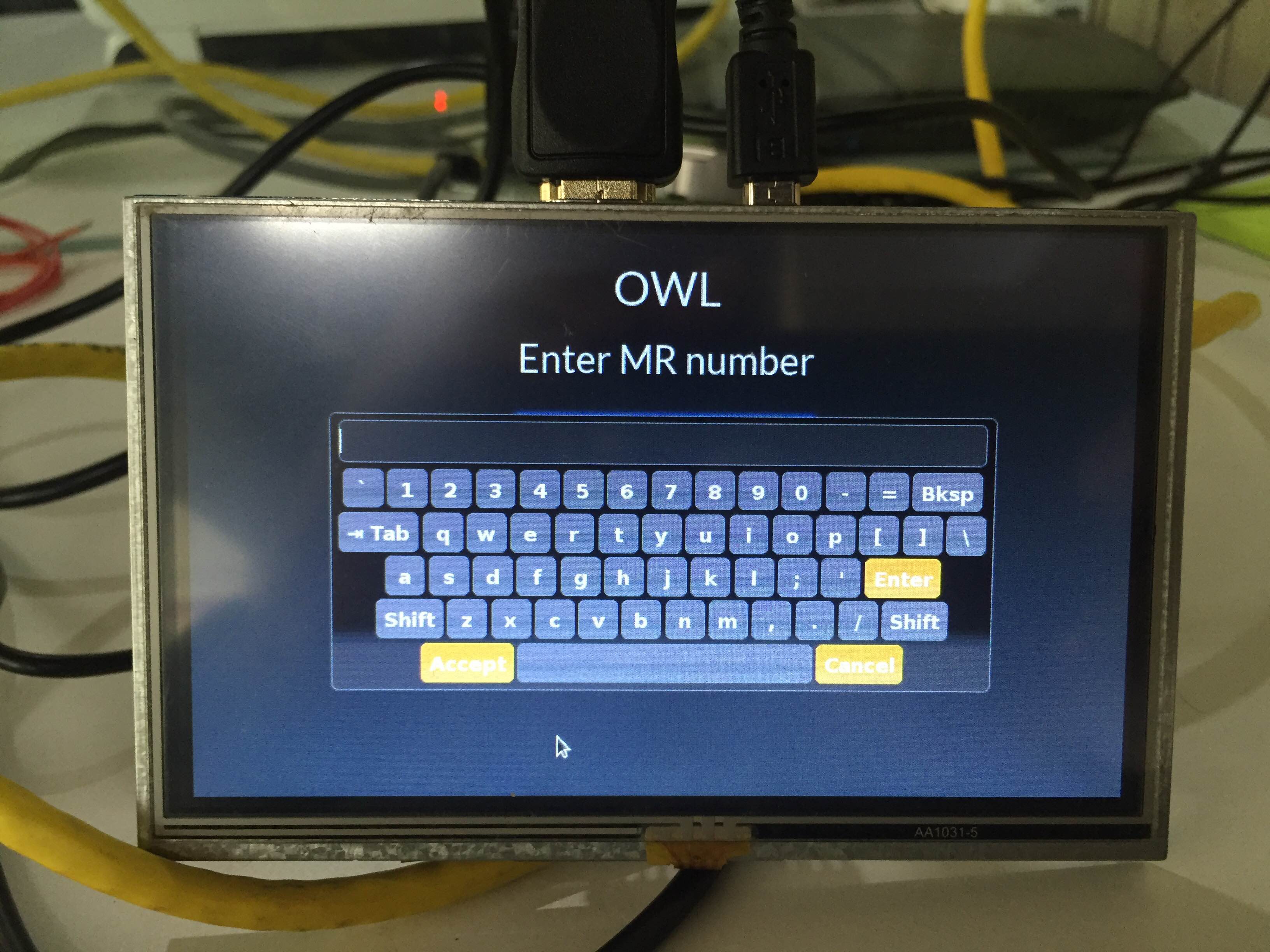
06/13/2016 at 10:20 • 0 commentsSo, the next thing that was implemented was a JQuery keyboard.
It pops up when you click on a text box input field. You can accept and then submit the query.
The code used for the keyboard was from the following source.
https://mottie.github.io/Keyboard/
The following are the images relating to it:The page is shown as above.
On touching the text field a keyboard appears which can be used for touch inputs.
The other thing that has been corrected is the path for saving images. Till now we were saving the images on a static path. But now the images will be saved in the root folder of the application in /images directory.
A separate directory is created for every patient.
Open Indirect Ophthalmoscope
An open-source, ultra-low cost, portable screening device for retinal diseases




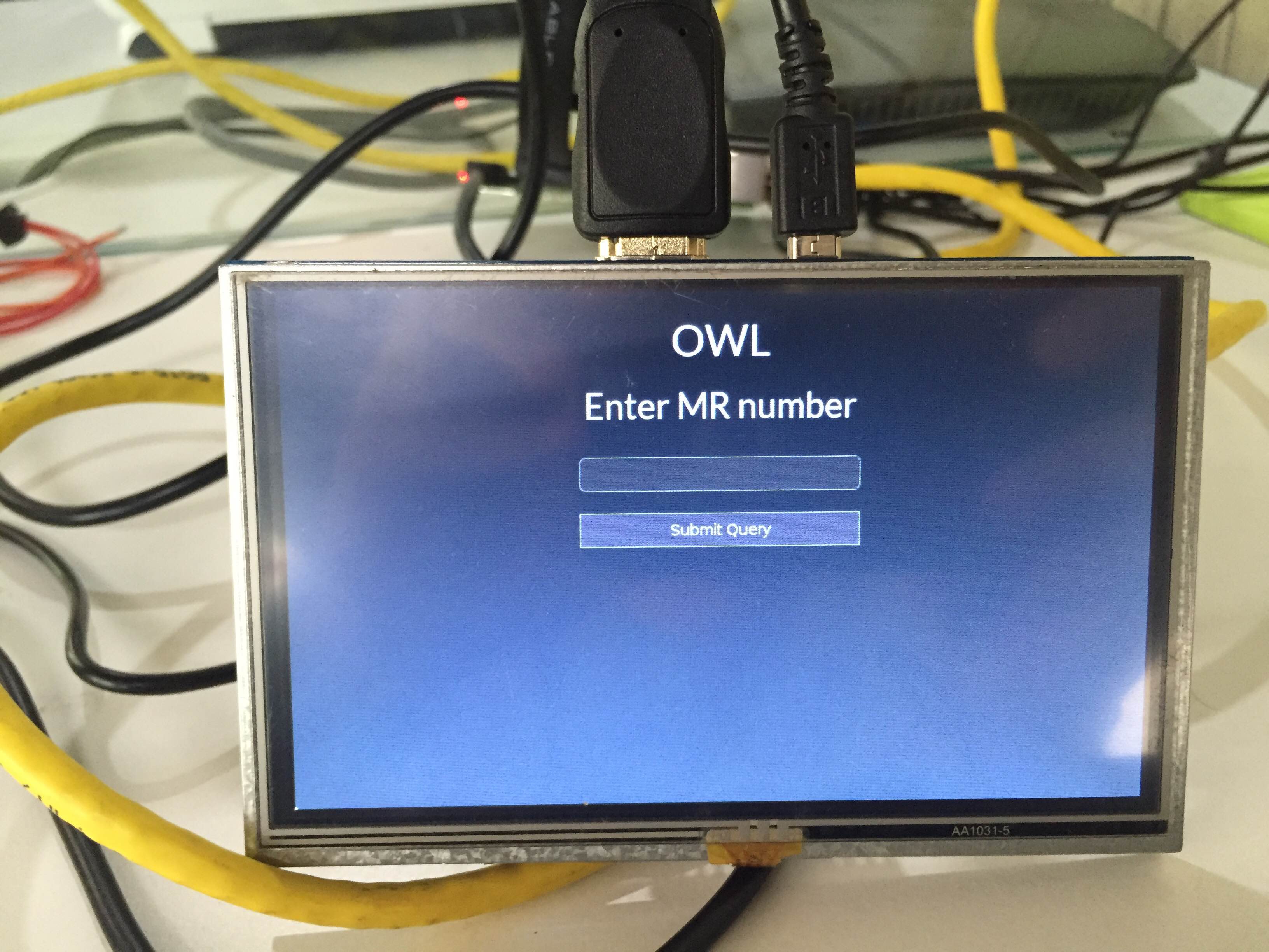 The page is shown as above.