-
11Step 11
Time to start putting together the low-side driver board with the CAT4101s. First step is to install the connector on the 11 x 8.5 cm protoboard. This is the spec'ed component, but if you can't find one that size, you can use another one up to 11.5 cm in the long (horizontal) dimension, and 11 cm in the short (vertical dimension), which will fit in the enclosure I've been using. Bit smaller will work, but if it's too small you may have problems getting all the components and wiring to fit. If you use a larger enclosure, then you can use a larger protoboard; don't go smaller with the enclosure, or the controller boards may not fit.
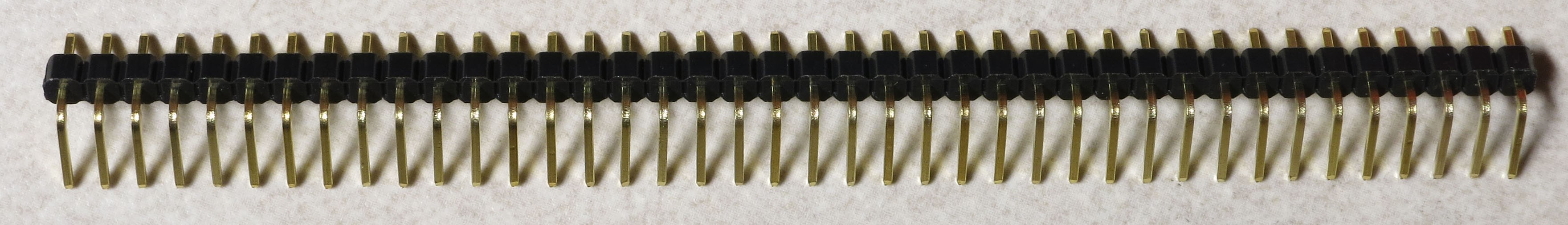
The connector is a right-angle male header, which comes in a 40-pin length:
![]()
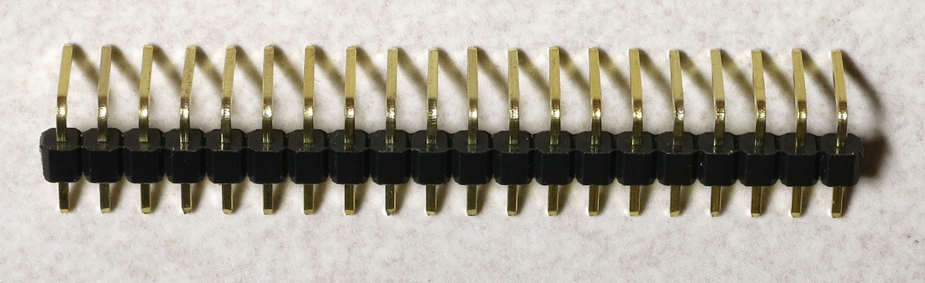
We need a 20-pin connector, but it's easy to break the 40-pin in half:
![]()
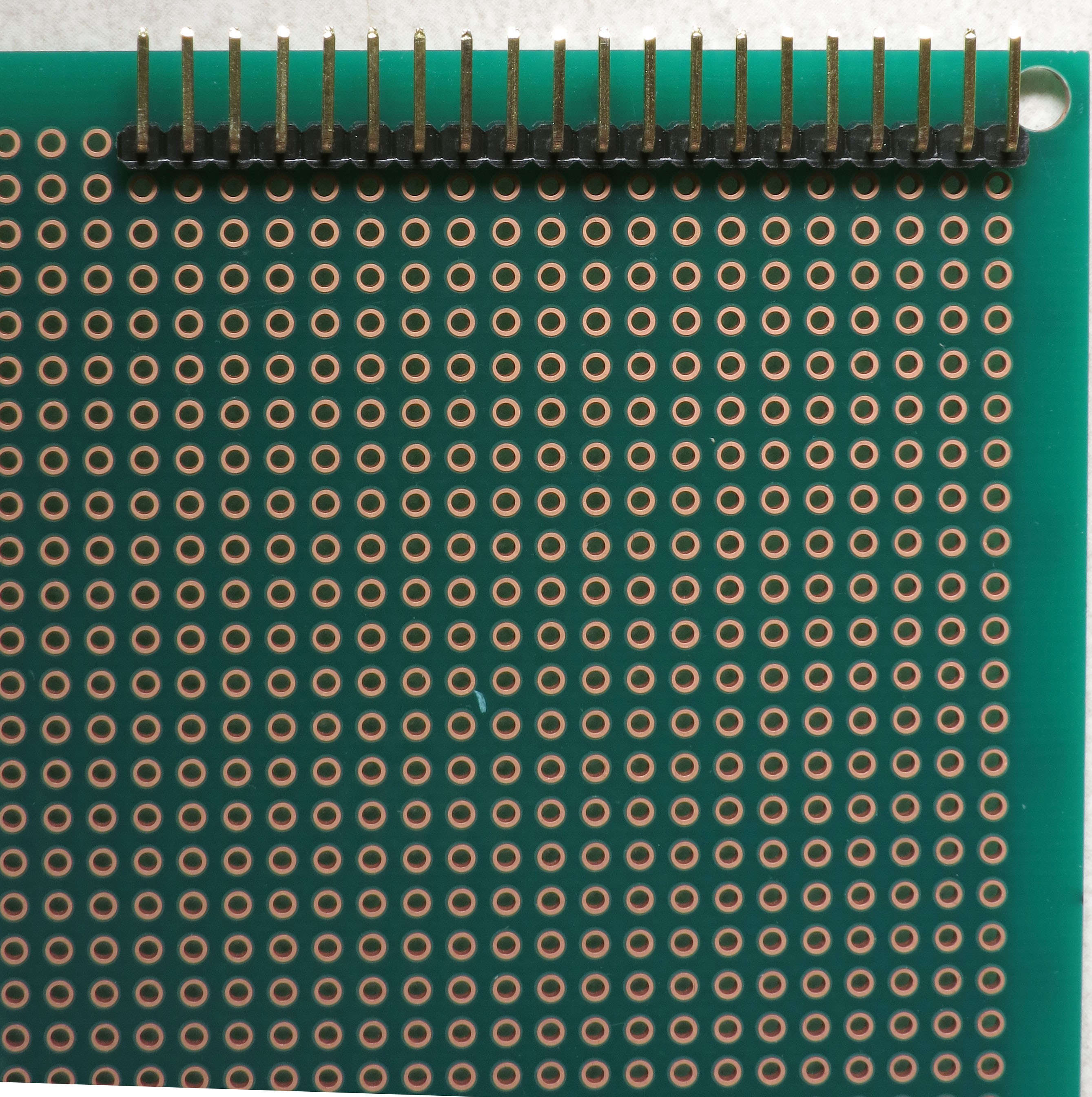
You're going to be soldering the connector to the protoboard as far to the upper left as you can get:
![]()
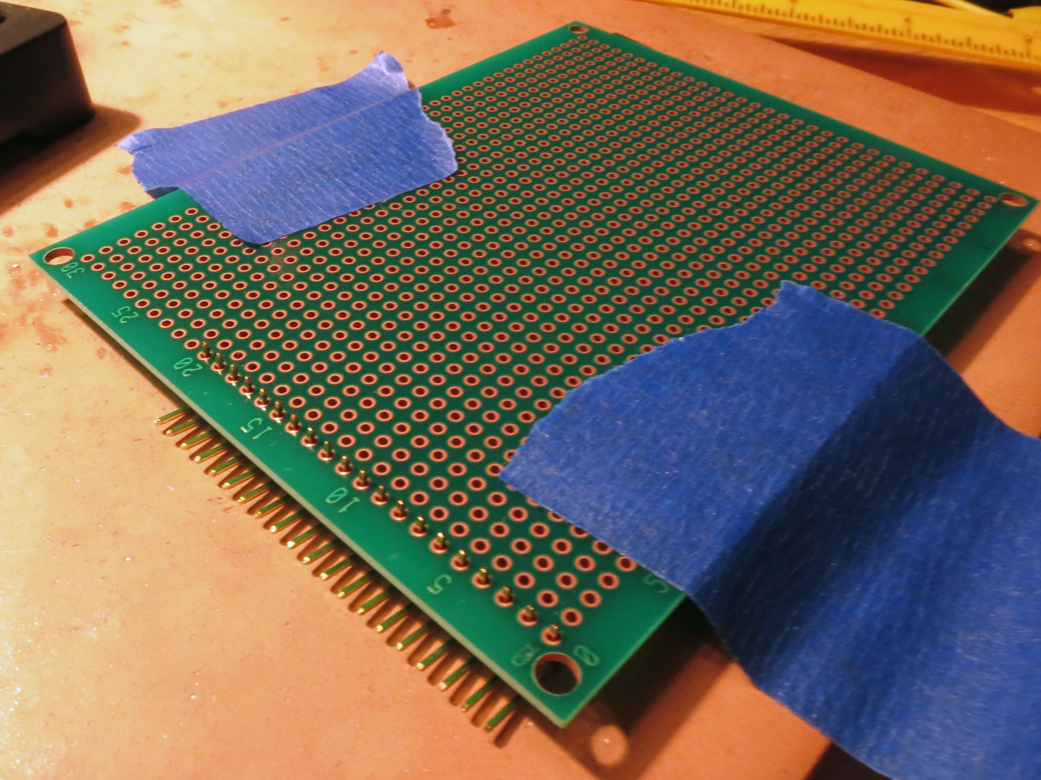
The short pins go into the protoboard for soldering. The plastic base of the pins needs to be flush with the protoboard, so that the long pins are parallel to the protoboard. It can be tricky to do this. I approach this by inserting the connector into the board, flipping it upside down, placing it on the soldering work area, and taping it down:
![]()
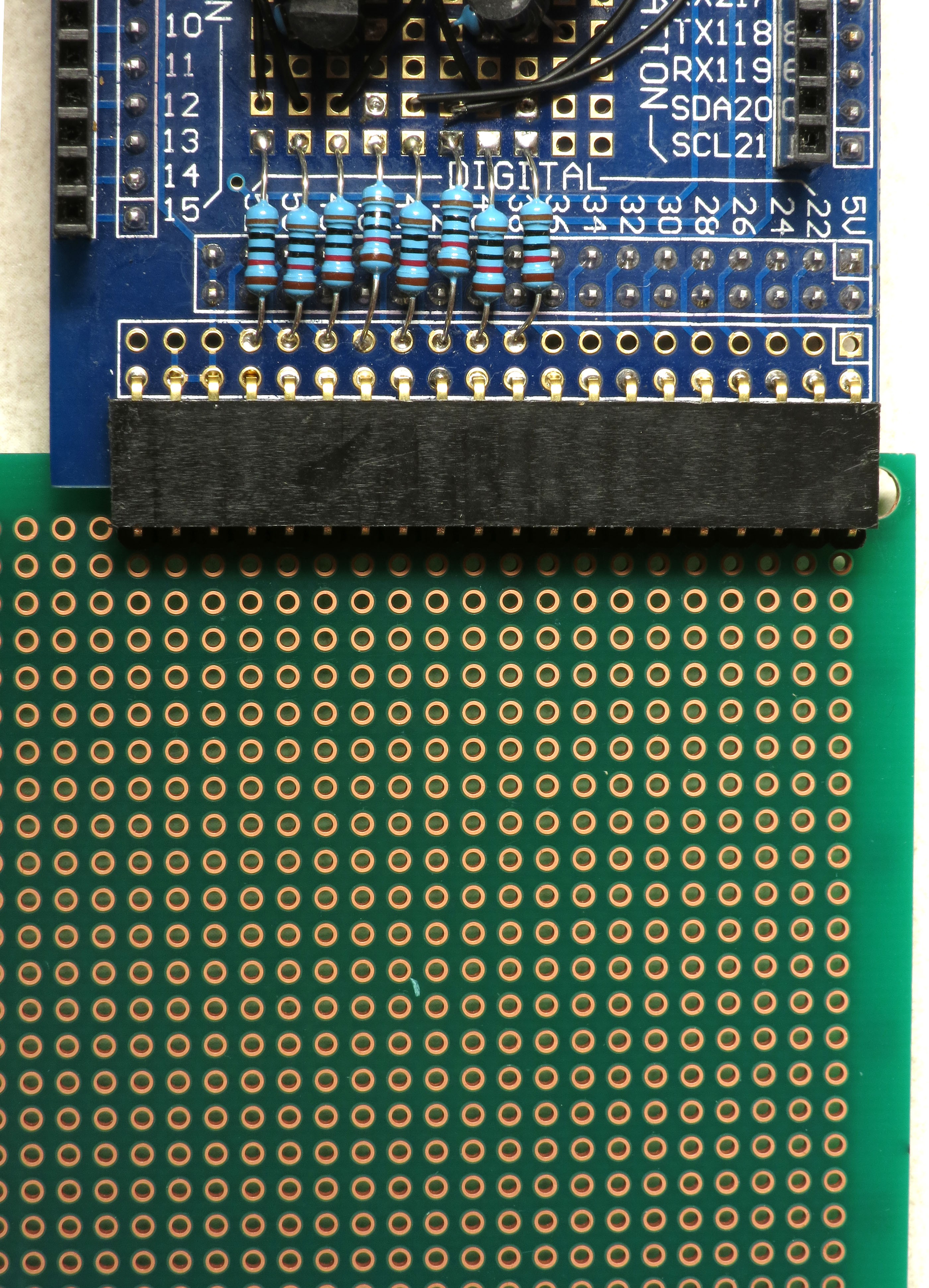
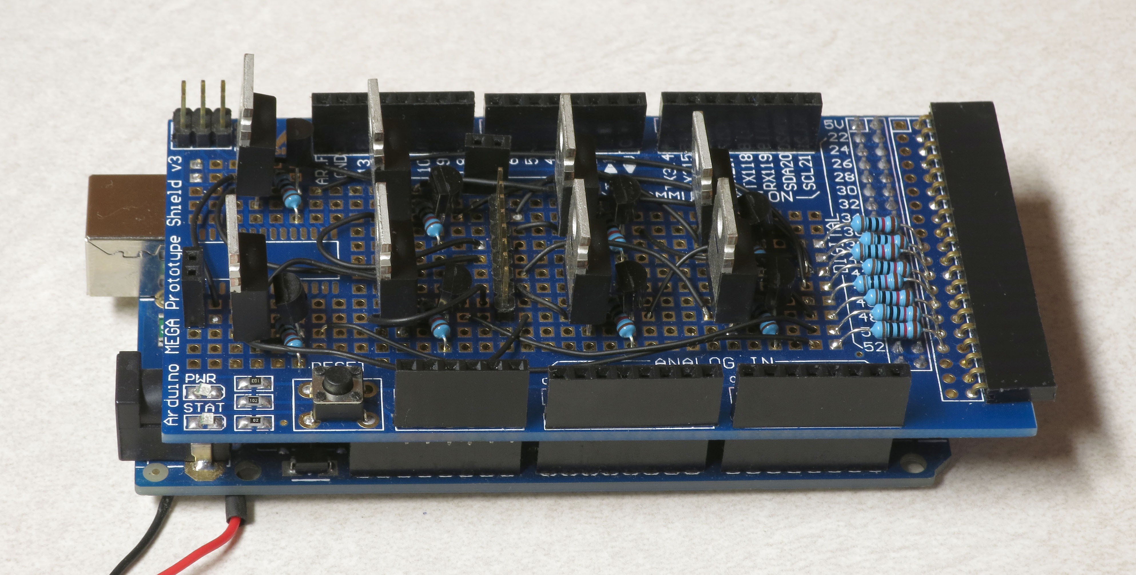
Solder a pin at one end, then remove the board and see if the connector is flush with the board. If not, reheat the solder connection and press on the connector to make it flush with the board. Caution: Make sure you don't do what I've done a couple of times, and press on the same pin that's touching the soldering iron ;-). Check again to see if it's flush. If yes, solder the pin at the opposite end, and check to make sure that it's flush as well. When both ends are flush, solder one more pin somewhere near the middle of the connector, and make sure that's flush, too. If you've done it right, the male connector on this board should plug cleanly into the female connector on the MOSFET shield you assembled in the previous steps (no bending required):
![]()
-
12Step 12
Note: In schematic wiring drawings, the wire lines are drawn from one hole on the shield or protoboard to another. The wires connecting these holes should have the insulation stripped from their ends, and have the bare lead inserted into the hole. The bare lead should then be connected to the specified nearest component/connector lead.
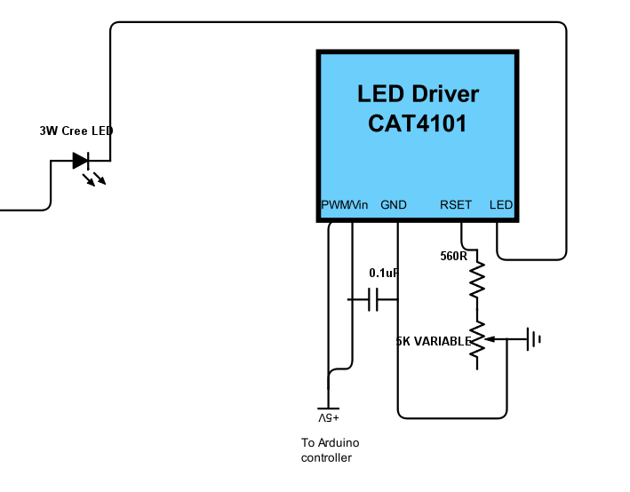
Time to install the CAT4101 LED driver breakouts and associated components onto the protoboard. Here's a crude circuit schematic:
![]() There are 5 leads on the CAT4101. From left to right:
There are 5 leads on the CAT4101. From left to right:1. EN/PWM: Enables the current from the LED driver. PWM is pulse width modulation, a way to control apparent light intensity by varying the input signal voltage - not used in this system.
2. Vin: Powers the chip with +5V.
3. GND: connects to ground.
4. RSET: Connects to a resistor that sets the output current per this curve (from the datasheet):
![]() 5. LED: Connects to the ground lead of the 3W LED you're lighting up.
5. LED: Connects to the ground lead of the 3W LED you're lighting up.In my circuit, EN/PWM and Vin are shorted together, and both are connected to an Arduino output that supplies +5V. I tried a constant +5V connection to all the CAT4101 driver Vin pin 2s, and a separate Arduino connector to all the EN/PWM pin 1s, and wound up with weird issues like multiple LEDs lighting up when only one should have. Shorting 1 and 2 together and hooking them up to the Arduino pin output fixed that problem.
The 0.1 uF capacitor between the input voltage and ground is recommended by the manufacturer to reduce input noise. I'm guessing it's probably not necessary in this use case, but it's cheap to play it safe. Plus, it makes some upcoming wiring connections a bit easier.
The RSET graph above shows the current going as high as 1.2 A, but the recommended max current for both the CAT4101 and the 3W LEDs is 1 A, which the datasheet says corresponds to a resistance of 549R. The 560R resistor in the current is the closest higher standard resistor value, and is there to make sure you don't accidentally send too much current through the CAT4101 and LED. The 5K variable resistor is there to let you adjust the current to a specified value. Three reasons for this:
1. The current v. RSET curve is steep at lower resistances, so even small circuit variances between different CAT4101 circuits can result in significant differences in current. The variable resistor lets you set a specific current for every CAT4101 circuit, which insures that all LEDs will have the same light intensity.
2. If you're in a remote location and running from battery power, turning down the intensity will prolong battery life. Your exposure times may need to be a fraction longer, but that shouldn't add too much extra time to the cycle.
3. When using USB microscopes, the light intensity at full 1A current is so high that it can saturate the image sensor. Turning down the current reduces the intensity to a usable level.
Here's the protoboard with connector (from the previous step), with the locations for the CAT4101s circled in red:
![]()
This is with the recommended protoboard. If you use a different size, you'll have to reposition these slightly. But read all the following instructions for your protoboard, to make sure the new positions don't interfere with upcoming components or wiring.
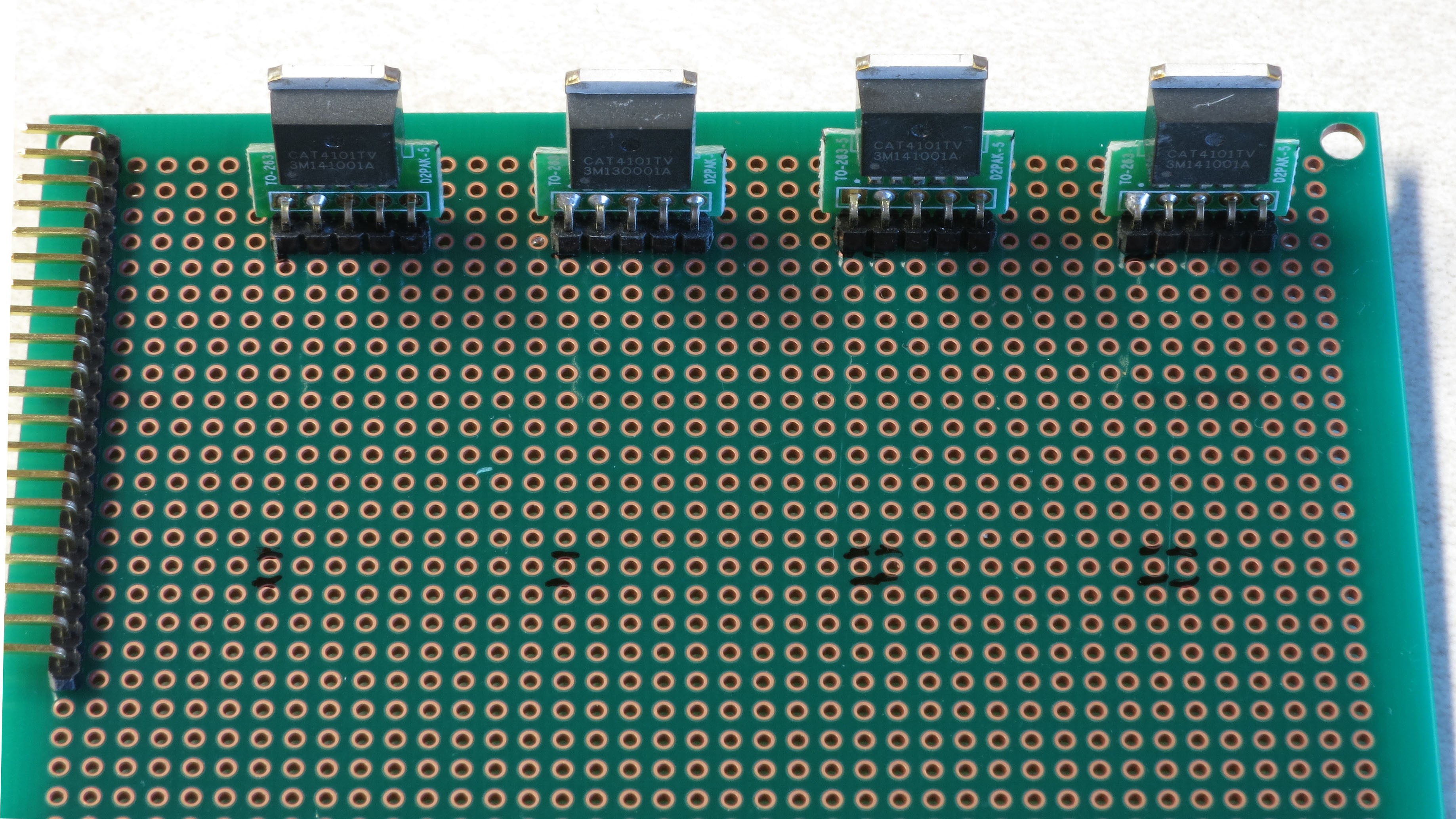
I usually start by installing 4 CAT4101s on the top row:
![]()
By not installing the second row right away, I get a little extra room in front for access. The black marks are where I marked the pin 1 position for all the CAT4101s. Notice the extra marks on the right - that's where I got it wrong the first time. Measure twice, solder once ;-). I start by soldering the pin 1 lead in place, then flipping the board over and seeing if the CAT4101 breakout is flush with the board and perpendicular. Spoiler: it almost never is. Touch the soldering iron to the pin 1 connection to re-melt the solder, then re-orient the breakout board manually until it's flush and vertical (as seen above).
Next, install the capacitors. Push the two capacitor leads into the holes next to CAT4101 pins 2 and 3, on the back side of the board, like this:
![]()
Push them in as far as you can - the more capacitor lead you get on the bottom, the easier subsequent steps will be. Flip the board over, and position the capacitor leads like this:
![]()
The lead next to the center pin 3 (GND) should be laid flat and straight touching pin 3 and extending beyond. The lead next to pin 2 (Vin), should wrap around pin 2, and then be laid flat against pin 1 (EN/PWM). Solder the leads to the pins they're next two; make sure both pin 1 and pin 2 are soldered to the lead next to them. Don't trim the excess leads - you'll need them in a bit.
Next, install a 560R resistor on the front side of the chip, next to pin 4 (RSET):
![]()
Orientation doesn't matter with resistors, but my OCD usually compels me to make sure they're all oriented the same way. Flip the board over, and flatten the resistor leads like this, but don't solder them yet:
![]()
This pic also shows how the capacitor leads should have been soldered (missed taking that pic).
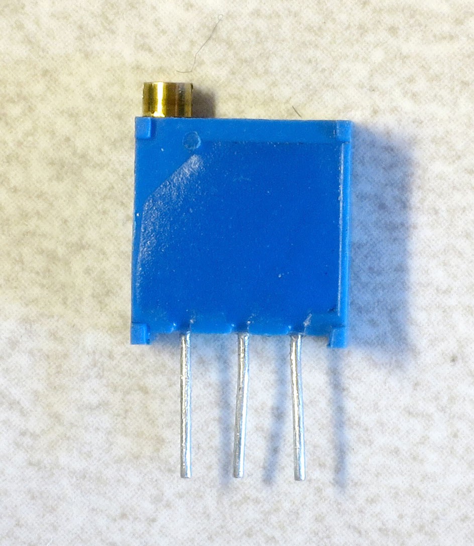
Now take a 5K trim pot:
![]()
Cut off the lead furthest from the screw on top, converting it into a variable resistor:
![]()
Insert it next to the GND pin (pin 3) on the top of the protoboard:
![]()
It's a snug fit, but not soldering the 560R resistor means you should be able to nudge it to the side and make everything fit.
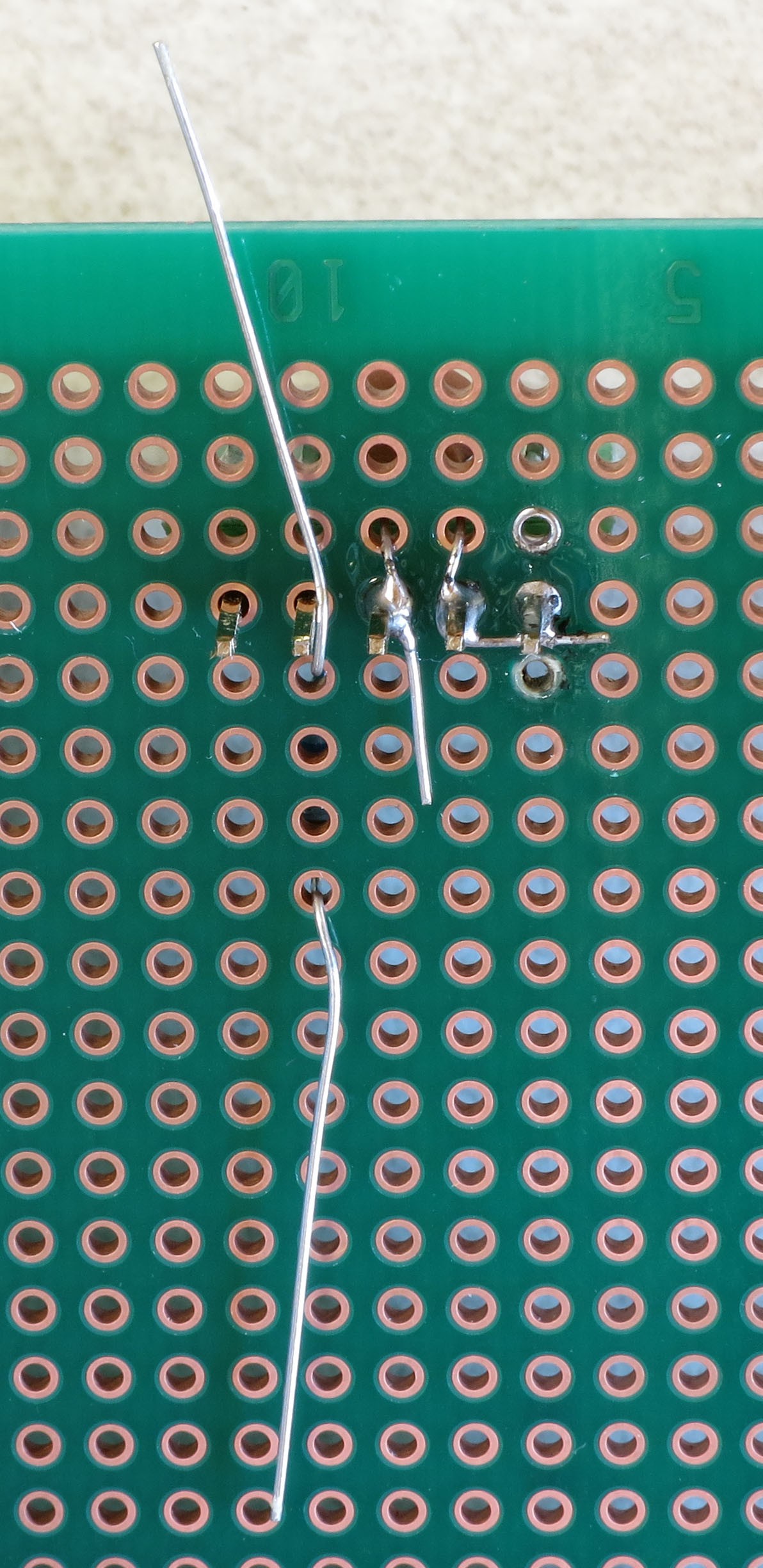
Now flip the board over, and arrange the variable resistor leads this way:
![]()
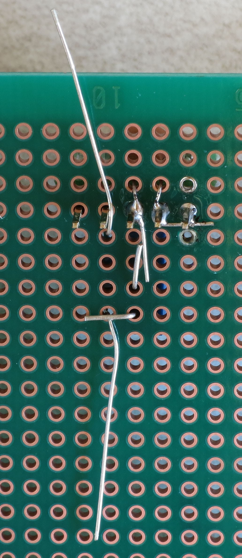
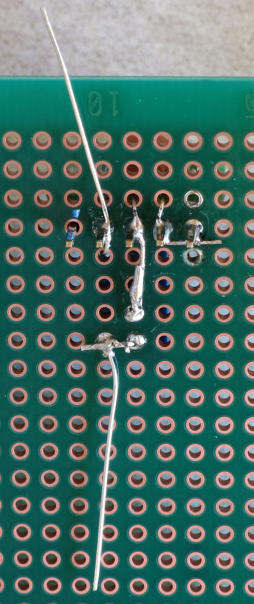
The variable resistor lead furthest from the CAT4101 chip should be bent over to touch one of the 560R resistor leads. The variable resistor lead closest to the chip should be bent towards CAT4101 GND pin 3, overlapping and touching the capacitor lead that's already soldered to pin 3. Now solder the 560R resistor lead at top to pin 4 (RSET) on the CAT4101, solder the bottom 560R lead to the variable resistor, and solder the other variable resistor lead to the capacitor lead. Should look something like this:
![]()
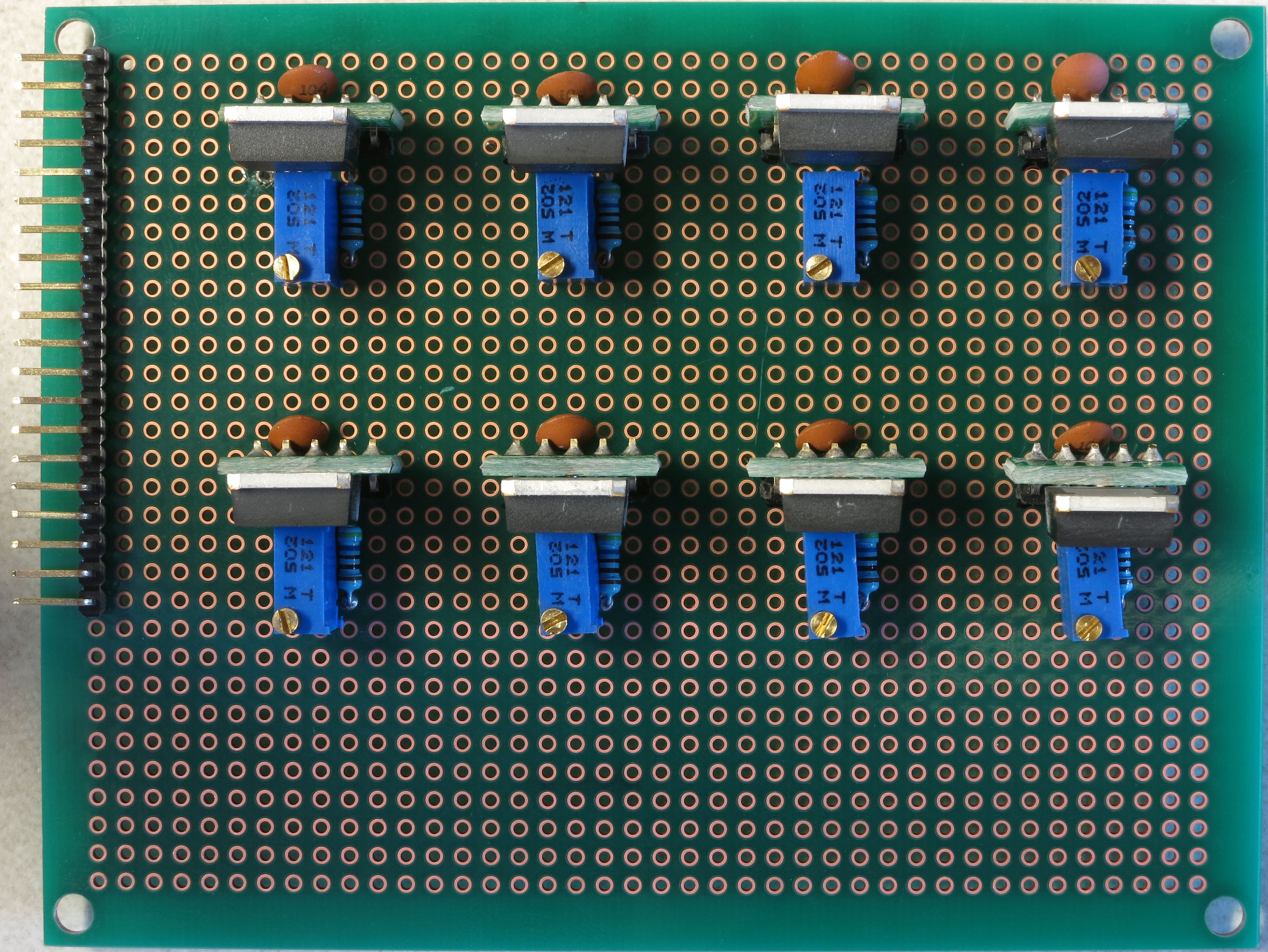
Trim off the excess resistor leads, and you're done with this CAT4101 circuit. Repeat for the other 3 CAT4101s in the first row:
![]()
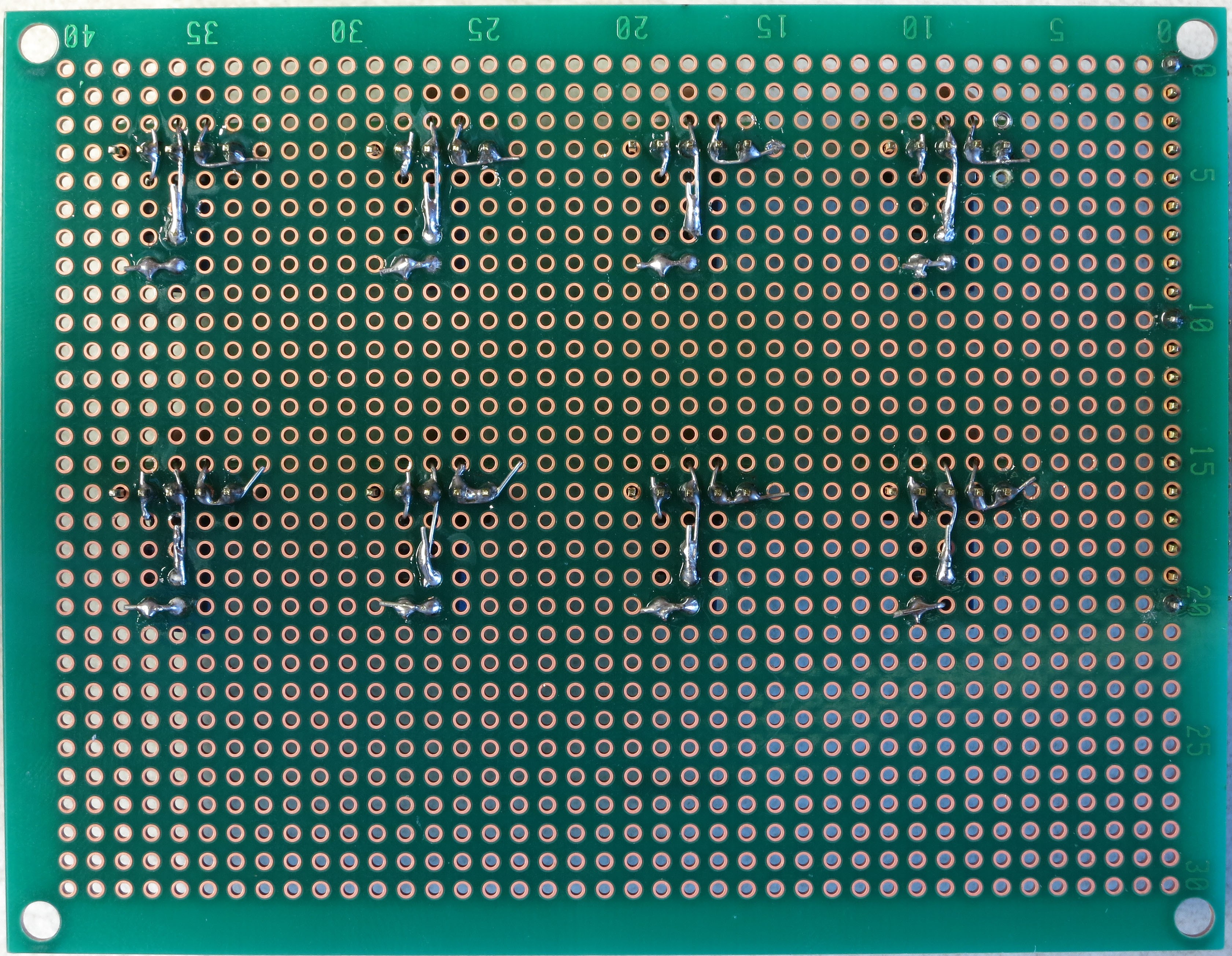
Which should look like this on the bottom, after all the soldering is done:
![]()
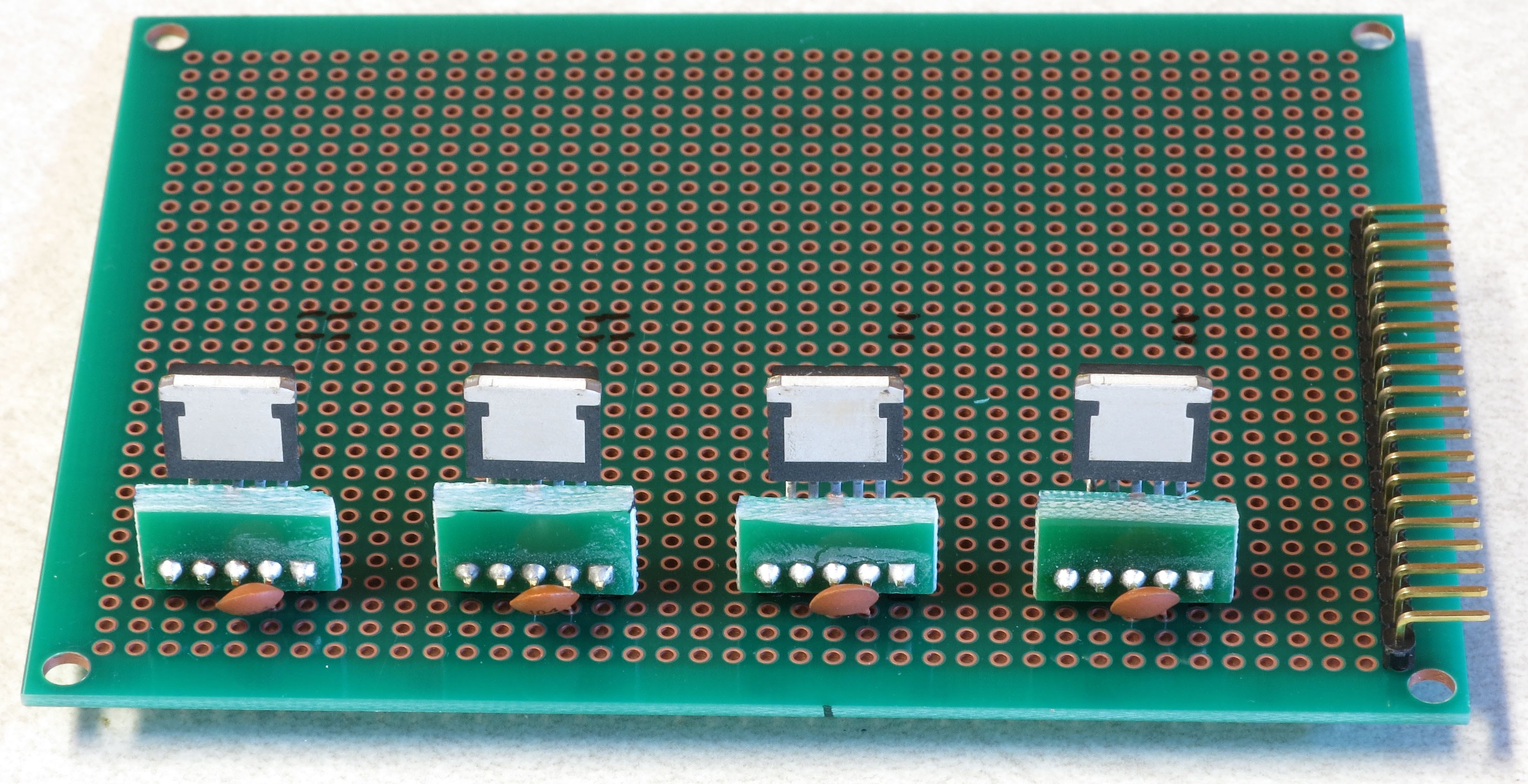
Now repeat the process with the second row of CAT4101s. Install the CAT4101 breakouts:
![]()
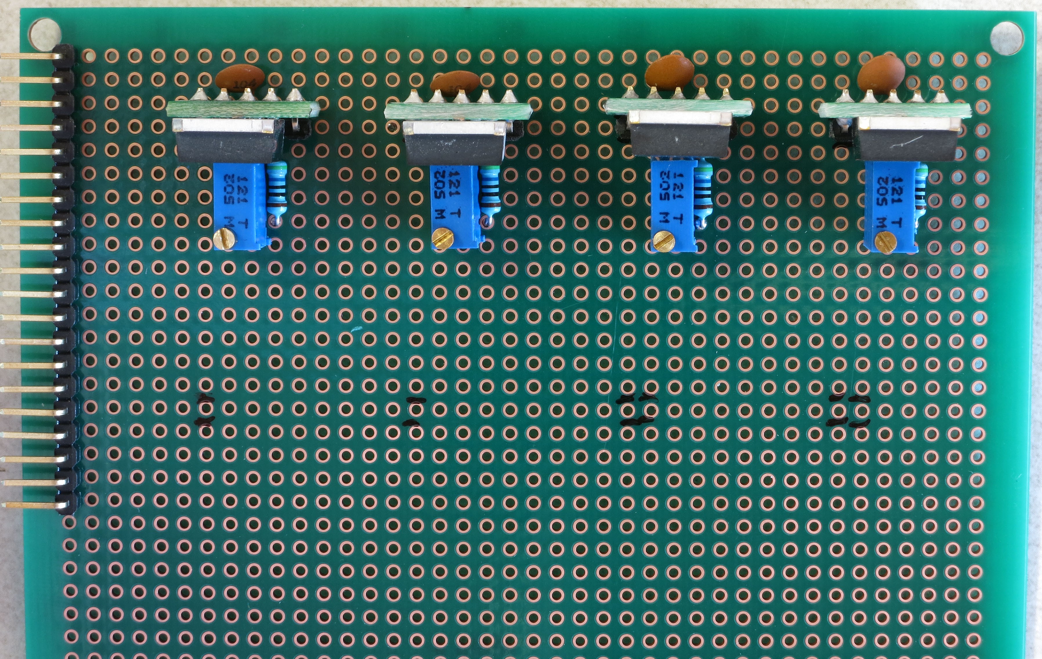
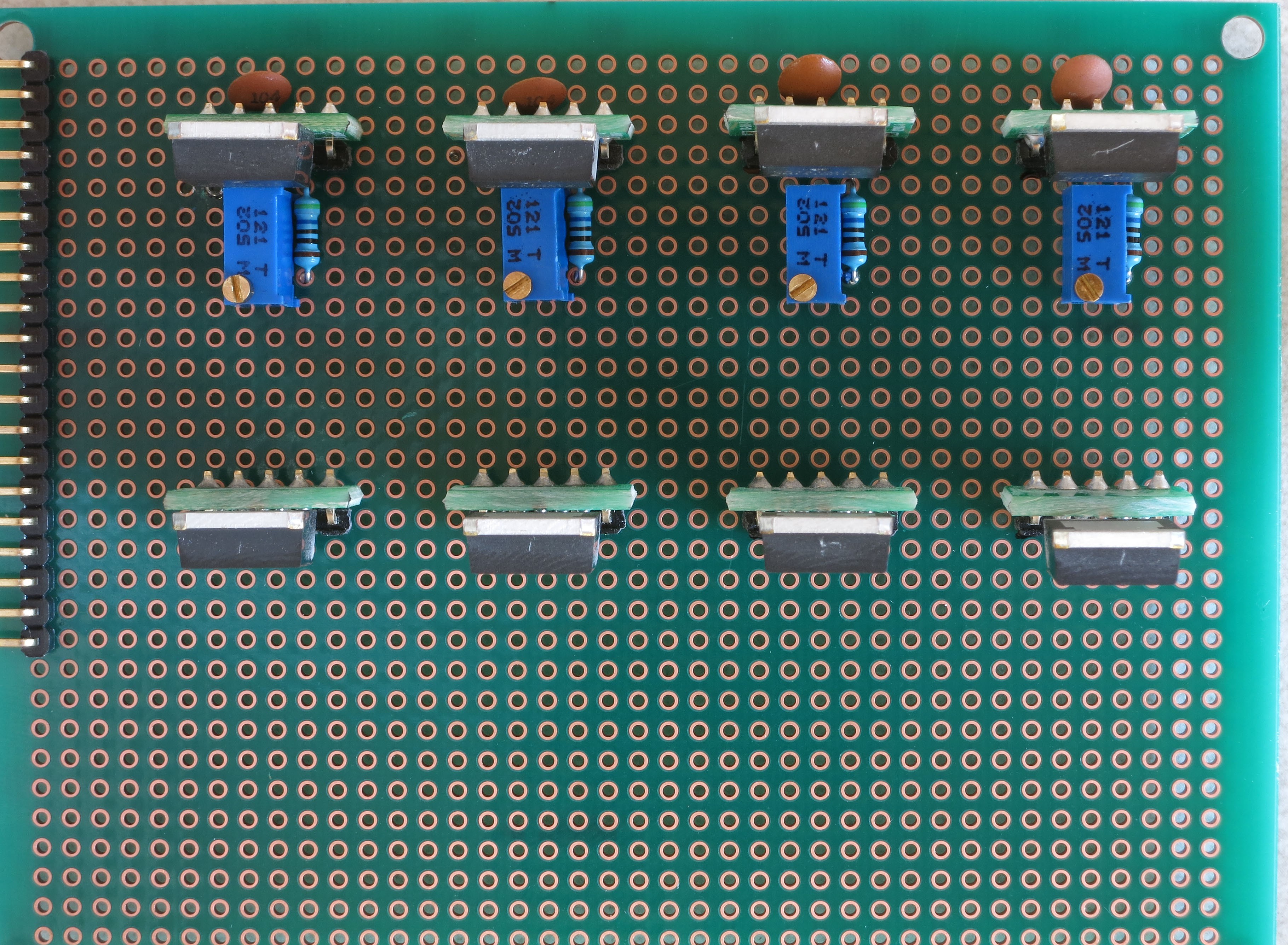
Then first install the capacitors, then the 560R and 5K variable resistors:
![]()
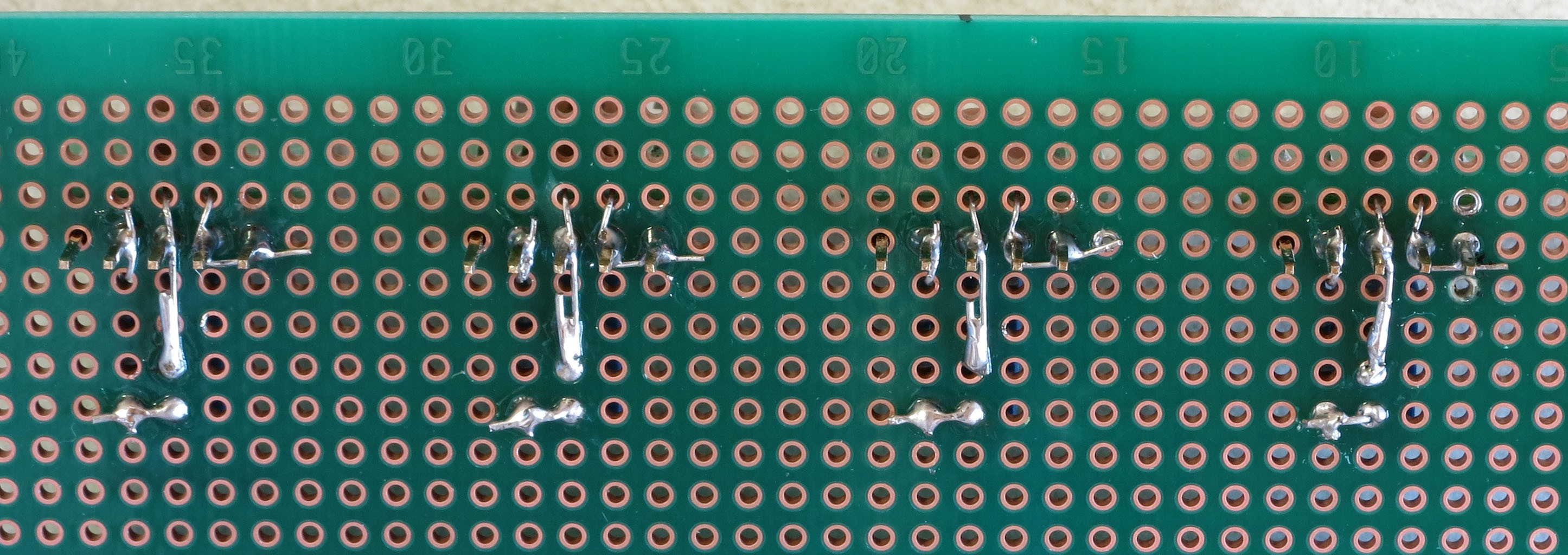
Which should look like this on the bottom:
Isn't that nice, neat and clean? Don't get used to it - you're about to mess it up with a bunch of wires. On the plus side, you have a lot more room to work with on this board than you had on the MOSFET driver shield, so the amount of cursing you'll do should be a lot less.![]()
-
13Step 13
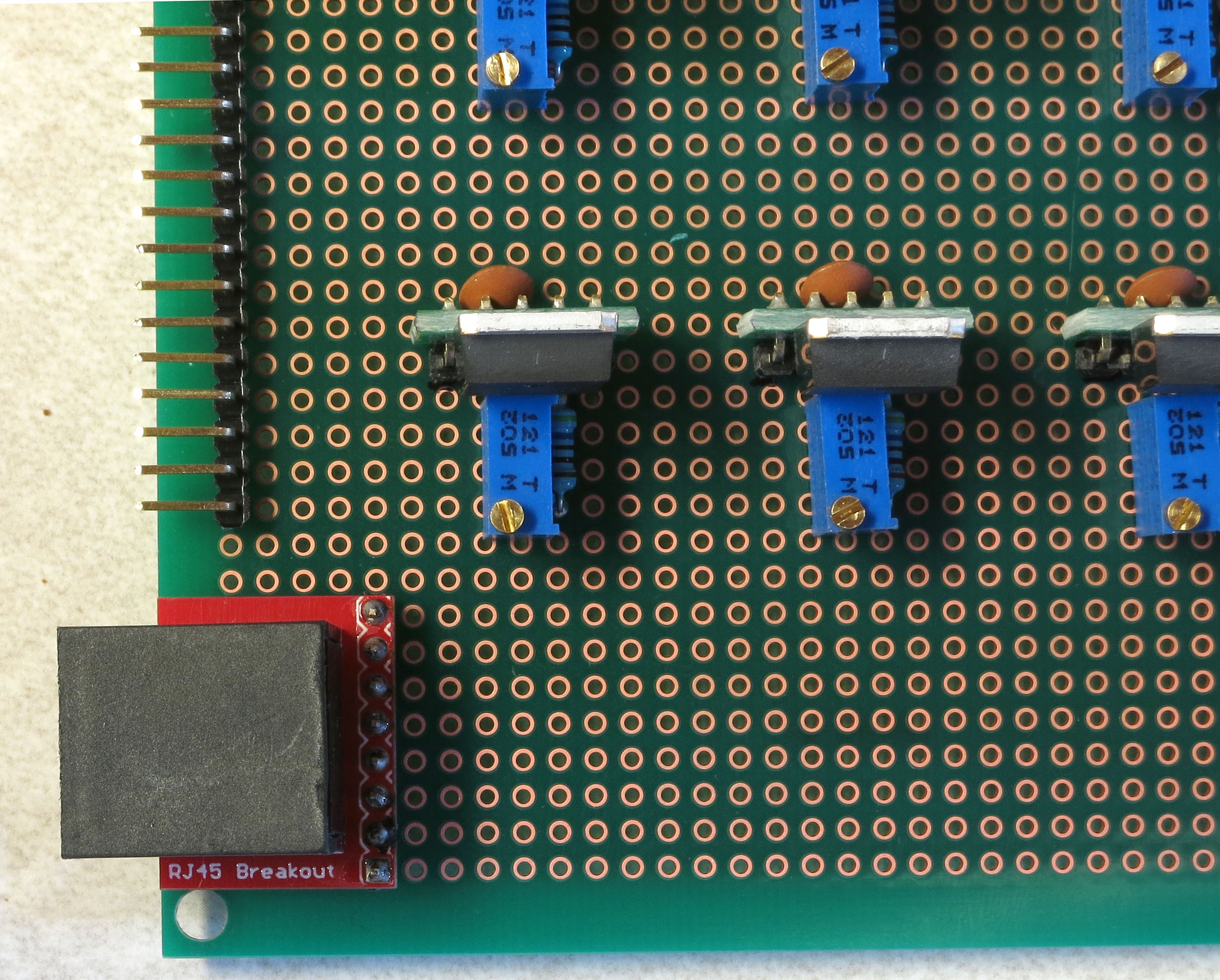
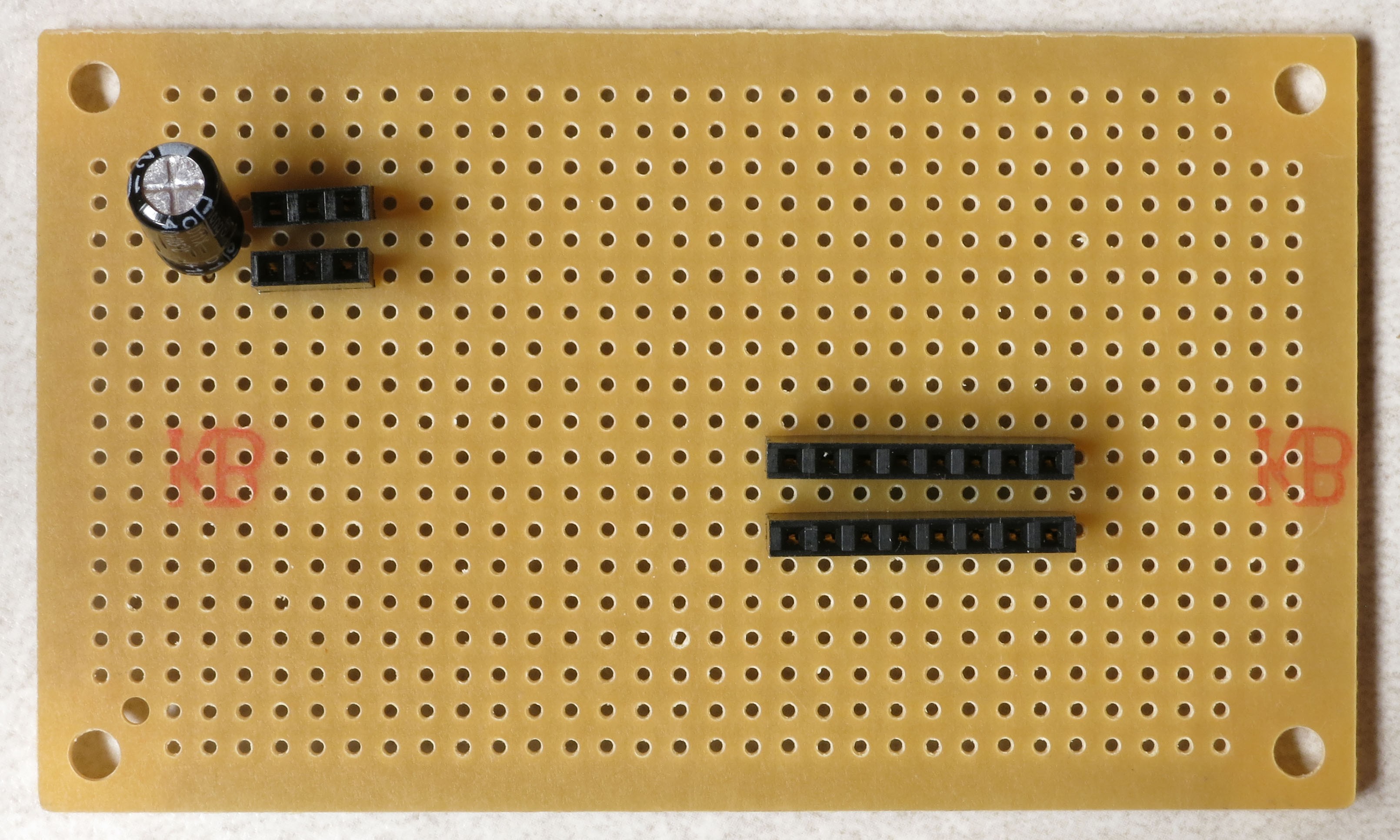
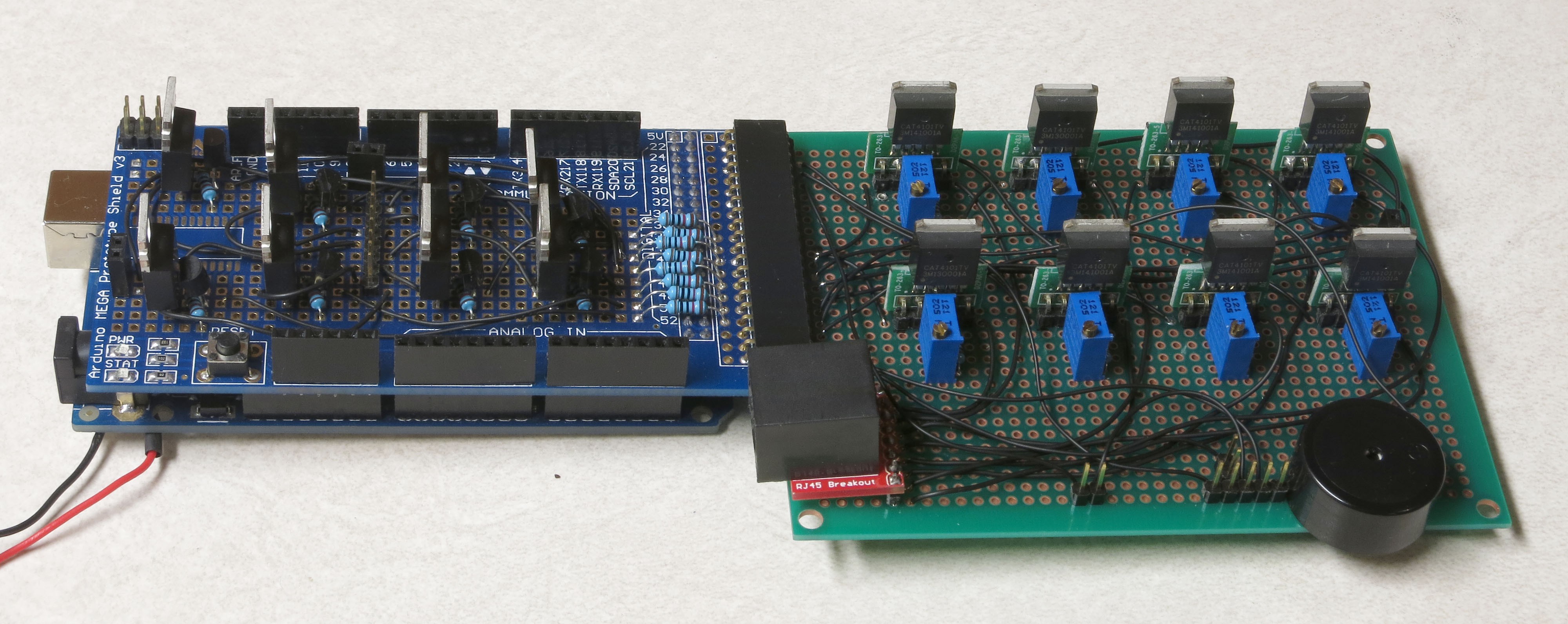
But before adding the wires, there are a few additional items that need to be soldered on the protoboard. First, the RJ-45 Ethernet jack on its breakout board:
![]() If you're using the protoboard recommended in the parts list, this is the correct position for it, all the way down in the lower-left-corner. Sliding the whole protoboard into the MOSFET shield board, it will just barely clear the edge of the board (and if it doesn't, a bit of filing should fix that):
If you're using the protoboard recommended in the parts list, this is the correct position for it, all the way down in the lower-left-corner. Sliding the whole protoboard into the MOSFET shield board, it will just barely clear the edge of the board (and if it doesn't, a bit of filing should fix that):![]()
If you use a protoboard of a different size, and in particular one that's smaller in the vertical dimension, you will probably have to re-orient the RJ-45 so that it faces downwards in order to make it fit. Not a big deal.
Unlike previous connections, where you want the connector to be flush with the board, for this connection you want the RJ-45 jack to tilt until the black knobs on the bottom touch the board:
![]() Solder it into place using the first and last pins.
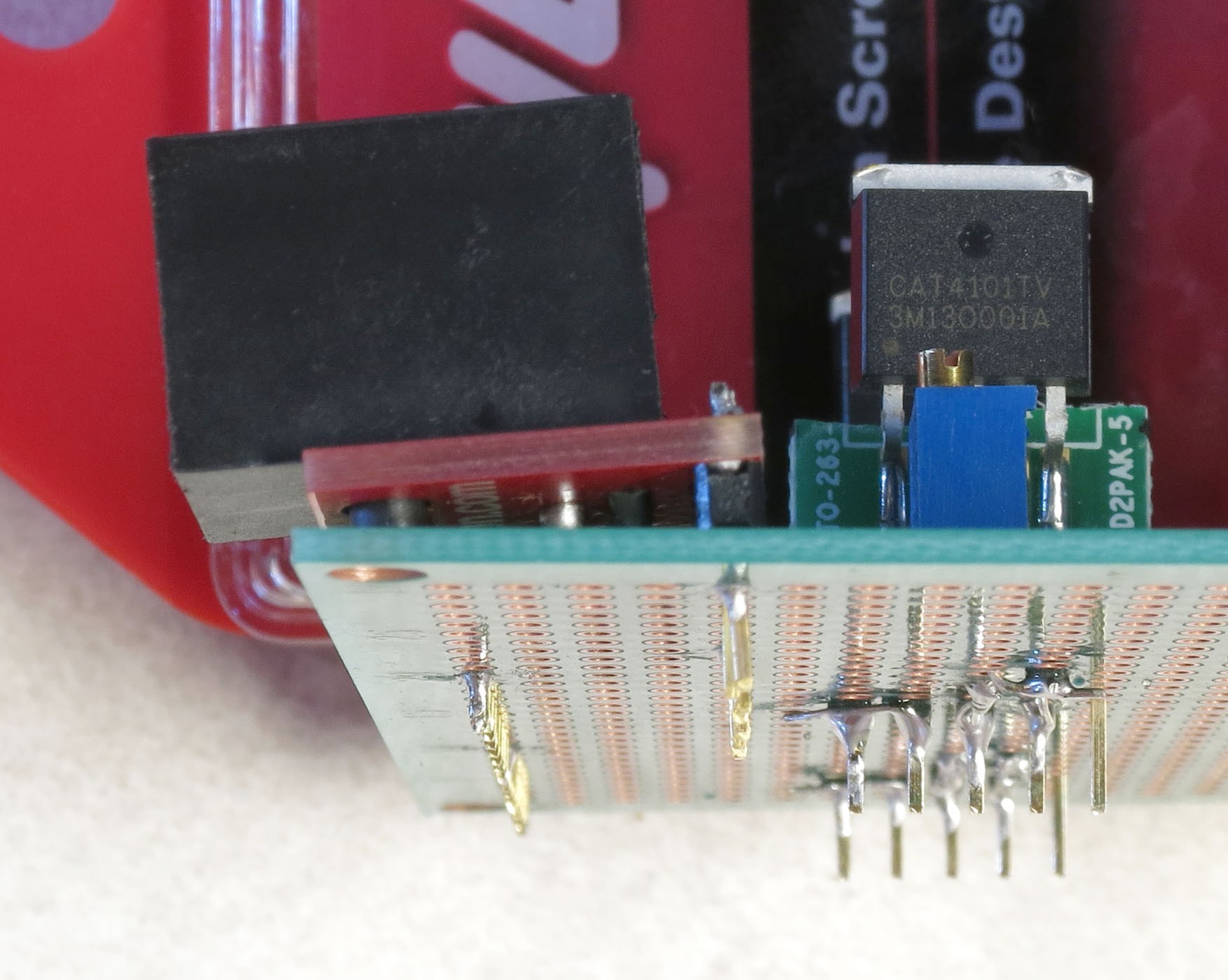
Solder it into place using the first and last pins.Next, put the buzzer in place on the board as shown below (+ on the right), and solder the two pins to hold it in place:
![]() Now break off a strip of 5 male header pins:
Now break off a strip of 5 male header pins:![]() And solder it next to the buzzer (1st and last pins):
And solder it next to the buzzer (1st and last pins):![]() It's a tight fit, but the 5-pin female header on the USB panel connector should still fit (or break out your file again):
It's a tight fit, but the 5-pin female header on the USB panel connector should still fit (or break out your file again):![]() Finally, you'll be soldering a 2-pin male header next to the 5-pin header you just did, and a two-pin female header on the middle right of the board, as shown here:
Finally, you'll be soldering a 2-pin male header next to the 5-pin header you just did, and a two-pin female header on the middle right of the board, as shown here:![]() For the male header, use a blob of solder to connect the pins on the 2-pin and 5-pin header that are next to each other. This 2-pin header is for a jumper that will optionally power a servo to fire the camera shutter for those cameras that don't support remotes. Make sure the solder only touches the adjacent pins, and no other:
For the male header, use a blob of solder to connect the pins on the 2-pin and 5-pin header that are next to each other. This 2-pin header is for a jumper that will optionally power a servo to fire the camera shutter for those cameras that don't support remotes. Make sure the solder only touches the adjacent pins, and no other:![]()
-
14Step 14
Next step is to wire up leads from the CAT4101s to the appropriate connectors. First, the LED connections that will ultimately connect to the ground (negative) lead on the LEDs, running along rows of the LED matrix (the rightmost CAT4101 connection in the schematic below, aka pin 5, LED in the figure below). Then, the connections from the Arduino to the CAT4101, that supply power and enable the CAT4101 (the two leftmost connections, pins 1 and 2, PWM and Vin in the figure below).
![]()
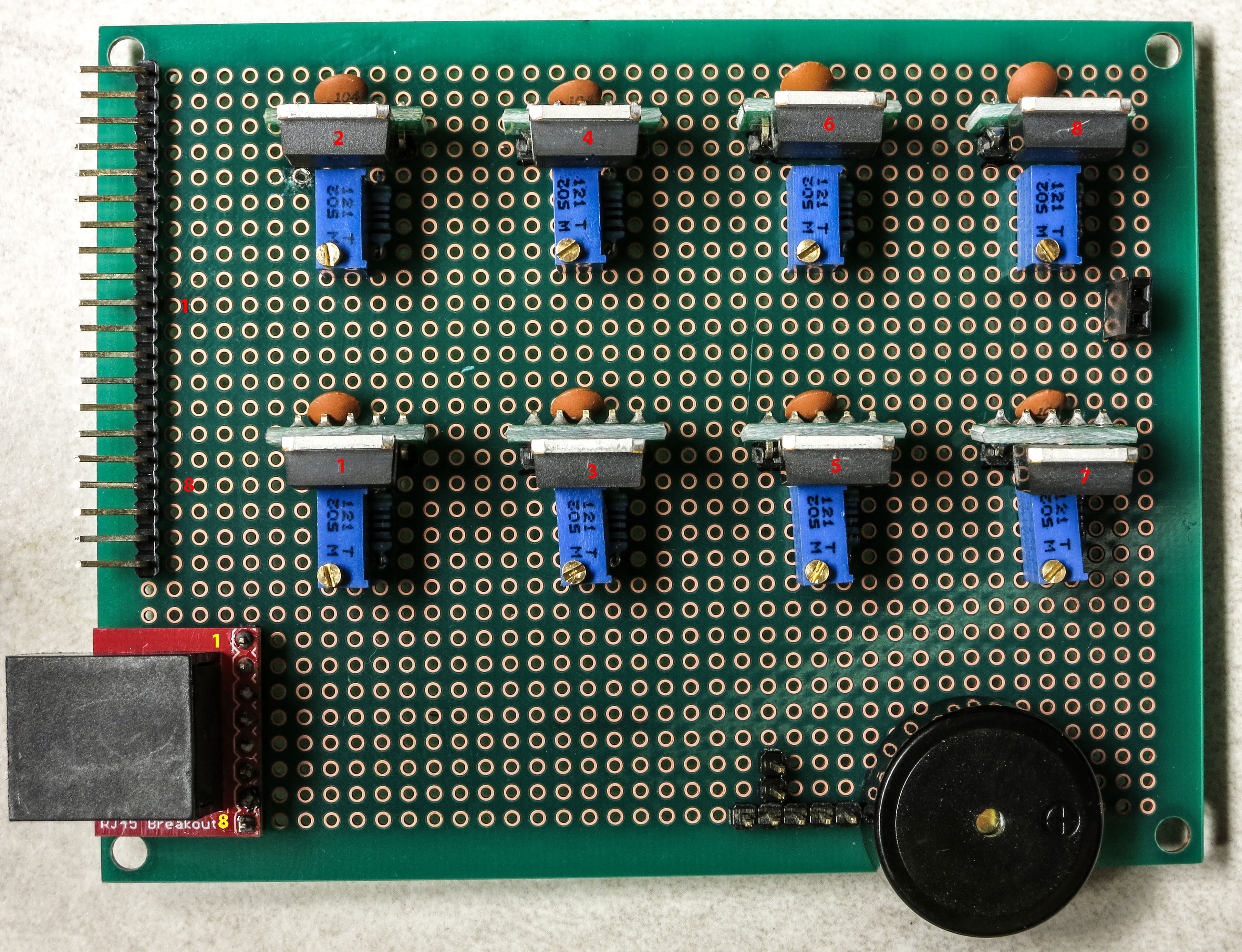
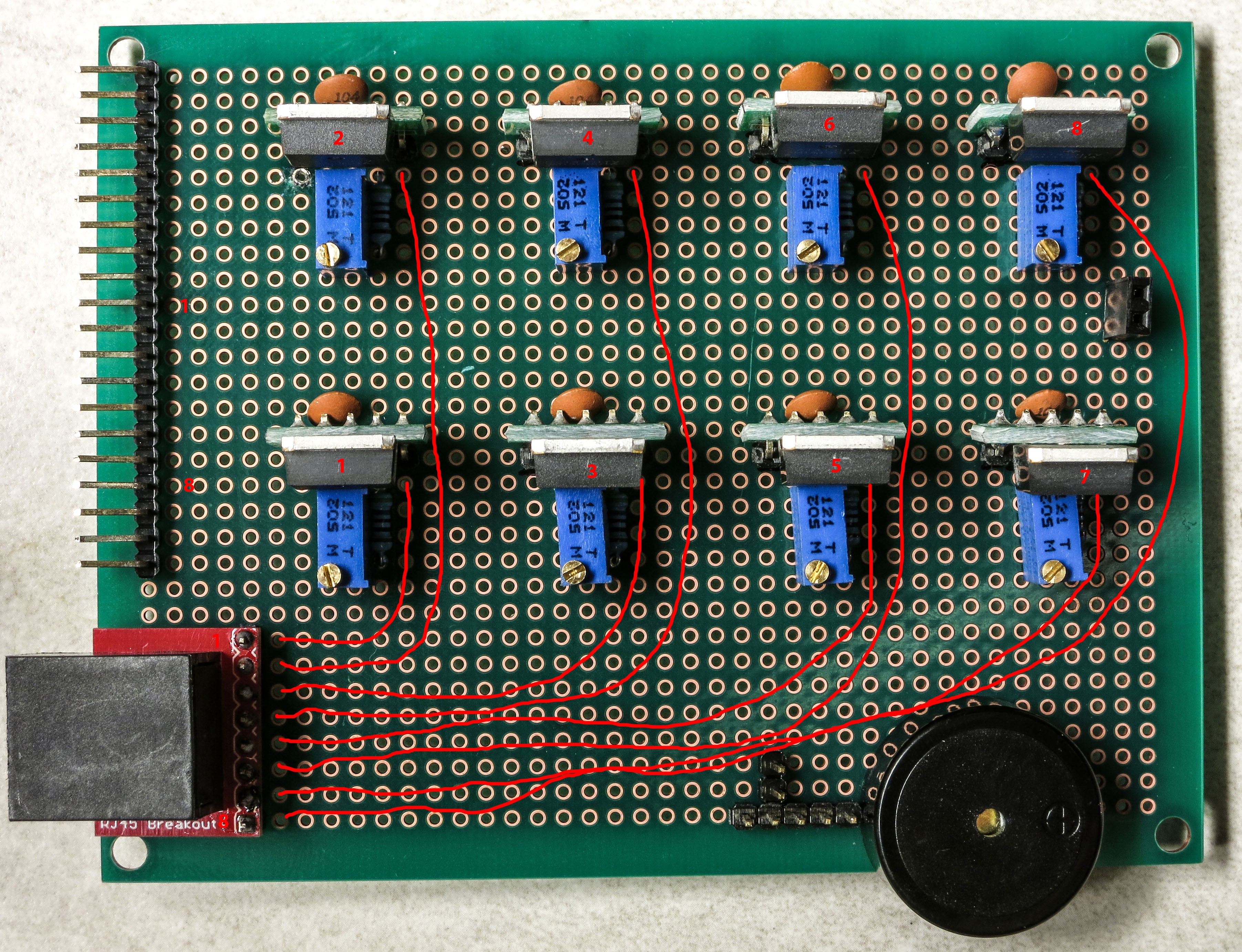
Each CAT4101 controls a separate row of the LED matrix, identified in the picture below with numbers 1-8 for the 8 maximum possible rows.
![]()
The connector on the left has the numbers 1 and 8 next to the positions where pins 1 and 2 on the 1 and 8 CAT4101s are wired to the corresponding Arduino outputs that power and enable the CAT4101s; the remaining connection numbers 2-7 are sequential between the 1 and the 8, of course. Similarly, the numbers 1 and 8 on the RJ-45 breakout board (lower left) are where you'll use the Kynar 24 AWG wire to link the pin 5 connection on the CAT4101 to the breakout board for the corresponding number, with the other pins corresponding to connections 2-7. I usually do the LED connection first - here's a schematic showing the wiring to be done between pin 5 and the RJ-45 breakout (in red):
![]() You don't have to follow the wiring path exactly - it only matters that the matching connections are soldered correctly. Here's how my board looks after that step:
You don't have to follow the wiring path exactly - it only matters that the matching connections are soldered correctly. Here's how my board looks after that step:![]() Next step is to electrically connect pins 1 and 2 on the CAT4101s to the corresponding pin on the protoboard connector on the left, which will receive control/power voltages from the Arduino. Since these were already shorted together when you installed the capacitors, you only need to solder the wire to pin 1. You can use the Kynar AWG 24 wire, but if you have thinner wire, you can use that as well, since this connection carries very little current (<20 mA). Here's the wiring schematic; I used a mix of red and white in drawing the wires to make it clearer, the color has no other significance:
Next step is to electrically connect pins 1 and 2 on the CAT4101s to the corresponding pin on the protoboard connector on the left, which will receive control/power voltages from the Arduino. Since these were already shorted together when you installed the capacitors, you only need to solder the wire to pin 1. You can use the Kynar AWG 24 wire, but if you have thinner wire, you can use that as well, since this connection carries very little current (<20 mA). Here's the wiring schematic; I used a mix of red and white in drawing the wires to make it clearer, the color has no other significance:![]()
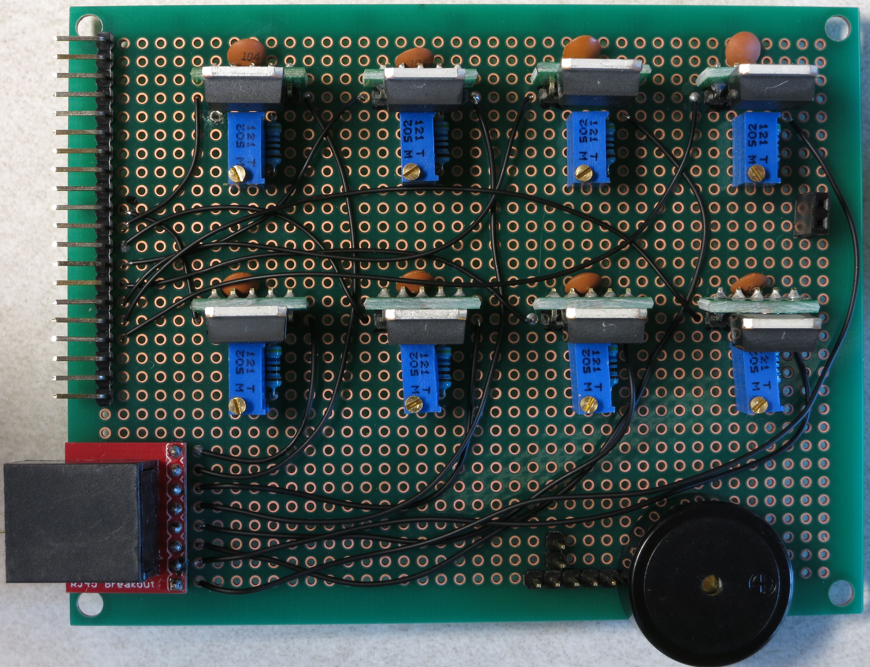
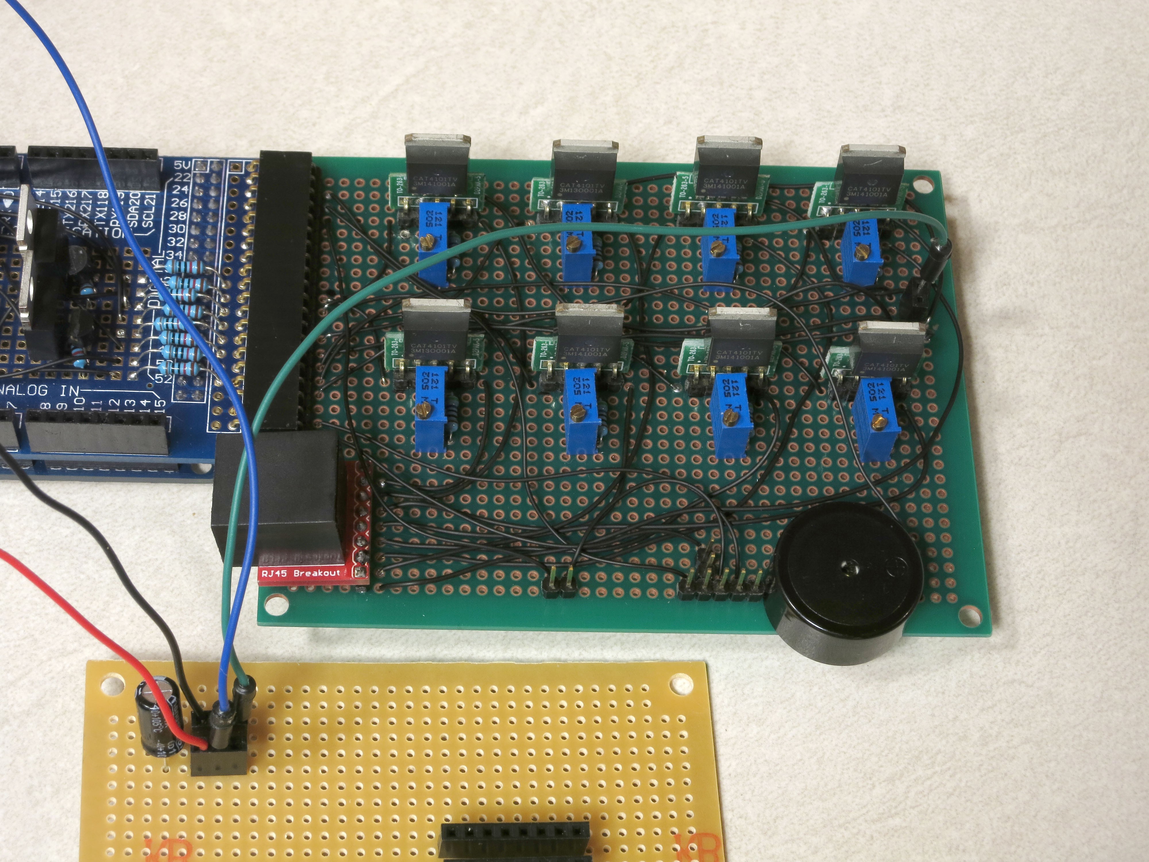
Once again, you don't have to copy the exact wire layout, you just have to make sure CAT4101 connection goes to the correctly numbered pin on the connector. Here's how mine looked after this step:
![]()
-
15Step 15
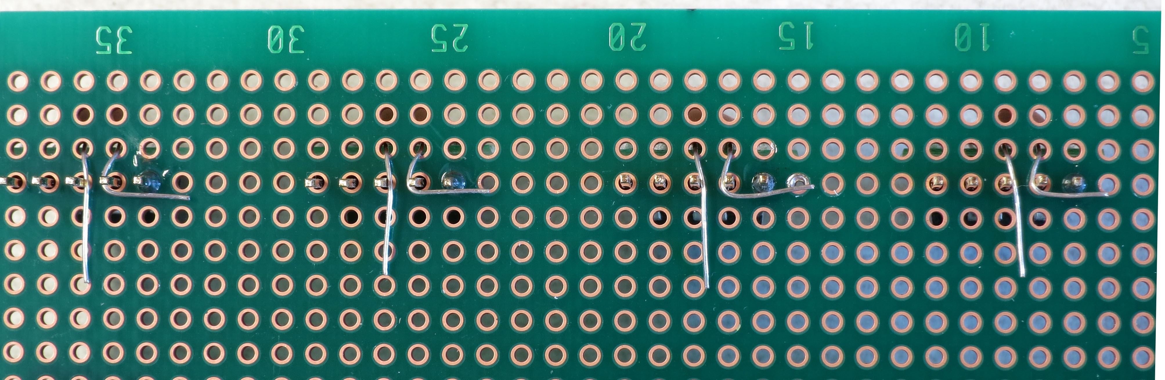
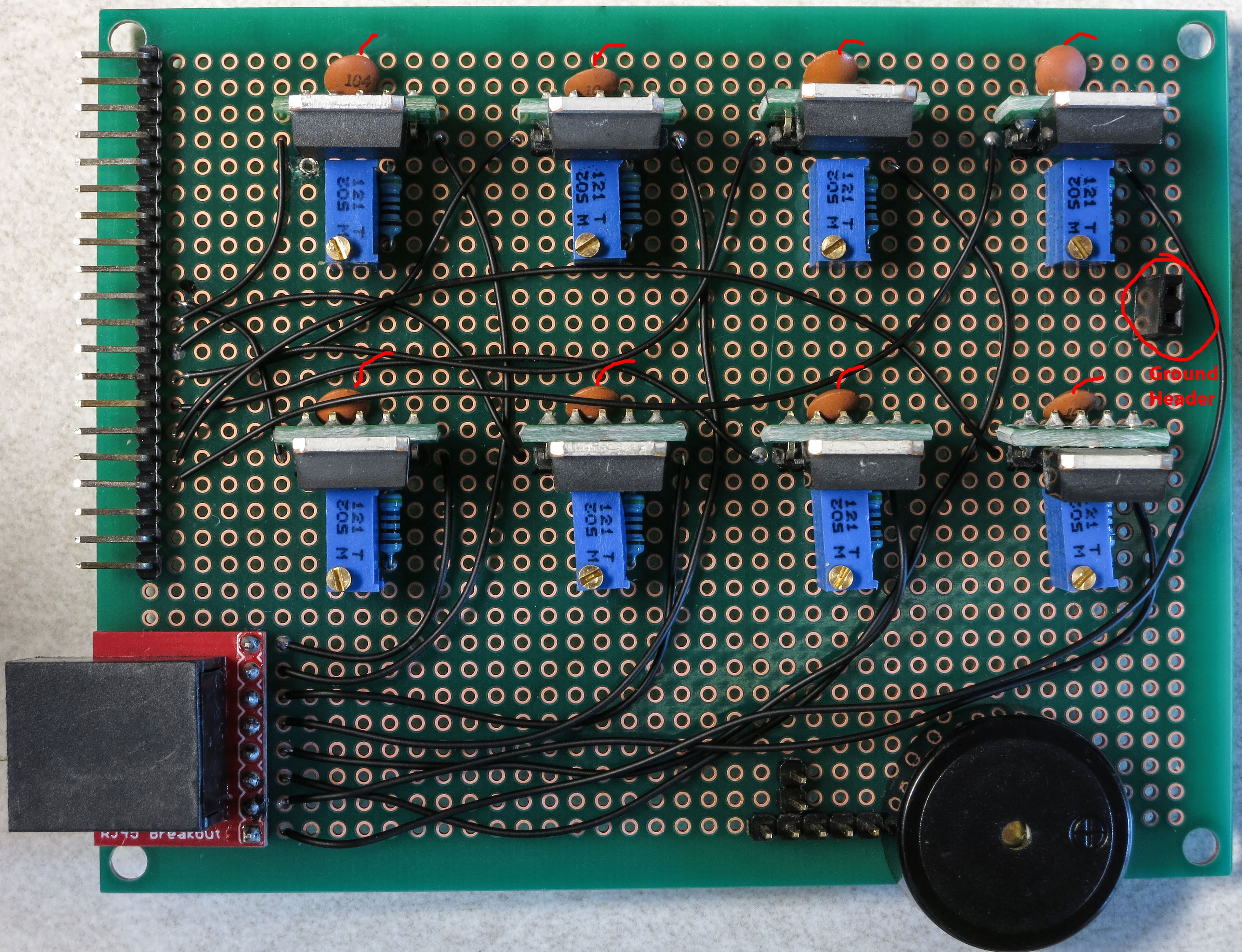
Time to finish wiring up the CAT4101 board. First step is to hook up the ground pins on all 8 CAT4101s to a common ground pin header on the right. Not going to draw all the wires here, as it's already too complicated. Plus, the exact layout of the wires doesn't matter - as long as the center pin of every CAT4101 gets connected to ground, the way the wire is laid out on the board doesn't matter. Here's a schematic showing where the ground wires should come off of the CAT4101s center pin, and where the ground two-pin female header on the right the wires should hook up to:
![]()
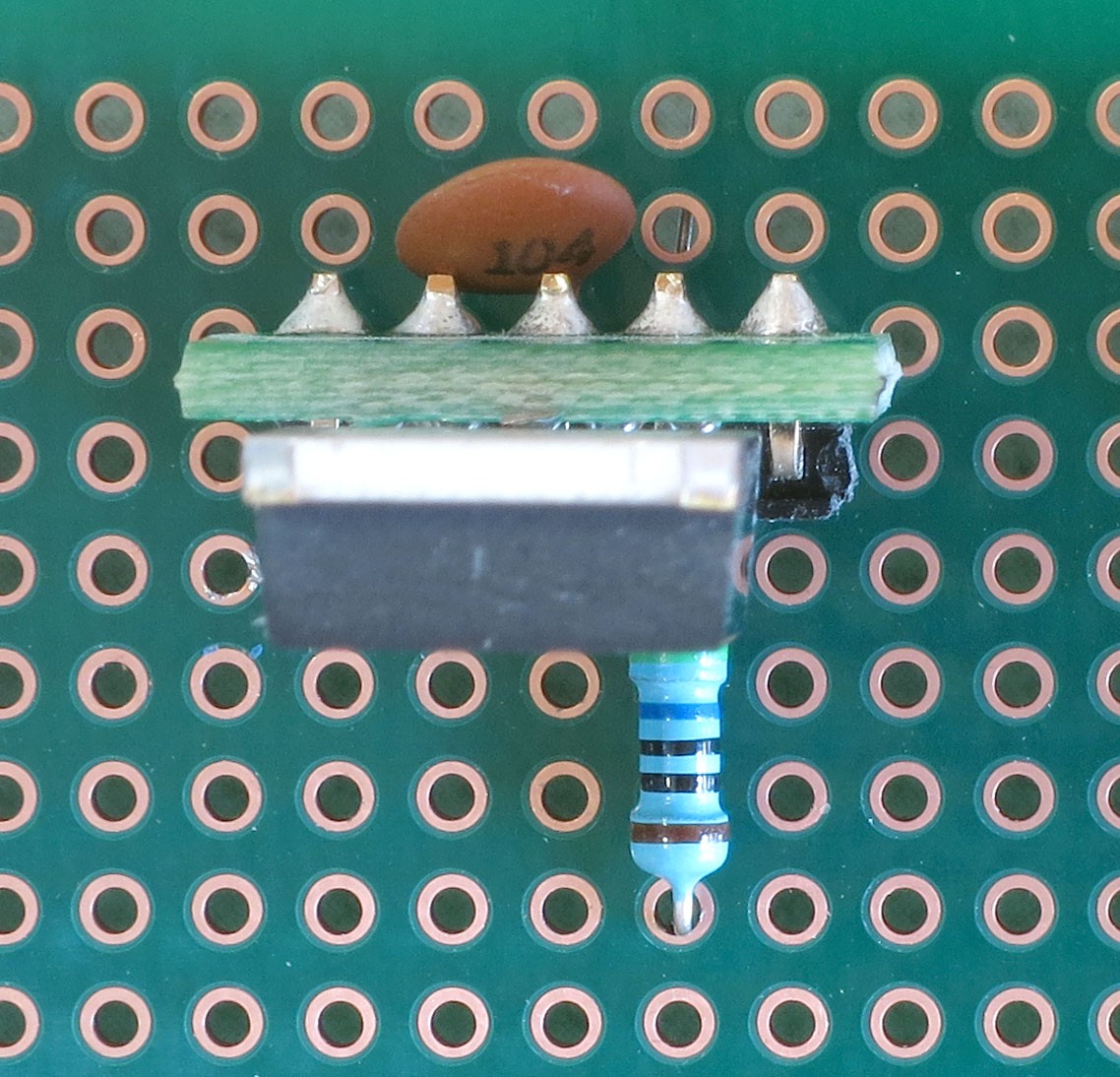
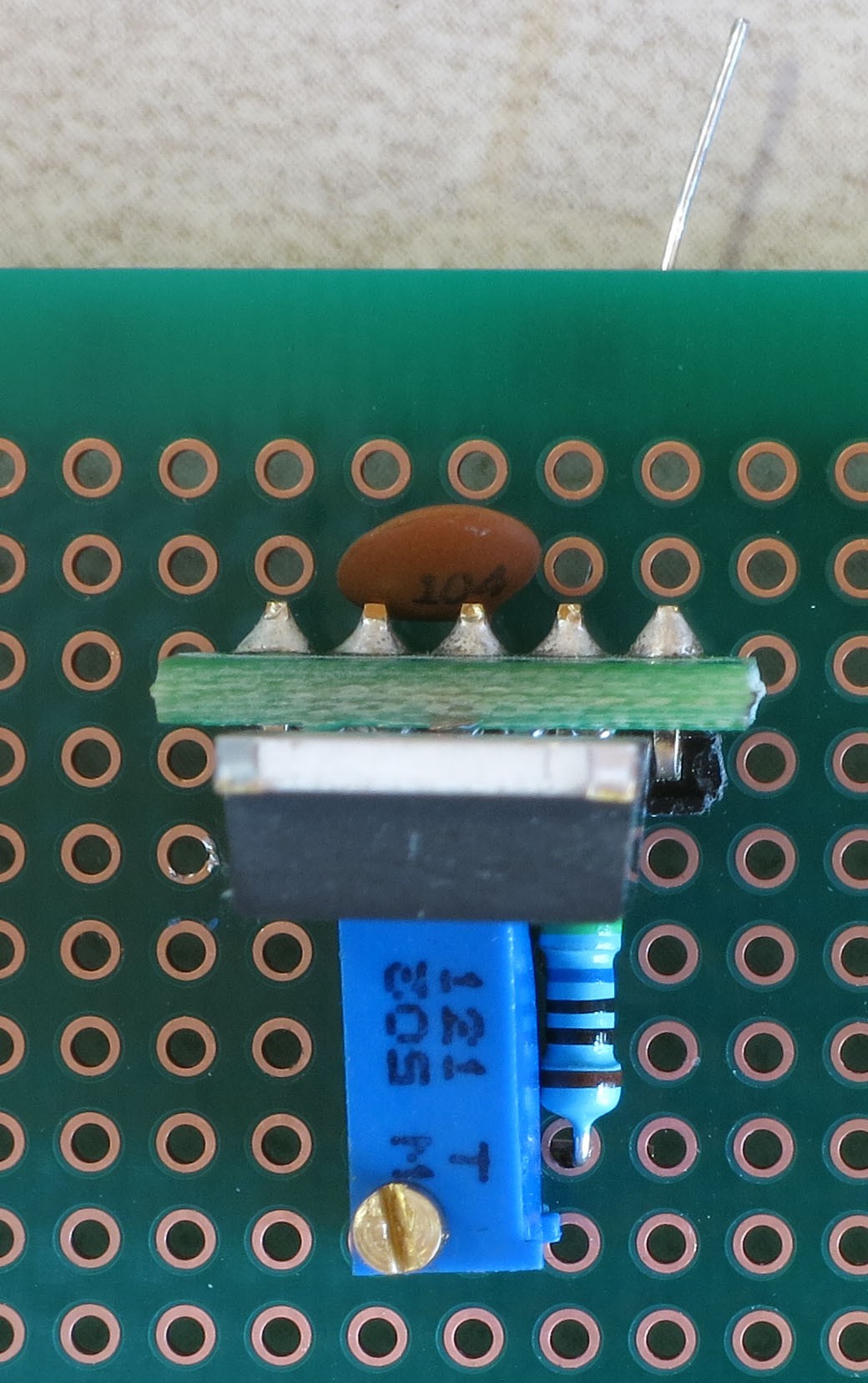
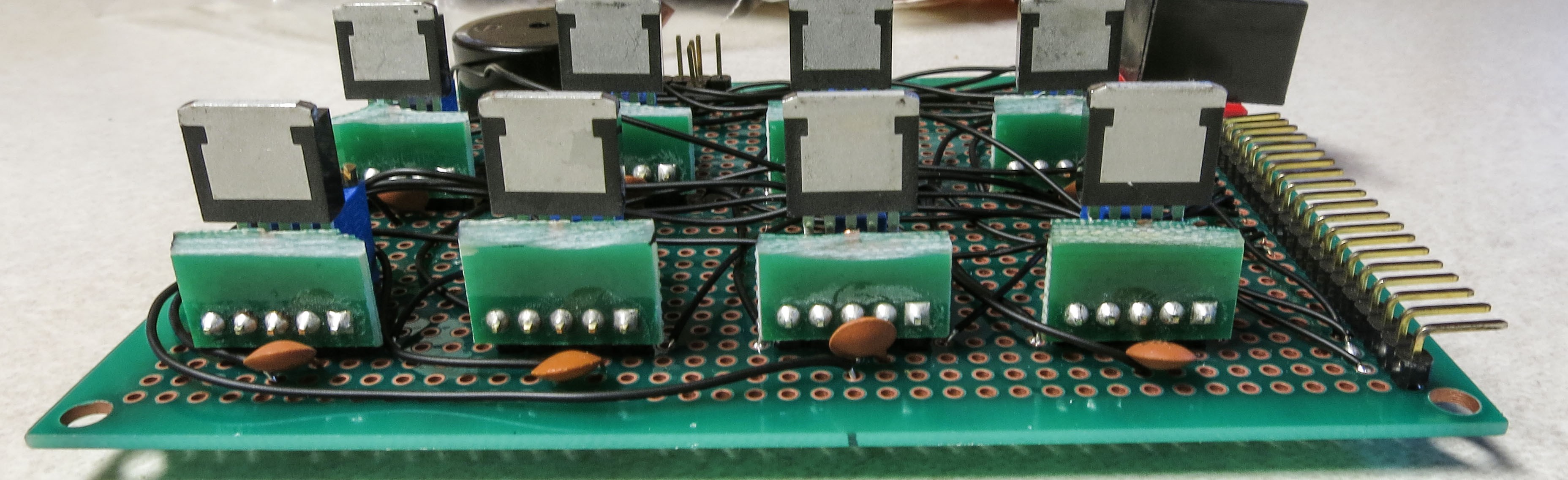
It's a bit difficult to see the exact connection spot, since the capacitors obscure it. So here's an side shot from the back, with the ground wires already soldered in place to the center CAT4101 pin (which is also already soldered to one of the two capacitor leads):
![]()
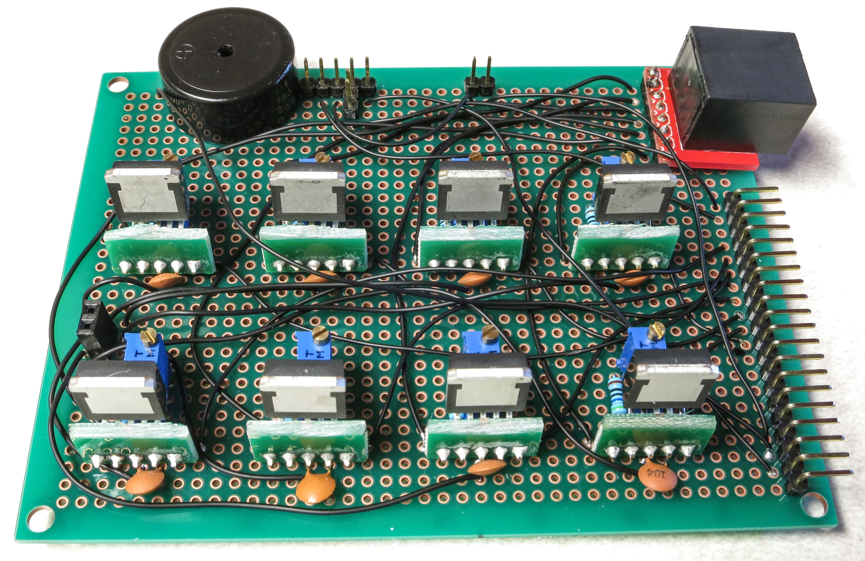
And here's an oblique view that shows the ground wire connections to all 8 CAT4101s:
![]()
Here's a view from the top, with all the ground wire connections in place:
![]()
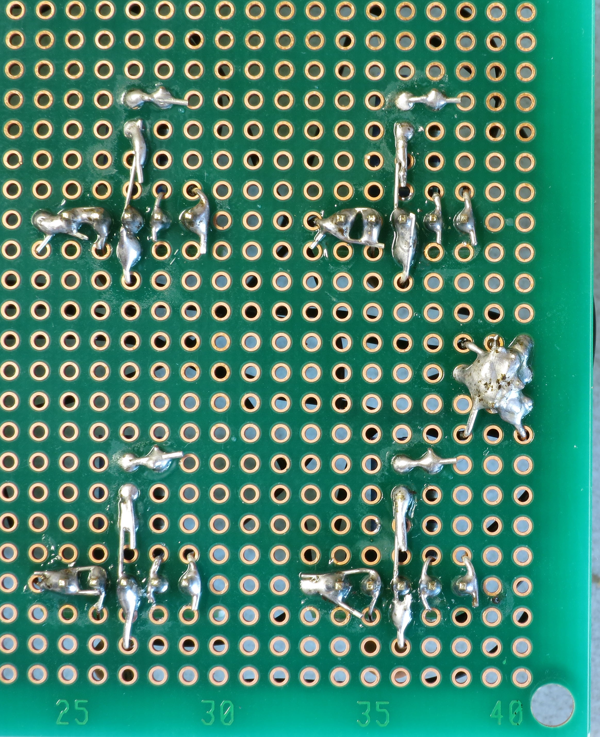
See how all the ground wires go to the two-pin female header on the right? Flip the board over, and the bare wire leads should all be bent over to overlay the header pins. Then use a lot of solder to make sure all the wire leads and pin headers are electrically connected; that's what the solder blob on the right below is:
![]()
Notice also how the wire lead from the ground wire connection is soldered to the center pin of the visible CAT4101s, and also to one of the capacitor leads.
You may be tempted to make this connection with shorter jumper wires between adjacent CAT4101 chips. Don't - it's specifically not recommended in one of the CAT4101 datasheets; they say that every ground connection should go independently to a single "star" ground that each CAT4101 connects individually to. I actually tried the jumper approach once, and ran into weird problems with LEDs turning on when they should be off.
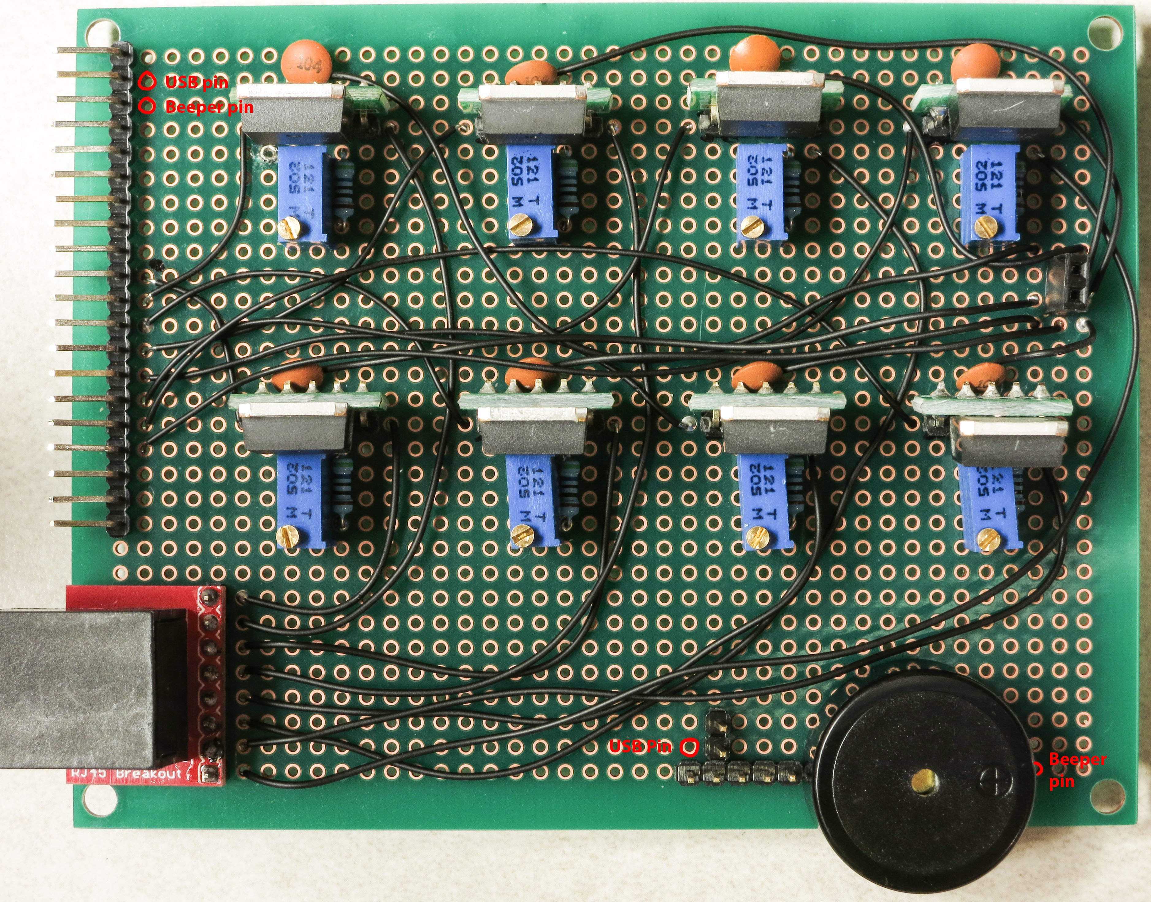
Next step is to wire up the USB control pin and beeper pin from the connector at upper left to the appropriate positions. The pic below shows where the connections should be made:
![]()
Here's how it looks on top after the wires have been connected:
![]() The 5V power supply for the servo shutter, and the ground connection for both the USB and beeper, need to be hooked up:
The 5V power supply for the servo shutter, and the ground connection for both the USB and beeper, need to be hooked up:![]()
The 5V connection is straightforward, it just gets soldered to the top pin of the two-pin female header:
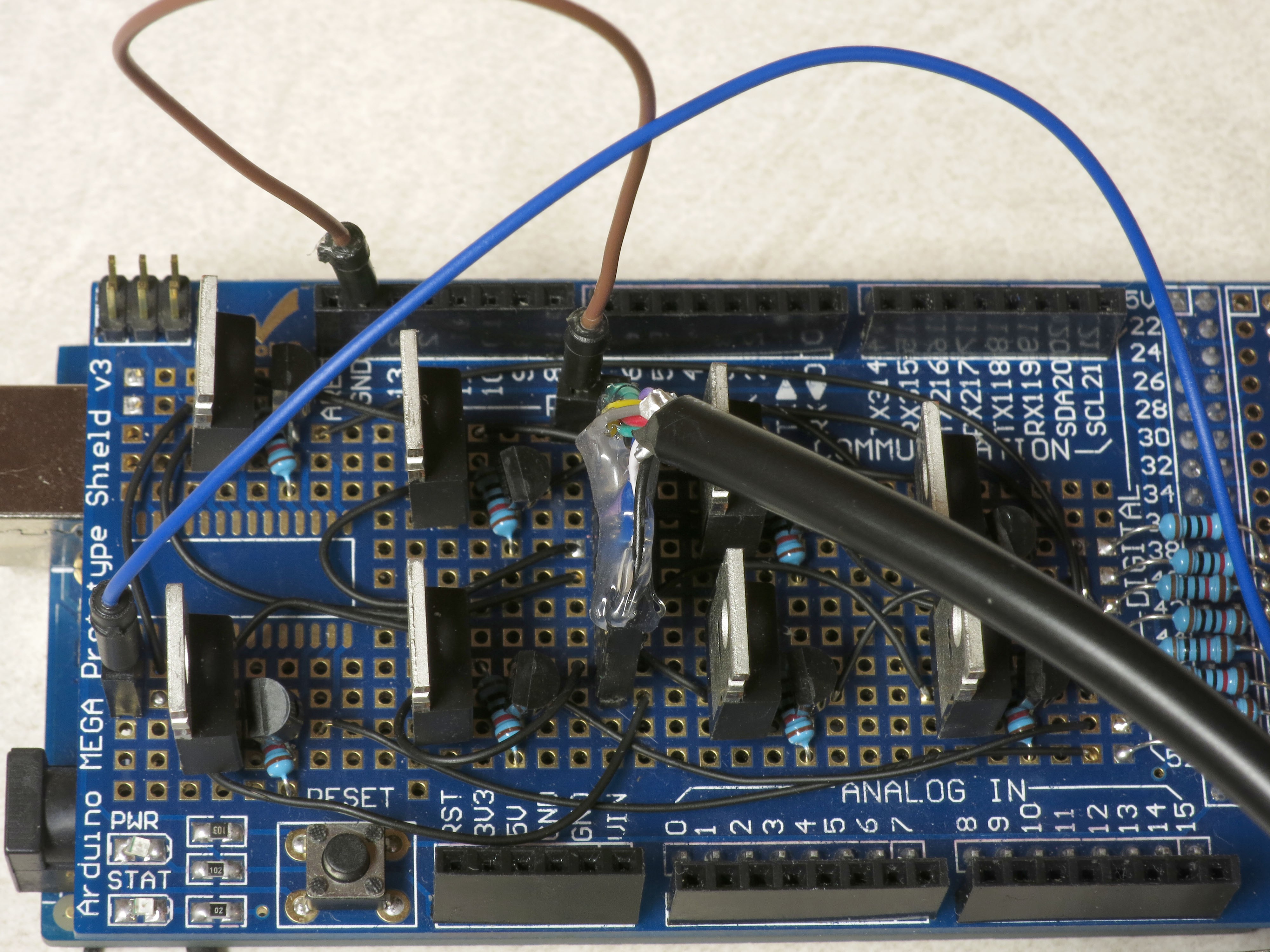
![]() The ground connection is a bit more complicated, since it needs to be connected to multiple pins. Trim the insulation a bit longer on the right end of the lead, and when you insert it in the specified position, bend it around that fourth pin on the 5-pin male header so that it touches the 5th pin on the header and heads over towards the beeper ground pin. Then bend the beeper ground pin over to make contact with the wire lead. It should look something like this:
The ground connection is a bit more complicated, since it needs to be connected to multiple pins. Trim the insulation a bit longer on the right end of the lead, and when you insert it in the specified position, bend it around that fourth pin on the 5-pin male header so that it touches the 5th pin on the header and heads over towards the beeper ground pin. Then bend the beeper ground pin over to make contact with the wire lead. It should look something like this:![]()
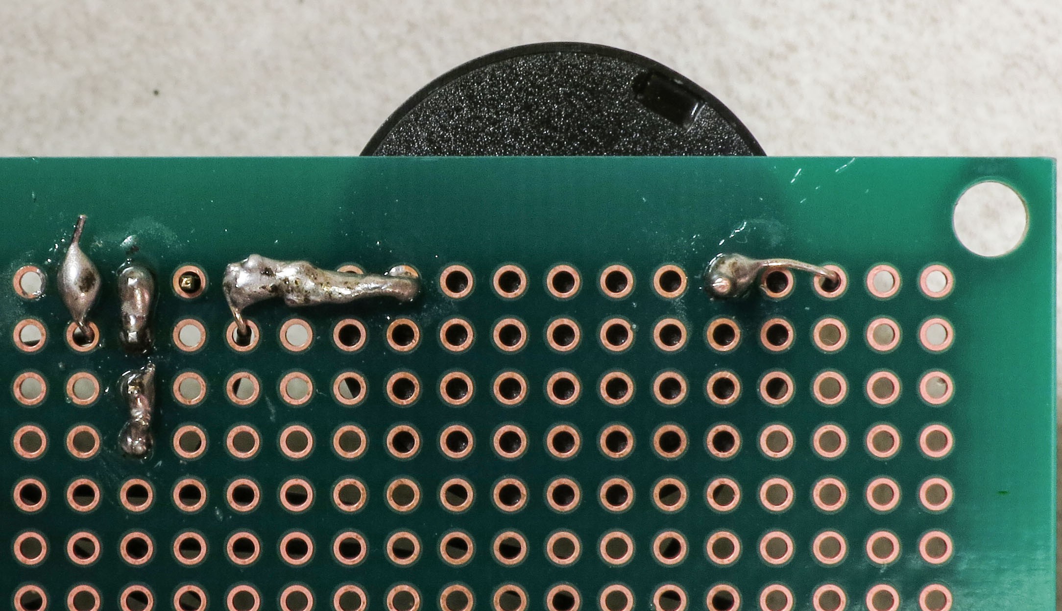
Now lay the solder on thick so that all those pins and the wire are electrically connected:
![]() Check that all the pins/wires are soldered as you see above. On the top side, the board should now look like this:
Check that all the pins/wires are soldered as you see above. On the top side, the board should now look like this:![]()
Originally, the board was done at this point. However, since I decided to add a servo shutter system to operate cameras that don't have a remote capability, I decided to add an additional electrical connection to the 5-pin male header that the USB panel connector will be hooked up to. And I wanted the option to be able to disconnect this if I didn't need it, to remove the possibility of problems or damage to cameras with misapplied voltages. So I added a two-pin male header to the bottom, soldered a wire connection from the connector at upper left to the left pin, and a wire connection from the right pin to the one remaining unsoldered pin on the 5-pin male header. Here's what it looks like; the drawn red traces parallel the actual wire connections:
![]()
And here's what it looks like without those red traces, and all the wiring done:
![]()
Double-check all the wires you see here to make sure your board has a corresponding connection. If they all check out, you're done with this board, and with the most difficult wiring of the entire project. Yay!
One more step, which I don’t have a picture of. The Ethernet jack in the lower left-hand corner is held on only by the 8 soldered pins. That’s reasonably strong, but it could use some reinforcement. Take some adhesive, and fill in the gap between the red Ethernet PCB board and the green PCB board. Thick stuff you can stick into the crack is best; take care not to block the Ethernet jack. I used Plastiweld, but hot glue or silicone adhesive would be reasonable alternatives.
-
16Step 16
The Arduino Mega is designed to supply up to 500 mA of current from the +5V connection when running from a USB connection. That's not enough to power the 1A LEDs on the RTI system, so a separate power supply (8-12V) capable of supplying up to 2A of current is specified (2A because I've had problems with noise from power supplies that are only spec'ed for 1A). While there's a Vin header on the Arduino board that supplies full voltage from the power supply, I don't know if it shares the 500 mA current limit as well. So I decided to power the LEDs directly from the 8-12V power supply, bypassing the Arduino completely.
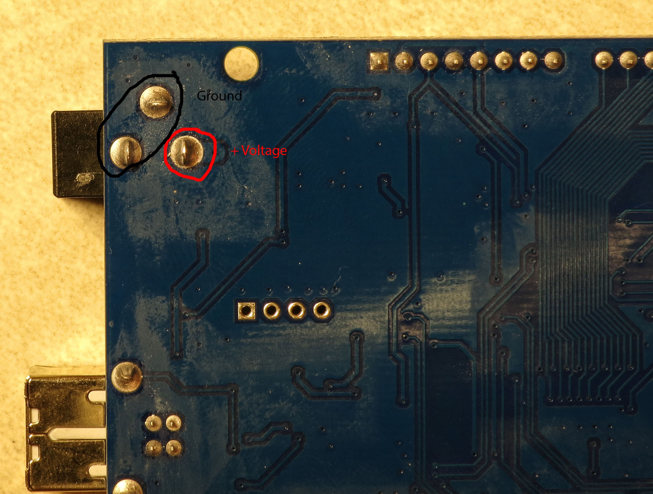
On the bottom of the Arduino Mega, near the power supply jack, are three solder connections to the power jack. Two connect to the power supply ground, while the third connects to the power supply positive voltage (8-12V):
![]()
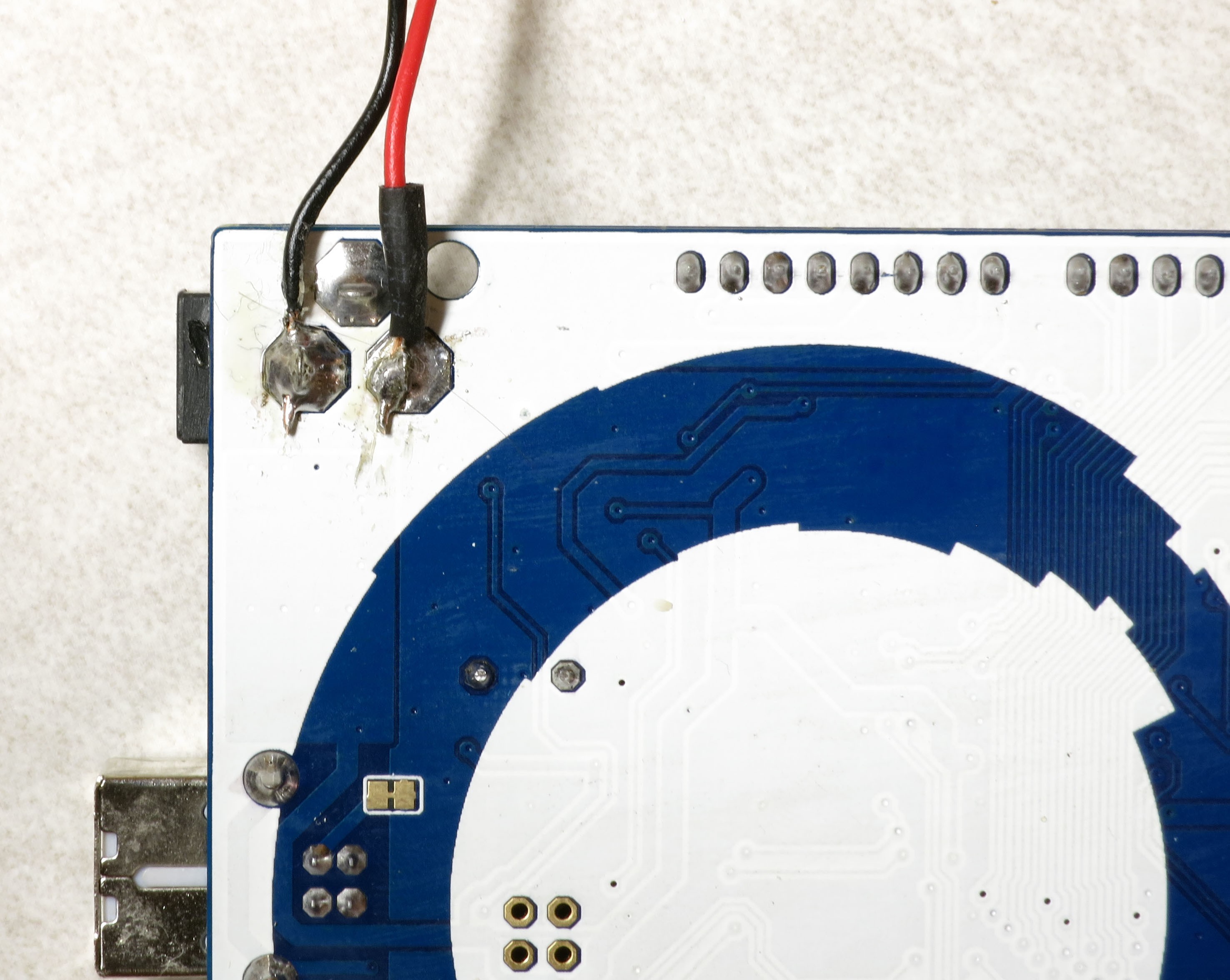
You will need to solder 22 AWG wires to both the positive voltage connection and one of the two ground connections; cut two pieces of wire about 4" (10 cm) in length, and strip the insulation of both ends of each piece of wire. The usual convention is that positive voltage is indicated by a red wire, while ground is a black wire. There are large blobs of solder on the connections, so it may take a while to get the solder to melt. Use a large soldering iron or gun if you have one, otherwise either use a chisel tip on your soldering iron for maximum heat conduction or wait a long time using a regular point tip for the solder to melt. Then press the bare wire lead into the melted solder blob and let it cool; if necessary, add more solder to cover. It should look something like this:
![]()
I used a small piece of heat shrink tubing on the red wire to make sure it wouldn't short out against the ground connections.
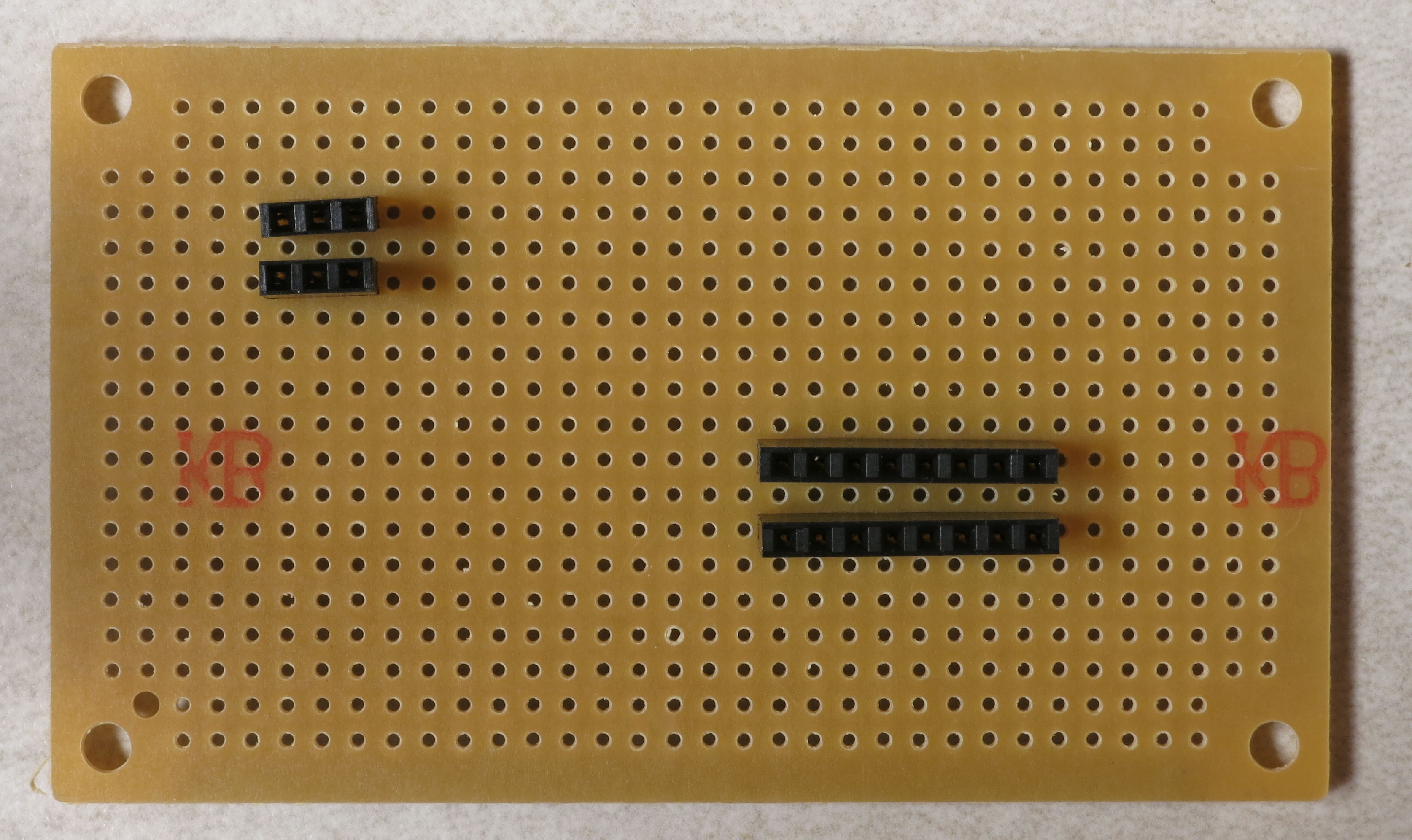
There are going to be a fair number of connections required to both the +8-12V/GND connections directly from the power supply, and also the +5V/GND connections from the Arduino board; for the latter, more connections than are actually available on the Arduino. To solve this pin connection shortage, you will need to solder two 3-pin female headers to a strip protoboard for the high voltage supply and ground, and two 5-pin female headers for the Arduino +5V and GND connections:
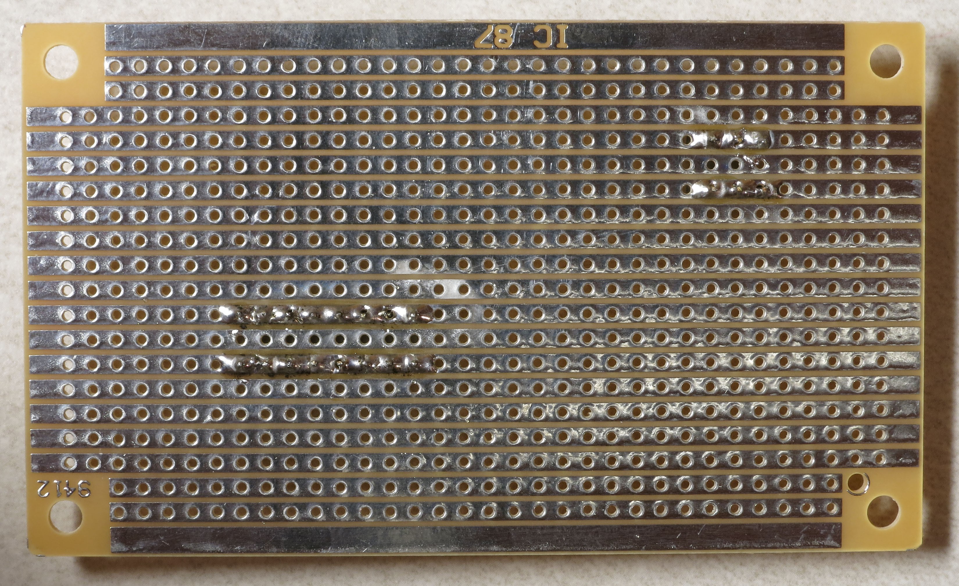
![]() If you flip this strip protoboard over, you'll see that instead of every hole being independent of each other as on a plain protoboard, holes in a single row are electrically connected to each other with a metal strip. So if you solder every header pin to that metal strip, as in this picture, all the sockets in each individual female pin header will be electrically connected to each other:
If you flip this strip protoboard over, you'll see that instead of every hole being independent of each other as on a plain protoboard, holes in a single row are electrically connected to each other with a metal strip. So if you solder every header pin to that metal strip, as in this picture, all the sockets in each individual female pin header will be electrically connected to each other:![]() Finally, although the +8-12V power supply should produce a fairly clean and non-noisy voltage, I added a 100 uF electrolytic capacitor across the 3-pin headers to play it safe and smooth out any residual noise. The capacitor is soldered to the strips so that the side with the white indicator goes on top, as seen in this picture:
Finally, although the +8-12V power supply should produce a fairly clean and non-noisy voltage, I added a 100 uF electrolytic capacitor across the 3-pin headers to play it safe and smooth out any residual noise. The capacitor is soldered to the strips so that the side with the white indicator goes on top, as seen in this picture:![]()
That white capacitor indicator goes to the ground side, and that's the header side where you will plug in the black ground wire from the Arduino; the + voltage red wire will plug into the other header. That will leave the other two female header sockets on this strip free to supply power and ground to the LEDs, and also to power an LED that indicates when the power supply is plugged in. No capacitor is need for the 5-pin headers, since it receives voltage that's already been filtered by the Arduino.
You now have the ability to power up the system to turn on the high-power LEDs. But to test both the system and the LEDs, connection wires will need to be soldered to the LEDs so that they can be hooked up to the system. That's the next step.
-
17Step 17
Time to get the LEDs ready for installation in the dome.
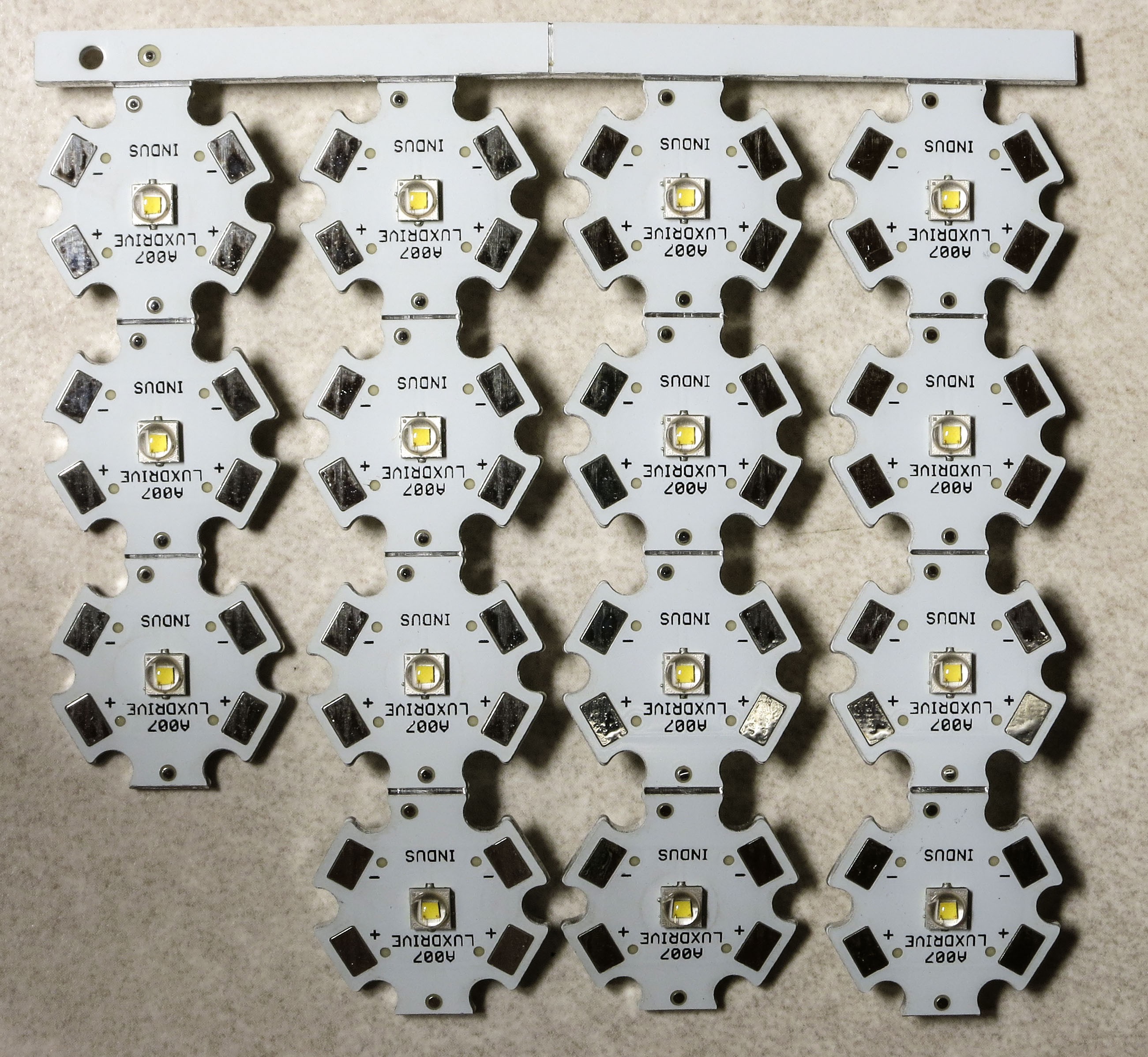
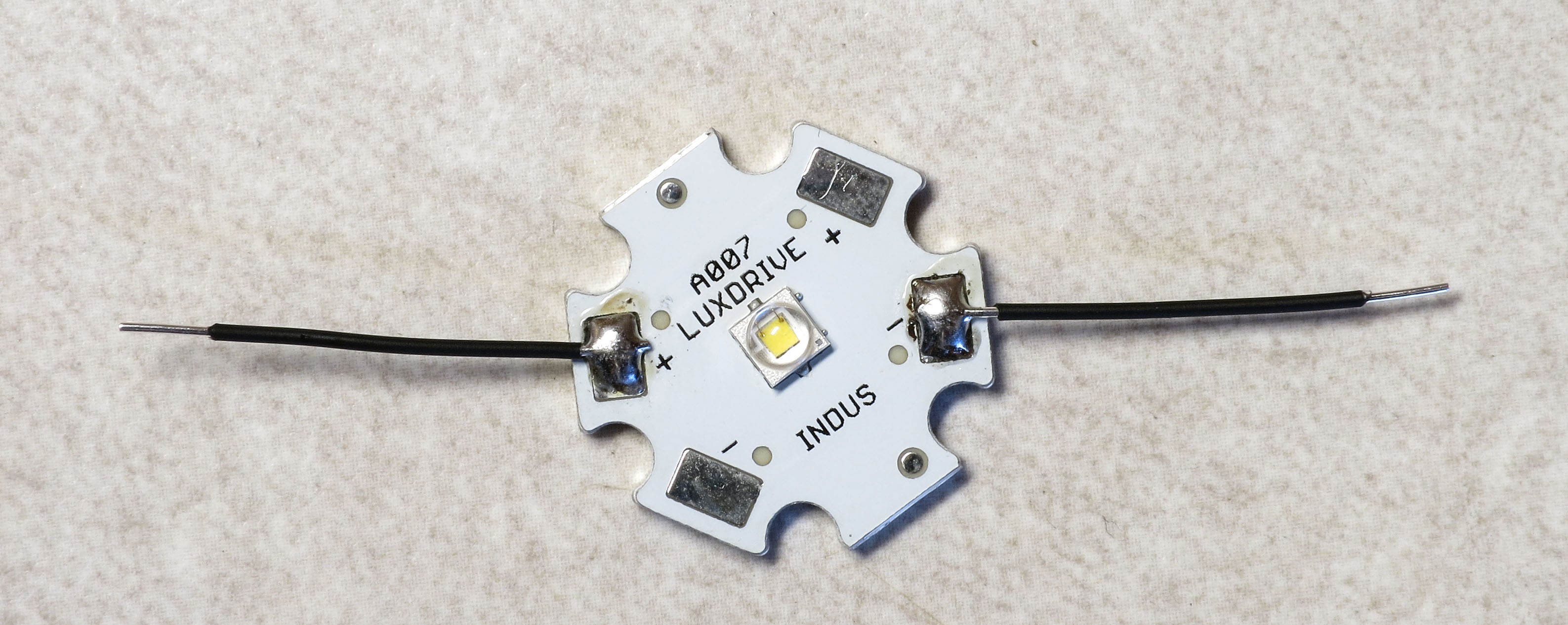
When you receive your 3W LEDs in standard star packages, they'll like show up attached together, like this:
![]()
Just bend them back and forth along the scores until they detach from the metal strip and each other.
![]()
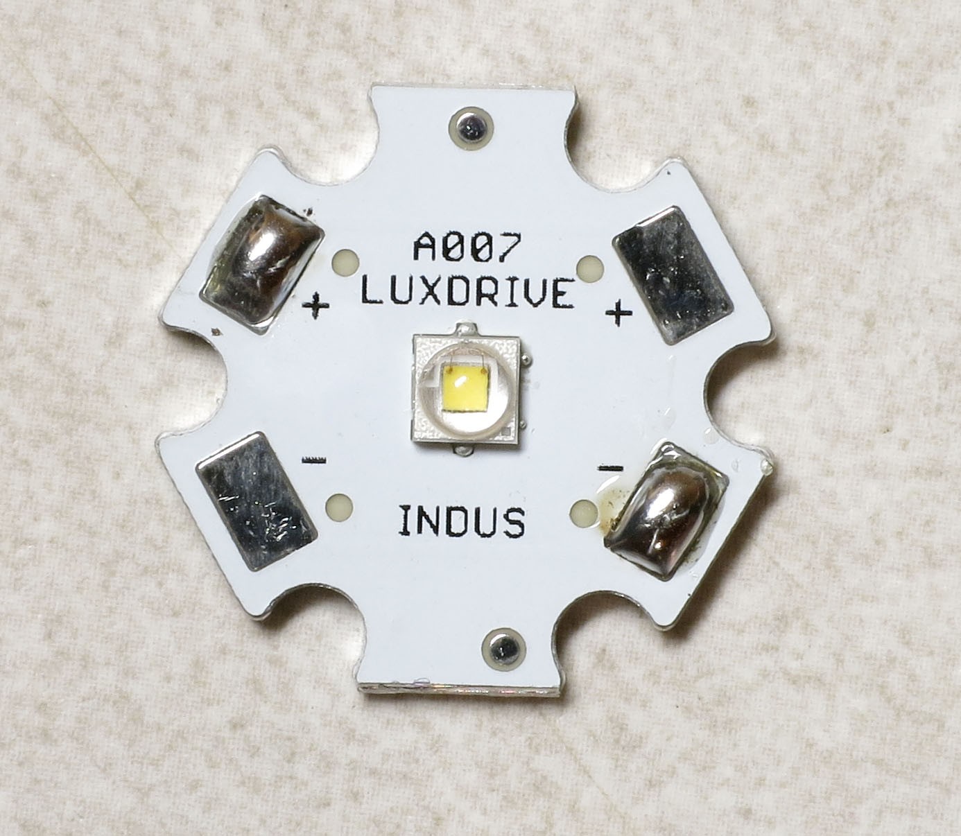
You're going to be soldering wires to one of the plus and one of the minus pads. There's a guide to soldering these star LEDs at LEDSupply.com, along with a YouTube video demonstrating the technique.
But I'm recommending a few changes from their approach for the LEDs for the RTI system:
1. Solder wires to opposite pads, not adjacent ones.
2. Don't tin the wires - in this case, they're so thin that it's not effective.
3. If you have one, use a chisel tip on your soldering iron.
4. When heated, lay the chisel tip against one of the pads so that the flat part is roughly perpendicular to the surface of the LED pad. Then apply the solder wire to the place where the flat part of the chisel tip and the LED pad touch. The solder should melt and flow smoothly across the pad to create a nice blob across the pad. Repeat on the other pad, then repeat for every single LED you have.
![]()
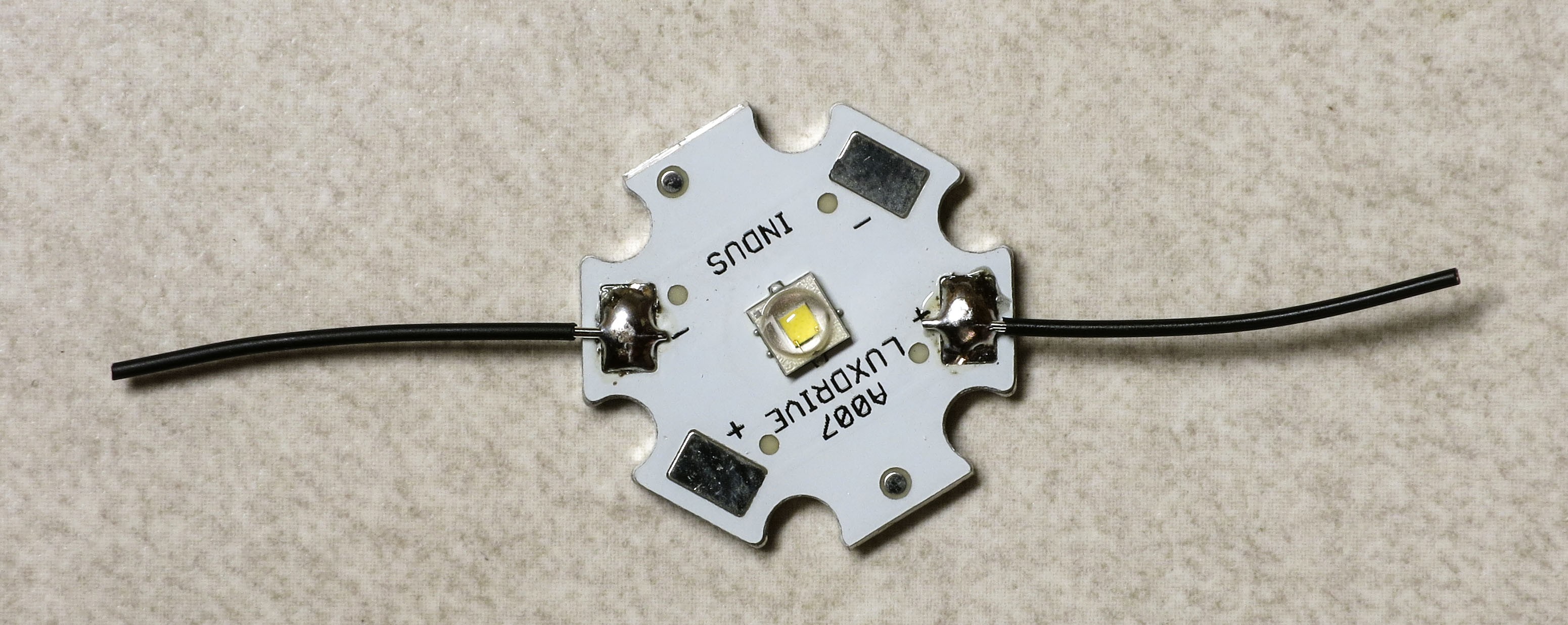
Grab your Kynar 24 AWG wire spool, and strip about 3/16" of insulation (about 3-4mm) off the end. You can make it a bit longer, but try not to make it shorter. Then cut off about 1" of the wire from the spool (about 2.5cm), including the bare lead.
![]()
Repeat this so that you have two of these wires for every LED. Hold the bare wire lead against the solder blob, and press the soldering iron down on the wire to solder the bare wire lead to the solder blob on the LED star pad. Both wires should stick straight out from the LED pads, in line with each other:
![]()
If you mess up, just remove the solder and wires with solder wick or a solder sucker, and try again.
Now strip about 3/16" (3-4mm) off each of the two LED wires:
![]()
Exact length of these wires isn't critical, so if you strip off too much, don't worry about it, just clip it off.
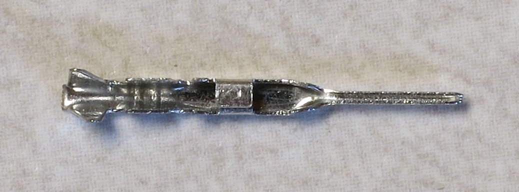
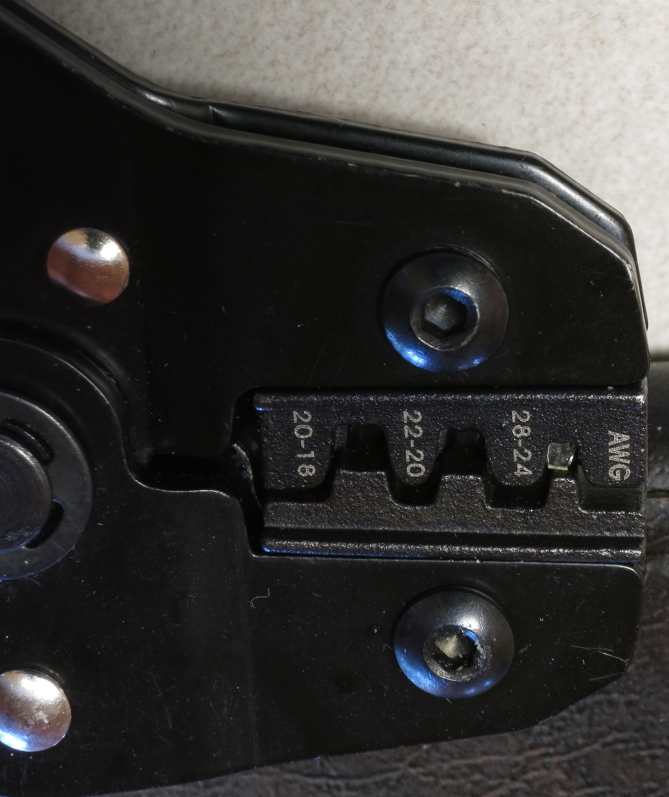
Now you're going to crimp male Dupont pins onto each of the bare wire leads. Hopefully you coughed up the money for a ratcheting crimper, because otherwise this is going to be a bit painful. You might try practicing the following approach with some scrap wires before trying it on a real LED; it may take a bit of practice to figure it out. Here's a Dupont pin pic:
![]()
The pin part is on the right, and there are metal "wings" on the left that the crimper will push down onto an inserted wire and insulation to hold it in place. See that squarish bit in the middle? You want to make sure that you don't stick that into the crimper, but everything to the left of it can go in. Here's the approach I use:
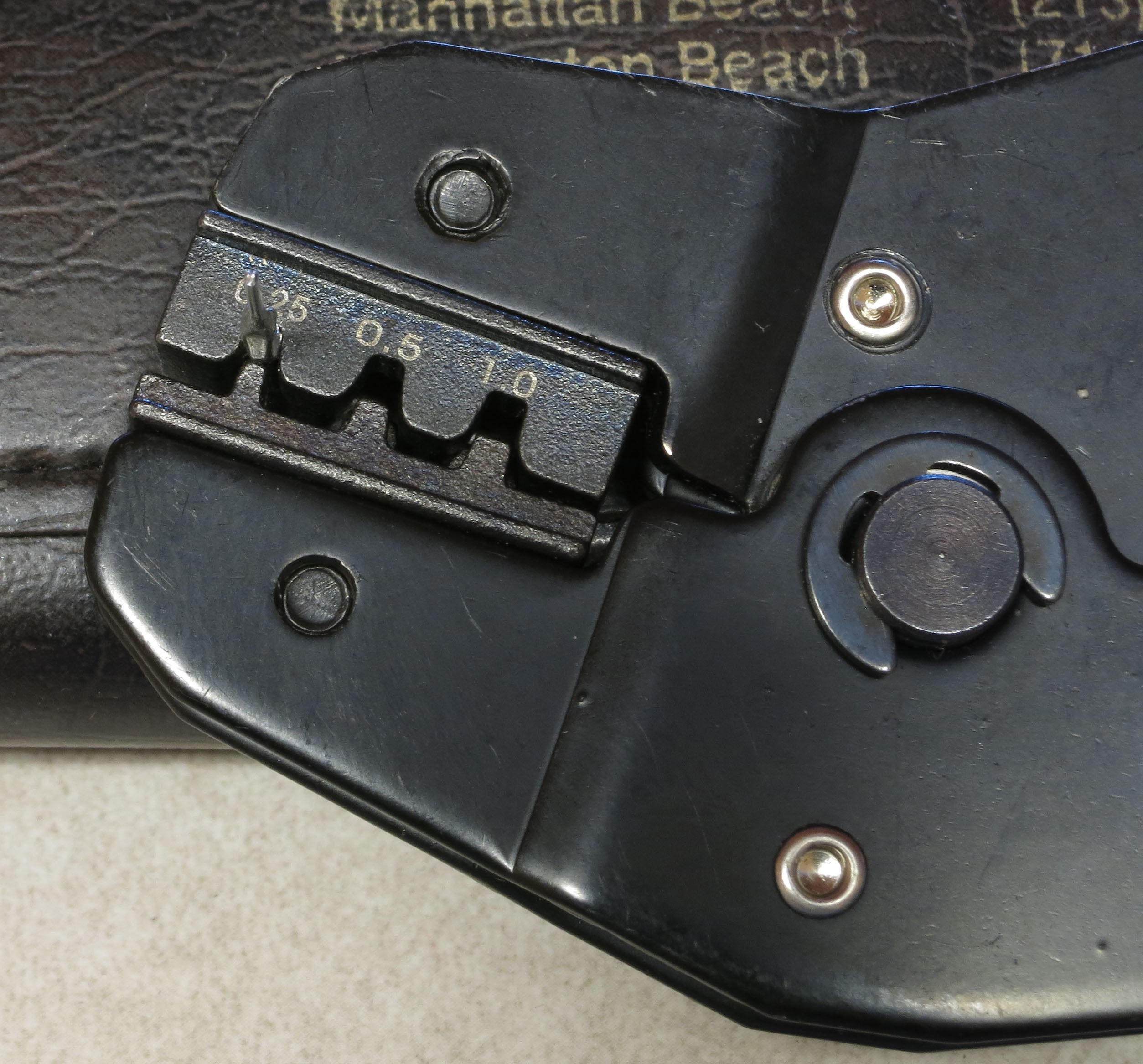
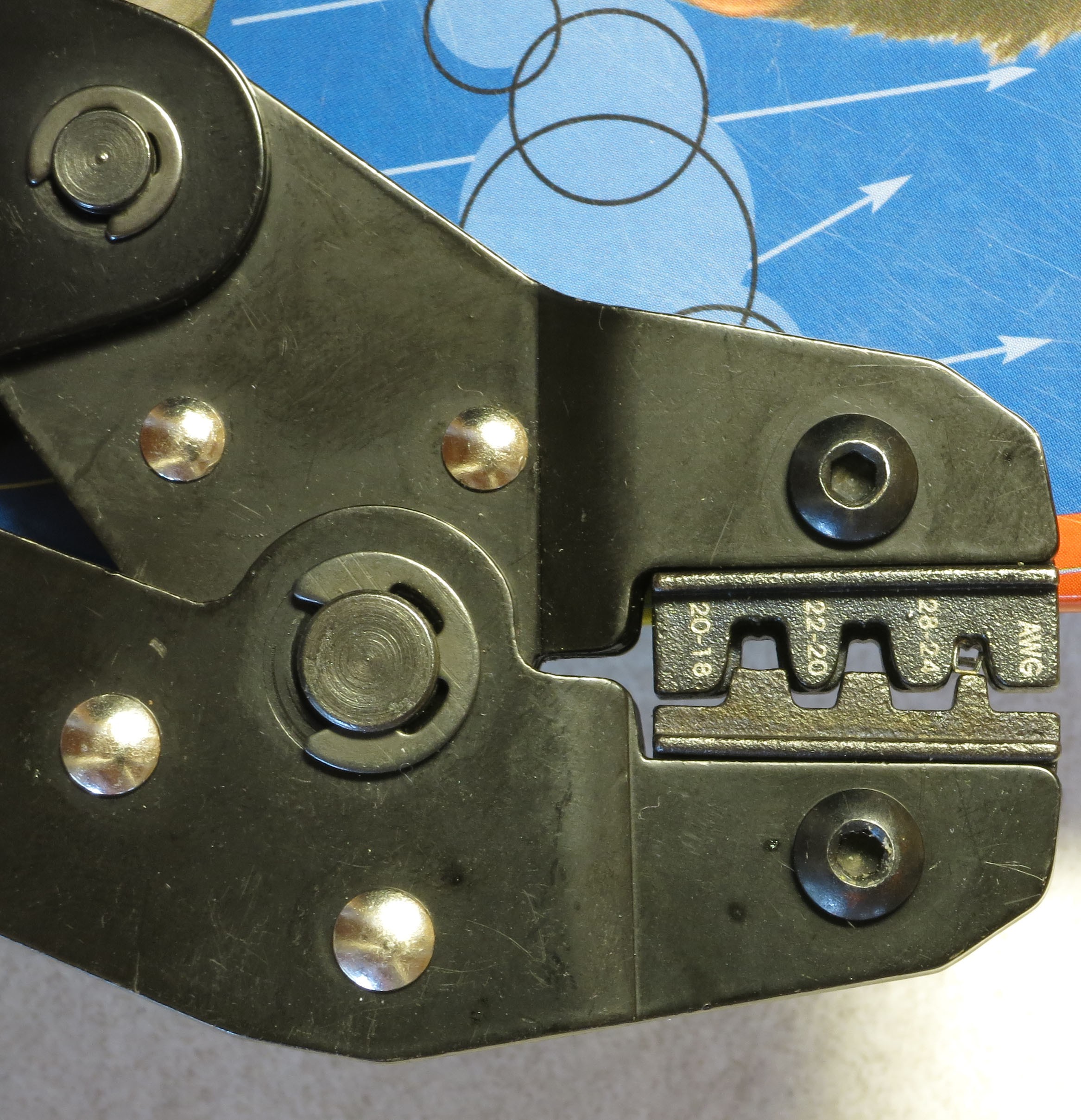
1. Insert the clamp part of the male Dupont pin into the notch marked AWG 28-24, the one furthest to the end. It should go in so that the "wings" you see above face down towards the bottom of the notch. Make sure you don't insert it too far.
2. Start ratcheting down the crimper, click by click, until you see the "wings" start to bend into a rounded square shape at the end. On my crimper, that takes 4 clicks. The pin will now be held firmly in place by the crimper, with the pin sticking out on one side:
![]()
And the "wings" bent into a rounded square shape on the other side (look closely in the following pics and you'll see that):
![]()
![]()
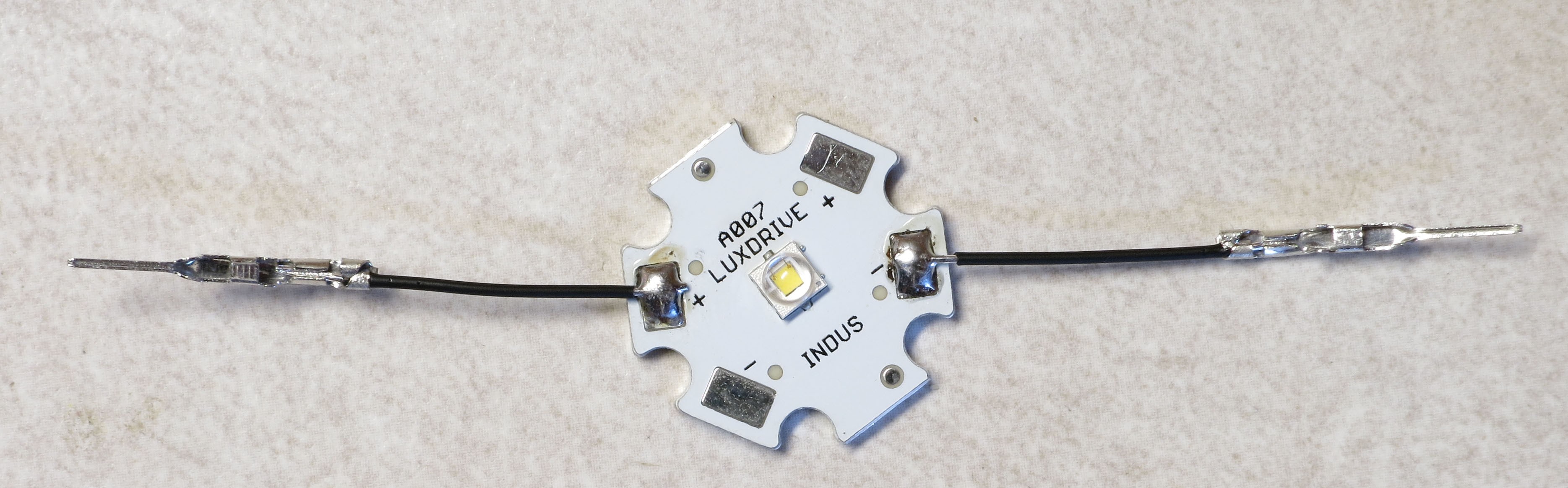
Now insert the bare lead on one of the LED wires into that rounded square so that just a bit of the insulated part goes inside the rounded square. Not super-critical here, but there will be crimping steps coming up where you don't want it to go in too far. It's best to hold the star LED face down for this step, with the LED facing down and the bare metal of the star facing up - this will make an upcoming soldering step a bit easier.
Once the wire has been inserted into the proper position, squeeze the crimper completely to finish the crimping process. The crimper ratchet should release, and you can pull the wire with crimped pin out easily. Repeat on the opposite lead, and you should wind up with a wired star LED that looks like this:
![]()
Notice how the open part of the pin faces up, and you can see the crimped wire inside the pin. In principle, the crimping should be adequate to both hold the wire in place and ensure a good electrical connection. However, probably because I don't do it well, I've had problems with that. So I usually add a bit of solder to hold the wire in place. Use a narrow tip on your soldering iron, and touch the heated tip on top of the place where the wire is crimped in place. Then lightly touch the solder to the area with the crimped wire until just a bit of it flows into place to solder the wire. Too much solder won't hurt with these male pins, but when you solder female pins in an upcoming instruction step, too much solder can clog up the hole and cause problems with later insertion of a male pin. So this is a good time to practice the technique to minimize the amount of solder.
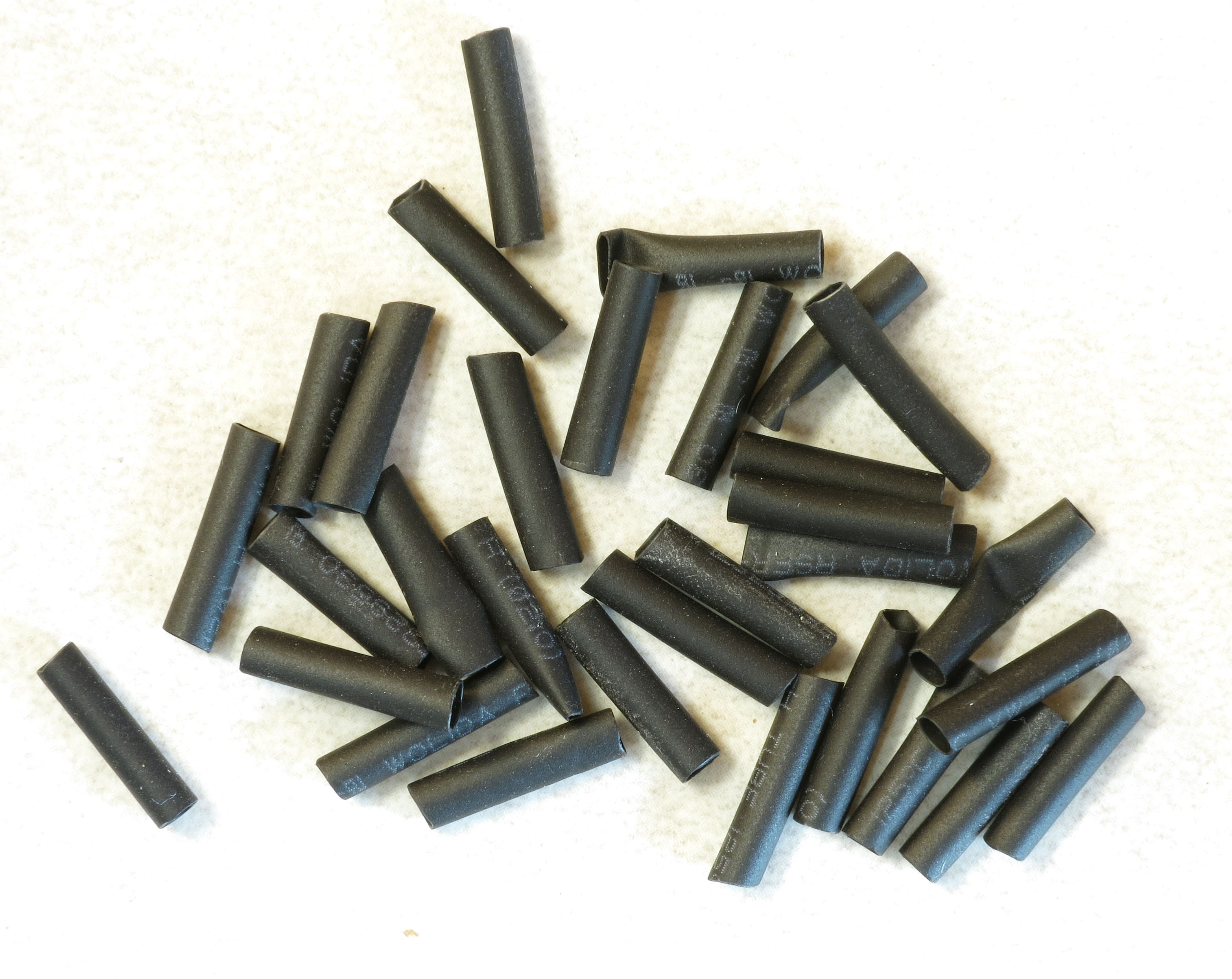
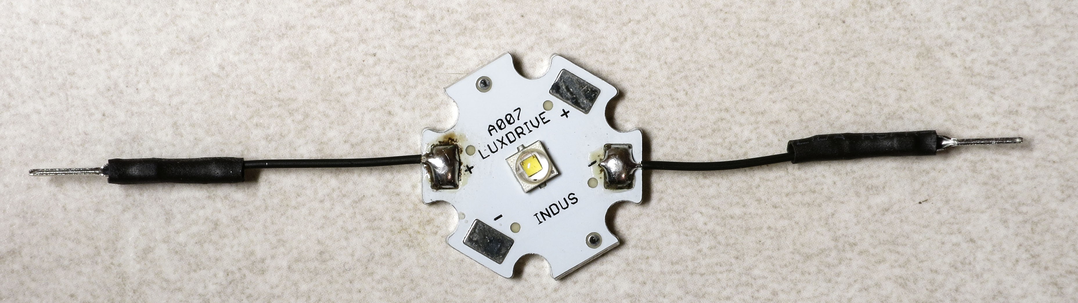
The final step is to add some insulation to cover up all of the metal Dupont pins except for the end pins that will plug in to female pins. Cut two 1/2" (12 mm) pieces of 2mm heat shrink tubing for each LED:
![]()
Place them over the crimped pins, and heat them to shrink them:
![]()
How to heat them? There are two common approaches:
1. Wave a flame, typically from a cigarette lighter, briefly underneath the heat shrink tubing. Not crazy about this approach because of the burn danger, and also because if you hold it too long you can melt the tubing instead of just shrinking it. But it is cheap and readily available.
2. Use a source of hot air. I have used a standard hair dryer to do this successfully, but it requires the "High" setting, and you have to hold the heat shrink right next to the heating element. A heat gun, if you have it, works much better, since it reaches higher temperatures than the hair dryer. You can find one online for less than $20, and sometimes less than $10. Also useful for stripping paint, loosening bolts, and even starting charcoal fires.
You'll need to repeat the process for every LED you have, so that they all look like the picture above. Yes, all of them.
-
18Step 18
18. Preparing the LED connect cables for testing
Now that all the LEDs are wired up, there are two simultaneous tests that need to be done:
1.Test the LEDs to make sure they’re all wired up and working properly
2.Test the MOSFET/CAT4101 driver board combination to make sure it’s working
In order to do this, there needs to be a way to connect the LEDs to the driver board combo.
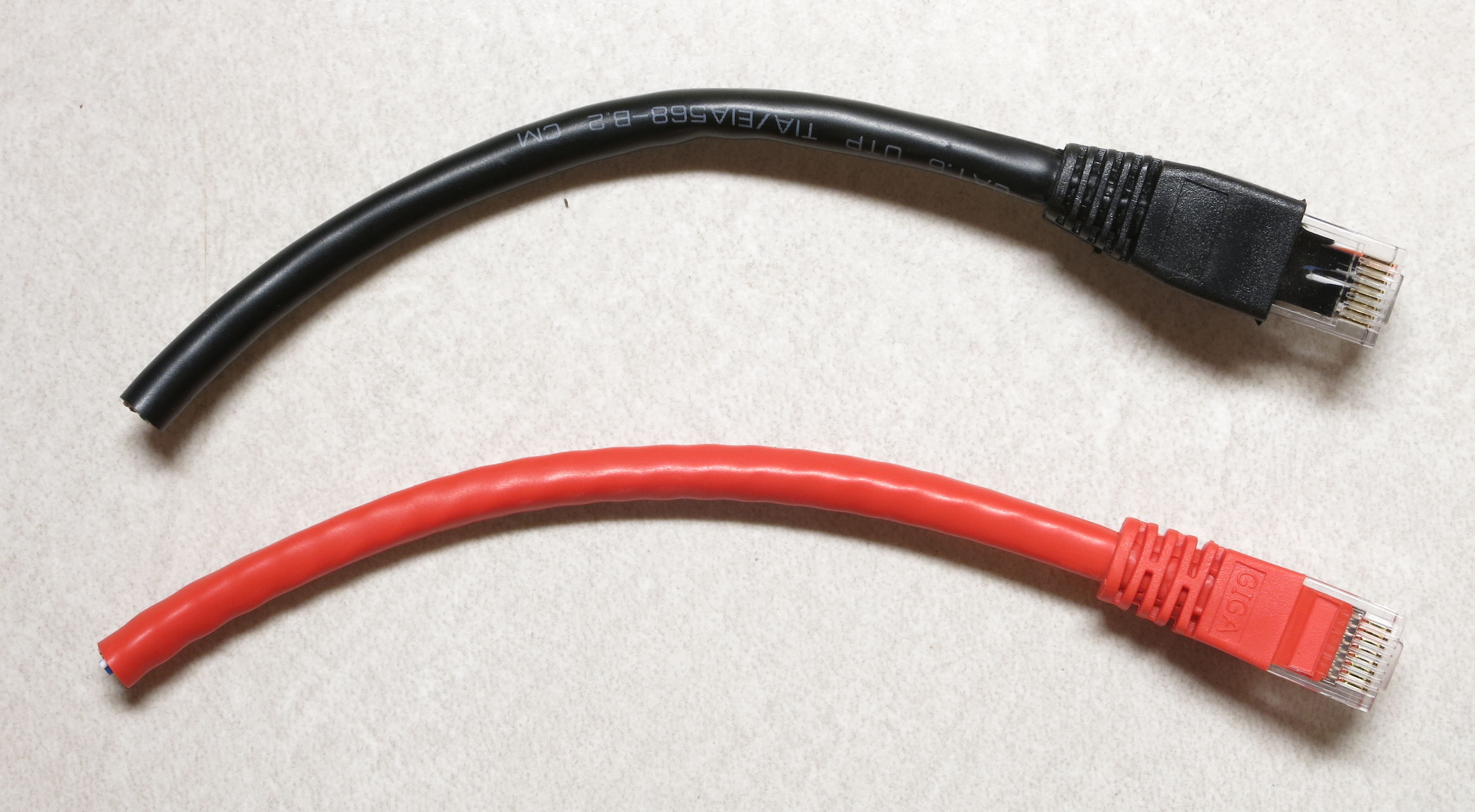
Take the two Ethernet cables you have (red and whatever other color you’ve chosen), and cut about 6” (16 cm) off one end, including the jack.
![]()
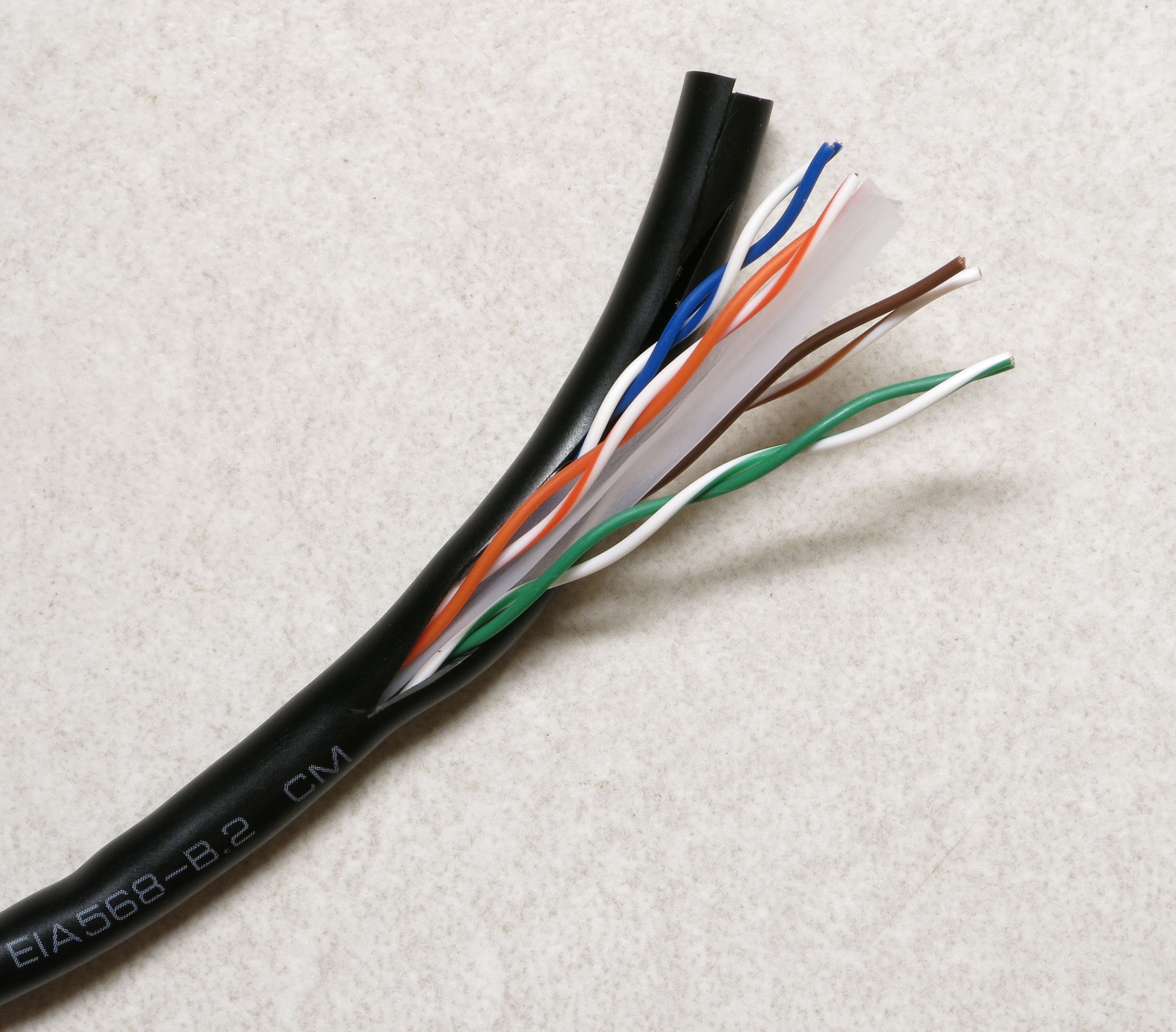
Use a sharp utility or razor knife to slit open the external insulation at the cut end of each cable (cut about 2-3” down the length of the cable), taking care not to cut the wires inside.
![]()
Trim off the external insulation; if the cable has internal plastic ribbing, like the one above, trim that off as well. Separate the 8 wire strands, and strip about 3 mm of insulation off the end of each one.
![]()
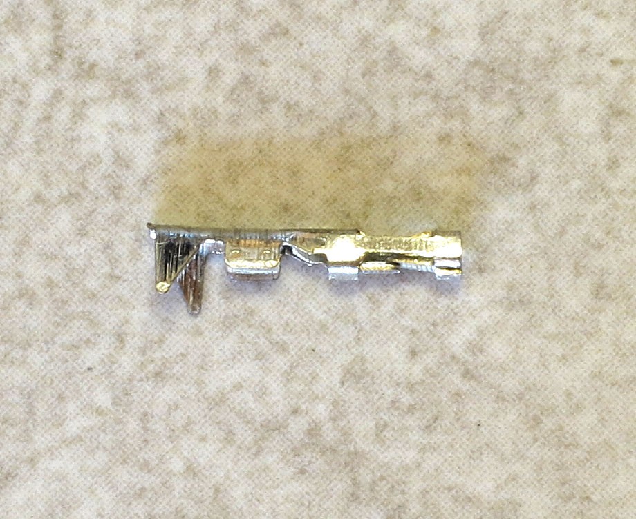
Now crimp female Dupont pins onto the end of each wire, using the same technique as when you crimped male pins onto the LED wire. Here’s a female pin, with the crimpable end on the left:
![]()
When crimping be careful not to insert the wire too far into the Dupont pin, as that may make it difficult later to insert a male pin into the female pin socket. I usually solder the wire to the pin as well for a more secure hold, but be careful with this. Unlike the Kynar wire you soldered to male pins in the previous step, this insulation melts very easily. You just want to touch the soldering iron to the wire crimped in the pin, and immediately touch the solder to the tip of the iron until it just flows a bit; then lift the iron up right away. If you get it wrong, just cut off the pin, strip the wire insulation, and try again. This is good practice for an upcoming step.
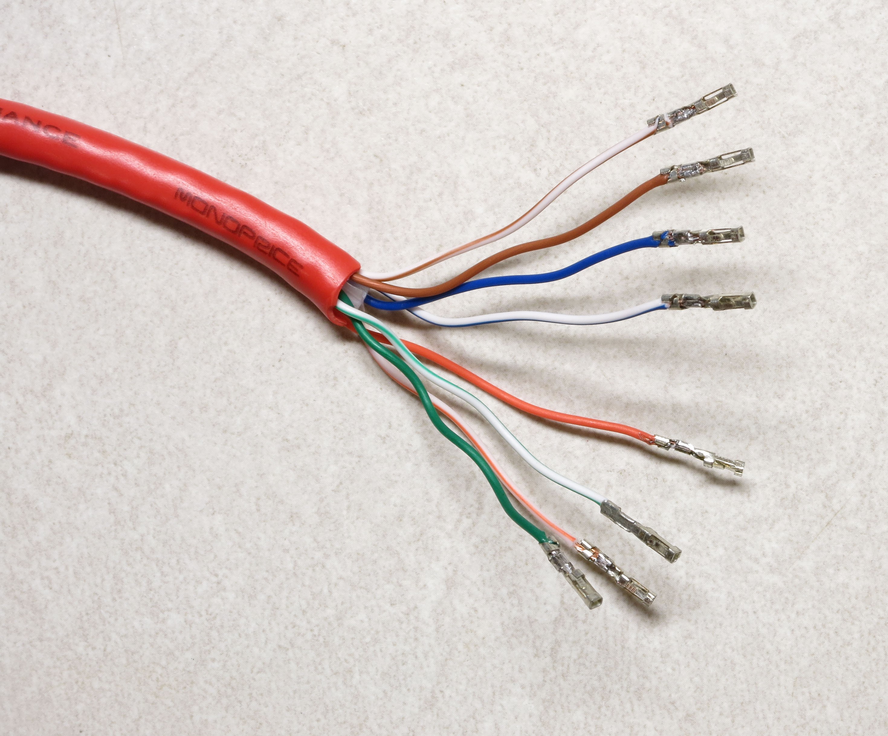
Repeat for the other Ethernet cable:
![]()
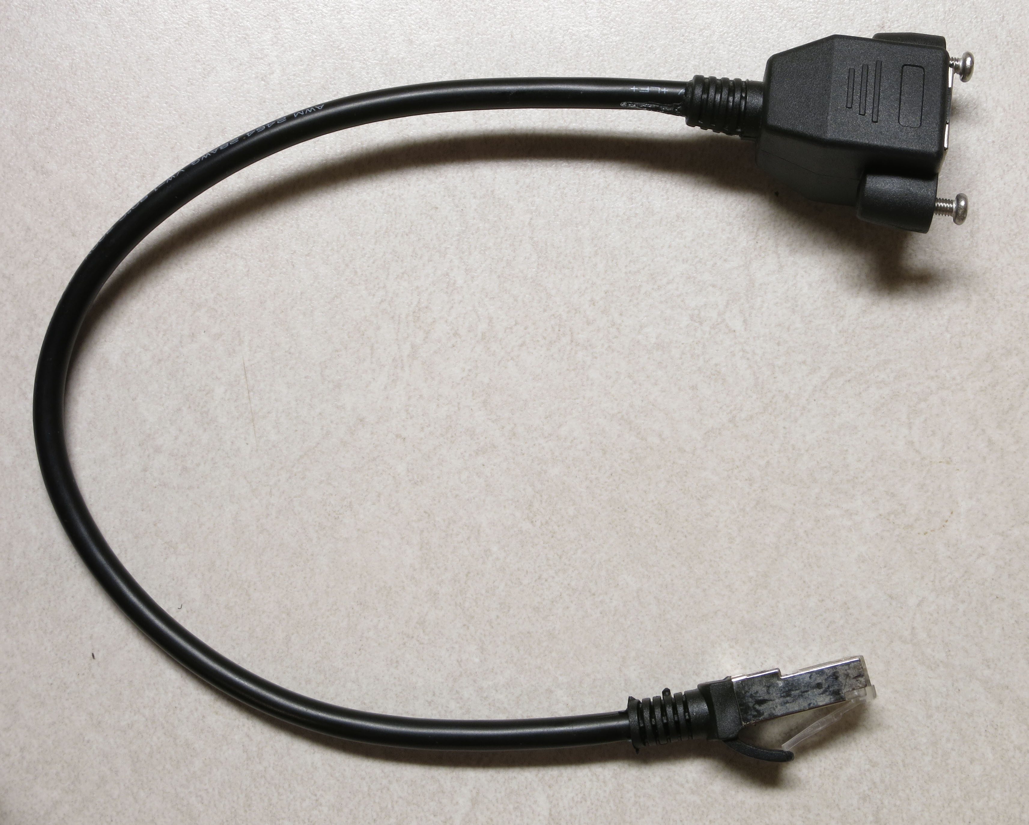
The ground cable connector (black in this case) will plug into the Ethernet jack on the CAT4101 board. The red positive voltage cable needs to plug into the MOSFET driver board, but it can’t do so directly because there’s no Ethernet jack on that board (no room for it). So we have to modify one of the two Ethernet panel jack cables to plug into the 8-pin male header on the MOSFET driver board. Here’s what that cable looks like:
![]()
You want to cut the jack end off as close to the end as possible; that’s the bottom connector in the previous picture. Take care not to cut off the female panel end, the top one above. If you do, you will be very sad, as you’ll have to get a new one. Also, you have two of these Ethernet panel jack cables; only cut the jack end off of one of them.
![]()
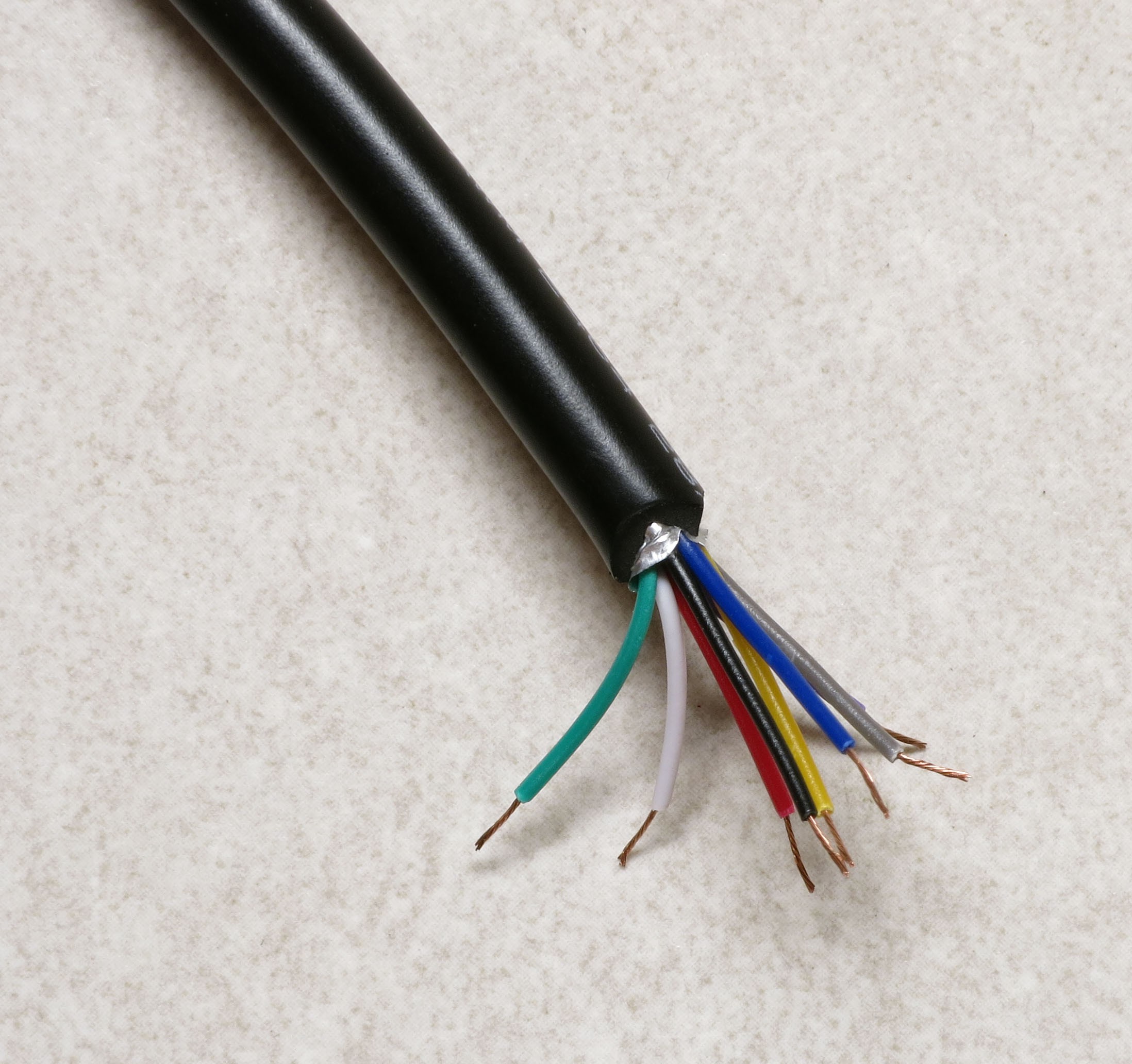
Once again, use a sharp utility knife or razor to cut the insulation about 2” down the length of the cable on the cut end, then trim off the cut insulation, and strip about 3mm off the end of each wire.
![]()
Now crimp female Dupont pins onto the end of each of these wires, and solder them. As before, be careful not to insert the wire too far into the pin crimp end, but make sure that the insulation does go slightly into the pin crimpers. Don’t have a picture of this, but it will look similar to the ends of the Ethernet cables you did before.
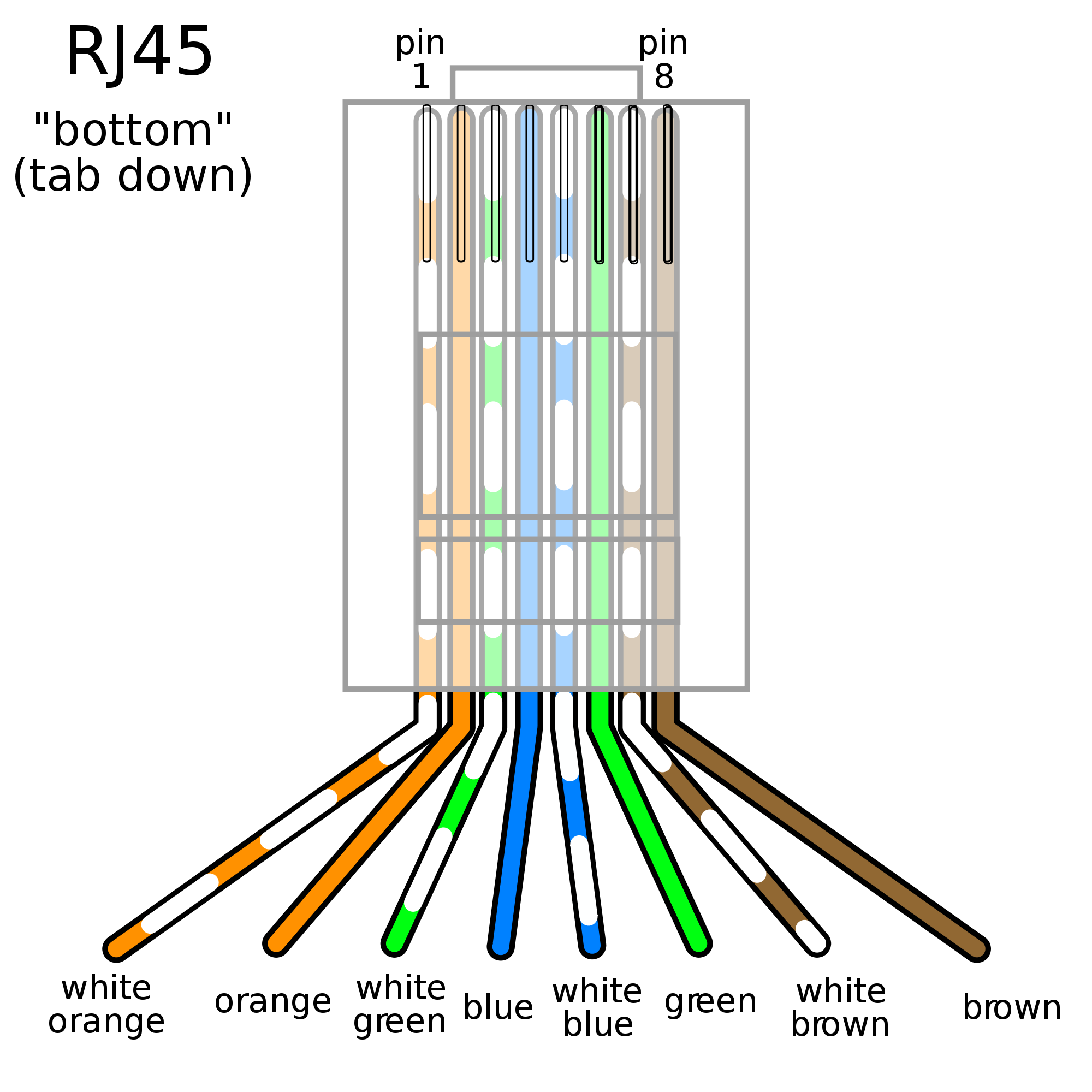
Now there’s a small problem you have to figure out. If you take a look at the first two cables in this step, there’s a good chance they have different wire colors than the Ethernet panel cable you’re currently working with. So you’ll need to figure out which wire color on the Ethernet panel cable corresponds to the matching wire on the Ethernet cable. That’s because each wire connects to a numbered pin on the Ethernet jack, and you want to make sure to have matching pin numbers everywhere. Here’s the numbered wiring color code for the Ethernet cable (standard T568B cable):
![]()
(Source: http://www.polesio.co/utp-cable-wiring/wiring-imgs-199686/)
To figure out which wire on the Ethernet panel cable corresponds to the correct wire on the Ethernet cable, plug the Ethernet cable into the panel jack, then use the continuity checker on your multimeter to figure out which wire is connected to which. In this case, I wound up with the following correspondences:
Pin 1
White/Orange
Green
Pin 2
Orange
Red
Pin 3
White/Green
Yellow
Pin 4
Blue
Gray
Pin 5
White/Blue
Purple
Pin 6
Green
Blue
Pin 7
White/Brown
White
Pin 8
Brown
Black
Your wire matchups may differ; just be sure to write down which color corresponds to which pin.
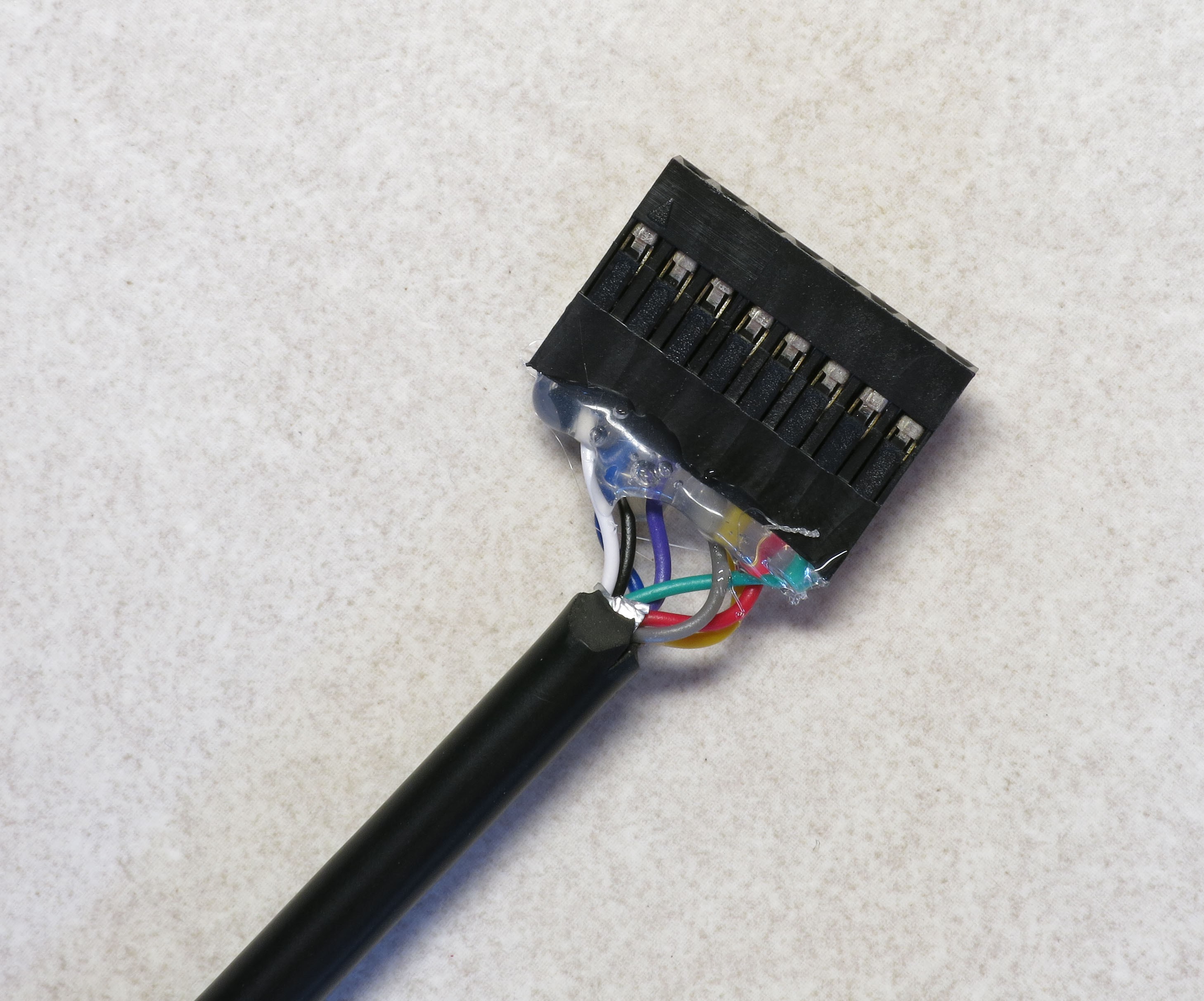
Next, grab the 8-pin 2.54mm single row female pin header, and insert the female Dupont pins into the large end of the header in pin order, i.e. #1 at the top, then #2, #3 all the way down to #8 at the other end. The pins need to be pushed all the way down into the header, not just until the end of the pin is flush with the top of the header. You may need to use a small screwdriver, or a thick wire, to push it all the way in. The top of the female Dupont pin (with the crimped wire visible) should be inserted into the header so that it will be visible in the header’s open hole, like this:
![]()
A couple of points here:
1.I cut the wires a bit shorter than 2”, and it was a pain to get them to fit; that’s why I recommend at least 2” in length.
2.I have the wires in correct order here, from 1 on the right to 8 on the left, but I would have done better to put them in in the reverse order. See that little arrow at the top left? That’s supposed to indicate pin 1. It’s not a big deal, as long as I remember to insert this cable into the 8-pin male header on the MOSFET driver board so that the #1 wire (green) is at the top. But doing them in reverse, I wouldn’t have to remember which color wire is the #1 wire.
3.Test the connections using a multimeter, to make sure that none of the wires got damaged when you inserted them into the female pin header.
4.I used some hot glue to glue the wires in place so that they wouldn’t pull out by accident, and I’d recommend that once you’ve tested the connector to make sure it’s working properly, you use some kind of glue to do the same. When inserting or removing this connector, never pull it out by the wires – always pull on the connector.
5.If you can’t find an 8-pin 2.54mmm single row female pin header, you can use 8 1-pin female Dupont connectors, one for each wire. It’ll be a bit of a pain as you’ll have to connect each of the 8 wires individually to the MOSFET driver board, but it can be done.
-
19Step 19
Now that you’ve got all the test cables done, it’s time for the big test of the electronics and LEDs.
1.Connect the Arduino Mega to your PC with the USB cable, and upload the testing program RTIMage_System_tester.ino into the Arduino Mega controller using the Arduino IDE; you’ll find that program in the Files section. Disconnect from the cable when done. Note: There's a step further down that talks about how to set up the Arduino IDE to upload software; can't seem to move it ahead of this step.
2. Plug the MOSFET driver board shield into the Arduino. Do this slowly and carefully – it’s easy to misalign pins, or bend them when inserting the shield.
![]()
3. Plug the CAT4101 board into the MOSFET driver board.
![]()
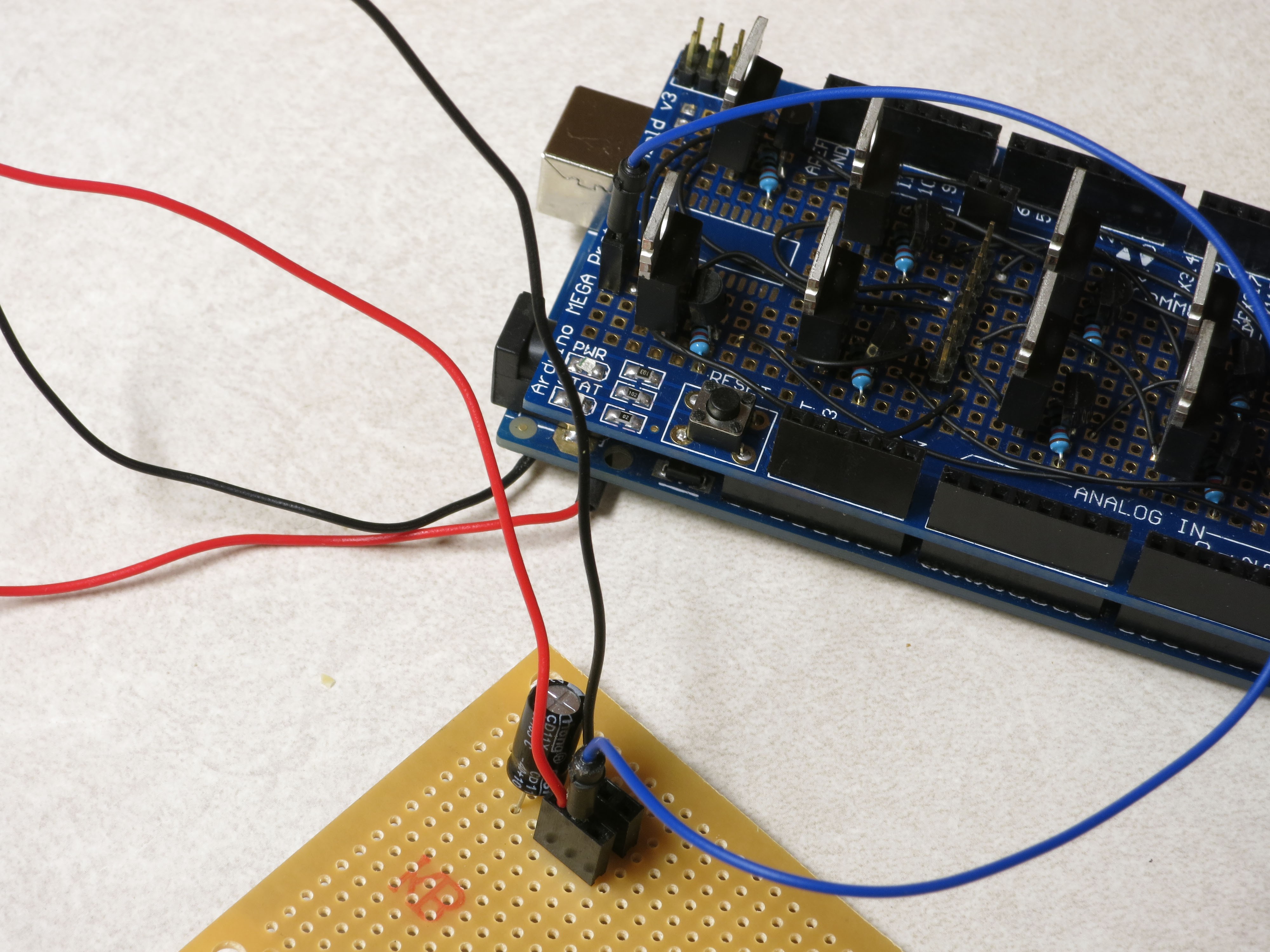
4. Plug the black ground wire soldered to the Arduino power input into the top left header of the power strip board (next to the capacitor half marked with a white stripe), and plug the red positive wire into the bottom left header. These are for the main power supply to the LEDs.
![]()
5. Connect a jumper wire between the positive power strip header and the two pin header on the lower left side of the MOSFET shield board (the blue wire in this picture); this connects positive voltage to the MOSFETs:
![]()
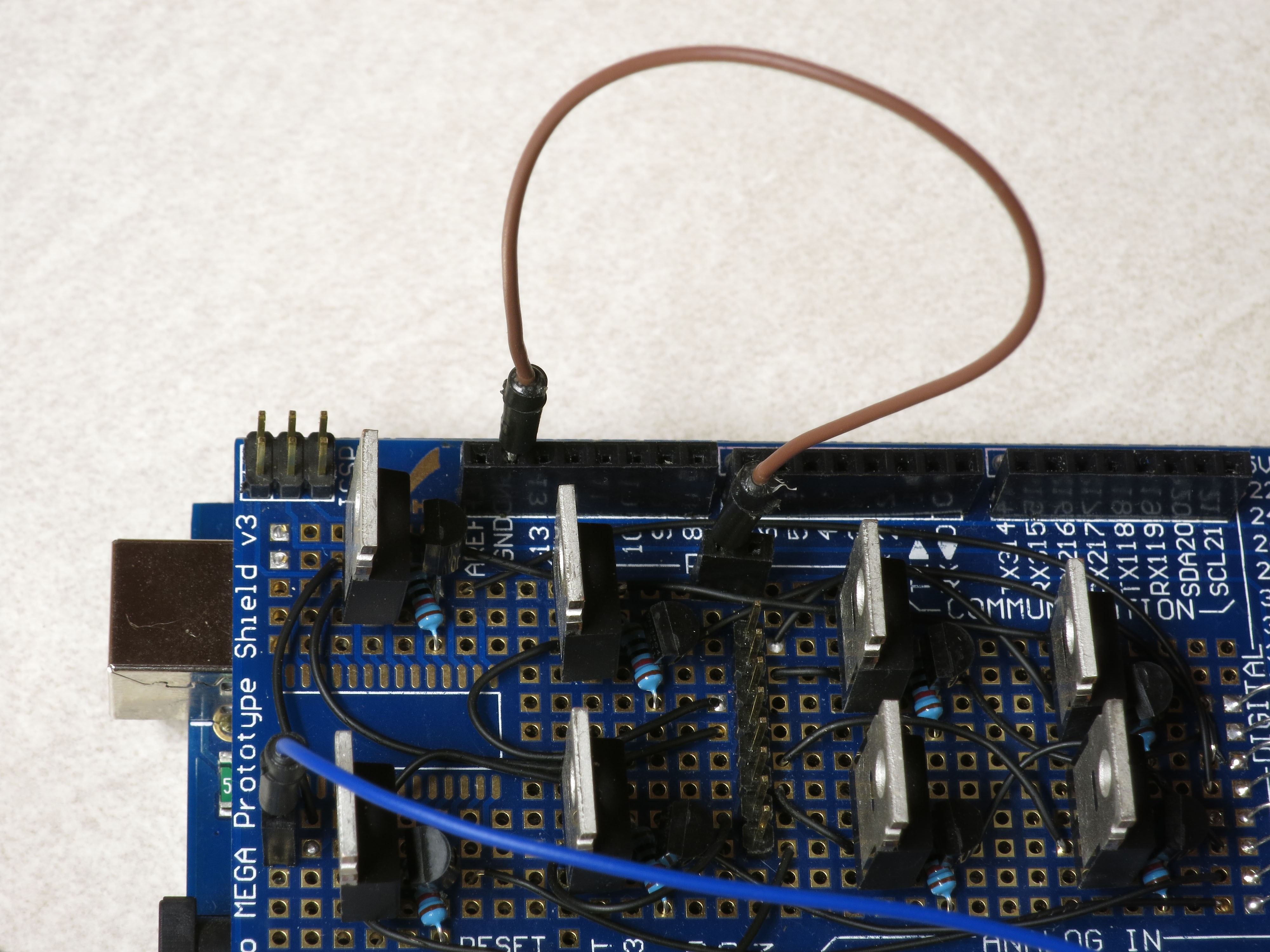
6. Connect a ground header on the MOSFET driver shield to the two-pin female header in the top center of the board using a jumper wire, the brown wire in this picture; this grounds the emitter pin on the npn transistors.
![]()
7. Connect a jumper wire to the ground power strip header on the power board, and the two-pin header on the far right of the CAT4101 board (the green wire in this picture); this ultimately connects the LED ground to the power supply ground:
![]()
8. Plug the unmodified Ethernet panel cable into the Ethernet jack on the CAT4101 board, then plug the ground Ethernet tester cable you made in the previous step into the panel jack; this will connect directly to the LED ground.
![]()
9. Plug the modified Ethernet panel cable you made in the previous step, with the 8-pin female header, into the 8-pin male header on the MOSFET board. Make sure that pin/wire #1 is at the top.
![]()
10. Plug the red Ethernet cable with the female Dupont pins on the end into the modified Ethernet panel cable connected to the MOSFET driver board; this will be the positive voltage supply to the LEDs.
![]()
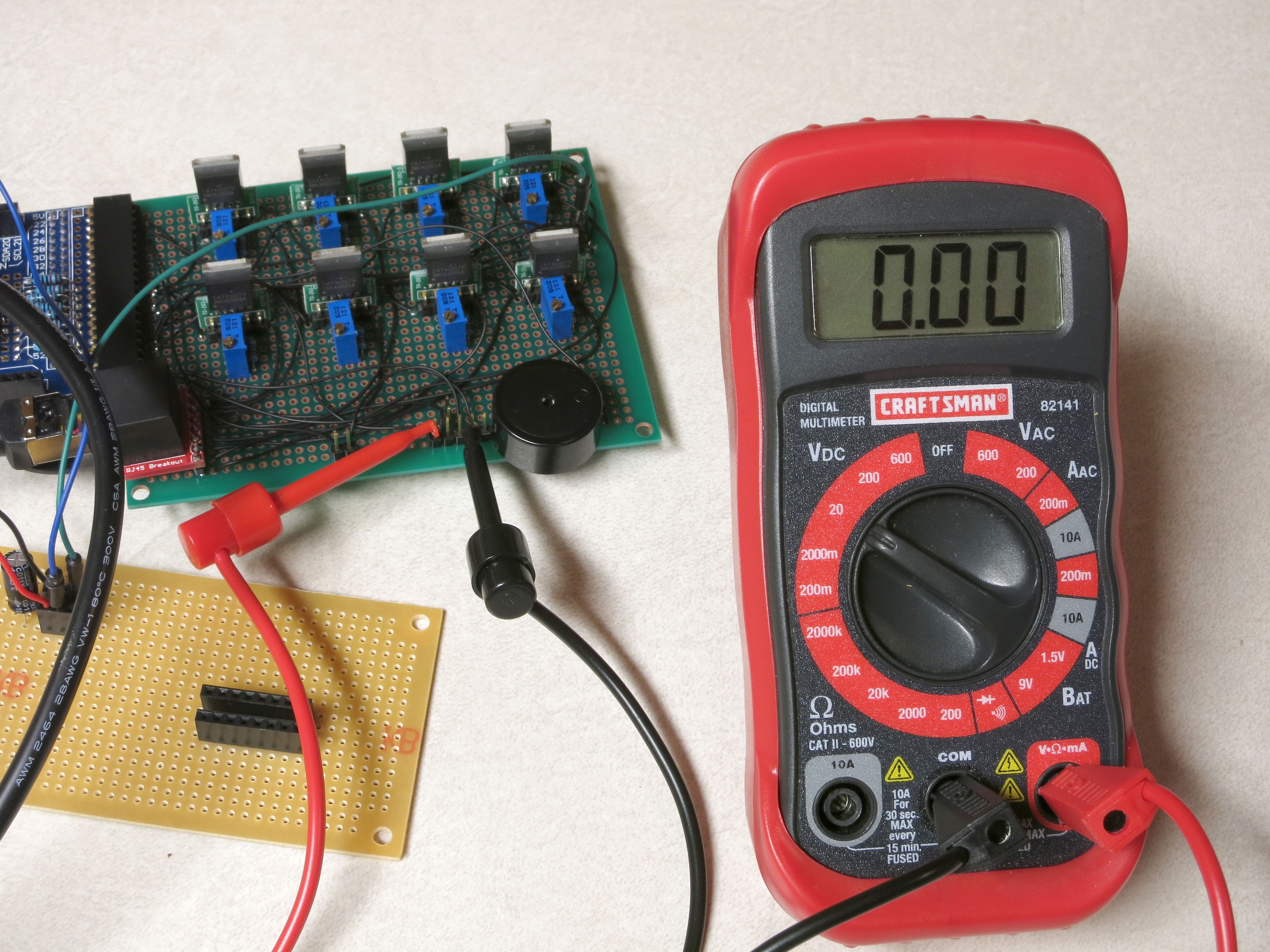
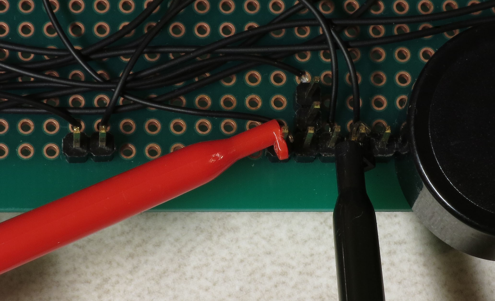
11. Connect multimeter leads to the male header pins at the bottom of the CAT4101 board, and set the multimeter to a voltage scale greater than 5V DC. When the tester is running, it will turn on and off voltages to two of these pins, and supply constant 5V to a third pin. Here’s the connection to the pin that supplies 5v to the USB cable or IR LED to fire the camera shutter; this should cycle to 5V on and off as the LEDs turn off and on:
![]()
And here’s a closeup of that USB shutter multimeter hookup:
![]()
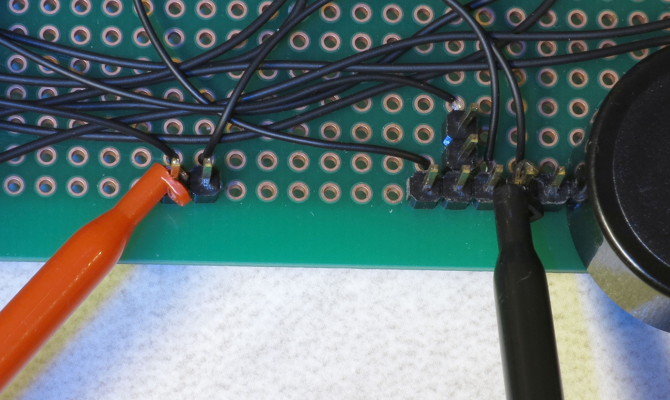
Here’s a closeup of the testing connection for the servo control pin; this one should also cycle on and off as the LEDs turn off and on:
![]()
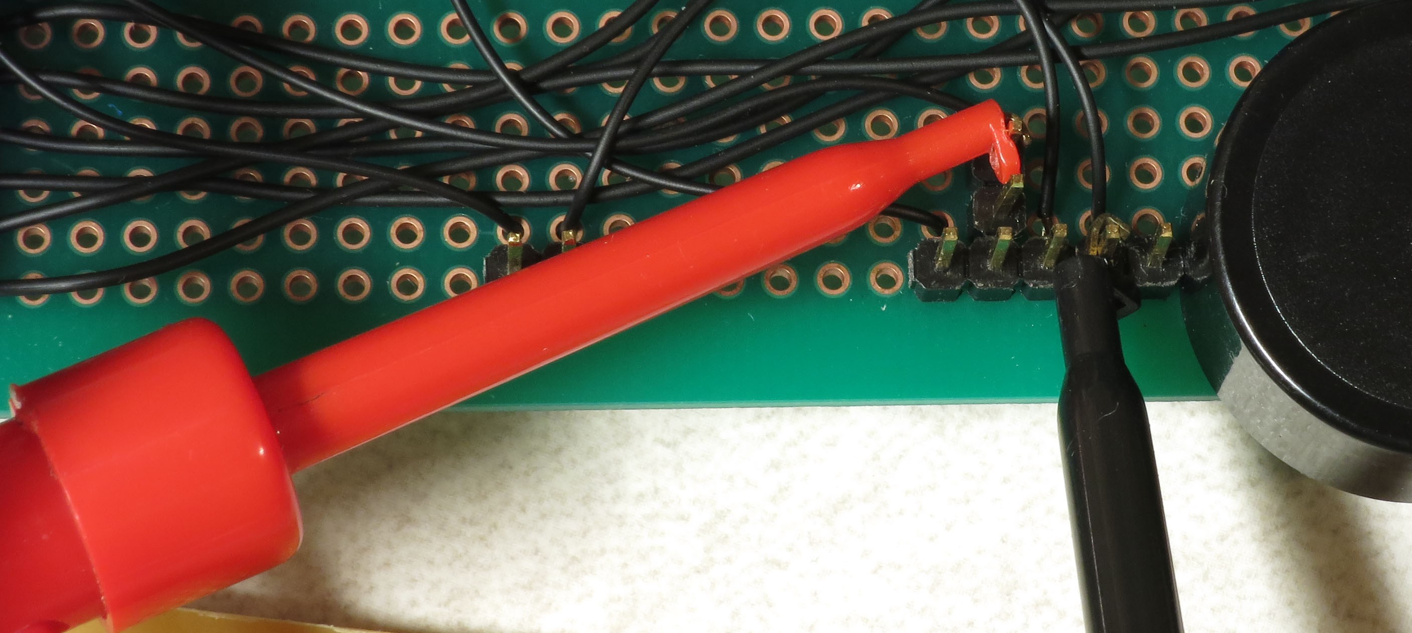
And here’s the connection for the constant 5V that powers the servo; this should stay at a constant 5V:
![]()
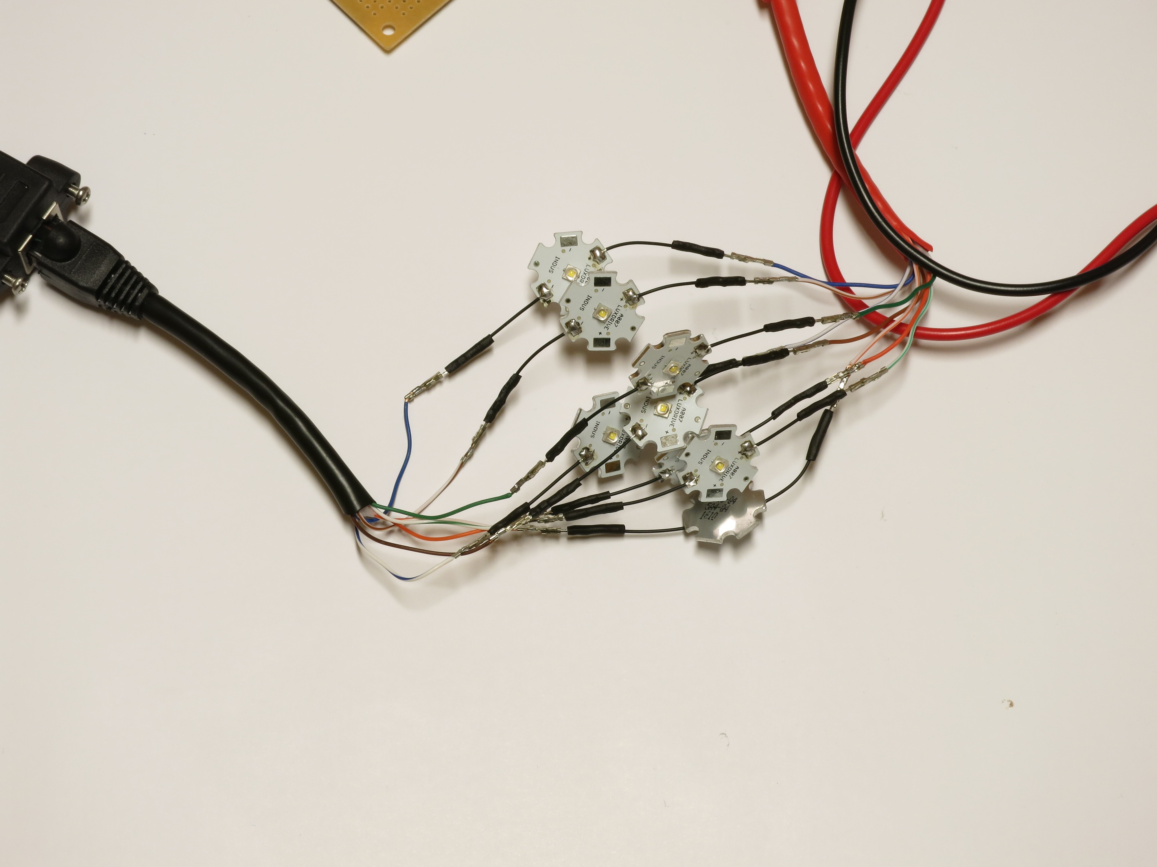
12. Grab 8 of your 3W Cree Star LEDs, and plug the positive LED wire into the positive Ethernet connector wires (should be from the red one, coming from the MOSFET driver board). Then plug the negative LED wire into the matching wire from the ground Ethernet connector (black) from the CAT4101 board. In other words, orange/white to orange/white, green to green, white/brown to white/brown, etc. . You’re connecting the #1 column wire to the #1 row wire, the #2 column wire to the #2 row wire, etc.. The tester program will turn on matching row/column number drivers simultaneously, which should light up each LED in sequence.
![]()
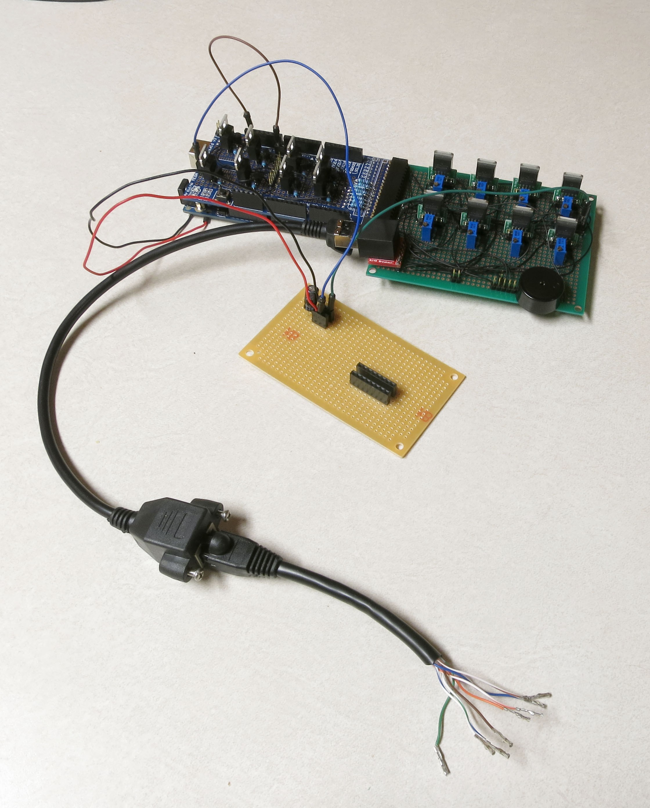
Now you’re ready to plug in the 9V power supply into the Arduino – the full setup should look something like this:
![]()
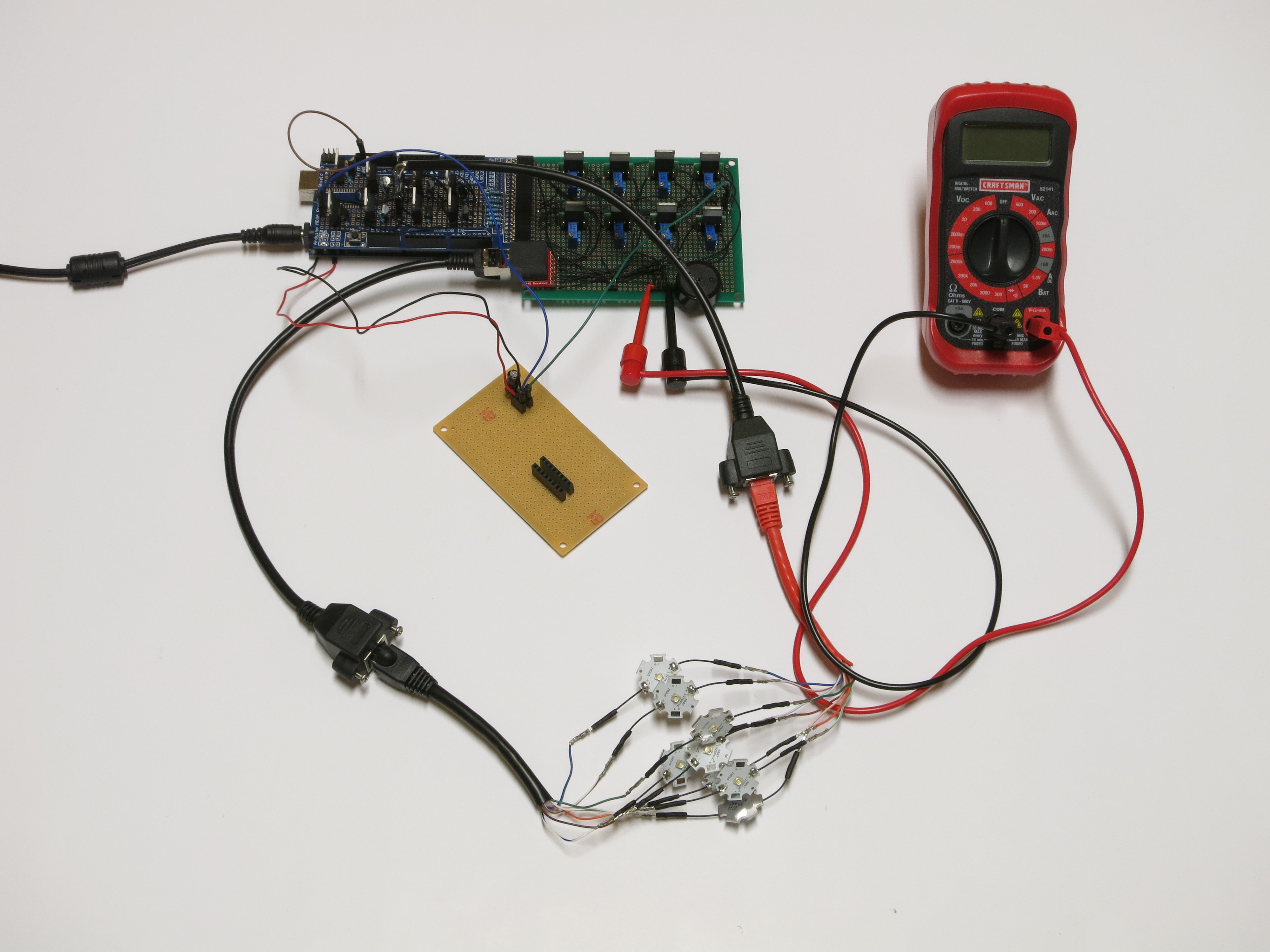
If everything is working correctly, the beeper should sound, and each LED should turn on individually in sequence for 0.5 seconds (500 milliseconds), then turn off. While the LED is on, the multimeter voltage should read zero when connected to either the USB/IR pin or the servo control pin; when the LED is off, it should read zero. When connected to the servo power supply, it should always read 5V.
If everything is working as it should, it will look something like this:
If you see this, congratulations! The rest of the build should be straightforward in comparison to what you've done so far.
If it is working, then once you’ve cycled through all 8 LEDs at least once, unplug the power supply and disconnect all 8 LEDs, setting them aside. Grab a different set of 8 LEDs, and connect them to the wires as you did the first set. Plug in the power supply, and let the LEDs run through at least one full cycle to make sure they’re all working. Once that’s done, repeat the process until you’ve tested every LED to make sure it’s working correctly. If you plan to finish assembling the dome before you put the control box together, leave this setup untouched – you’ll need it to test the dome to make sure it’s wired correctly. If you will put the control box together before the dome, feel free to disassemble all the components. The latter actually makes sense, since the dome will have to sit a day after you install the LEDs to let the adhesive dry, before you can do the wiring.
If it’s not working, here’s some quick things to check:
1. Make sure the + leads on the LEDs are connected to the wires from the red cable, which should in turn connect to the MOSFET driver board.; the - leads should connect to the black cable coming from the CAT4101 board.
2 .Make sure the LEDs are connected to wires of matching colors.
3. Make sure the female 8-pin header is firmly connected to the MOSFET driver board, and that the #1 pin connection is at the top.
4. Double-check to make sure that all the jumper and power wires are correctly positioned, and firmly seated in the female headers.
5. Make sure the power supply is properly plugged in.
If that doesn’t fix the problem, you’ll need to double-check the soldering and wiring on both boards to make sure you did it right.
-
20Step 20
Installing the LEDs inside the dome
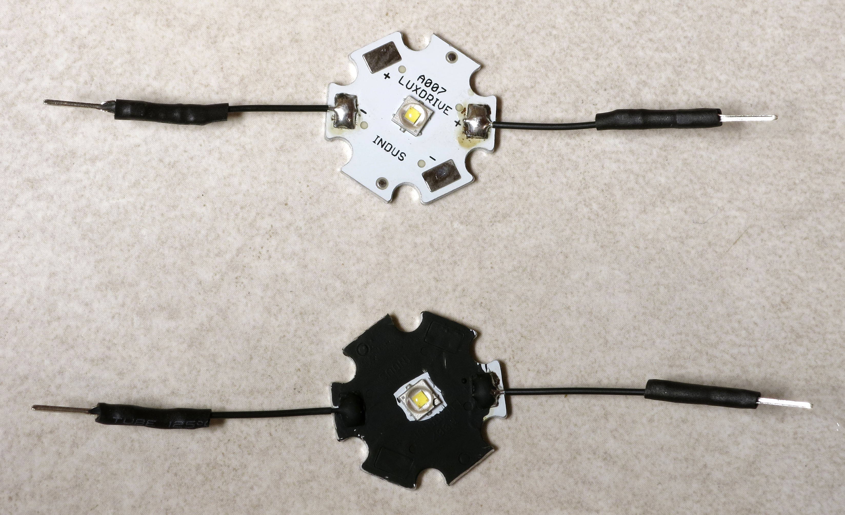
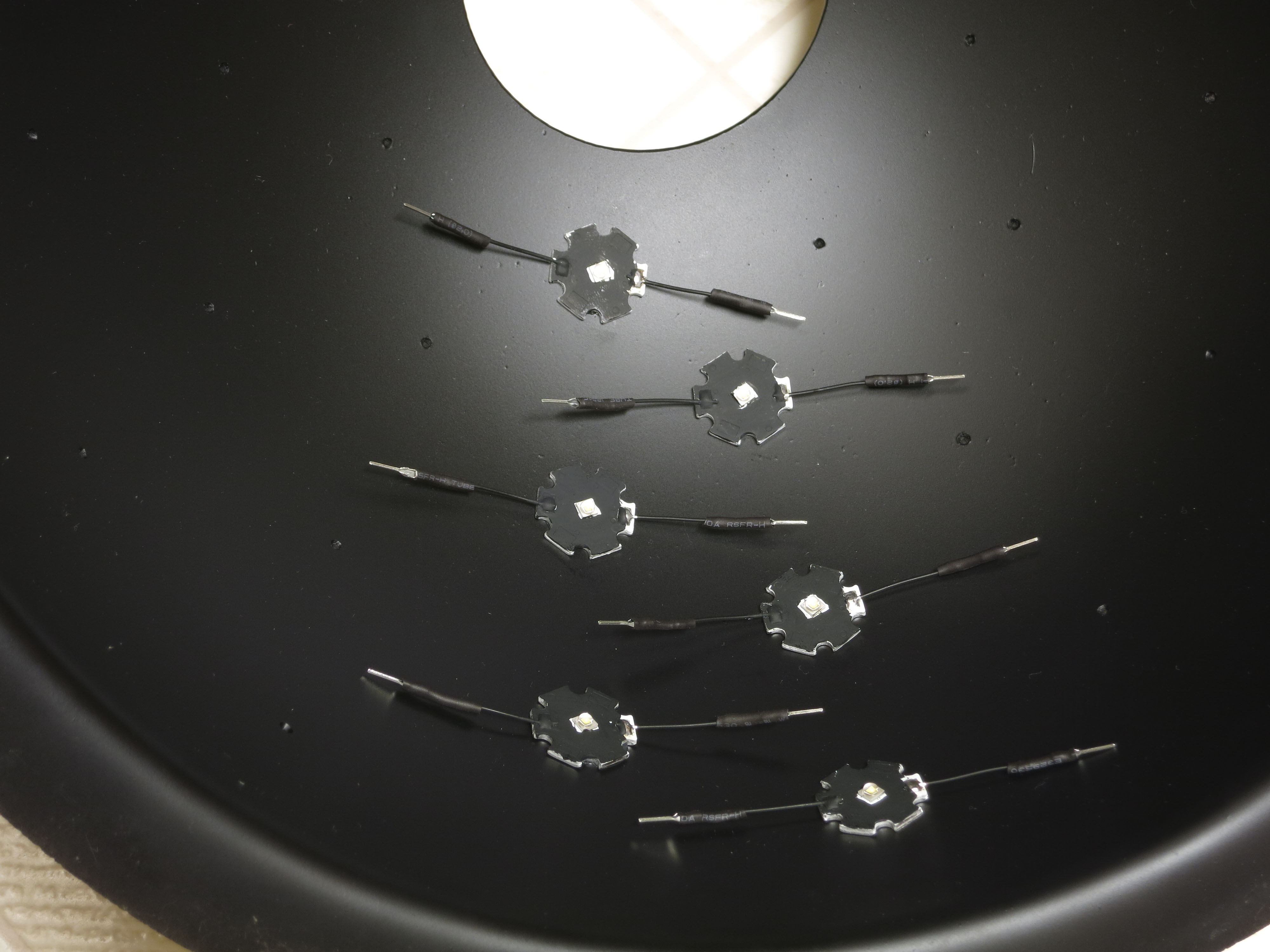
Once you’ve tested all the LEDs, it’s time to mount them inside the dome. But there is one final consideration. The interior of the dome was painted flat black to minimize light scattering. But you’re about to install LEDs that are mostly white in color, and will scatter light quite effectively. I calculated that for the 12” dome I’m building here, the 48 LEDs will cover about 10% of the total area inside the dome, which could lead to quite a bit of scattered light. To reduce that, I paint the LEDs with a non-conductive flat black paint:
![]()
However, since I still need to know which wire is positive and which negative/ground, I leave a little bit of the end next to the positive wire unpainted so that I can keep track of the polarity.
To install the LEDs inside the dome, I put a small dab of adhesive on the back of the LED. I use a silicone-based adhesive because I’ve found that if you don’t use too much of it, it’s possible (with some effort) to pry off the LED if something goes wrong. You then press the LED on top of one of the position markings you created way back in step one, with the positive lead facing to the right as you look directly at it:
![]()
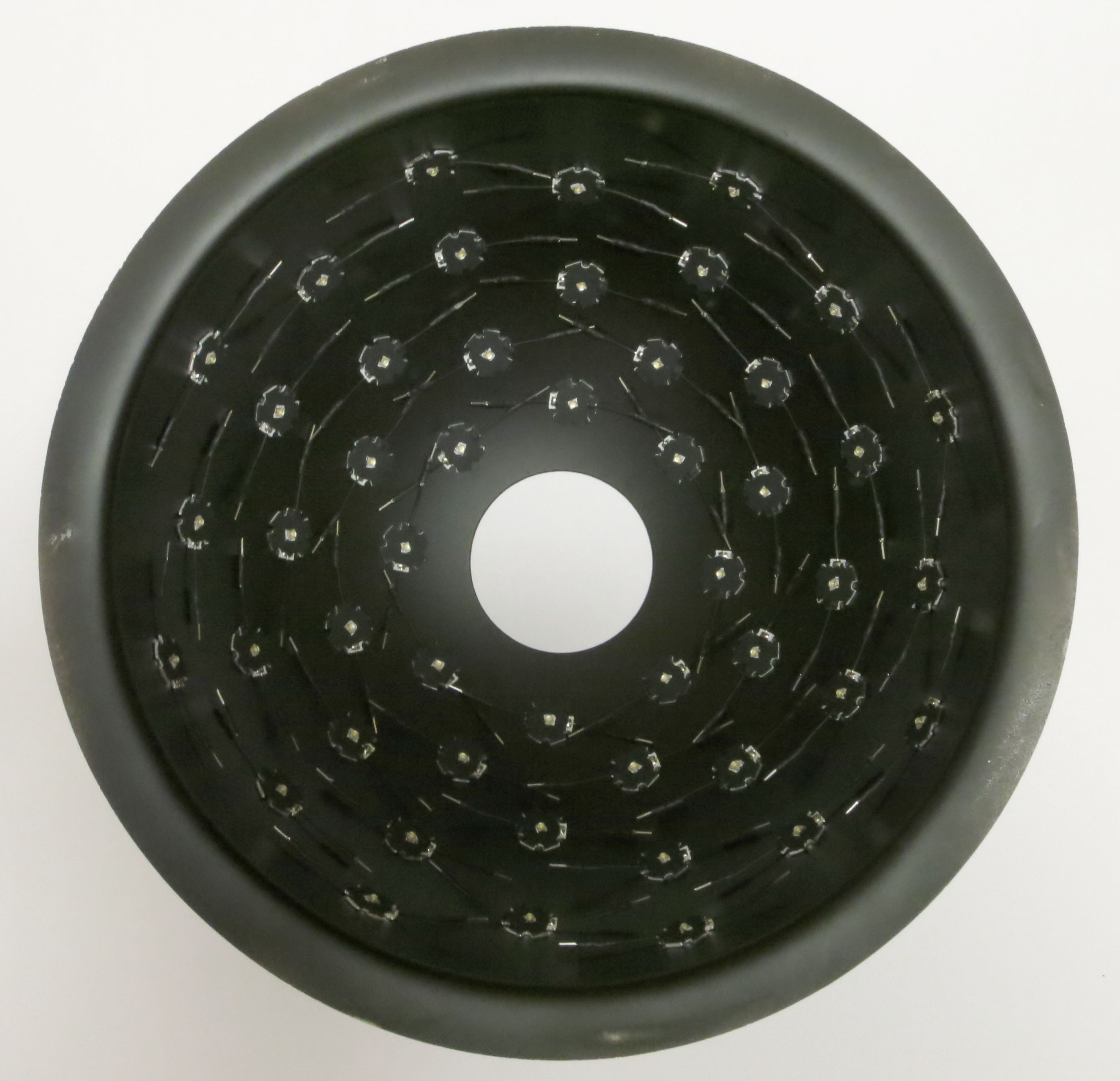
Continue the process until all of the LEDs have been installed:
![]()
Before the adhesive dries, check to make sure that all of the LEDs have the positive lead facing to the right, and the wire leads face left and right when you look directly face on at the LED. Once you’re sure everything is oriented correctly, set the dome aside to allow the adhesive to set for at least 12 hours, and preferably 24.
It may look like an intimidating amount of wiring needs to get done, but don’t worry – there is a method to the wiring madness that keeps it from being too complicated to keep track of.
Affordable Reflectance Transformation Imaging Dome
A simple and inexpensive way to image and analyze subtle surface details on objects.
 There are 5 leads on the CAT4101. From left to right:
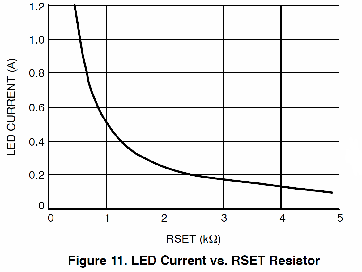 5. LED: Connects to the ground lead of the 3W LED you're lighting up.
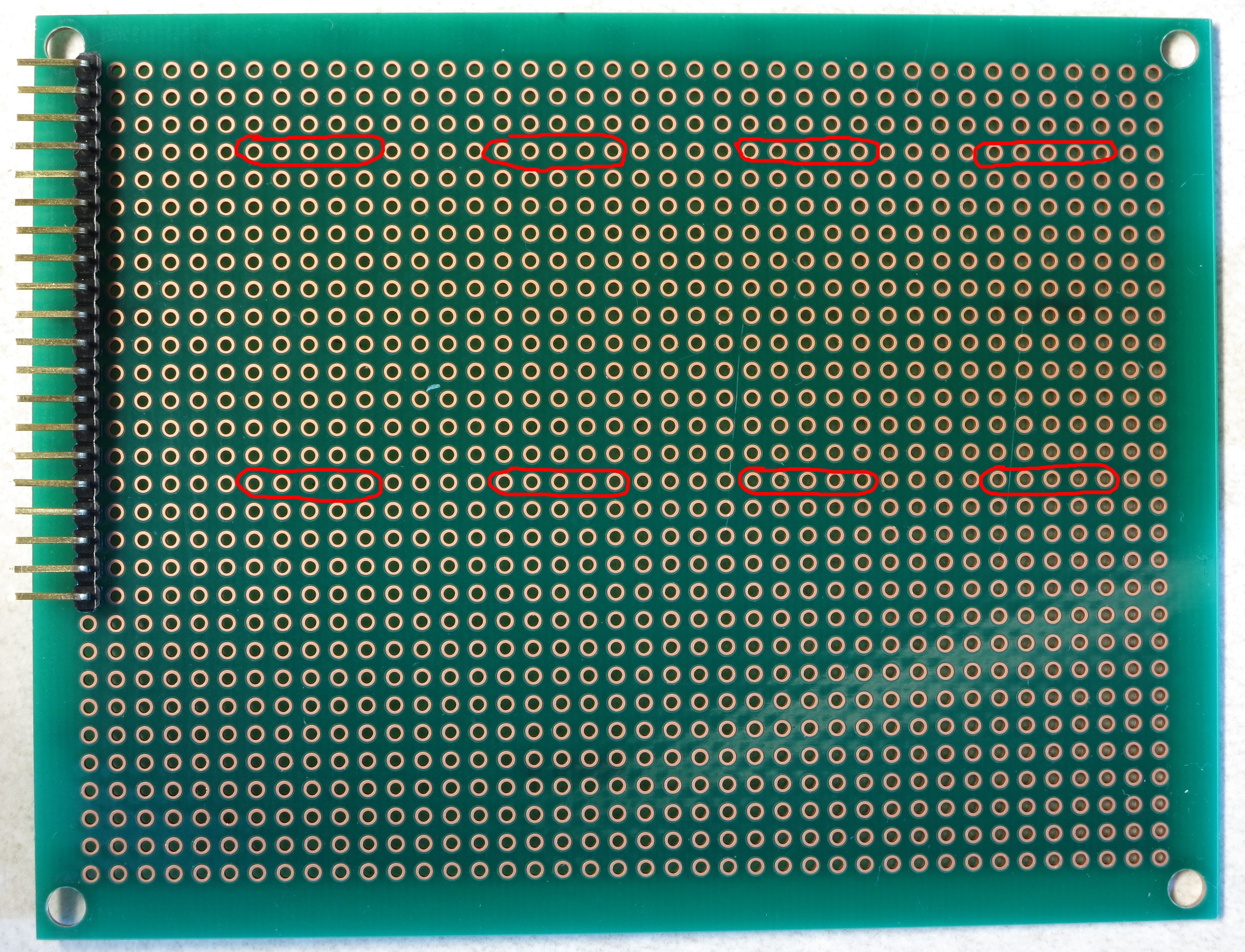

 If you're using the protoboard recommended in the parts list, this is the correct position for it, all the way down in the lower-left-corner. Sliding the whole protoboard into the MOSFET shield board, it will just barely clear the edge of the board (and if it doesn't, a bit of filing should fix that):
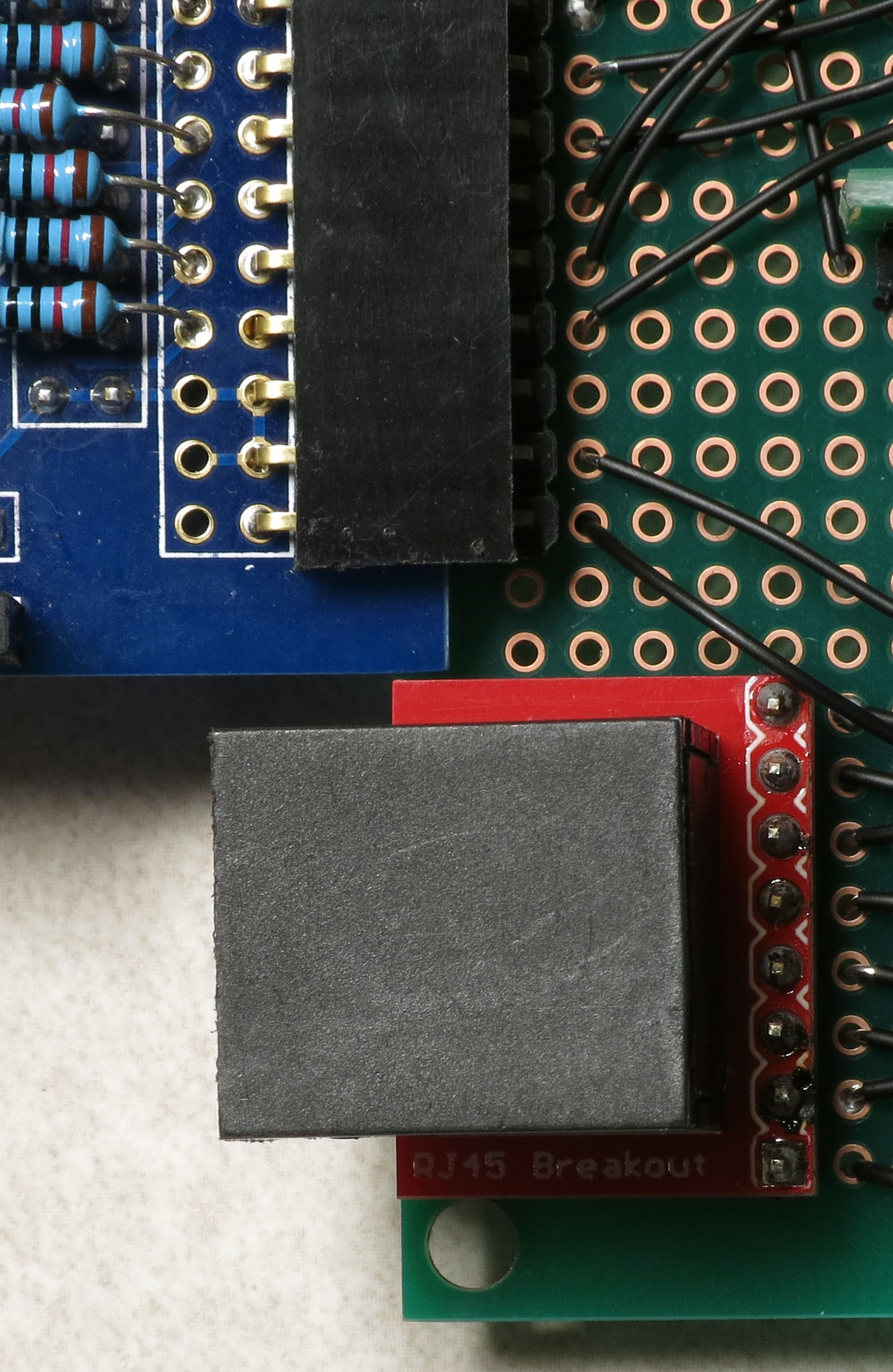
 Solder it into place using the first and last pins.
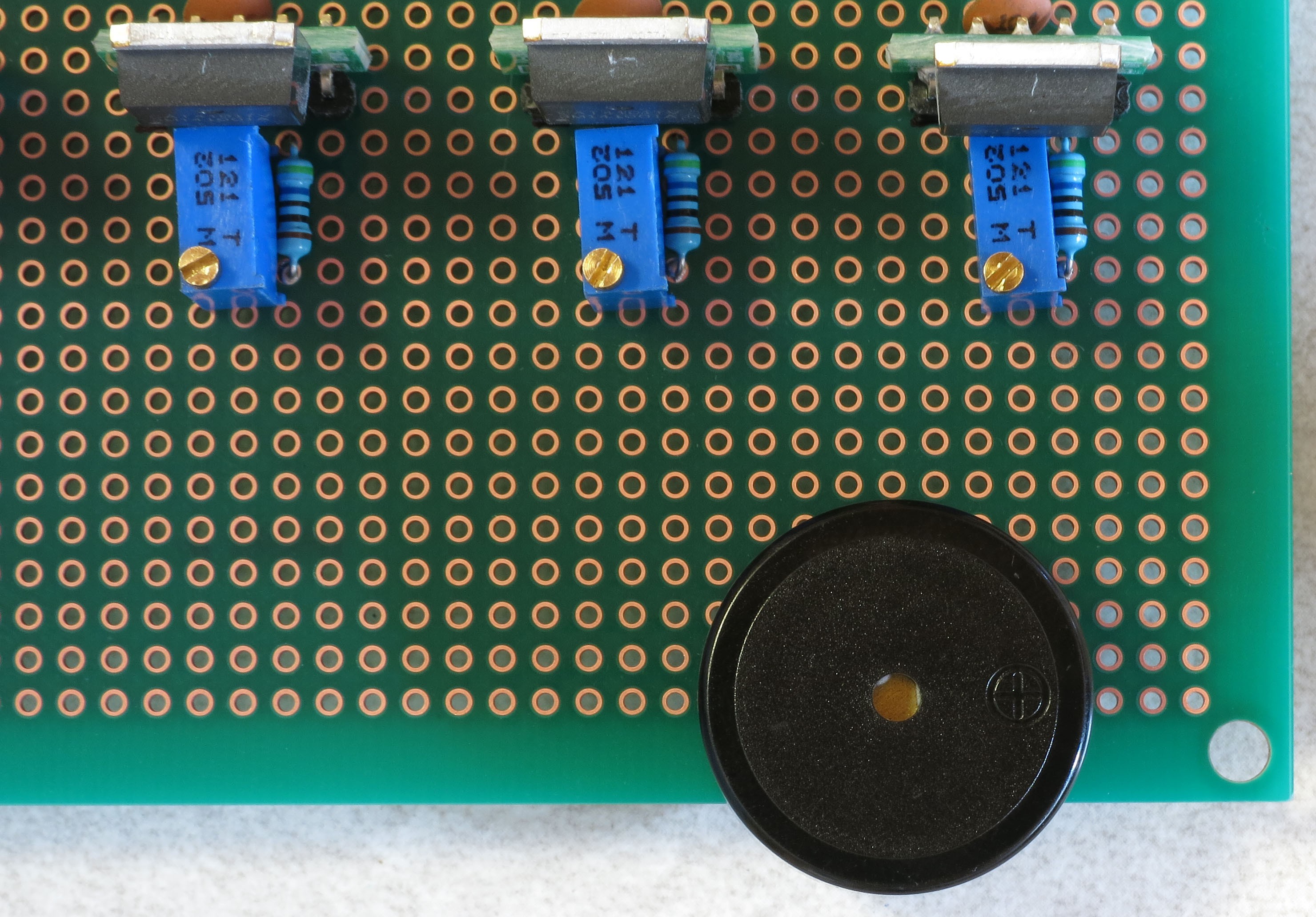 Now break off a strip of 5 male header pins:
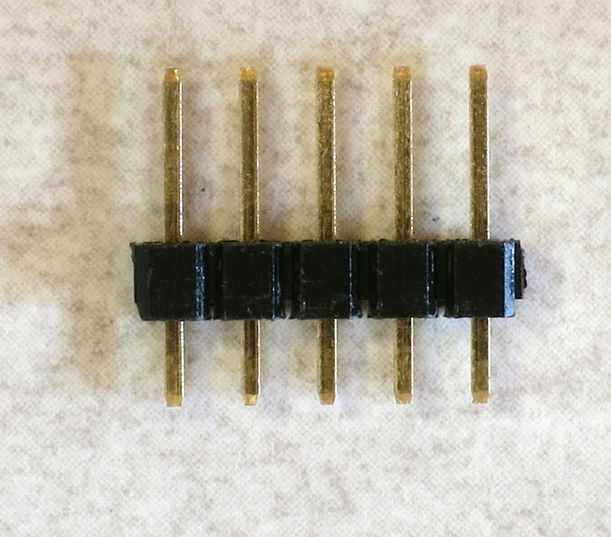 And solder it next to the buzzer (1st and last pins):
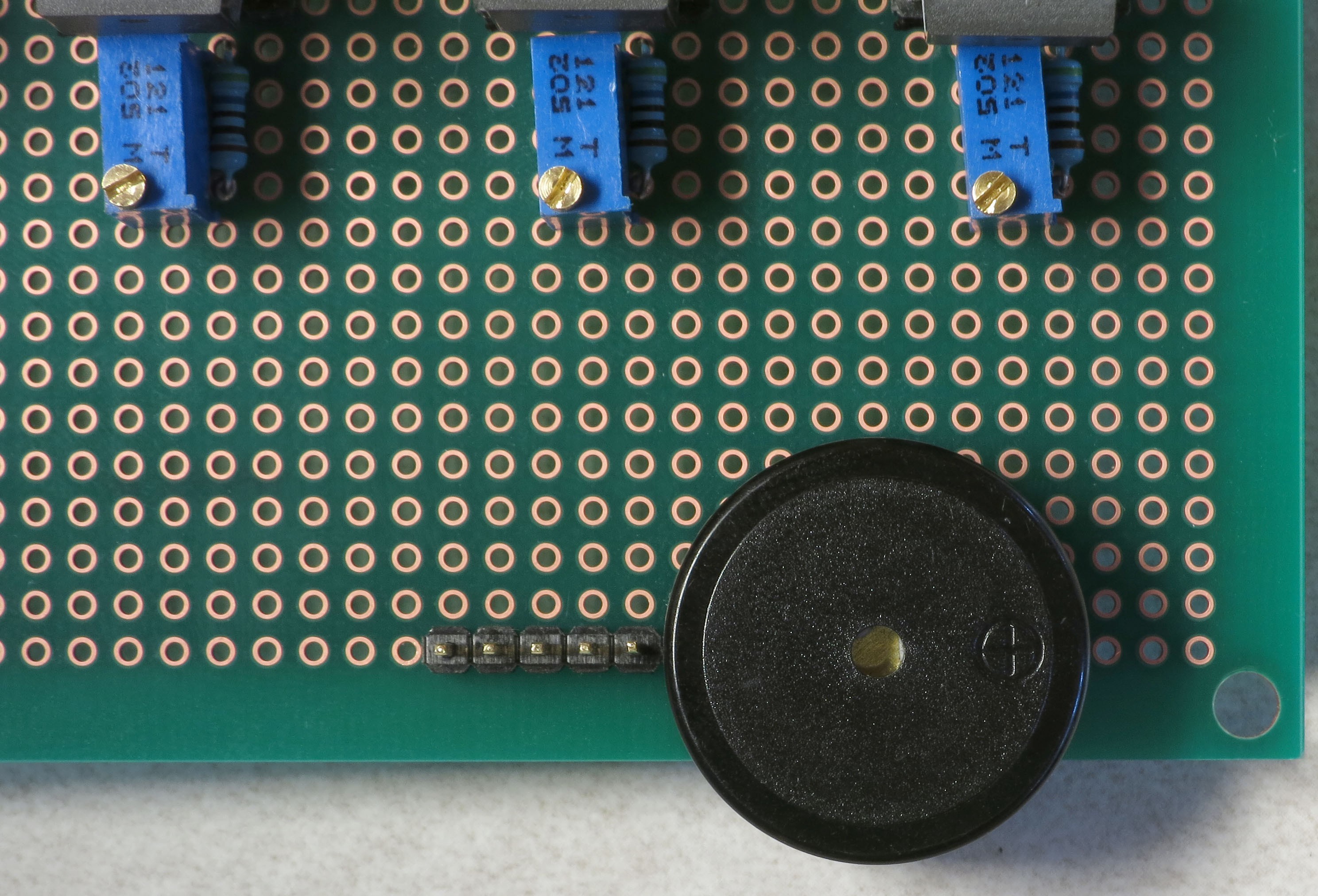 It's a tight fit, but the 5-pin female header on the USB panel connector should still fit (or break out your file again):
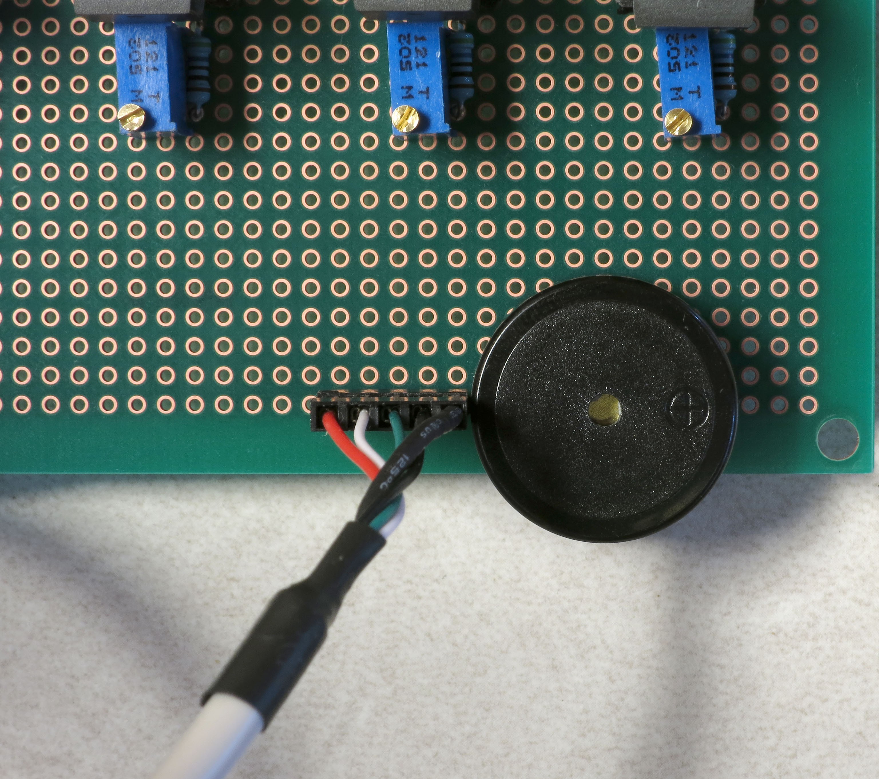 Finally, you'll be soldering a 2-pin male header next to the 5-pin header you just did, and a two-pin female header on the middle right of the board, as shown here:
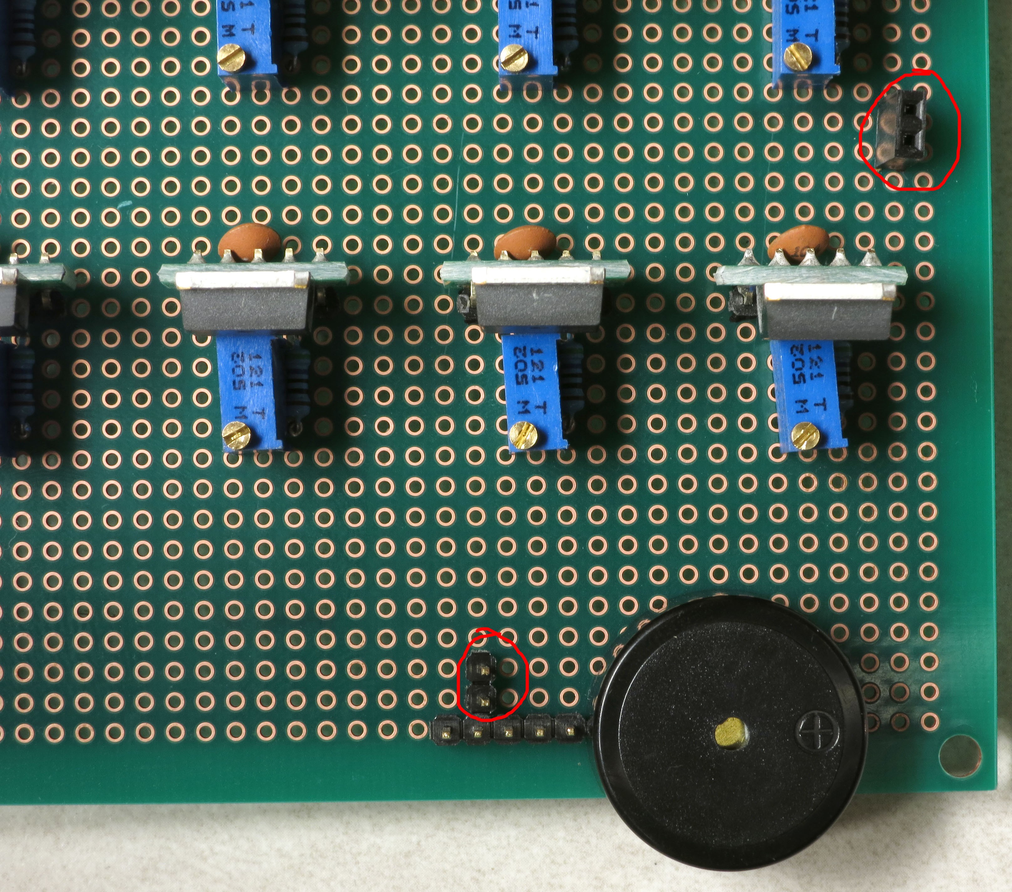 For the male header, use a blob of solder to connect the pins on the 2-pin and 5-pin header that are next to each other. This 2-pin header is for a jumper that will optionally power a servo to fire the camera shutter for those cameras that don't support remotes. Make sure the solder only touches the adjacent pins, and no other:
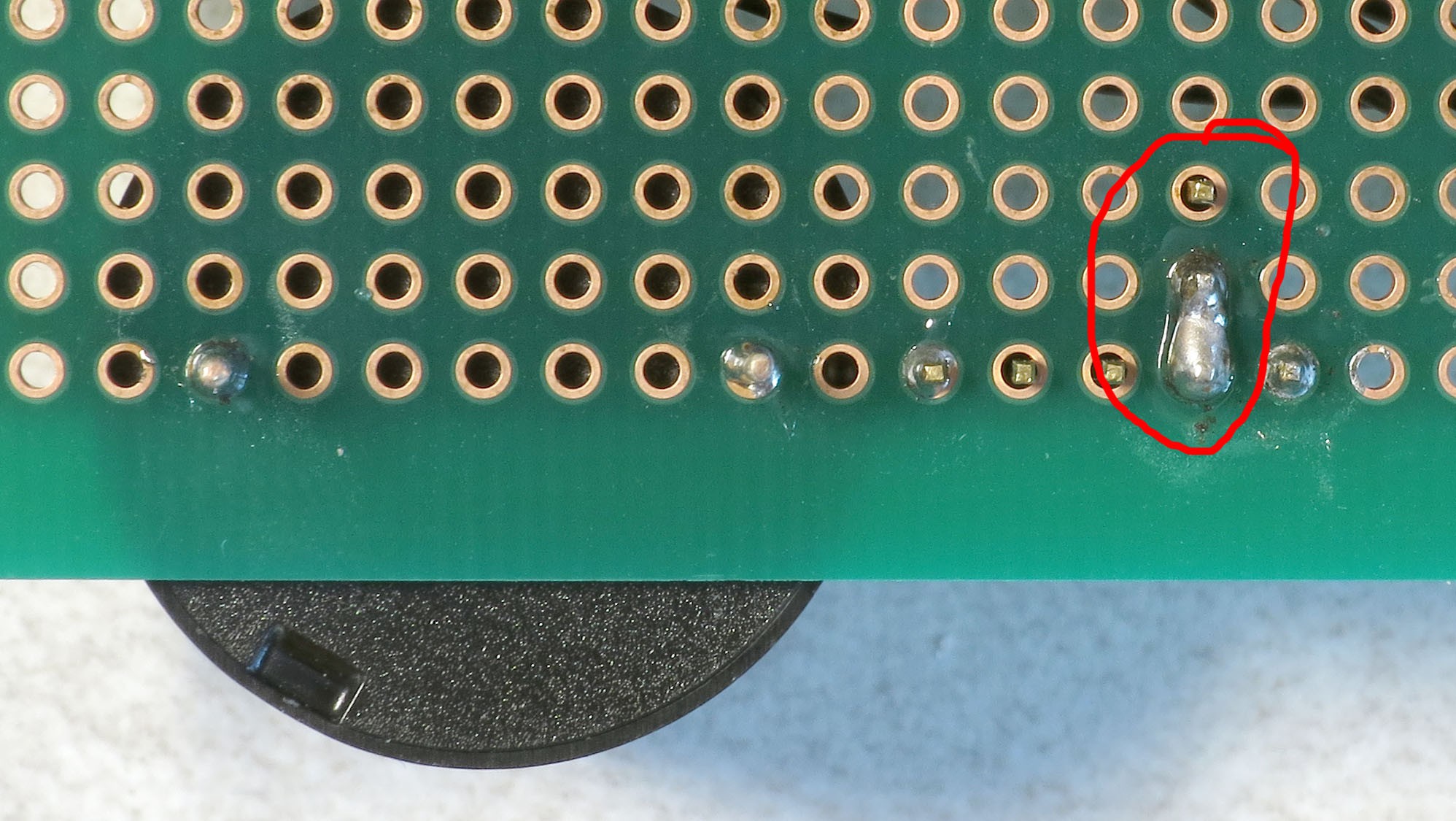

 You don't have to follow the wiring path exactly - it only matters that the matching connections are soldered correctly. Here's how my board looks after that step:
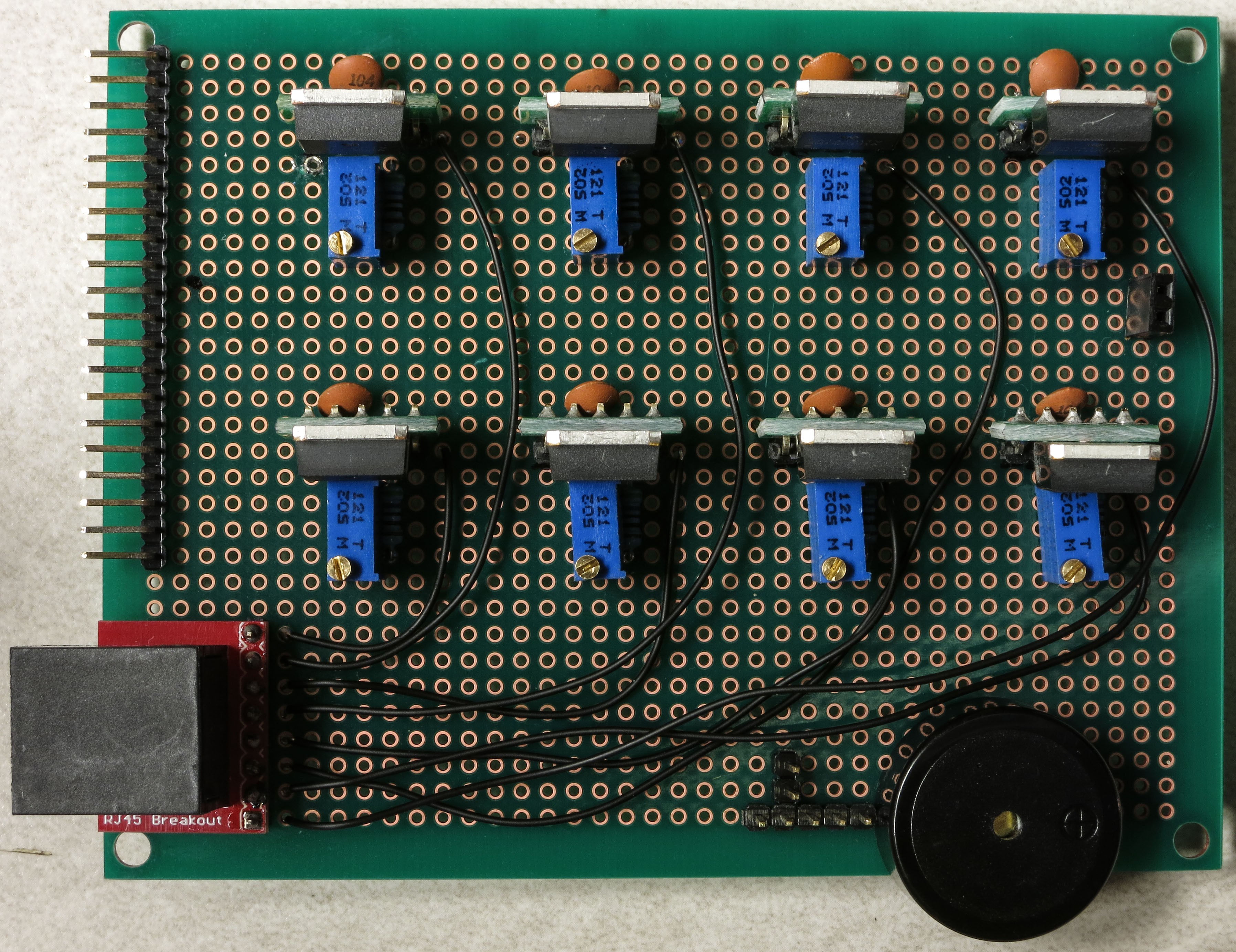 Next step is to electrically connect pins 1 and 2 on the CAT4101s to the corresponding pin on the protoboard connector on the left, which will receive control/power voltages from the Arduino. Since these were already shorted together when you installed the capacitors, you only need to solder the wire to pin 1. You can use the Kynar AWG 24 wire, but if you have thinner wire, you can use that as well, since this connection carries very little current (<20 mA). Here's the wiring schematic; I used a mix of red and white in drawing the wires to make it clearer, the color has no other significance:
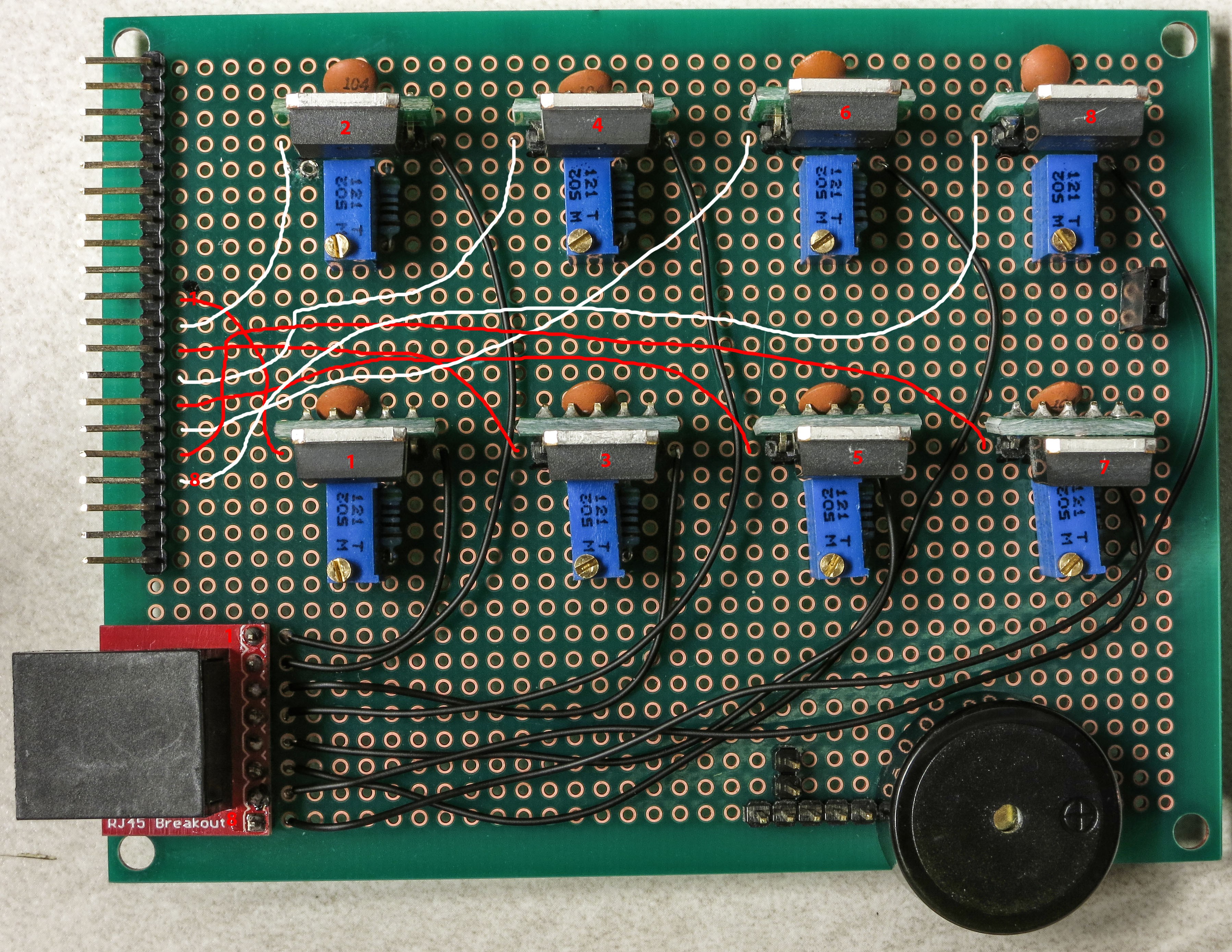

 The 5V power supply for the servo shutter, and the ground connection for both the USB and beeper, need to be hooked up:
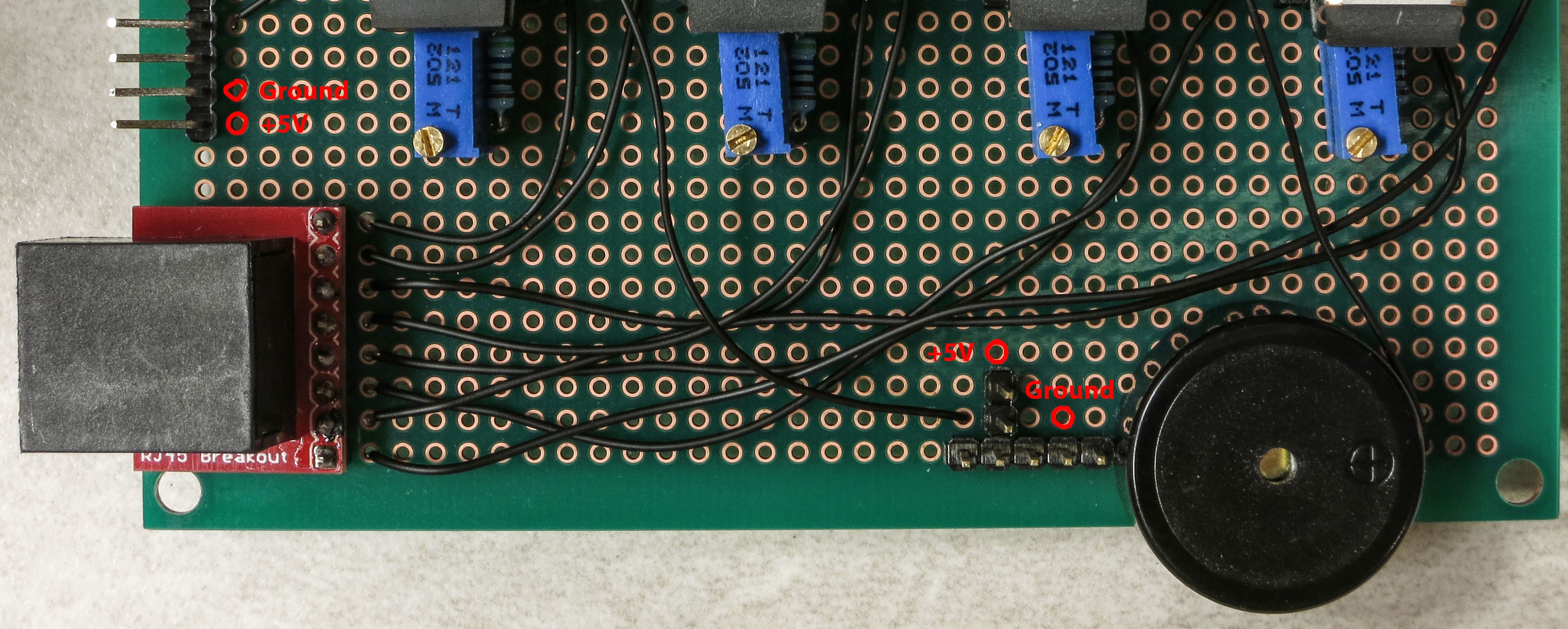
 The ground connection is a bit more complicated, since it needs to be connected to multiple pins. Trim the insulation a bit longer on the right end of the lead, and when you insert it in the specified position, bend it around that fourth pin on the 5-pin male header so that it touches the 5th pin on the header and heads over towards the beeper ground pin. Then bend the beeper ground pin over to make contact with the wire lead. It should look something like this:
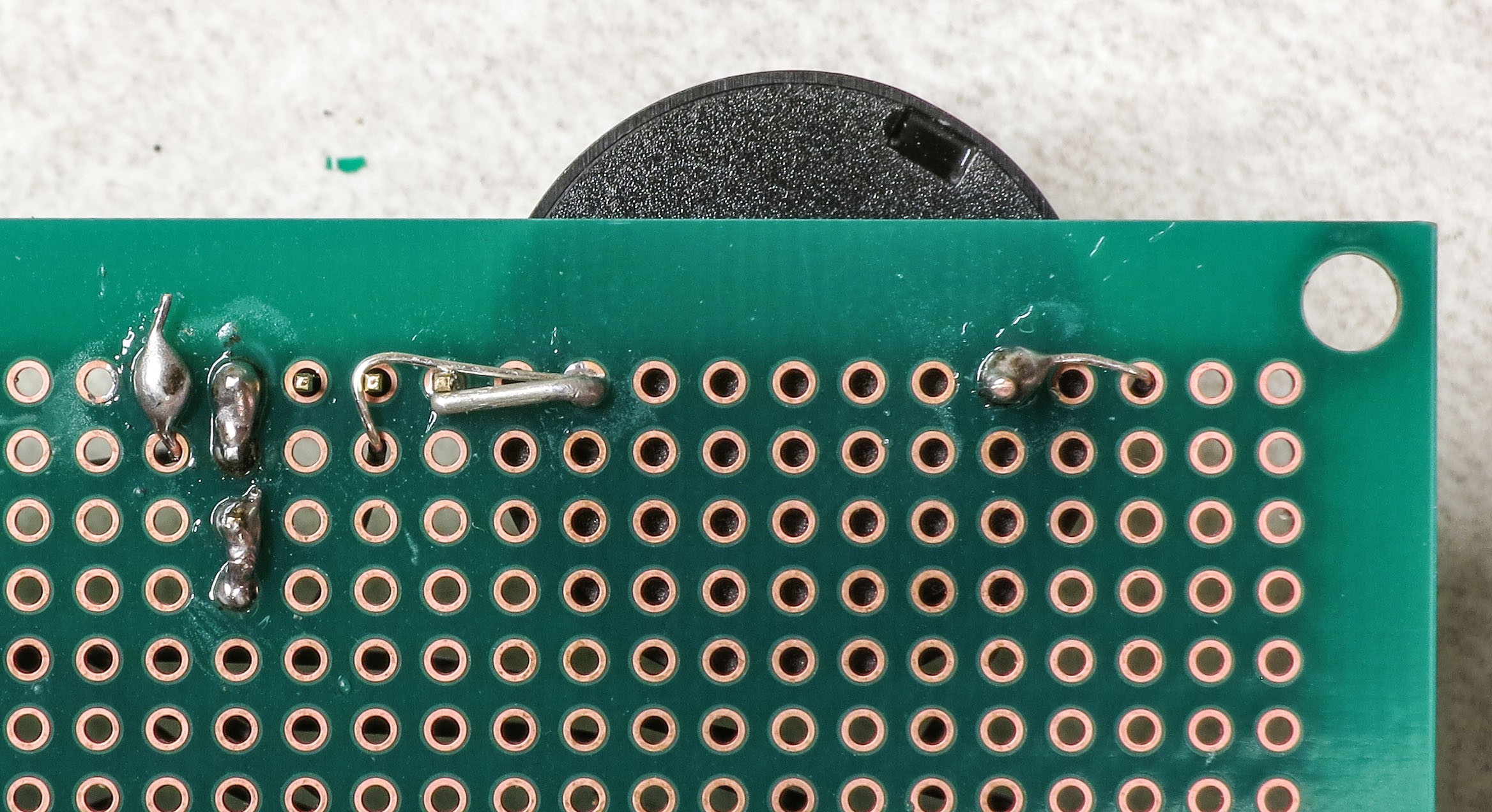
 Check that all the pins/wires are soldered as you see above. On the top side, the board should now look like this:


Discussions
Become a Hackaday.io Member
Create an account to leave a comment. Already have an account? Log In.