-
21Step 21
The RTI system uses an Arduino Mega Board as the system controller, to which you will need to upload various pieces of software for system testing, calibration and control. This section is a quick rundown of what you will need for this, including some special configuration issues.
First, go to the Arduino website (https://www.arduino.cc/en/Main/Software), and download the Arduino IDE (integrated development environment) appropriate for your computer’s OS; there are versions for Windows, Mac, and Linux. Install the software, then run it – if successful, it will start up either with a basic test program or an empty program window.
The Arduino IDE comes pre-loaded with a number of special libraries to support common hardware and software requirements. The RTI-Mage control software uses one of the preloaded libraries, SoftwareSerial, to support the optional Bluetooth HID adapter that triggers camera shutters for those cameras controlled by a PC (e.g. USB microscopes). But there are several additional libraries that need to be installed to support the optional OLED display, and the IR wireless remote shutter capability.
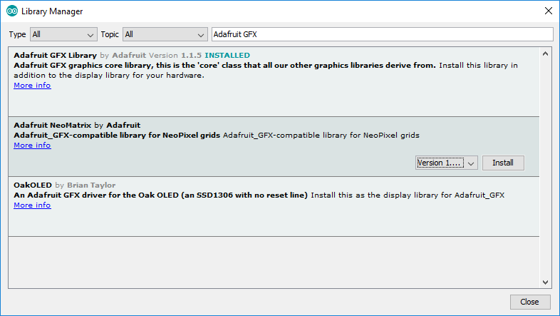
For OLED support, from the software menu select “Sketch -> Include library -> Manage libraries …”. This will bring up the Library Manager screen:
![]()
You want to install two libraries needed to drive the OLED display. The first one is the Adafruit GFX Library, which is a general graphics library, so type “Adafruit GFX” into the search box:
![]()
To install the library, click on the one you want and then press the “Install” button at the lower right. I already have the GFX library installed, so I’ve selected the next one down to show the Install button.
Now do the same for the Adafruit SSD1306 library; this is the actual one that runs the OLED, calling routines from the GFX library as needed.
The libraries are stored in the main Arduino data directory; on my Windows system, this is a folder called “Arduino” located in my Documents folder (not sure where on a Mac or Linux system, but it should be easy to find. There is a subfolder called “libraries” where the critical library files are stored. After installing the two libraries above, you should see folders for both of them.
Now go into the folder for Adafruit SSD1306, and open the file called “Adafruit_SSD1306.h” in any text editor. Near the top, you should see these three lines:
//#define SSD1306_128_64
#define SSD1306_128_32
//#define SSD1306_96_16
These lines specify the display resolution used by the library. Two slashes in front make the line a comment, so for the above lines, the default display resolution is 128 x 32. The 0.96” OLED display in the components list has a 128x 64 resolution, so you’ll have to comment out the 128x32 line, and then remove the comment slashes from in front of the 128x64 line:
#define SSD1306_128_64
//#define SSD1306_128_32
//#define SSD1306_96_16
Save the file, and you’re probably done with that library for now (with one minor possibility that you’ll have to go change one other OLED parameter, but I’ll get to that in a future step).
There’s one more library you’ll need to install, but this one isn’t in the Library Manager. This is the “multiCameraIrControl” library written by Sebastian Setz, and available here:
http://sebastian.setz.name/arduino/my-libraries/multi-camera-ir-control/
This library is needed to control the wireless IR remote shutter capability of the system, which works with cameras from Canon, Nikon, Sony, Olympus, Pentax or Minolta that have an IR sensor. Download the zip file from the site above, and unzip the folder “multiCameraIrControl” into the libraries subfolder of the Arduino folder. Restart the Arduino program, and that library is ready to go.
Even if you don’t use the OLED or IR capabilities, you should still install the libraries anyway. The program will call for them, and if it doesn’t find them, it won’t compile successfully. You could remove references to them in the program, but much simpler just to leave them in there; even if the OLED and IR hardware isn’t installed, the Arduino won’t care.
To install a program onto the Arduino, first load it into a program window by selecting it from the File -> Sketchbook menu. Connect your Arduino Mega to a USB port on your computer; if it’s the first time, the computer will have to install drivers for it. From the Tools -> Board menu, select Arduino Mega 2560. On the Tools -> Port menu, once the Arduino has been recognized by the computer, there should be a “COM” port listing for it; select that port to tell your computer where to send the program data.
Once the configuration is done, click on the right-facing-arrow icon near the top to upload the program to your Arduino. Status messages will show up at the bottom, and if everything works successfully, you should see a “Done Uploading” message at the bottom. If you get an error message, double-check to make sure yo
-
22Step 22
Once the adhesive you’ve used to attach the LEDs to the inside of the dome is dry, it’s time to do the wiring that will control and supply power to the LEDs. But there’s a bit of prep work that needs to be done first.
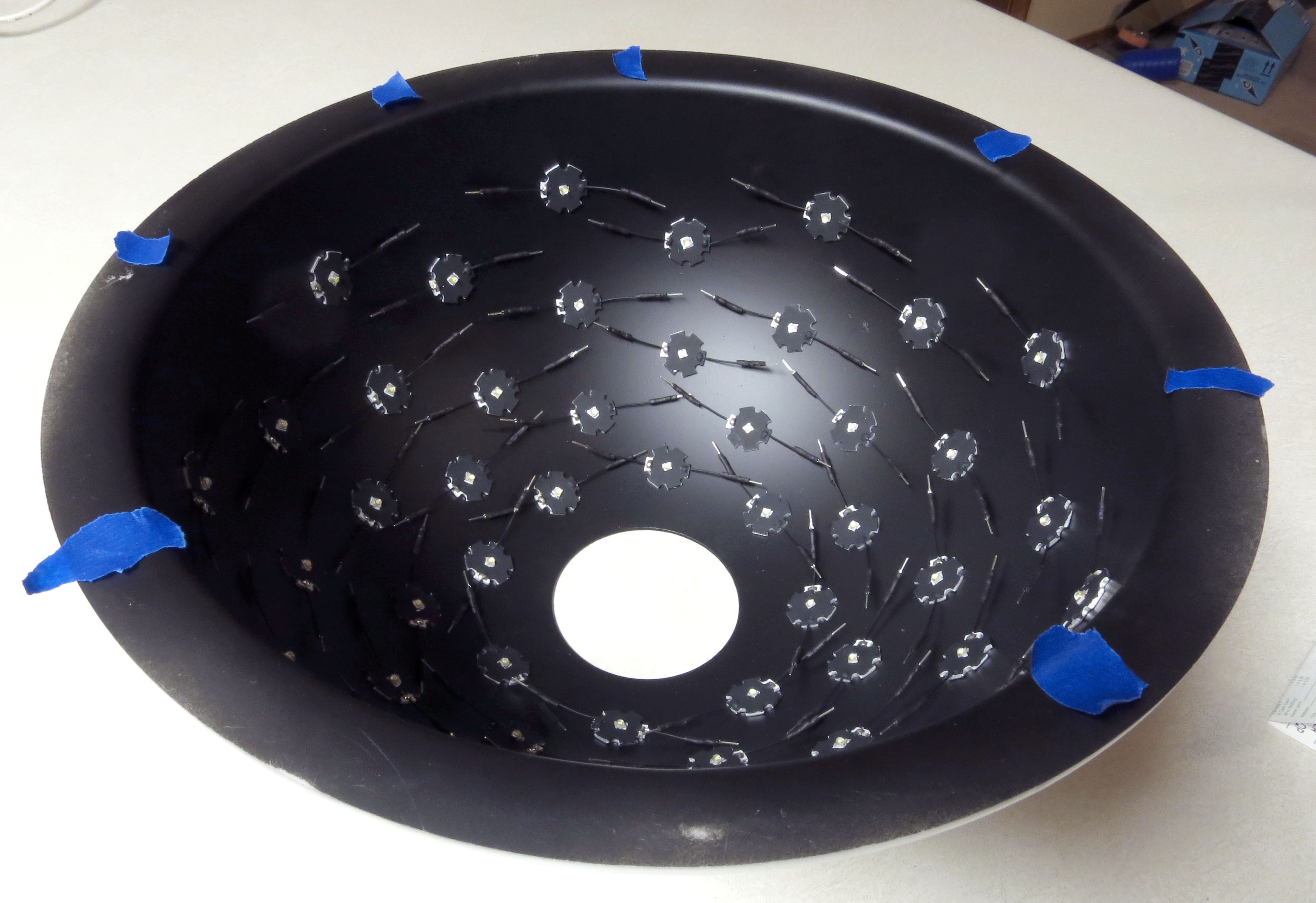
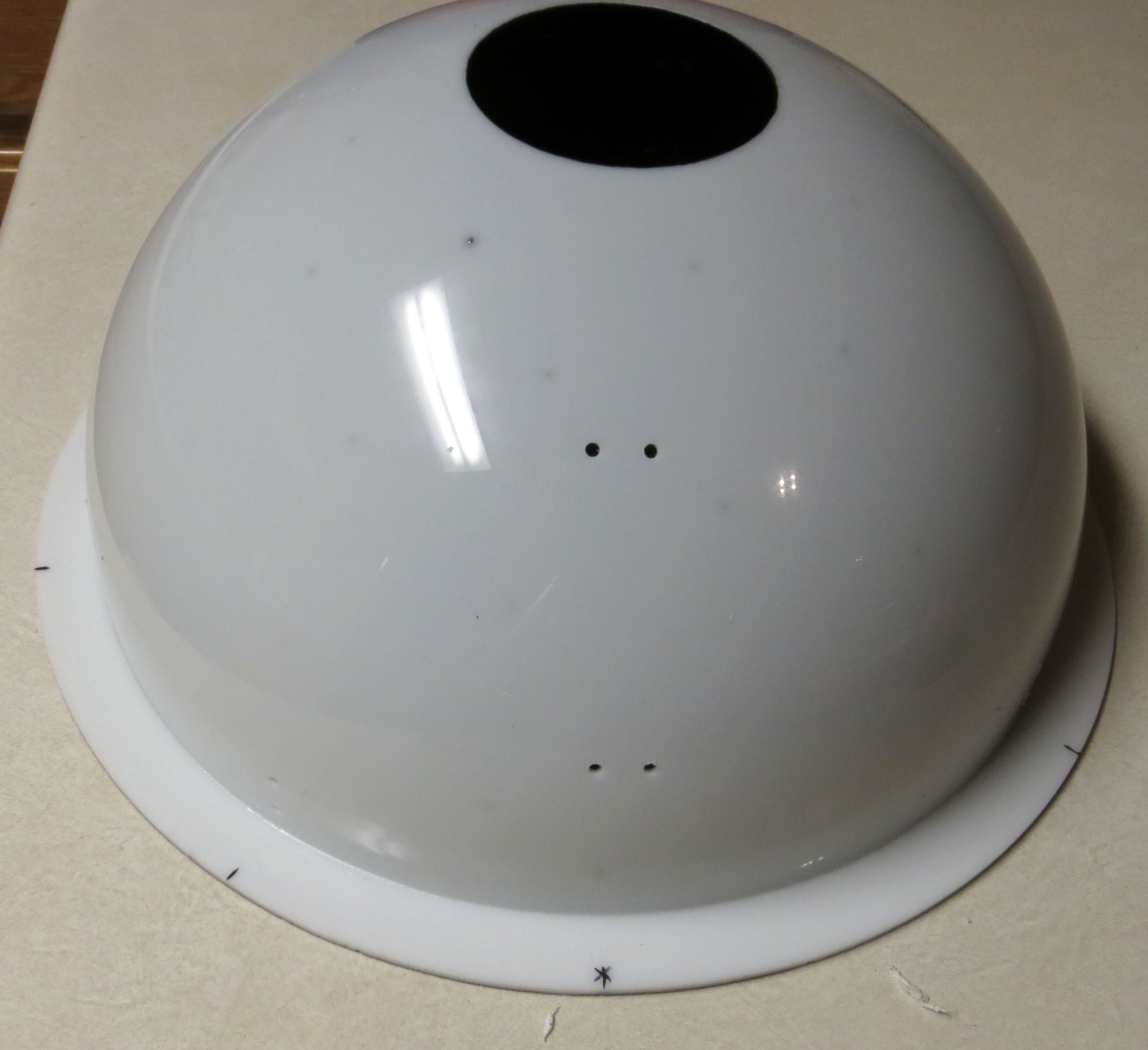
Flip the dome so that the interior faces up, and place a marker (masking tape here) on the bottom of the rim in a position that bisects two of the LED columns:
![]()
As you can see, one of the LEDs in the lowest row (closest to the base) is to the left of the marker, and the LED in the next row up is to the right.That’s actually not a critical reference position, you could wire the dome with the marker to the right of the first and the left of the second. But for now, probably best to follow this convention, since all of the wiring in these instructions (and the pictures) will work off the above marking. Beyond that, pick any pair of columns you want – doesn’t matter.
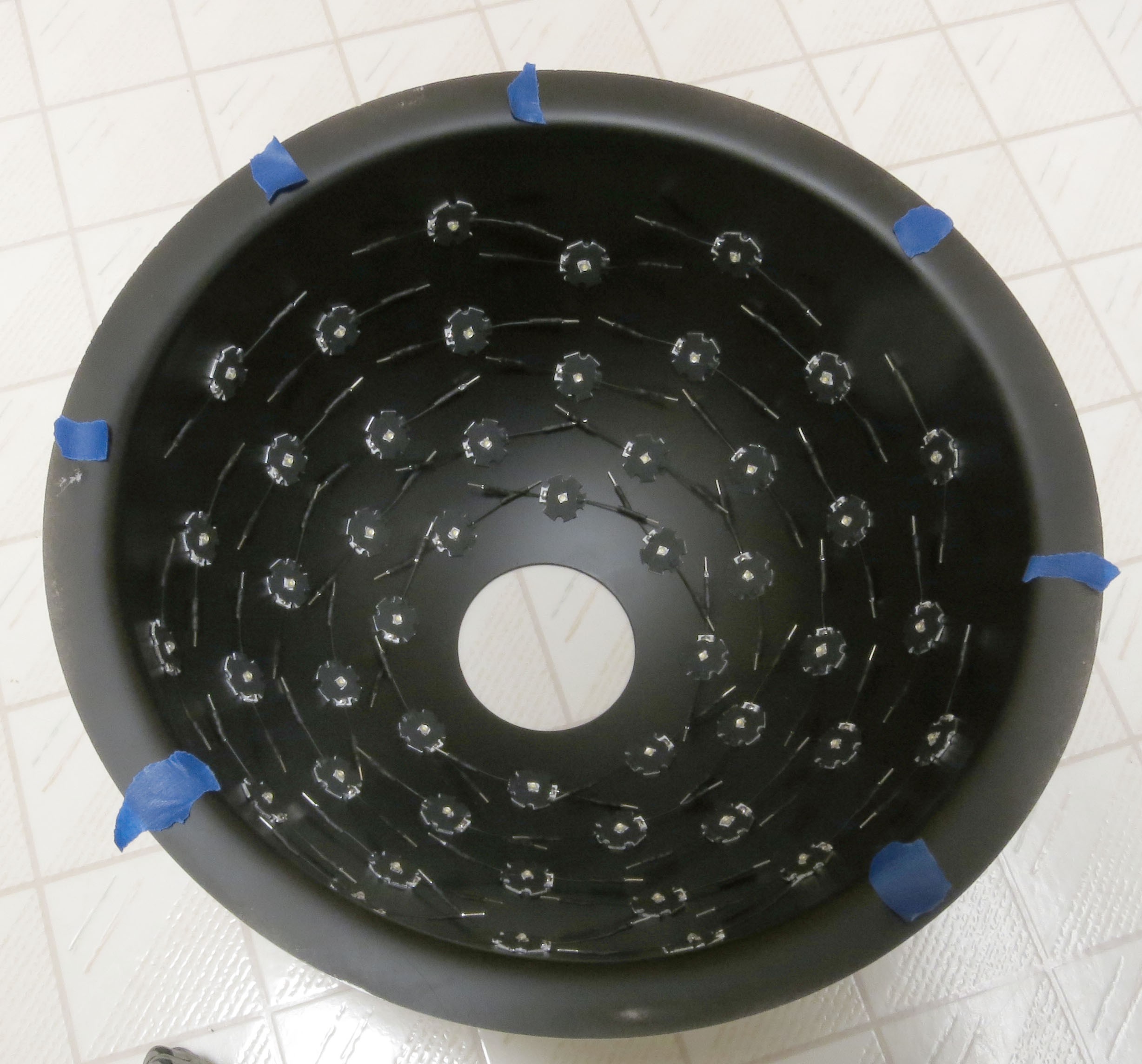
Next, place additional markers on the base of the rim, between LEDs on the lowest row (above those on the next lowest row), three on each side as shown in these pictures:
![]()
![]()
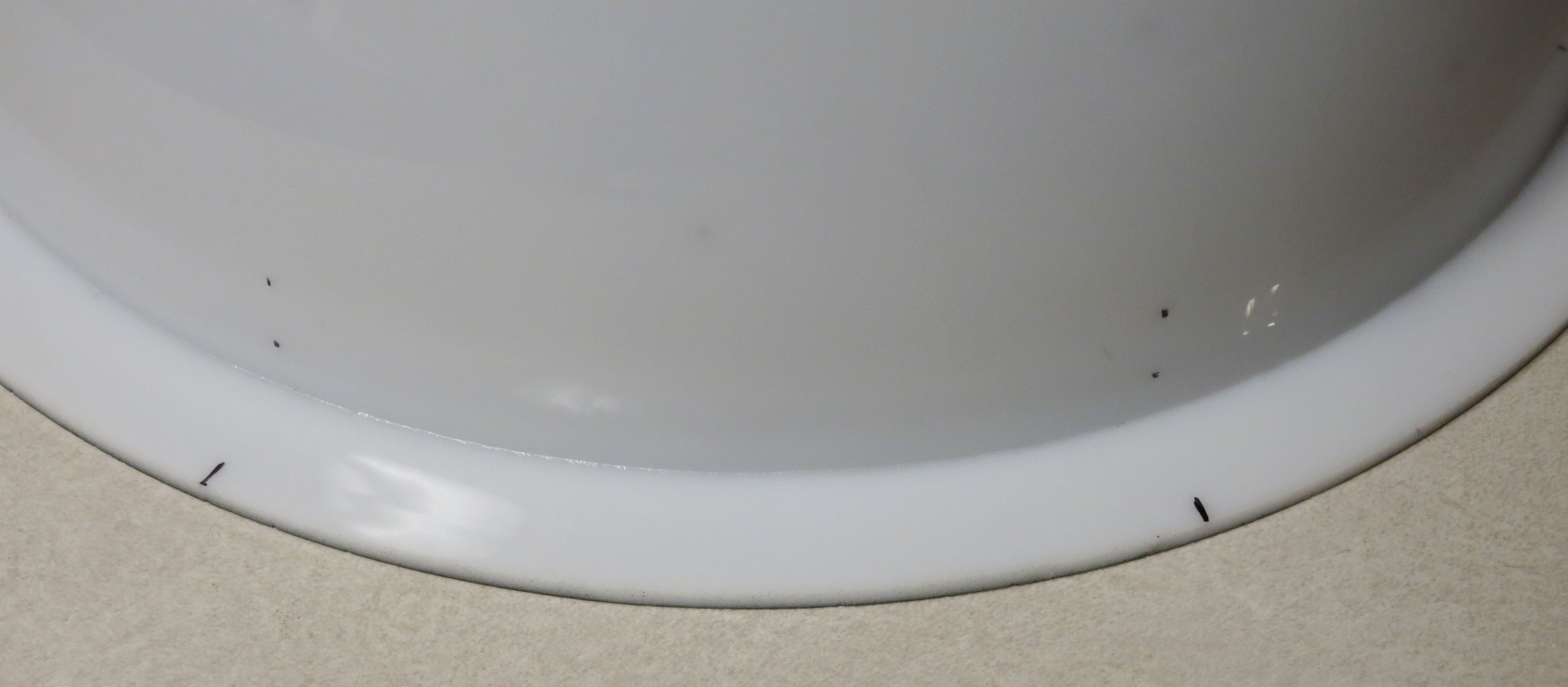
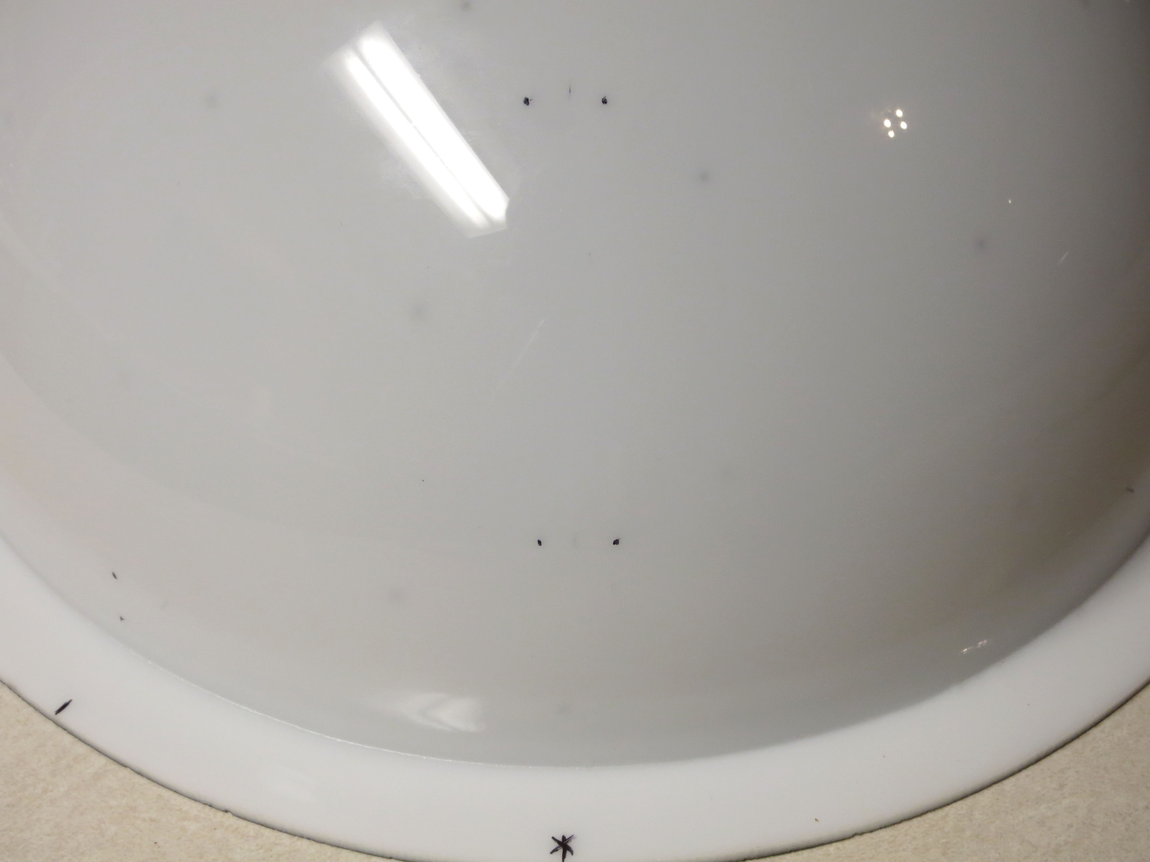
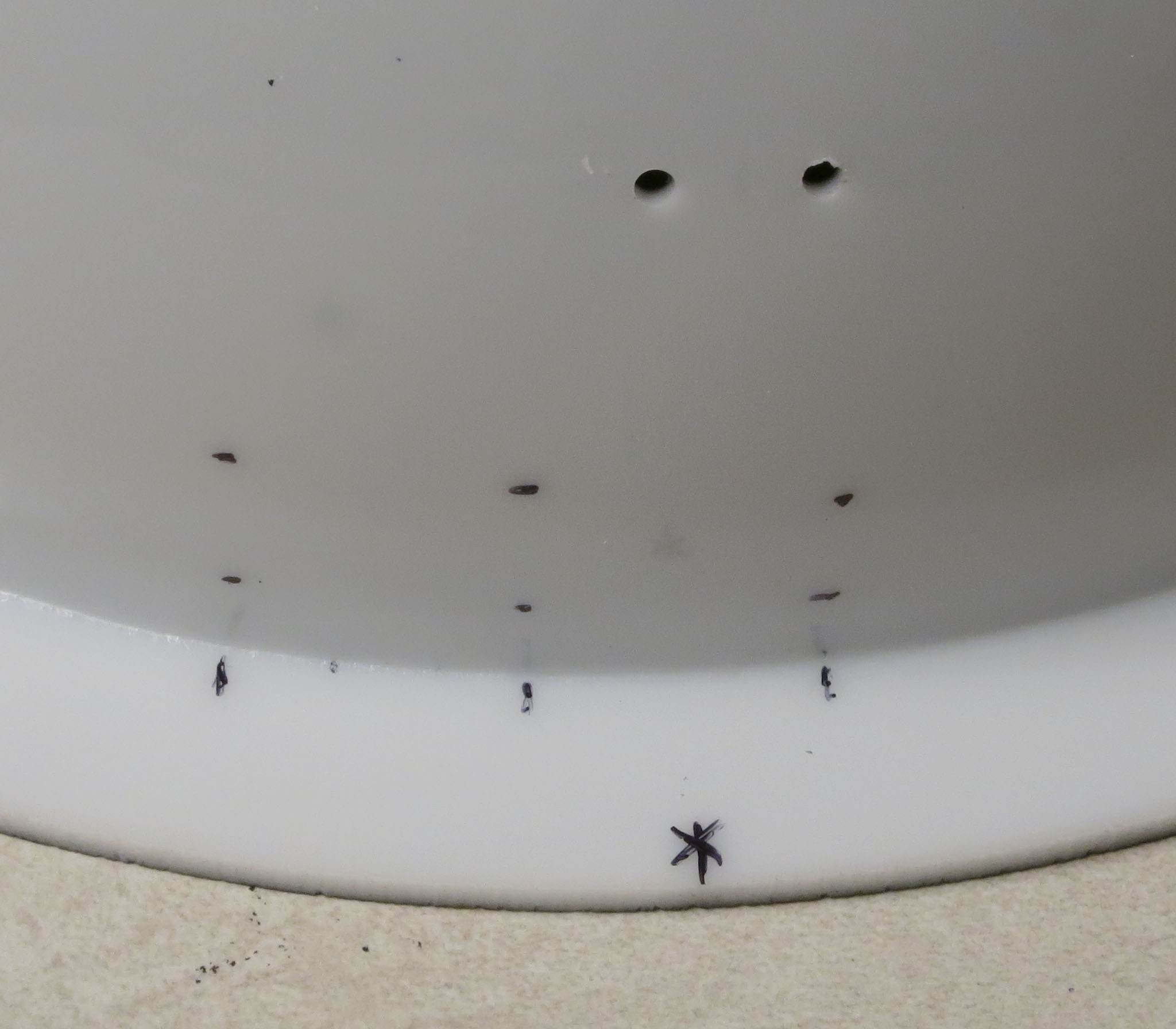
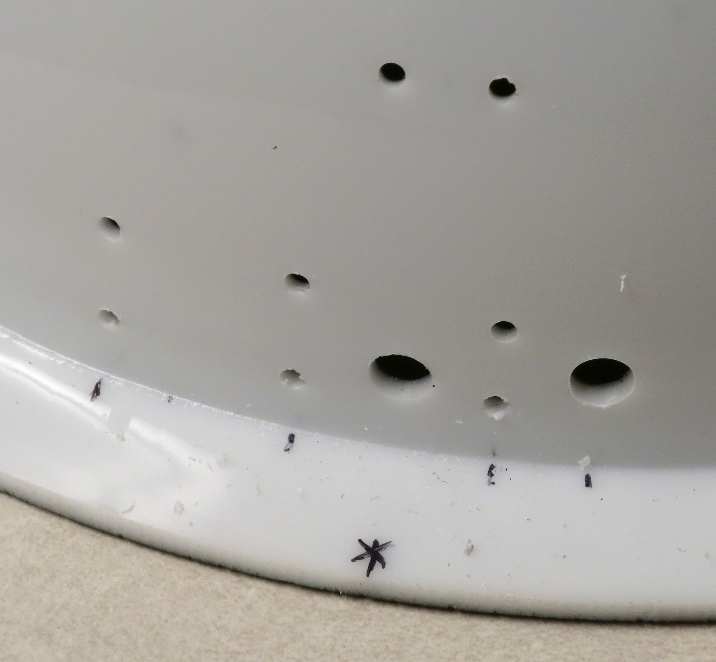
Now flip the dome over, and put marks on the rim of the dome corresponding to the tape marks; doesn’t require absolute precision, just as close as you can. Differentiate the first mark you put down from the rest somehow (an asterisk in the example below):
![]()
For all the marks except the first one, mark the position where you will drill two holes above them, the first about 3/8” above the bottom, the second about ½” above that. These will be for zip ties that will guide and hold some wires in place.
![]()
In the next pic, there will be similar ½”-spaced marks directly above the first reference mark, placed about one-third and two-thirds distance from the base to the top of the dome. These are also for zip tie holes to hold wires in place. However, after finishing the wiring, I realized that these weren’t really necessary for the 12” diameter dome I’m using here, and probably wouldn’t be necessary for any dome up to at least 18” in diameter; the wires are short enough and stiff enough that they don’t need to run through guides to stay in place. So I have those marks in place, and wound up drilling them out, but didn’t install any zip ties through them. For smaller domes you can skip these; for larger ones, I'd probably include them.
![]()
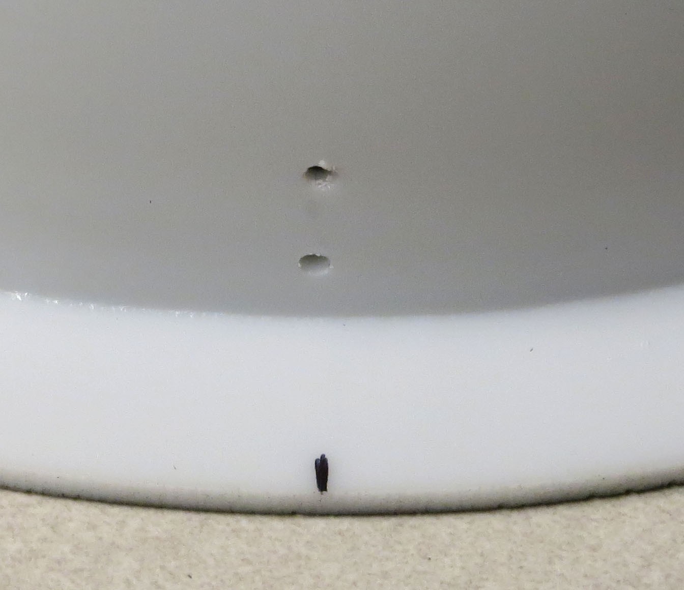
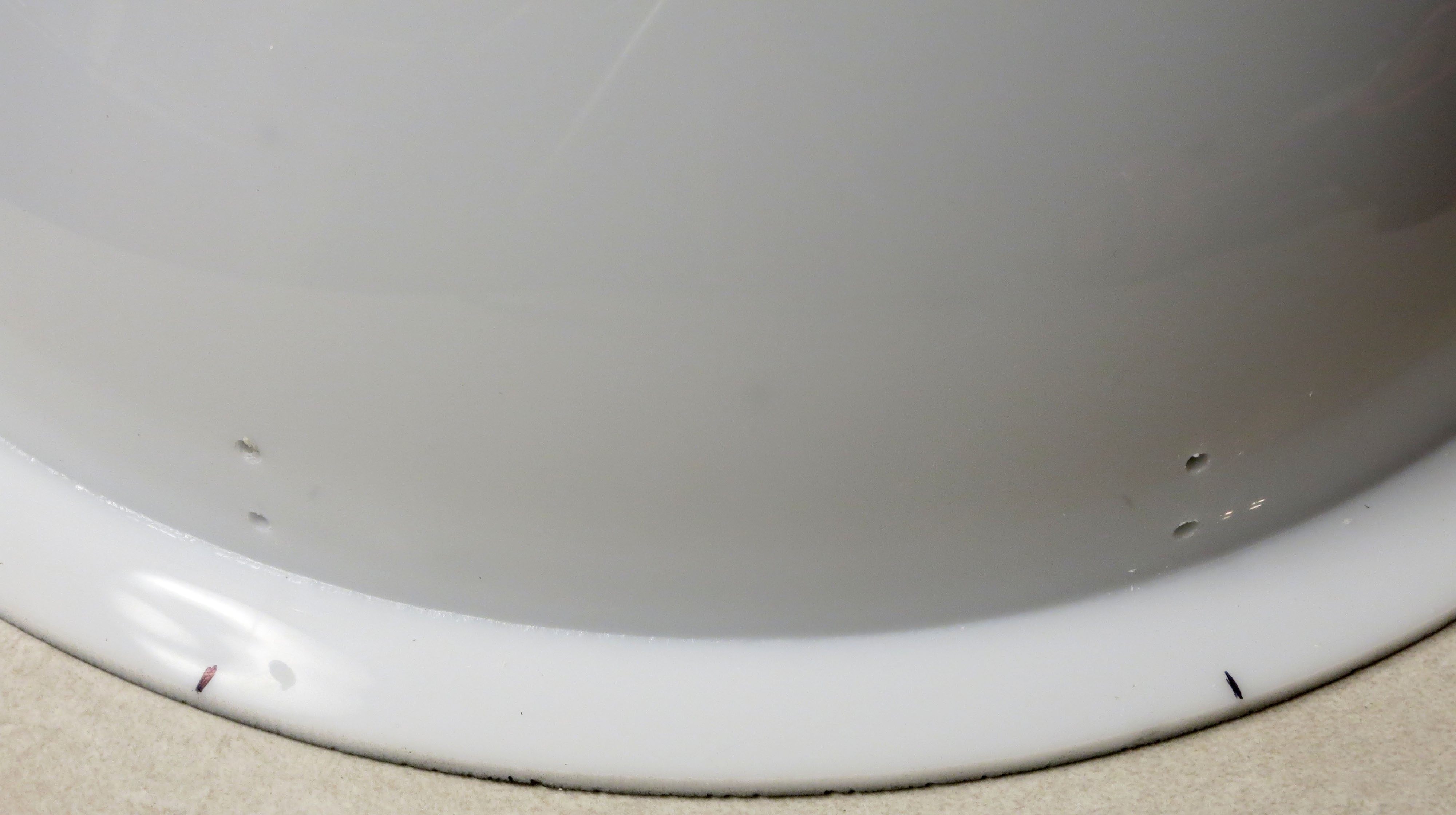
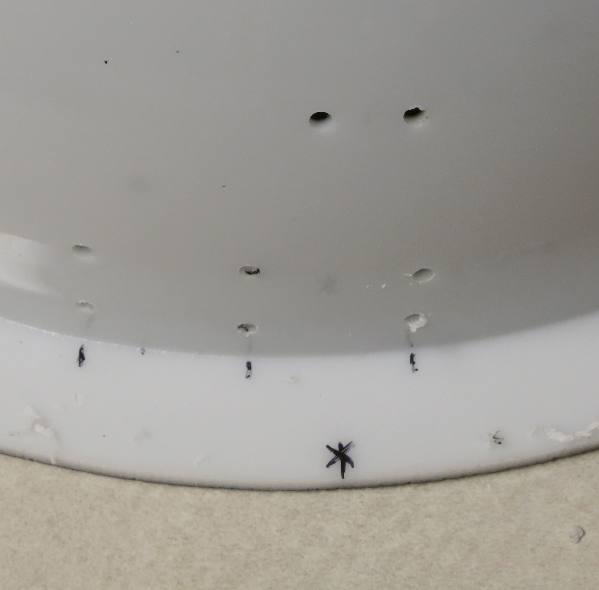
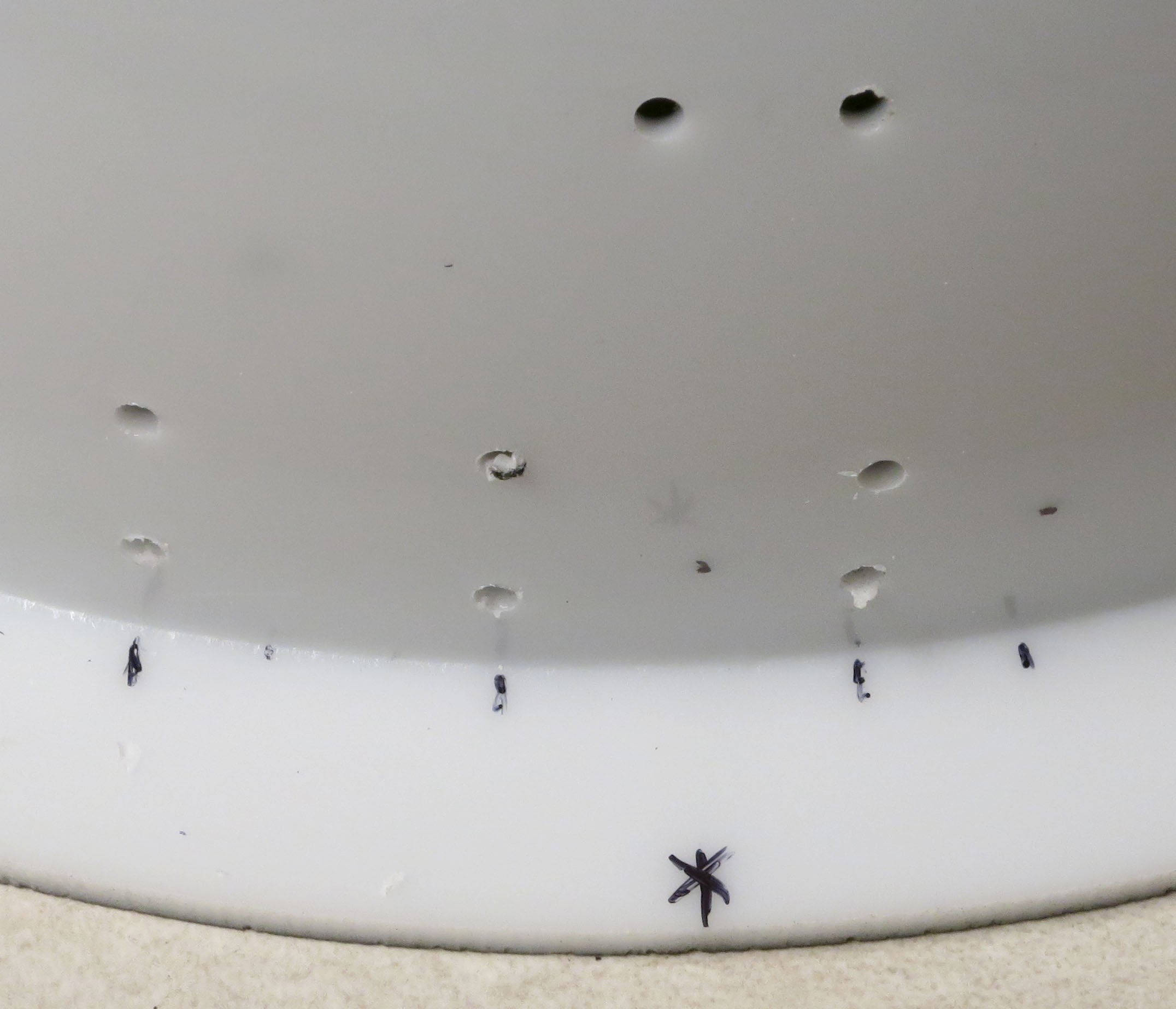
Pull out your electric drill and 1/8” plastic drill bit, and drill holes through the marks you’ve just made. Use lubricant (vegetable oil is fine), and don’t use too much pressure, or you may crack the dome.
![]()
![]()
If you’re building a larger dome that requires vertical wire guides, drill those holes as well (didn’t need them for my small dome, but didn’t know that yet):
![]()
Now mark three additional sets of holes. First, put two marks 3/8” above the base of the rim, 1” apart, centered on the main reference point. Measure about 1” to the left of the leftmost hole, and put another mark there. Then, put two marks about ¾” above the left two marks, and one mark about ½”-5/8” above the rightmost mark. These holes are for zip ties that will hold the power cables in place.
![]()
Drill 1/8” holes with your plastic drill:
![]()
Now mark one position about ½” above the rim, directly above the main reference mark. Put a second mark about 5/8” above the rim, to the right. I have it about ½” to the right of the rightmost holes, but ¾” probably would have been better.
![]()
Drill a 1/8” starter hole at each of these marks, then use a step drill (Unibit) to drill ½” holes at each of these locations; this is where the power cables will go into the dome. The picture shows holes closer to ¼” in diameter, but I found those to be too small and expanded them later on to ½”.
![]() Clean up the debris from the drilling (and the marks you
Clean up the debris from the drilling (and the marks you -
23Step 23
Can’t avoid it any longer – it’s time to wire up all the LEDs in the dome into a matrix configuration, like the one shown schematically here:
![]()
This is an 8x8 matrix, where the rows get connected to ground control, and the columns connected to positive voltage control. For the RTIMage system, the P-channel MOSFETs control the columns/+ voltage, while the CAT4101s control the rows/ground (and also set the current). For the small 12” dome I’m building here, there are only 6 rows, but a full 8 columns, so two of the CAT4101 chips will remain idle with this system.
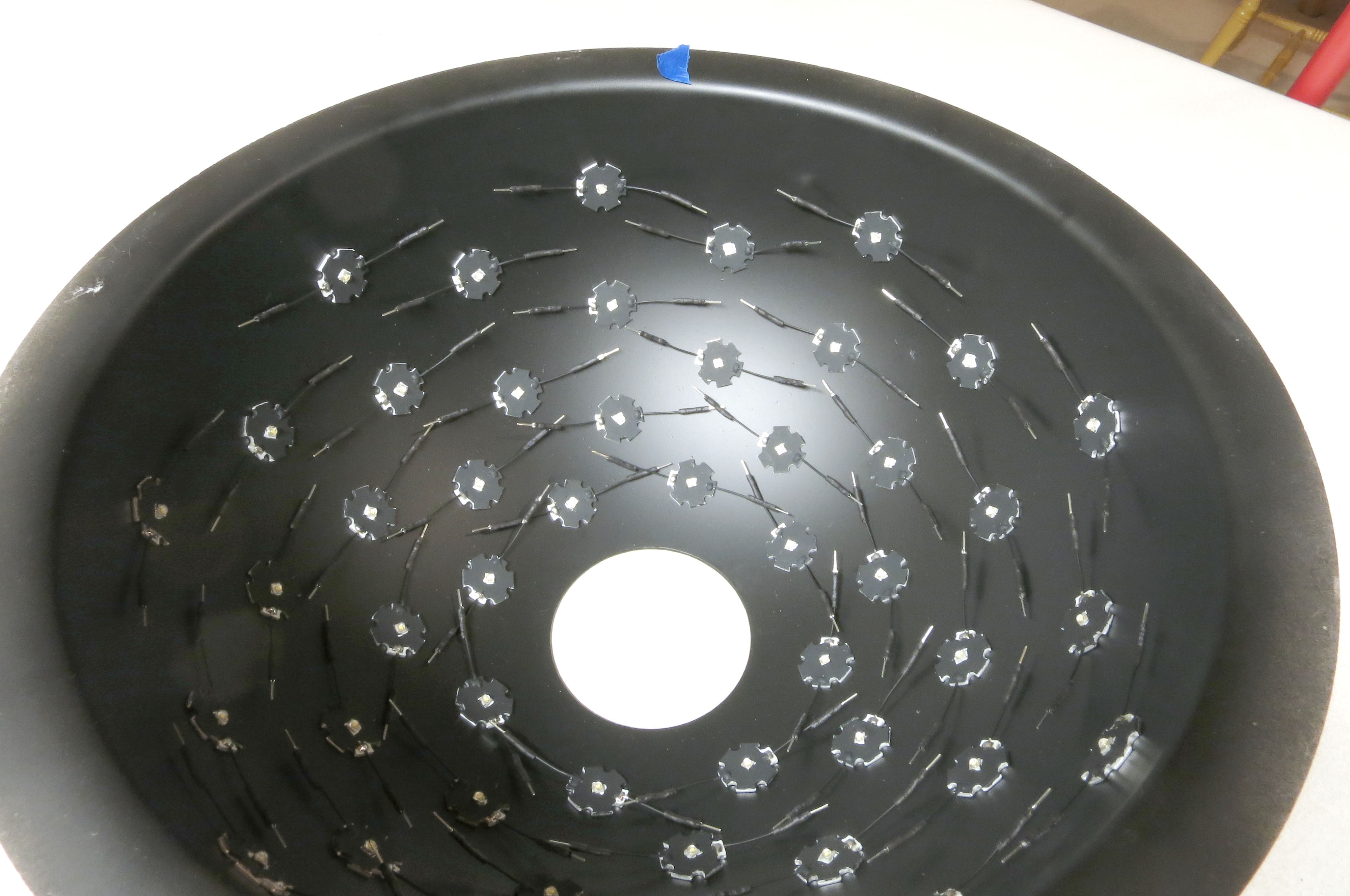
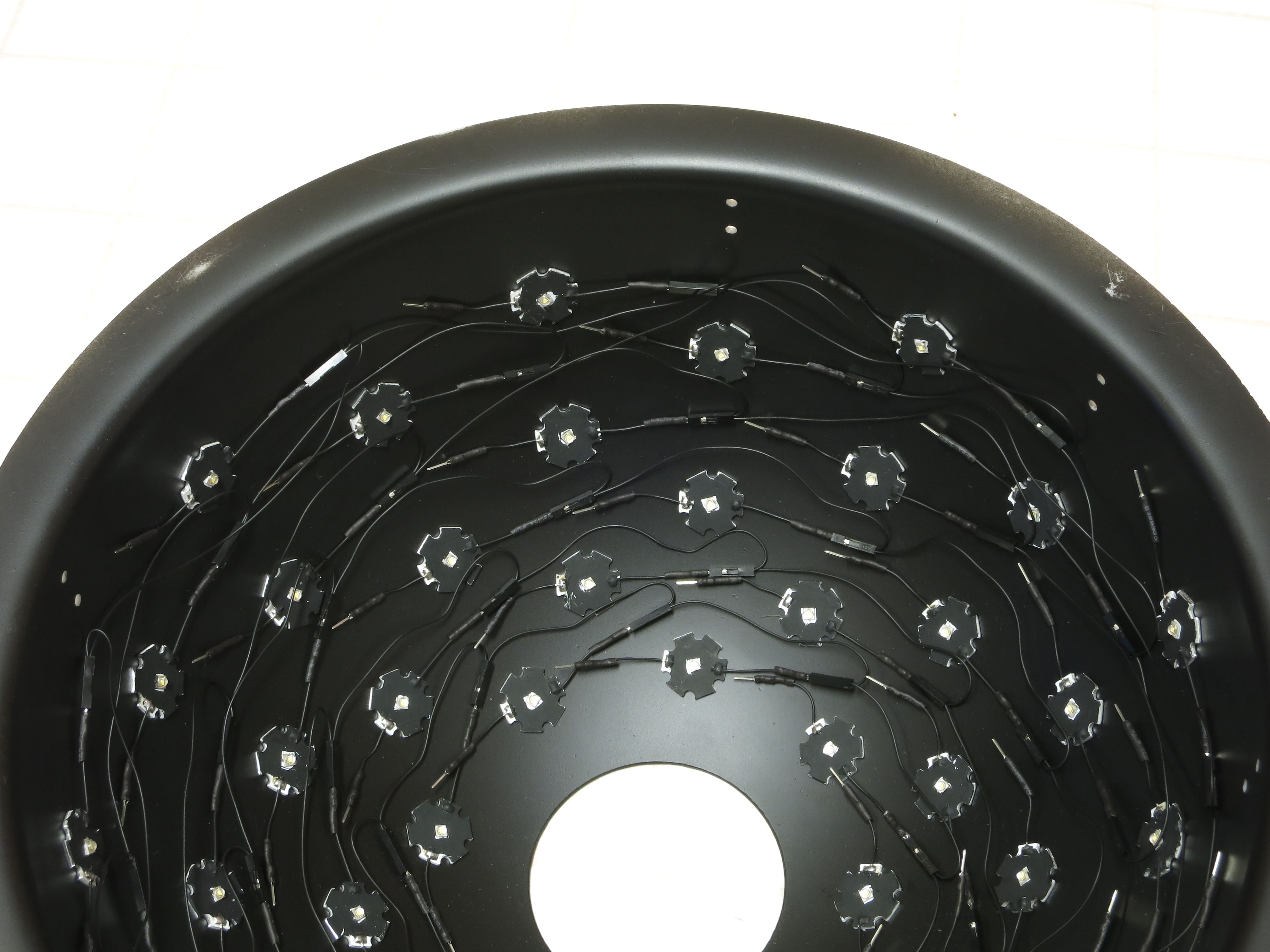
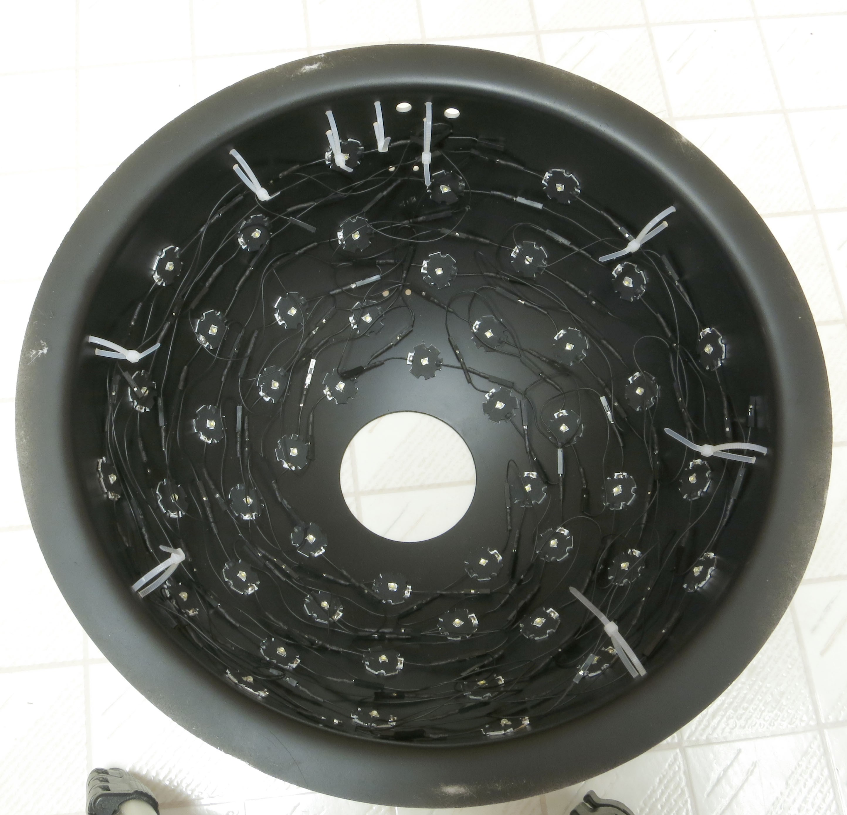
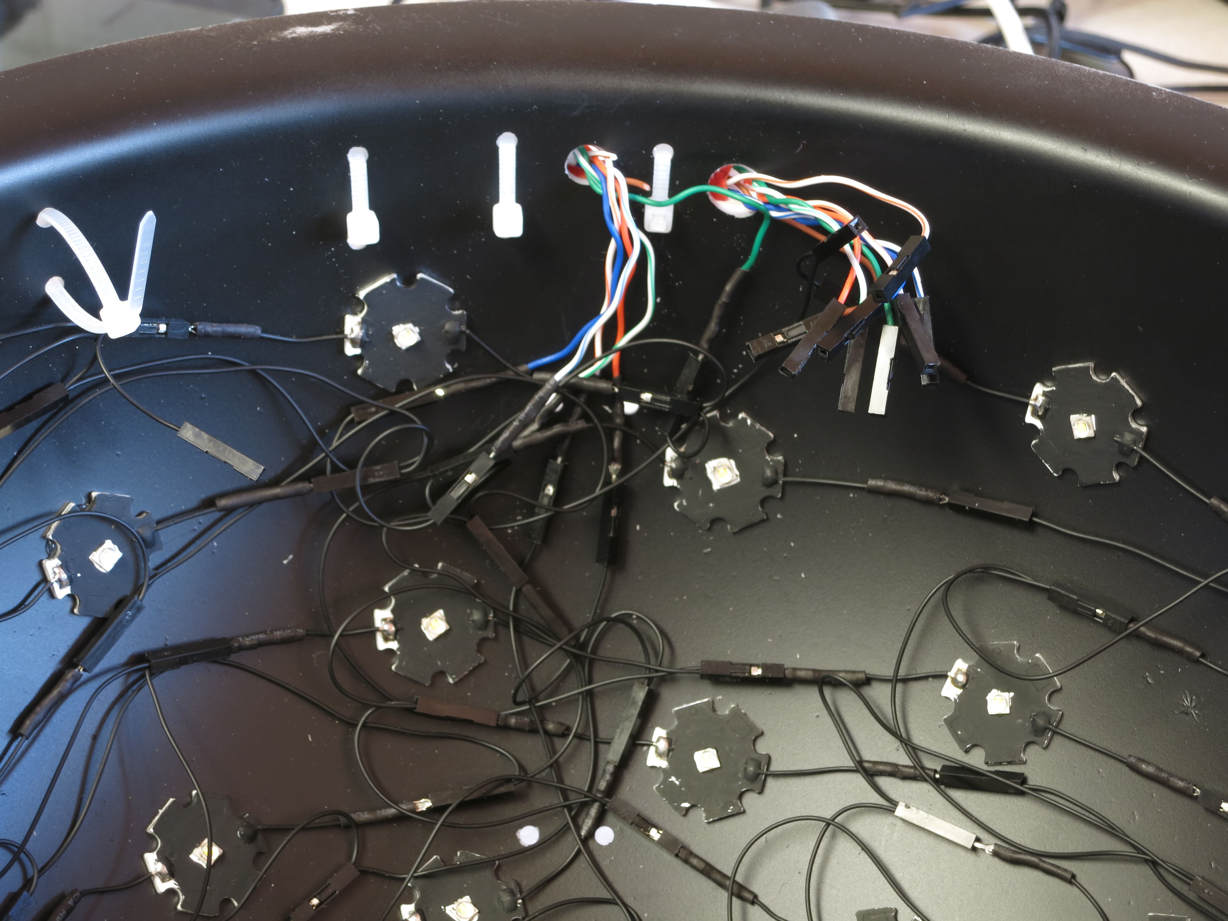
So here’s a shot of the LEDs inside the dome, after being glued in place in a previous step:
![]()
Even with only 48 LEDs, instead of the maximum 64 the controller can support, the prospect of wiring all these up may be a bit daunting. Not going to pretend that this is going to be fun – you’re probably looking at 4-5 hours of tedious work. But I’ve come up with a system that I hope works reasonably well, keeps the pain level down, and lets you fix any mistakes fairly easily. Also remember that this is a small dome, 12” in diameter, so things are packed in pretty tight; with larger domes, there will be more space to work with.
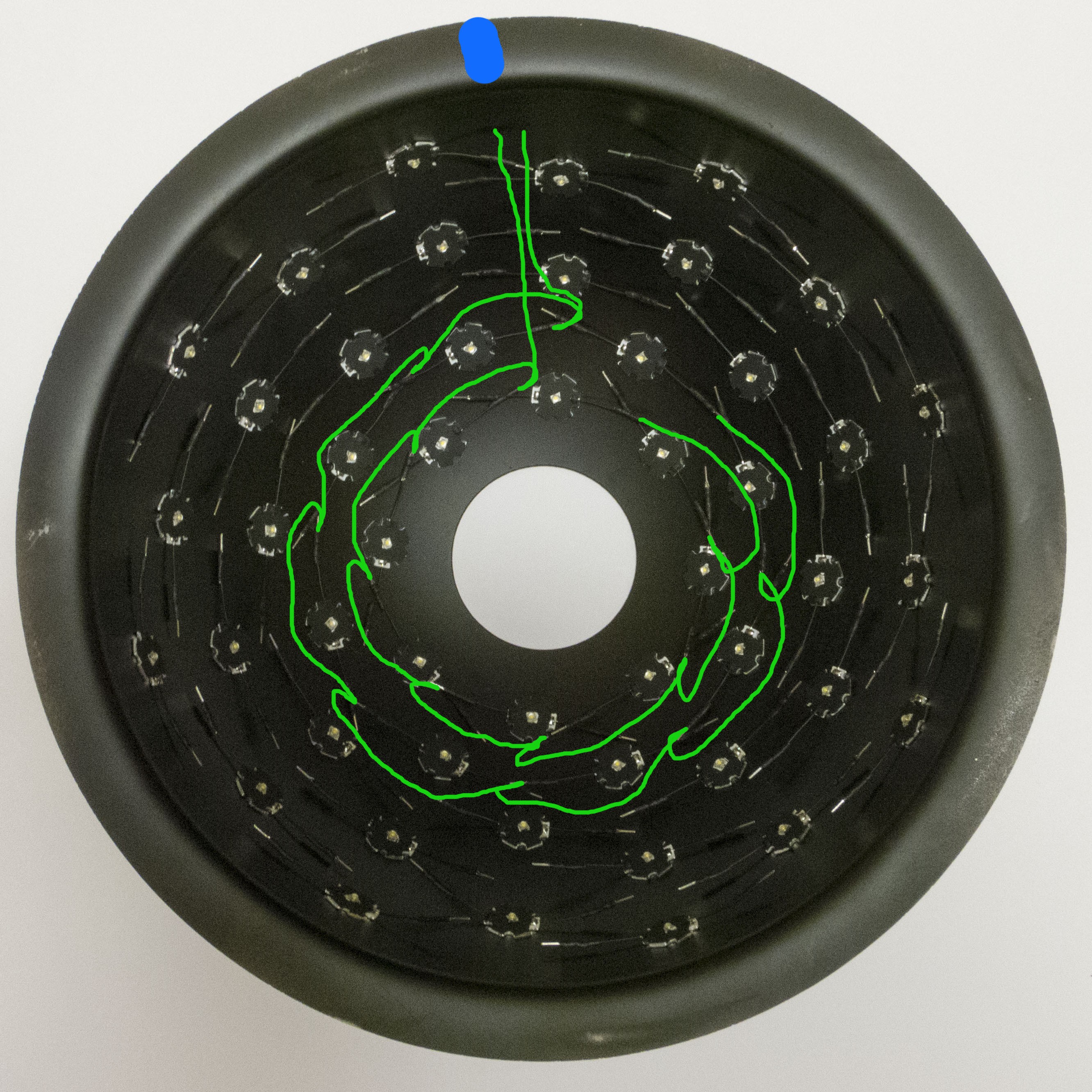
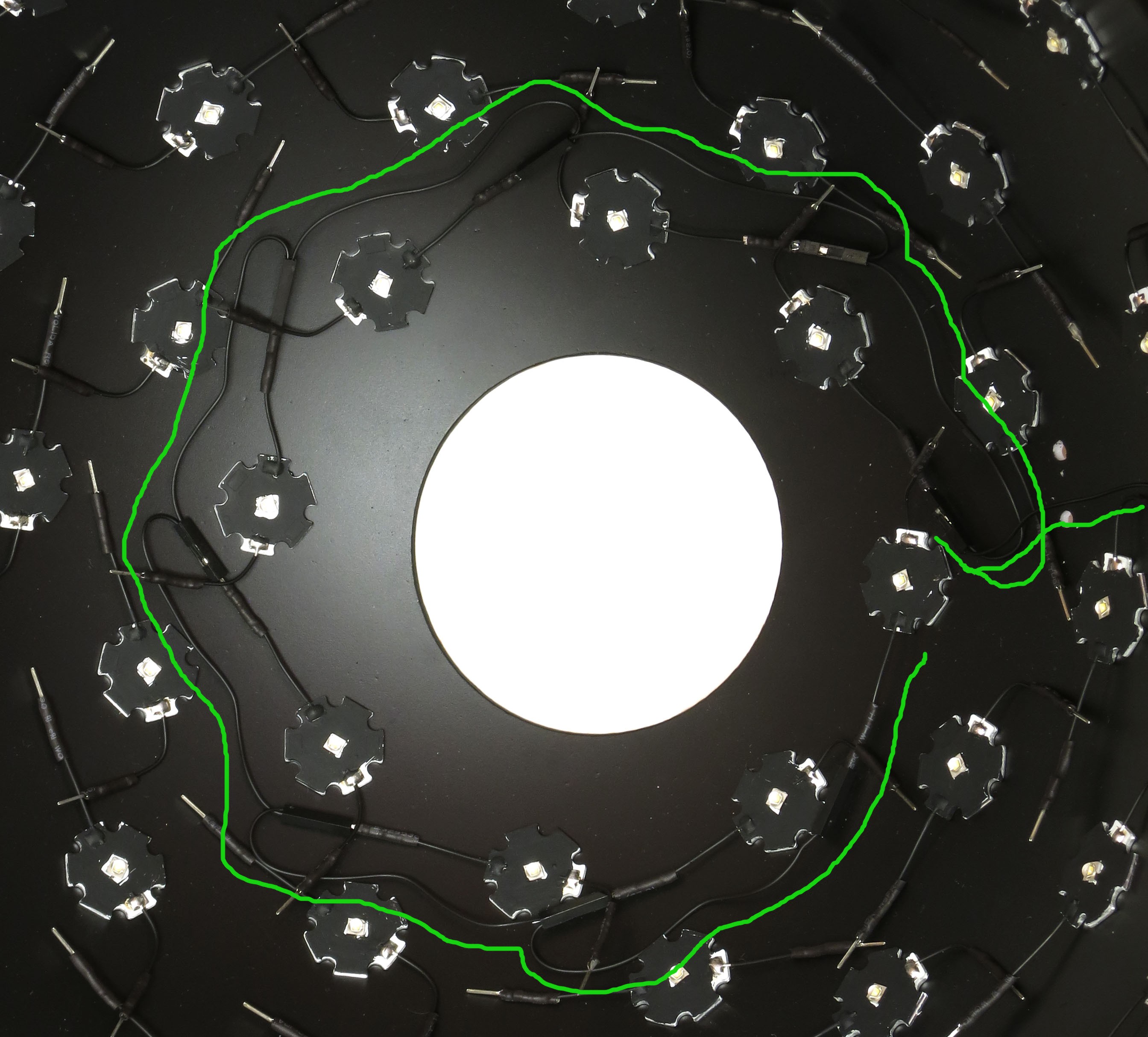
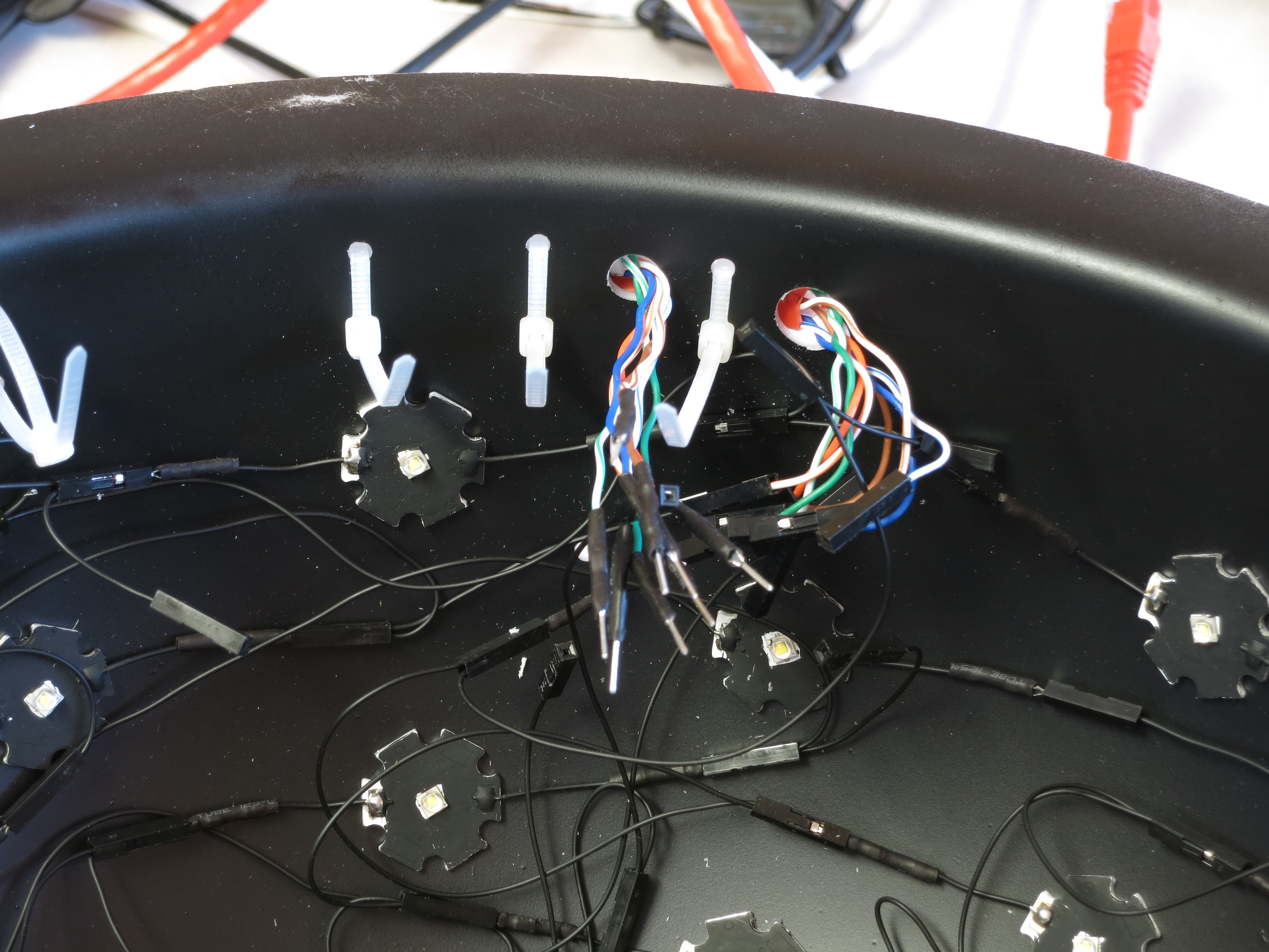
You’re going to be connecting the LED ground leads in a row, and all the LED + leads in a column. Remember that when you painted the LEDs black, you left a little bit unpainted to mark the + side, but painted the -/ground side black, and you can see that above. So you’ll be wiring up the ground rows like this:
![]()
… where the blue mark at the top represents the main reference mark from the previous step. The wiring from only two rows is shown here in green, but all of the remaining rows will be wired in a similar fashion – you connect all the ground LED leads in a single row together, and then the last wire needs to be long enough to reach within about an inch or so of the bottom of the dome.
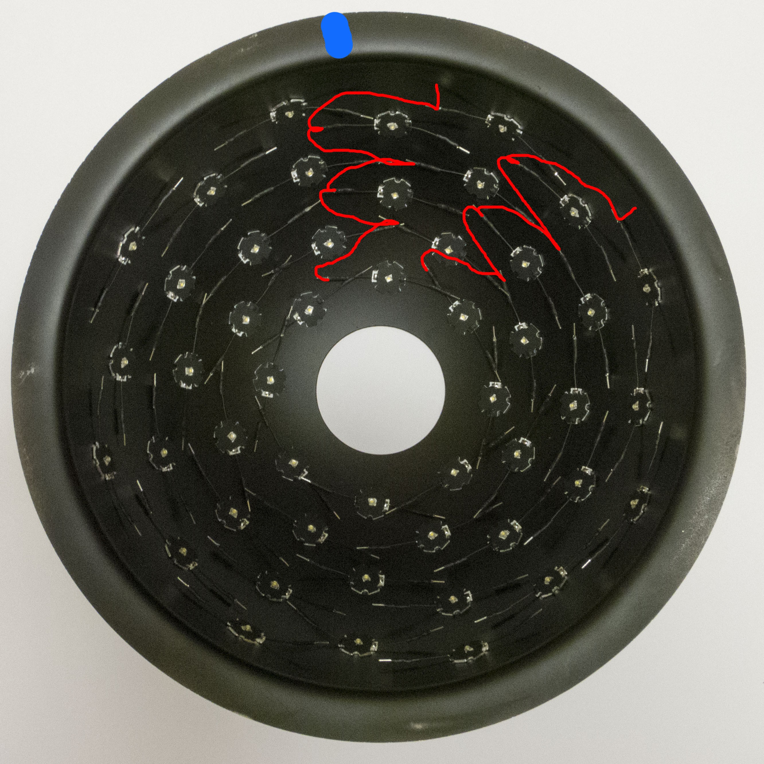
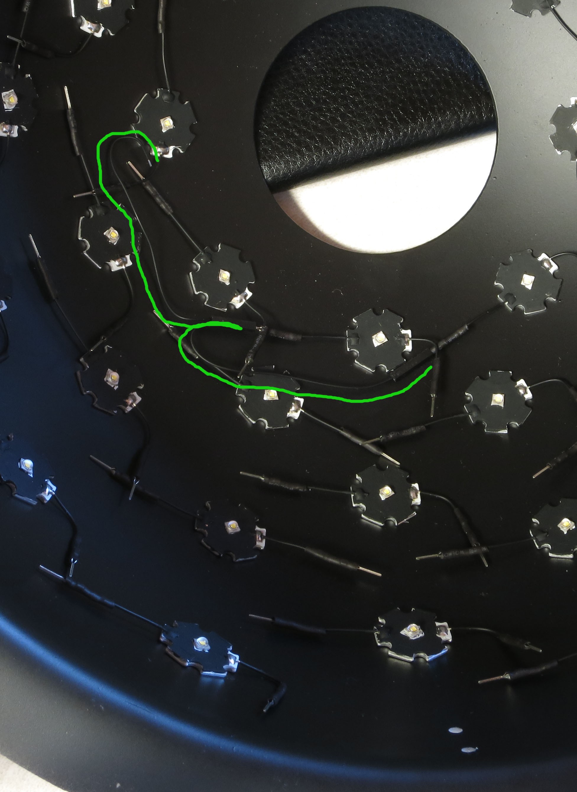
Similarly, you’ll be connecting all the + LED leads together in a column. Unlike the row, though, the column elements are a bit staggered, so you’ll need to zigzag back and forth:
![]()
The last lead will be a short one at the bottom, which you’ll be connecting to another wire.
Quick note: some of the upcoming pictures will show the + leads bent down towards the bottom, like this:
![]()
DON’T DO THIS!!! I had an idea that this would make the wiring a bit easier. I was wrong, and ultimately wound up bending them back. Just leave the + LED leads as straight as they were when you glued the LEDs inside the dome – it makes the wiring a lot easier.
Let’s start with the rows. You’re going to have to connect 8 pieces of wire together, 7 bridging the 8 LEDs in the row, and the last one leading down to a hole you drilled near the base in the previous step (it’s the hole at right in the picture above). What length should the wire be? The wire length will depend on the size of the dome, and the number of columns in the row. You’ll have to choose a wire length long enough to connect adjacent ground leads, plus some slack to let you bend the wire into a position that doesn’t block light from the LEDs. However, a good first guess for the wire length can be obtained by measuring the distance between two adjacent LEDs in the row, then adding about 1.5” to that.
Start by cutting two pieces of wire that length, and stripping off 2.5-3mm of insulation off each end. Crimp a female Dupont pin onto the end of one wire, the same way you did in previous steps. Now comes a slightly trick step. You need to hold the uncrimped ends of two wires together, and then crimp both of them in a single female Dupont pin. The tricky part is that the crimp end of the Dupont pin is just barely big enough to fit two wires, but you have to stick them in just the right way. The best way I found is to pinch the two wire ends together as close as possible, and then slide them into the crimper vertically (perpendicular to the general orientation of the crimper). Most times, you will feel them slide in a bit, and then stop as the insulation catches on the end of the pin. Don’t crimp at this point; while it might work, I’ve found that more often than not the crimping doesn’t hold, and one or both wires fall out. You need to get a little bit of the insulated part of both wires into the crimp end of the pin. To do this, you need to gently jiggle and twist the two wires in the crimper, until you feel them start to slide a bit further in. This is your signal that you’ve got the insulation in the crimp end, and you can finish the crimping process. These first two wires crimped together should look like this:
![]()
As in previous crimpings, put a bit of solder on the crimped end to secure the wires and ensure good electrical contact. Then take two of the 1-pin plastic female Dupont housings, and slide the pins into them. They may slide in easily to the end, but more often than not they will likely slide in partway and then stop. They need to slide in all the way to the end, otherwise the LED male Dupont pin will not be able to make contact with the female Dupont connector above. The best method I’ve found for dealing with recalcitrant connectors is to hold the wires at the base of the connector firmly, grip the plastic housing with a pair of needlenose pliers, then push the housing down towards the base of the connector; usually works pretty well. The pair of wires will now look like this:
![]()
Now you’ll need to check whether your initial guess for the wire length (distance between LEDs + 1.5”) was correct. Go back to the dome, and see whether the two connectors are able to reach the first two LED pins, plus a bit of slack in the wire to let you bend it into position. In the picture below, I’ve underlined the wires in green, showing that they do reach between LED leads when bent properly, with a bit of slack:
![]()
It may look from the picture as though I inserted the LED pin into the female connector. That’s because I did - but you shouldn’t. The pins are easy to bend, and if they bend and break you’ll need to pry off the LED to fix it, which is not fun. Best to only insert the pins once, and there’s some prep work that will make the pins slide in more easily (more on that in a bit). For now, just check for the proper wire length. If it looks fine, then you can stick with that LED distance + 1.5” guesstimate for all of the remaining rows. If it seems like a close fit, feel free to add a bit more length to the wire – better too long than too short.
You’ve cut and crimped two wires for the top row; now cut 5 more wires of the same length to connect the ground pins on the remaining LEDs in that row, plus one more last wire long enough to reach from the last LED in the row down to the hole at the base of the dome. Keep crimping two wires together until you get to the last longer wire, and crimp a female connector to the single end of that last wire. Stick the female pins into the plastic housings, bend the wires so that they’ll connect more easily to the LEDs, and you should have something that looks like this:
![]()
The first LED connector is at lower right, and the longer wire that should reach to the base of the dome is near the top. Stick a male Dupont pin into each end, then use a multimeter to make sure you have good electrical connectivity between both ends. For extra safety, you can check to make sure that every intermediate connector has electrical connectivity, but I’ve found that if the ends are electrically connected, the rest of the connectors are usually good as well.
One more thing. Take a male Dupont pin, and slide it in and out of each of the female connectors 2-3 times. I’ve found that this helps make the LED pin slide in more easily, making it less likely that it will bend.
Time to wire up the top row. Start with the LED on the end of the row, and slide the connector onto the LED ground pin. The safest way to do this is to hold the ground pin firmly flush against the side of the dome so that it can’t move, then hold the female connector/housing against the dome surface and slide it onto the pin by pushing against the back end until you feel it go in as far as it can. Be careful not to force it, as this might bend the LED pin. If you're not sure about this, practice with some scrap connections outside the dome until you get a feel for it. Repeat this with every other LED ground pin in the top row. When you’re done, it should look like this (wires and connectors are paralleled by the green line):
![]()
The last wire on the right is the lead that goes down to the base of the dome (out of the picture), and will ultimately be connected to one of the two power cables.
Don’t worry too much at this stage if wires are blocking LEDs – wait until all the wiring is done before bending wires out of the way.
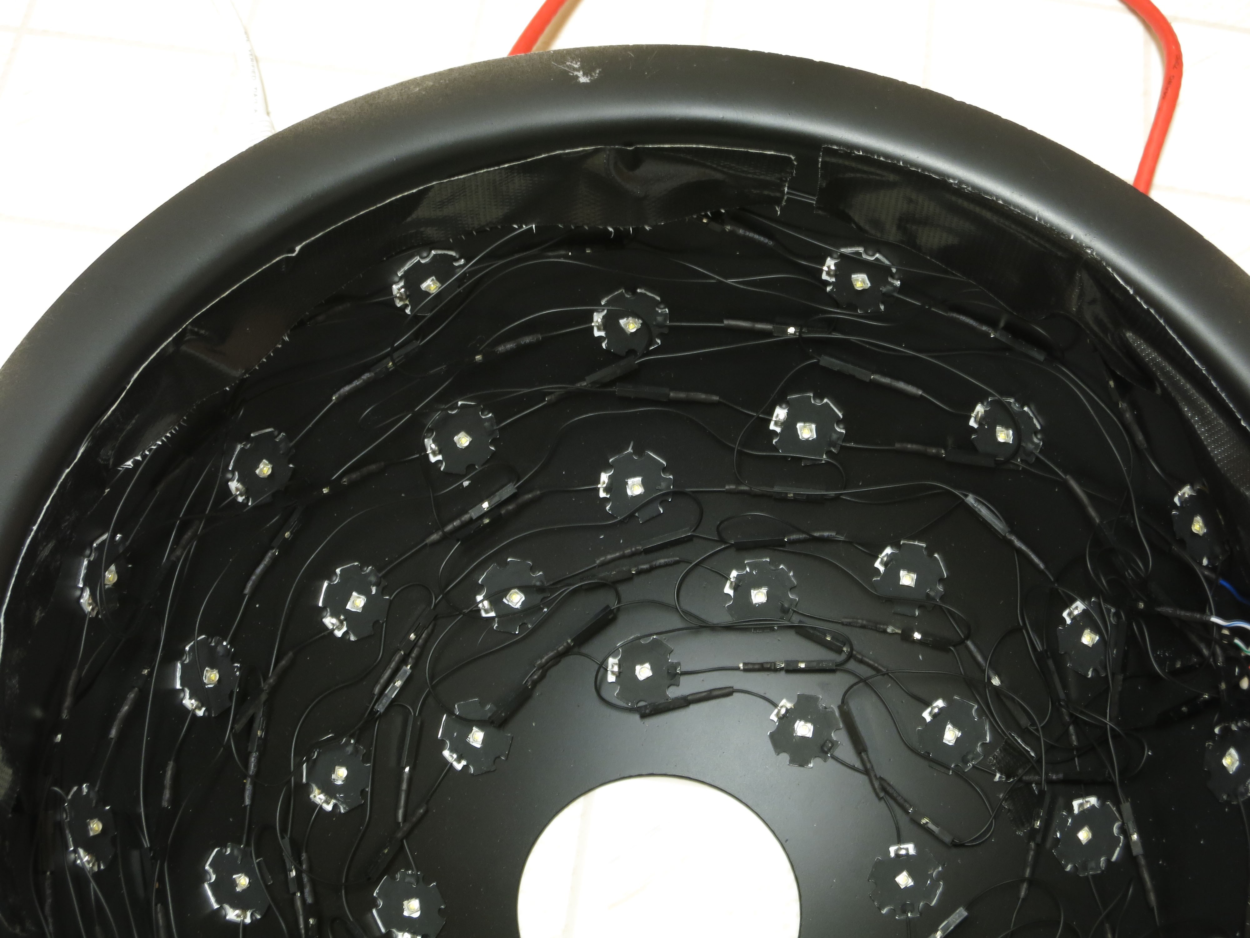
Repeat this process for all the rows in your dome, 6 in this case (8 max):
![]()
Now repeat the process for the columns, using the wiring pattern in the picture below as an model example for every LED column in the matrix:
![]()
The bad news is that every wire between adjacent LEDs in the column will probably have to be a different length, since the distances are shorter near the top and longer near the bottom. The LED distance + 1.5” rule is again a good starting guess, possibly even a bit longer than it needs to be. The good news is that if you keep track of the correct lengths for the first column, you can just repeat the pattern for every column, since those distances should be the same for every column. The last lead in the connector wire, the one closest to the bottom of the dome, should be about 1.5” in length.
Now that all the wires are done, bend down any wire slack flush with the interior surface of the dome (doesn't have to be touching), while not blocking any of the LEDs. The picture above shows a reasonably acceptable example of this for the rows. When you do the bending , be careful not to bend any of the wires where they’re soldered to the LED; bend it too far at this location, or too many times, and it may break. For all except the bottom row, try to bend the wires below the LED row, closer to the bottom of the dome; for the bottom row, bend them to be above that row. Doesn’t have to be pretty, since the dome interior will be unseen most of the time. It’s also OK to have the wire touch or go across an LED star, as long as it doesn’t block the actual LED in the middle.
-
24Step 24
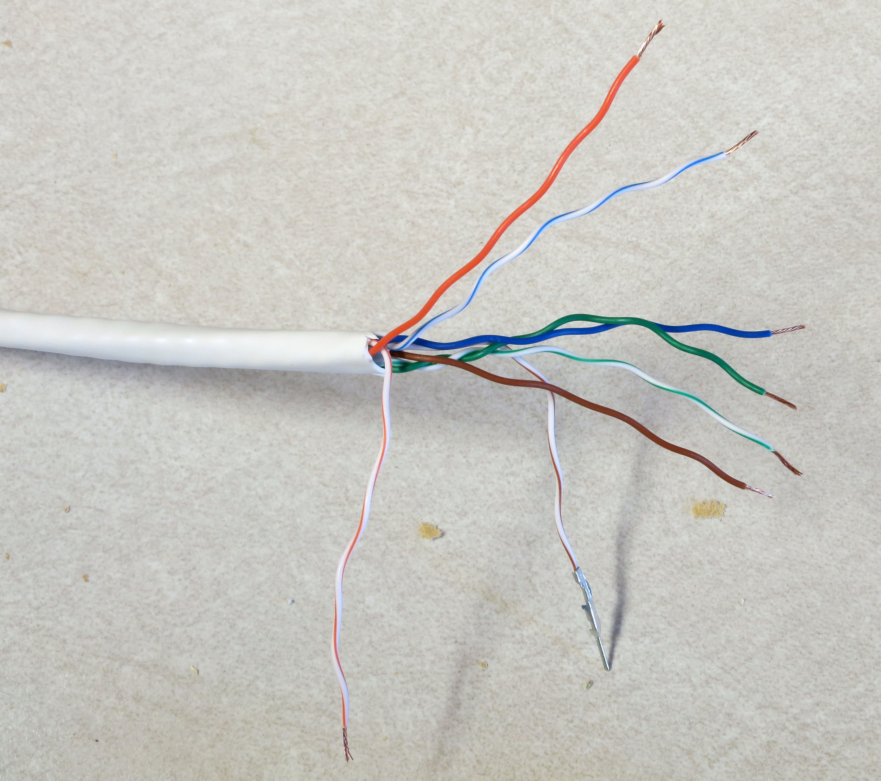
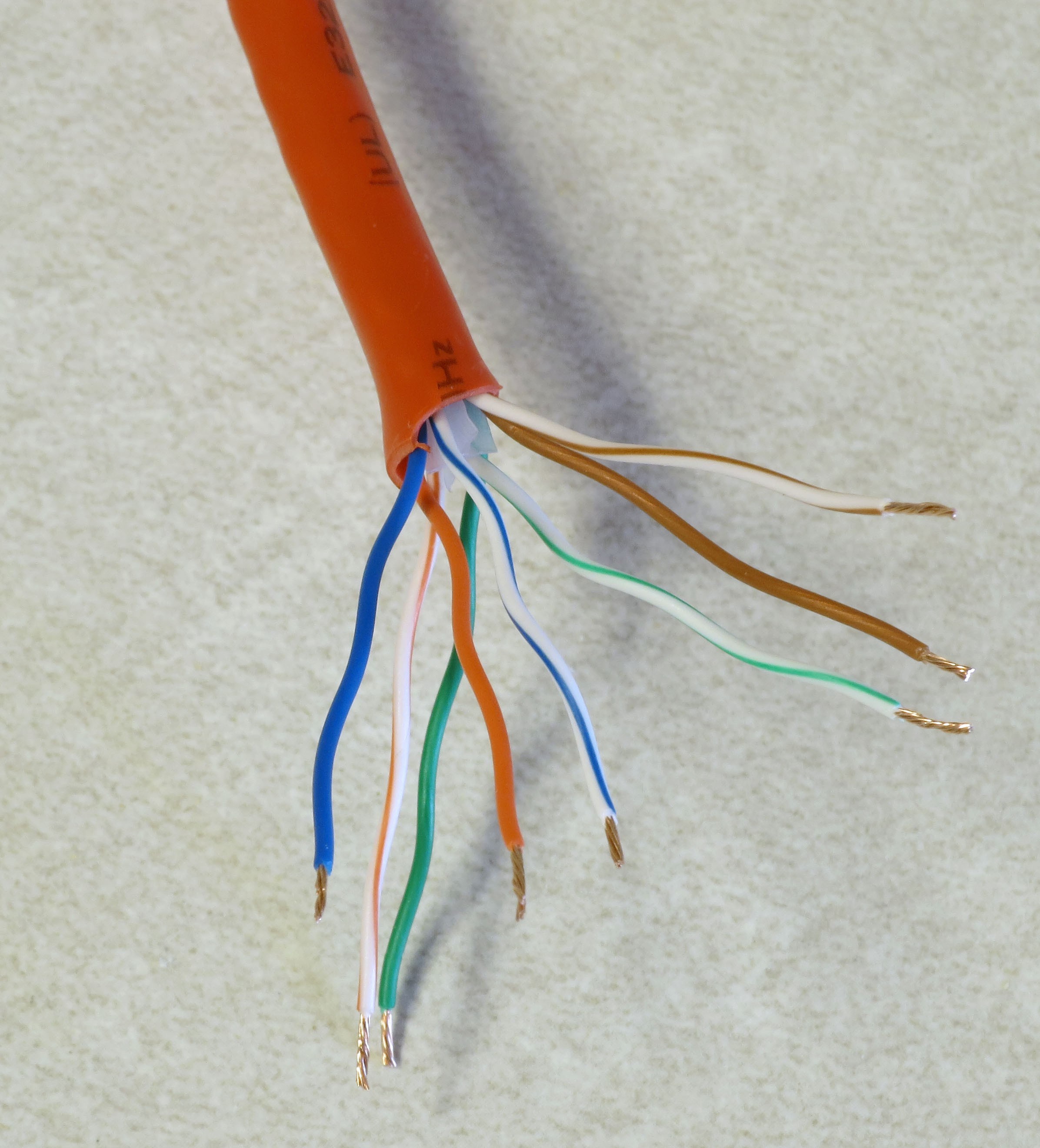
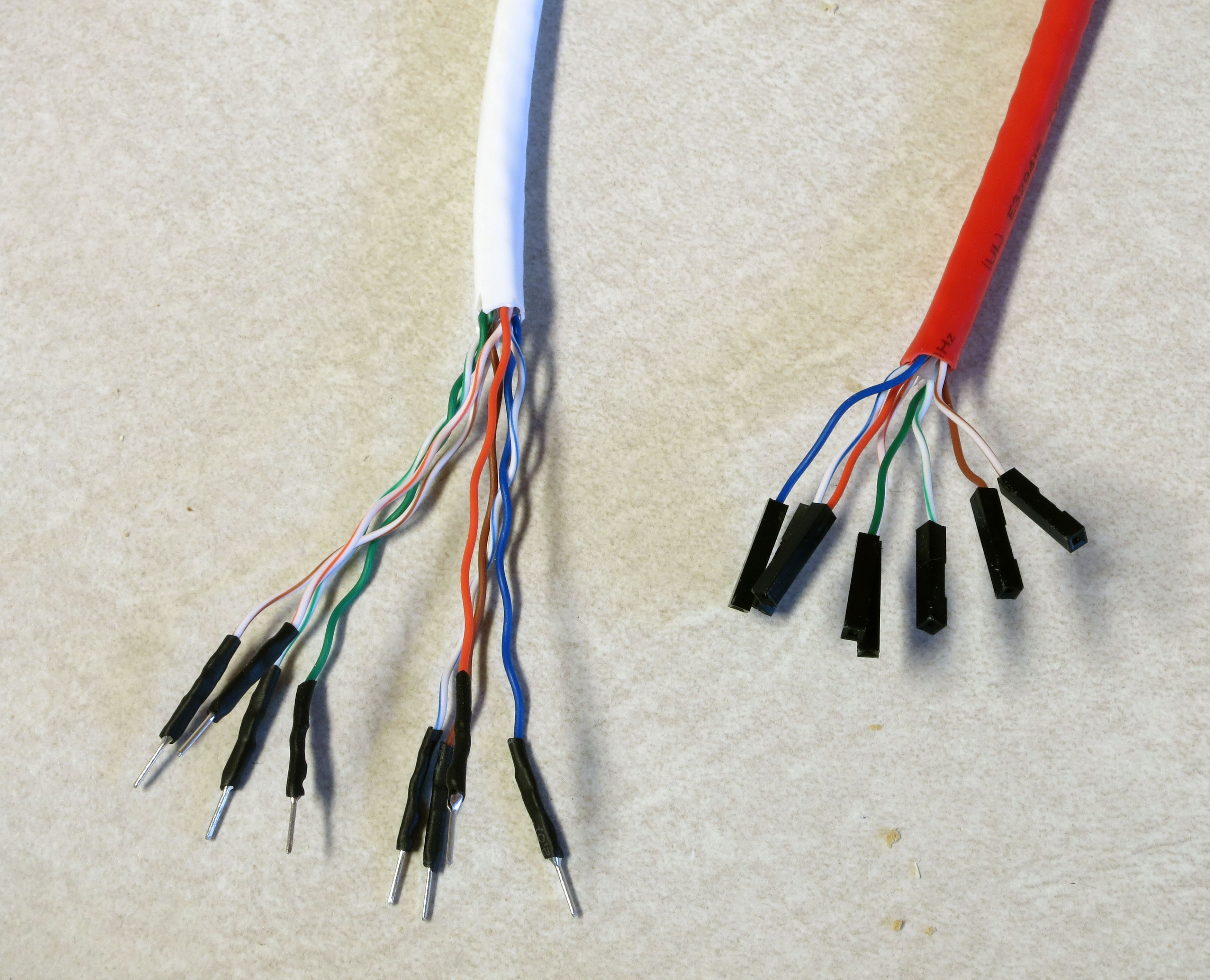
ow that the LED matrix is fully wired, the last step is to make the connection between the matrix rows/columns and the power cables. Power is supplied using Ethernet cables, the same ones you chopped one short end off of in a previous step to make a testing cable. Grab the remaining cables, and trim them both to be the same length. The recommended original length was 7 ft., and 5-6 ft. is a reasonable trimmed length (longer for big domes, shorter for smaller ones). If you start with a 5 ft. cable, 4-4.5 ft. is OK.
You should have one red cable, which will supply positive voltage to the columns, and one cable of some other color, which will connect the rows to ground. In this case, I have a white cable that will do the ground connections (to color-coordinate with the white dome). Using the same method as in a previous step, cut off about 2” of exterior insulation from both cables, trim off any central plastic rib, unwind the paired wires, and trim off about 3 mm of insulation from the end of each wire.
![]()
![]()
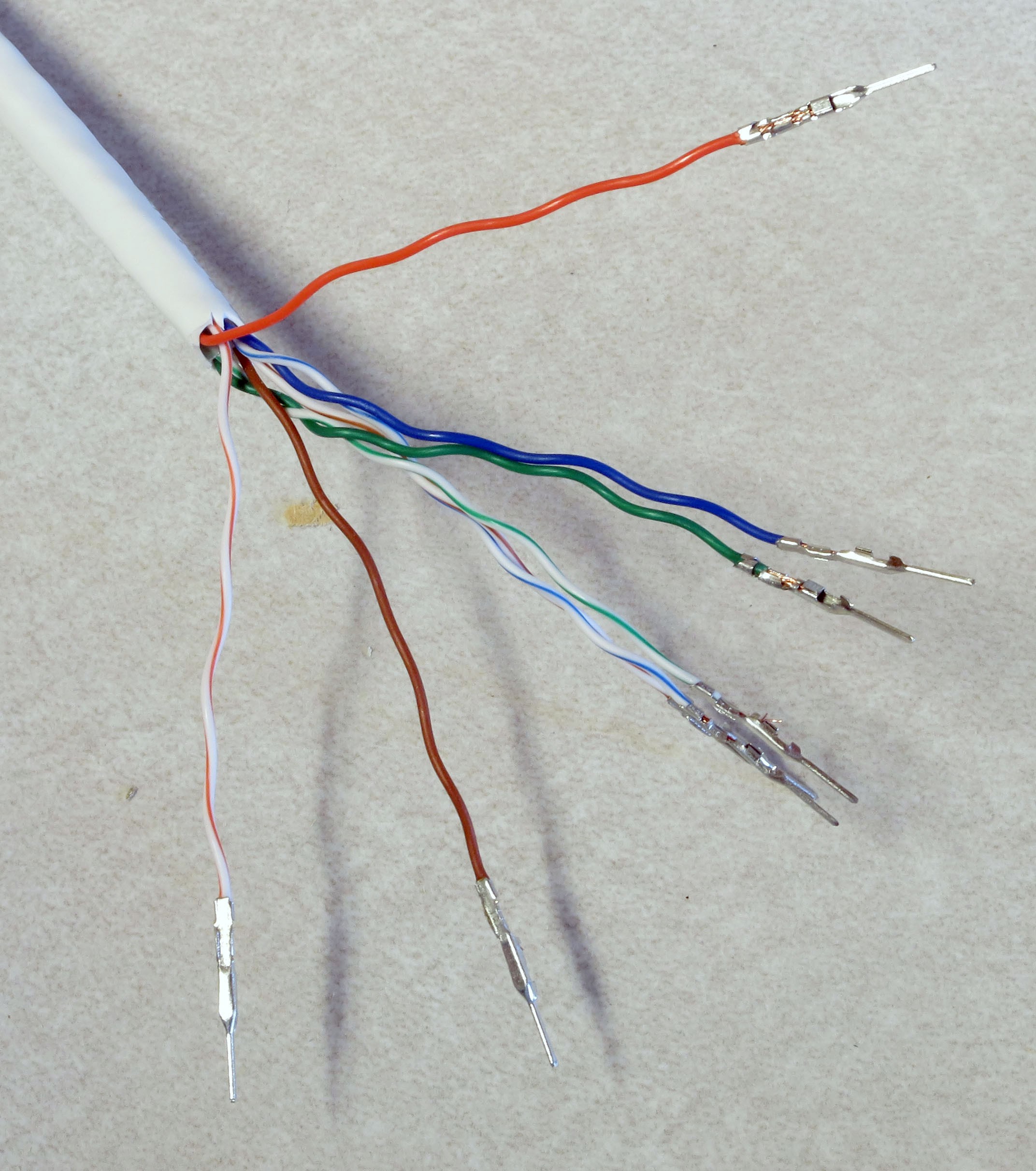
Crimp male Dupont pins onto the ground (rows) cable wires:
![]()
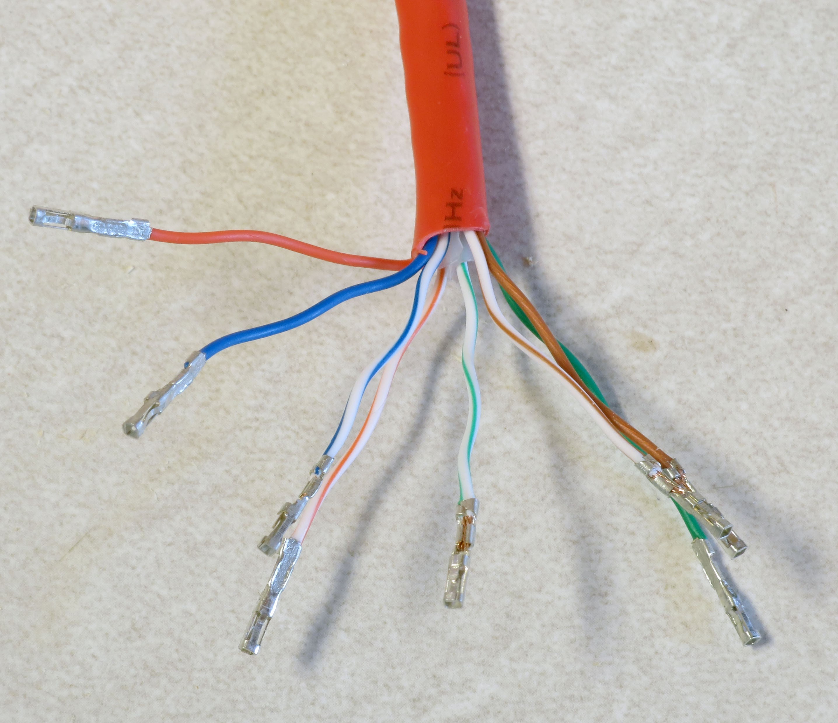
Crimp female Dupont pins onto the MOSFET (columns) cable wires:
![]()
As with earlier similar steps, put a bit of solder on the crimped end to hold the wire firmly in place and ensure good electrical connectivity. Then put some heat shrink tubing on the male Dupont pin connectors to insulate them, and slide the female Dupont connectors into plastic housings to insulate them. With the latter, you may have to use a pair of needlenose pliers to get them to slide all the way into the housings. You should wind up with the ends of the Ethernet cables looking like this:
![]()
You’ll notice that the wires on the red cable are shorter than those on the white cable, even though I specified that you strip off about the same length of external insulation. That’s because I decided later on that the original length of 1” on the red cable was too short, and stripped off more insulation to make them 2” long.
I've also made a very subtle mistake here. Each of the wires coming off the white cable attaches to one of the rows in the dome. But there are 8 wires here, while there are only 6 rows in the dome – two of the wires are unneeded. Looking at the Ethernet cable wire chart:
![]()
For the dome I’m building here, I want to get rid of the cables for pins 7 and 8 on the white cable, since there are no rows 7 and 8. Those correspond to the wires with white/brown and brown colors, so I cut those off. Obviously, if you build a dome with the maximum allowed 8 rows, you would leave those wires in place. There are 8 columns of LEDs in the matrix, so I leave the wires on the red cable untouched; if there were fewer than 8, I would have trimmed off some of the higher-number pins as well.
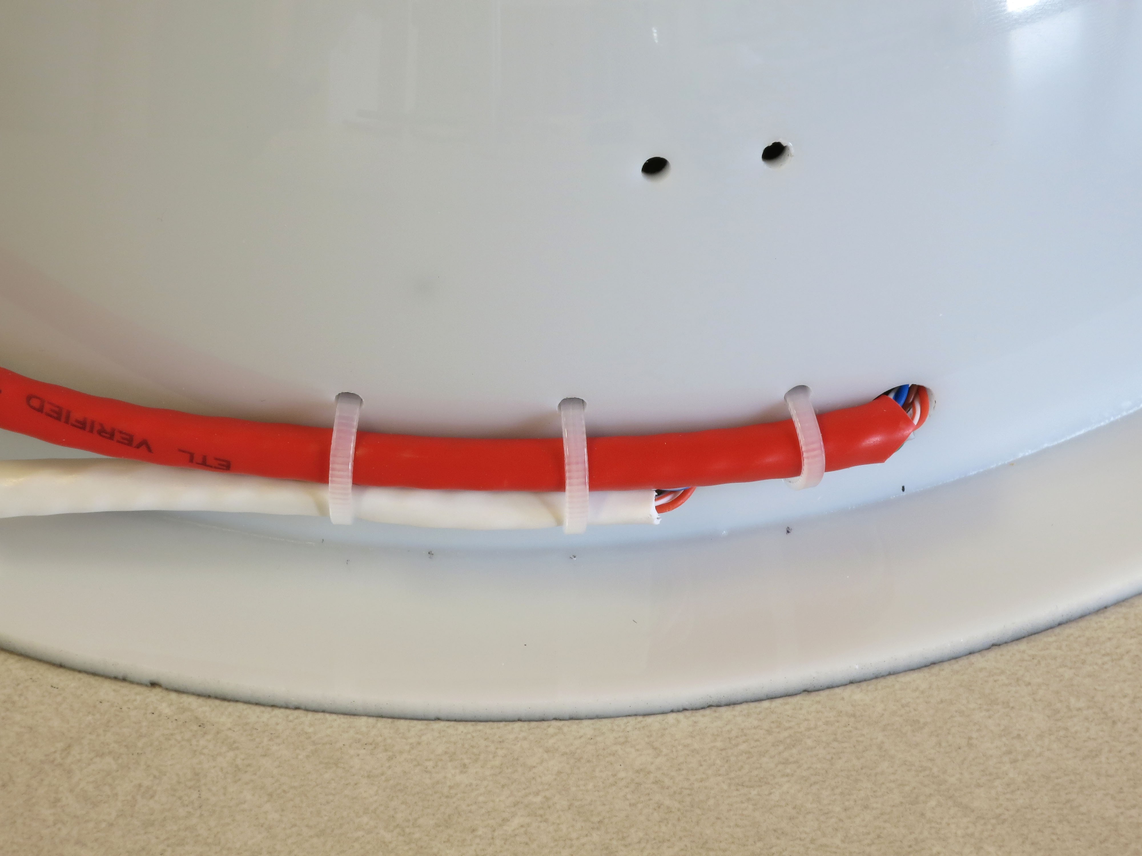
Next, install zip ties in the hole pairs around the rim; the ratchet part of the zip tie should be on the inside. If you’re using additional zip ties up the side, install them there as well; as I mentioned in a previous step, I drilled the holes for this dome but decided that the zip ties weren’t necessary for such a small dome. Don’t tighten them up yet, leave them mostly "unzipped" for now.
![]()
Feed the Ethernet cables as shown in the photo below through the zip ties near the large holes, feeding the wires from the cables through the holes into the inside of the dome.Make sure the red cable feeds into the indicated hole, with the ground cable (white in this case) going into the other hole. When the cables/wires are in place, tighten the zip ties as tight as possible – use pliers if necessary to make the ties tight enough to hold the cables firmly in place. Trim off the excess for these specific zip ties on the inside after you’re done, to get them out of the way.
![]()
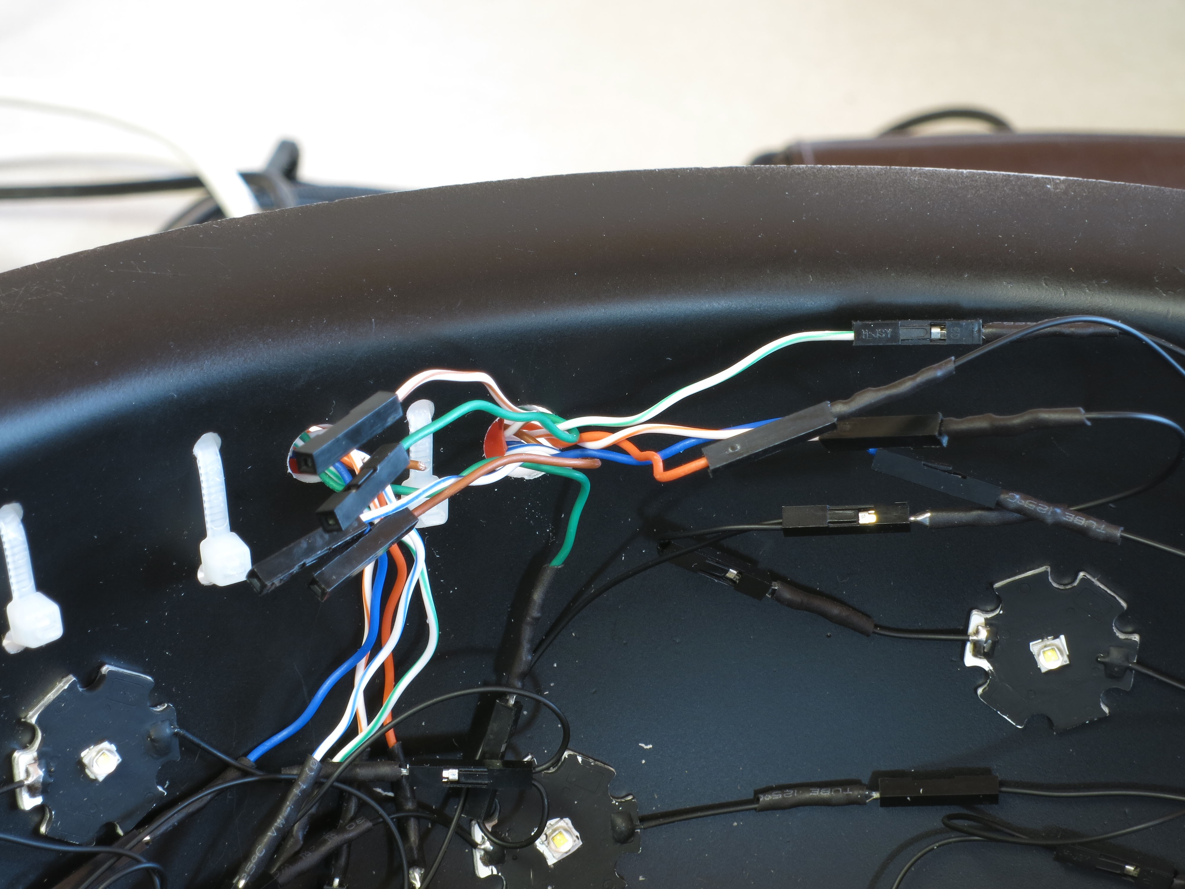
Here's how those cable wires look on the inside, before they’re connected to anything:
![]()
The wires from the ground cable (the white one) have male pins, which will be plugged into the female pins coming off the ends of the rows. You’ll want to follow the Ethernet cable chart above to figure out which color wire plugs into which row. For example, wire 1 is white/orange, so you’ll plug that pin into the female connector for row 1, wire 2 (orange) to row 3, etc. until all the rows are connected. Try running these connection wires underneath other wires in the dome as best as you can. Final result should look something like this:
![]()
Next come the connections to the positive voltage cable (should be the red one, always). There are female connectors on this cable, and female connectors at the base of the wiring of every column. So you’ll need to measure and cut 24 AWG Kynar wire lengths that will be long enough to run from the base column connector to the corresponding wire from the red cable. When measuring the wires, measure along the surface of the dome, just above the base. Crimp male Dupont pins on both ends, solder and heat shrink tube the connectors on these wires, and then connect them to the corresponding female connectors; run them through the zip tie wire guides along the base of the dome. First, do the first four connections running in order, white/orange to the nearest LED column on the right, orange to the second, white green to the third, blue to the fourth:
![]()
For the other four, work in reverse order in the other direction. In other words, brown (pin 8) will connect to the closest LED column on the other side, then white/brown (pin 7) to the next closest, and so on; as before, run the wires through the zip tie guides. You could run the wire for pin 8 all the way around the edge of the dome, but doing it this way reduces the amount of wire you need. When done, the full set of positive voltage connections to LED columns should look like this:
![]()
Time to test the wiring. I’ve written two programs that will test all the LEDs; you should find these in the Files section. The first one, Dazzler, lights up the LEDs at random:
The second one, Serial_Test, lights up the LEDS one at a time, first by row, second by column:
Upload these individually to the Arduino controller using the Arduino IDE (described in an earlier step). The default setting for both these programs is 8 Rows, 8 Columns; if your dome has fewer Rows or Columns, modify the appropriate constants in the program. So for my test, I changed the Rows constant from 8 to 6 (no decimal point). If you’ve finished the control box while waiting for the LED adhesive to dry, use that; otherwise, use the same wiring configuration in the system test done earlier. Plug the dome’s red cable into the MOSFET board Ethernet connection, plug the ground cable into the CAT4101 board Ethernet connection, then plug the 9V power supply in – if you only have the USB cable plugged in, the lights will not go on. Dazzler looks cooler, and spots major problems faster. Serial_Test runs slower (set the time in milliseconds with the LED_Time constant; default is 200 milliseconds = 0.2 seconds), which lets you pin down a specific LED that might be a problem.
Hopefully, all the LEDs will light up, and everything will work fine. But if it doesn’t, don’t worry – didn’t work for me the first time, either. If a row doesn’t light up, double check the matching wire connection on the ground cable; for a dark column, check the connection on the red cable. For an isolated LED, carefully check the connections to both pins of the LED. In my case, one of the columns didn’t light up the first time I tried it; after unplugging and re-plugging in the appropriate column wires, it worked perfectly.
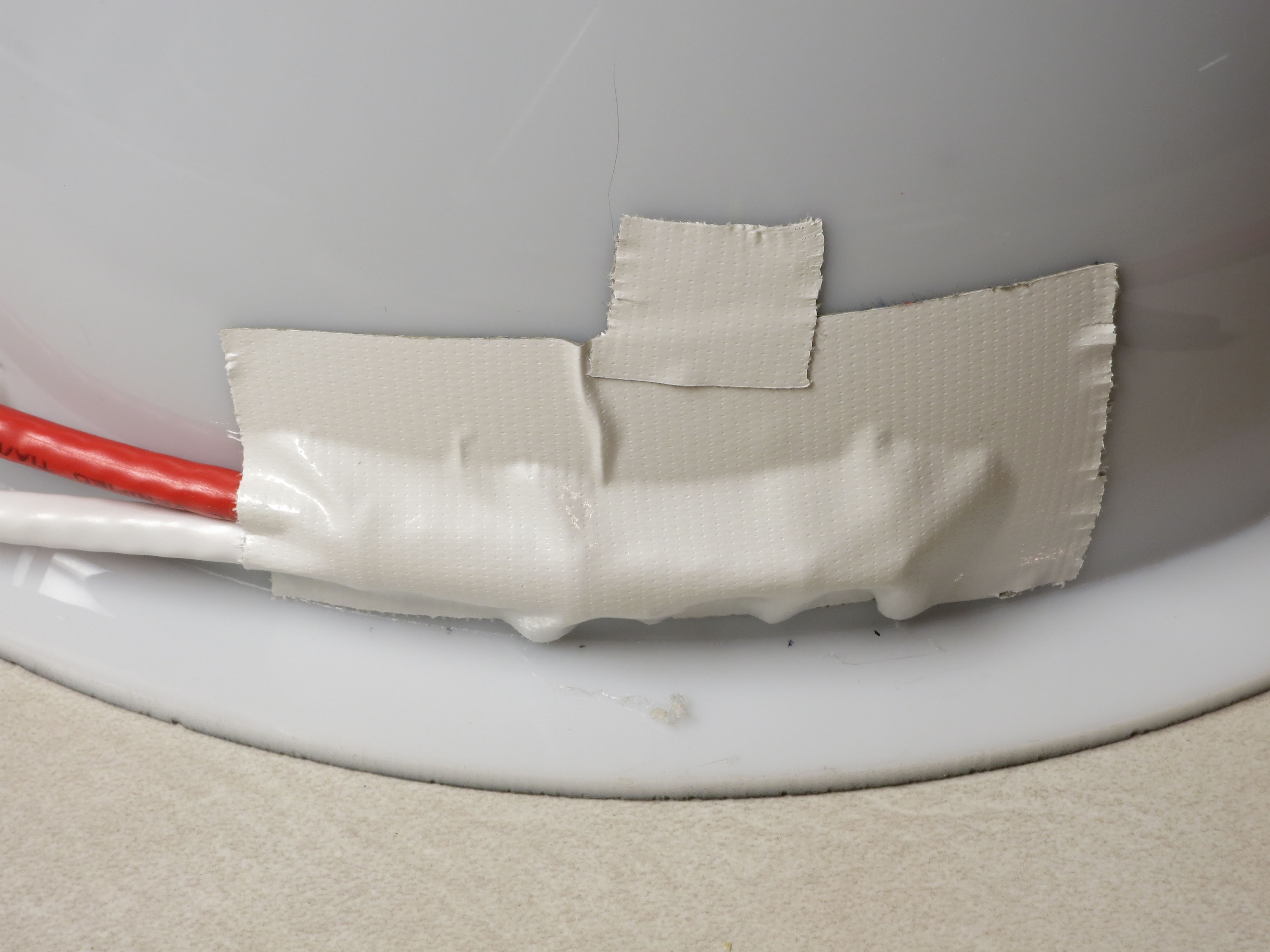
When all the LEDs are working, the wiring is done! Tighten up all the zip ties, and trim off the excess on the inside. If the dome will be sitting permanently in one location, you can leave the interior as is. Since this dome is designed to be portable, I cover the wires on the bottom of the interior with black Gorilla tape to keep them more secure (less prone to being accidentally yanked):
![]()
One problem with Gorilla tape is that it’s glossy, so it will reflect light from the LEDs to places you may not want it. To fix this, I painted the Gorilla tape with flat black paint to dull the finish.
I like to seal up the two holes where the wires/cables go into the dome, just to keep them from rubbing on the edges. Use silicone adhesive, or in my case, hot glue:
![]()
![]()
Finally, I put some Gorilla tape over the cable zip ties and holes, to make it look cleaner:
![]()
I also have an extra piece of tape covering up the holes I drilled but didn’t use. Feel free to omit this tape if you want, or use some oth
-
25Step 25
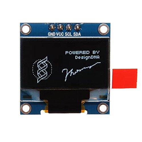
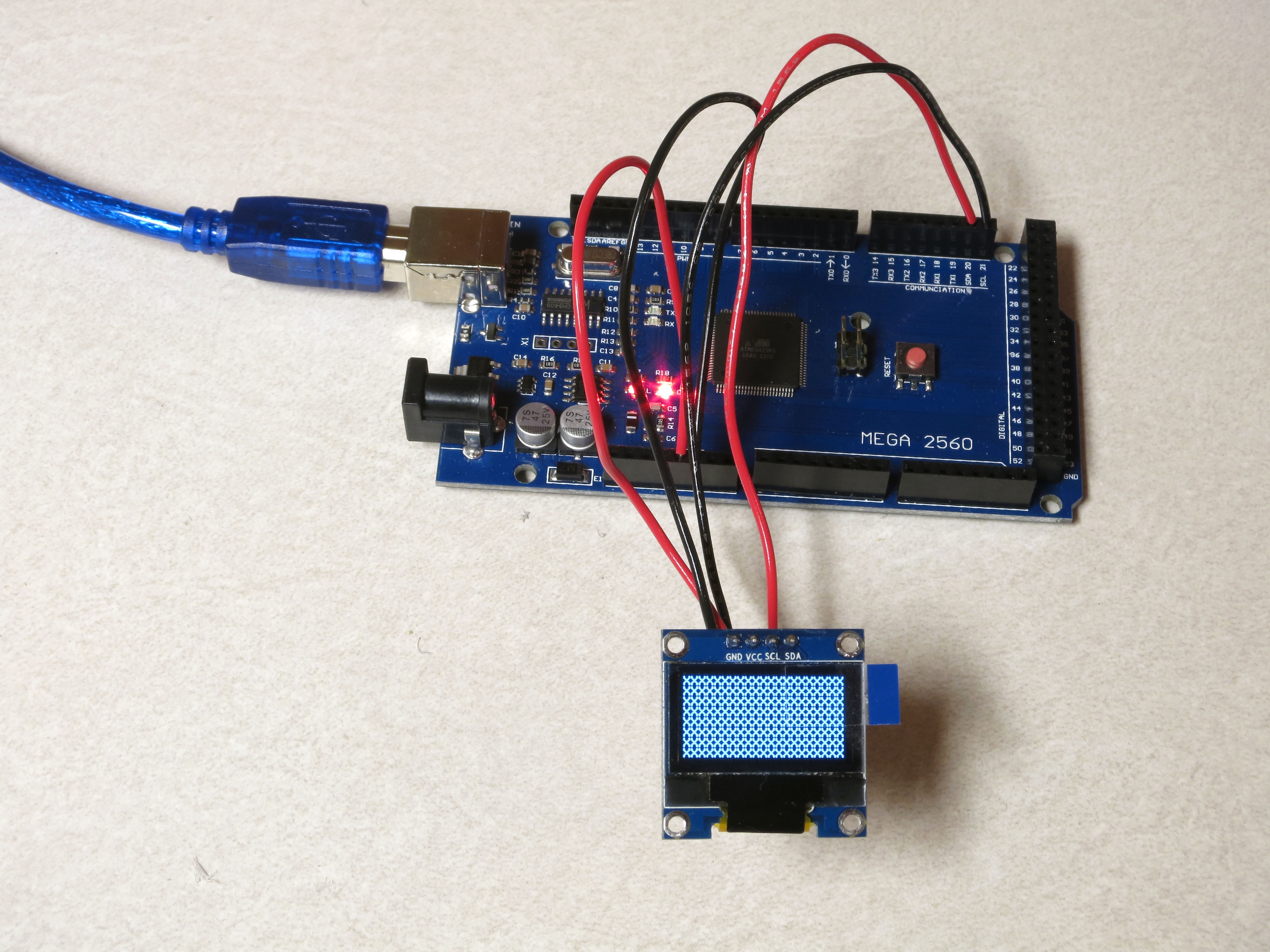
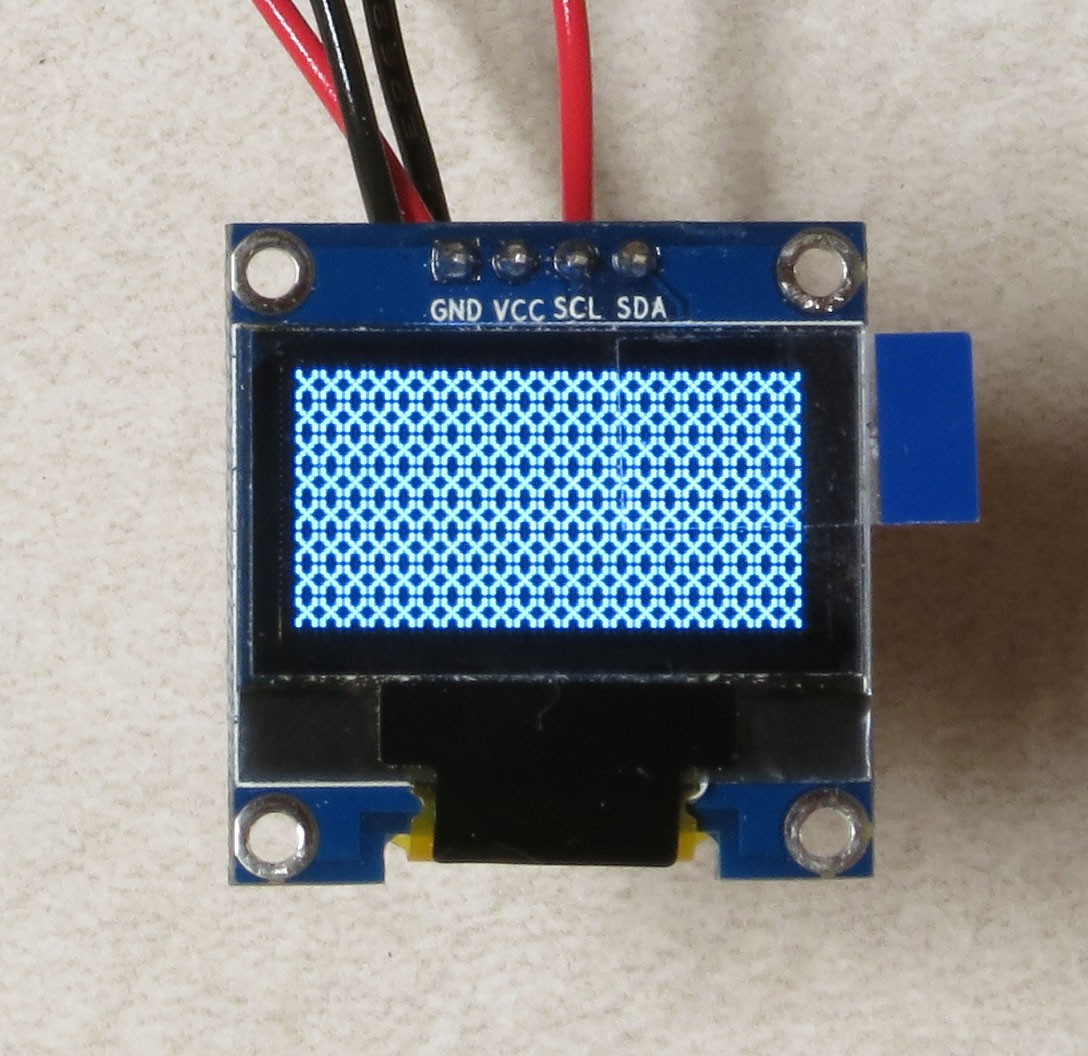
The big addition I made to the RTIMage controller in my latest generation is a small OLED display (0.96”width, 128 x 64 pixels, maximum 8 lines x 21 characters per line). While it’s entirely optional, I highly recommend including it in your build. It gives instant feedback on the system parameters, and lets you know the status of progress during an RTI photography run. But there’s a bit of prep you need to do in order to properly install and use it.
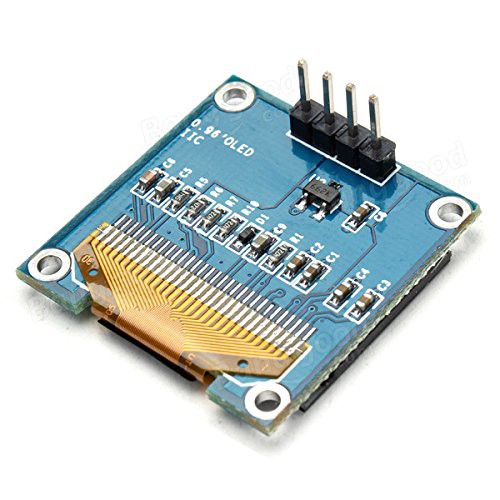
First off, while many listings for this product show that it already has pins soldered at the top:
![]()
![]()
That isn’t necessarily the case for the shipped product you might receive. If not, just break off 4 header pins from the 40-pin header strip on the parts list (should already be shrunk to a much smaller size because of previous removals), and solder it in place as seen above.
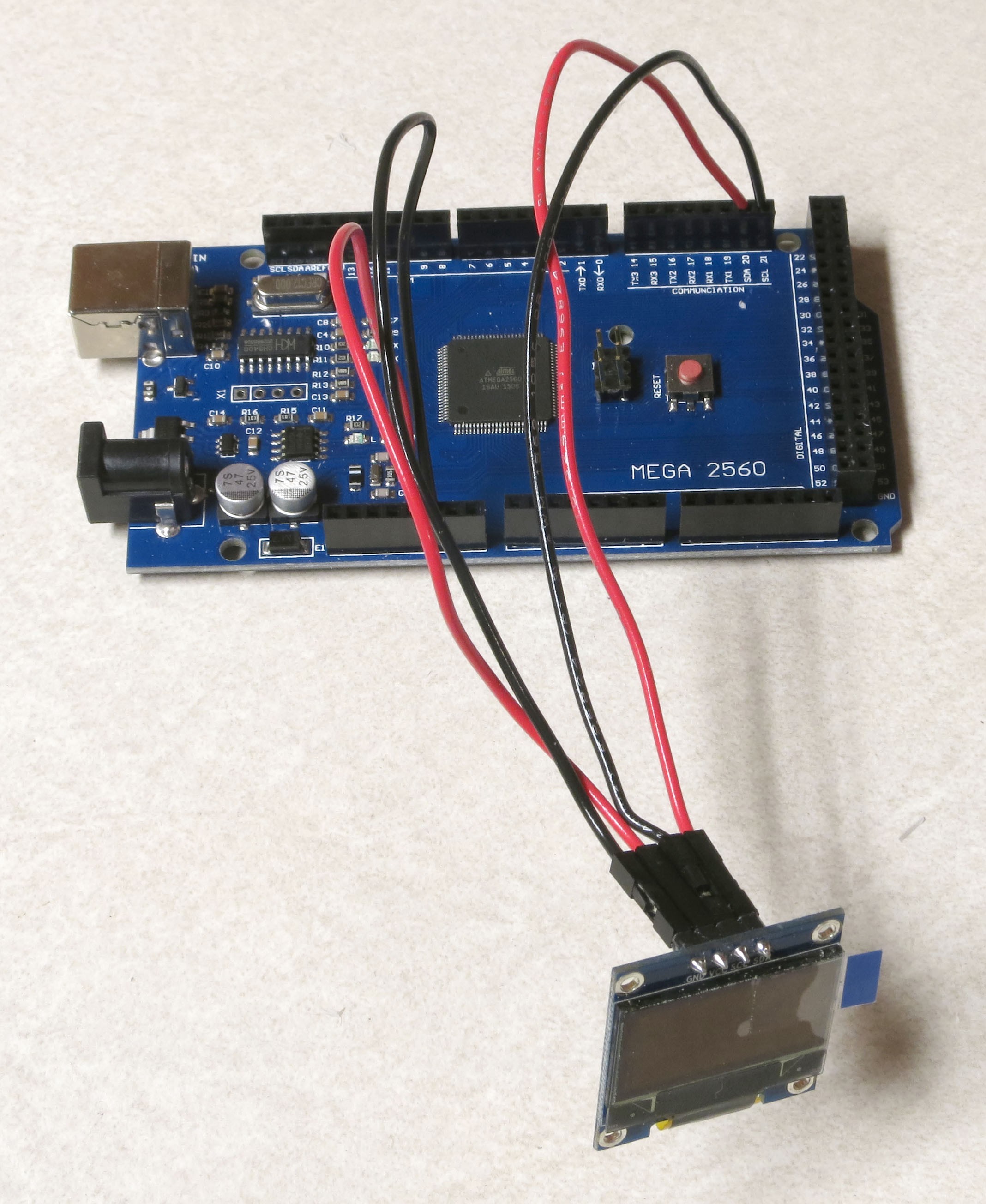
You’ll need some way to connect the pins to the Arduino. Cut 4 pieces of AWG 22 wire about 7” or so in length (two red, two black is recommended). Strip about 3 mm of insulation off one end of each wire, then crimp and solder a female Dupont pin to that end (insulation won’t fit, but the wire is so fat that you should get a good crimp regardless). Stick the female Dupont pin into a plastic housing (all the way in). Strip about 5mm off the other end. Fit the black wires onto the header for the pins marked GND (ground) and SCL; fit the red wires onto Vcc (voltage) and SDA.
Now insert the wires into the following headers on an Arduino Mega:
GND goes to any Arduino GND
Vcc goes to any Arduino 5V
SDA goes to Arduino SDA
SCL goes to Arduino SCL
![]()
This OLED display communicates with the Arduino using the I2C/IIC serial bus (Inter-Integrated Circuit). Every chip that uses this protocol is supposed to have a special address, allowing multiple chips with different addresses to use the same bus. The display I bought had an I2C address on the back of the PCB; unfortunately, that I2C address was wrong. To find the correct I2C address for any device attached to an Arduino, you can use a program called I2C scanner. It’s at this page on the Arduino site, http://playground.arduino.cc/Main/I2cScanner, but a Google search will bring up many other locations. Plug your Arduino into your PC with a USB cable, and upload the I2C scanner program using the Arduino IDE (see the earlier Arduino setup instructions for info on how to install and configure the Arduino IDE). Apparently nothing happens. Not true – the program is scanning every possible I2C address to look for devices, and if it finds one, it sends that information back through the USB cable. To see that info, go to the Tools menu in the Arduino IDE, and select Serial Monitor. A window will pop up, and eventually you will see something like this:
I2C Scanner
Scanning...
I2C device found at address 0x3C !
done
Scanning...
I2C device found at address 0x3C !
done
Scanning...
I2C device found at address 0x3C !
done
.. which will go on forever if you let it. So the I2C address of my display was 0x3C.
Next, you’ll need to test your OLED display to make sure it’s working, and to find out the limits of the area where something is visible in the display. You’ll need the latter because the display area is often not in the middle of the board, but displaced slightly up towards the top (as in the picture above). Download the zip file RTIMage_OLED_Tester from the files section, then copy the folder into your Arduino documents folder. Open it in the Arduino IDE, and look for the following line:
display.begin(SSD1306_SWITCHCAPVCC, 0x3C); // initialize with the I2C address
That 0x3C is the I2C address for my display. If your display has a different I2C address as revealed by I2C scanner, you need to replace 0x3C with that new address.
Upload the program to your Arduino. The first thing you’ll see is an Adafruit splash screen; this program is a modification of an Adafruit program distributed with the Adafruit SSD1306 library, and the licensing of this program requires that any modified version show this splash screen. After the splash screen disappears, the screen will fill up with Xes, like this:
![]()
![]()
You will need to somehow record the extents of the display area relative to the total board dimensions, and the holes. You’ll need this information when installing the display in the control box, as it will determine the position of the box cutout for the display, and the positions of the mounting holes. Once done, remove the wires (but save them for the final
-
26Step 26
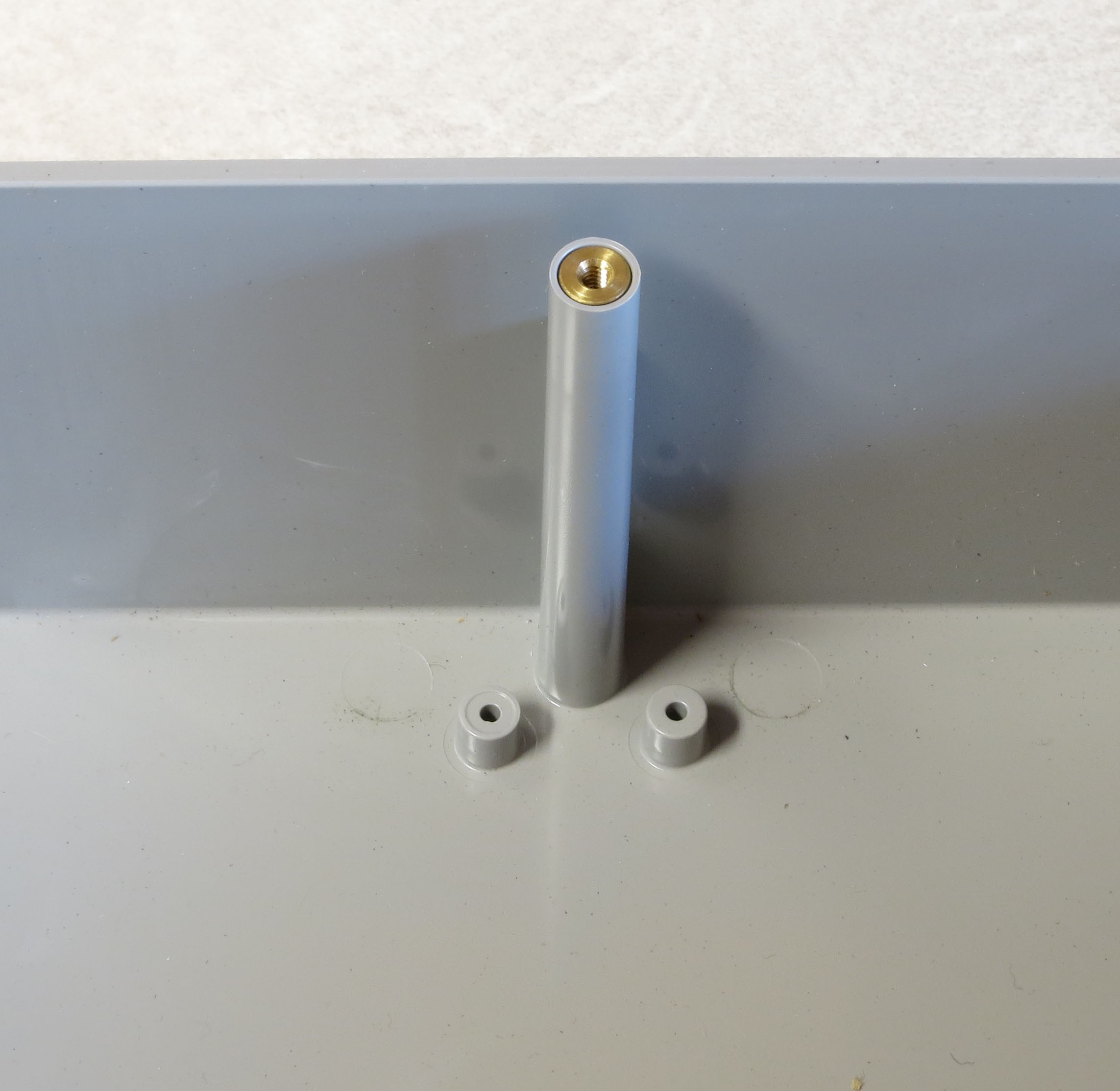
The following steps lay out the configuration and assembly of the RTIMage control/power box. The exact layout and assembly here is only valid for the enclosure box specified on the components list, the Polycase DC-96P (http://www.polycase.com/dc-96p or equivalent). If you use an alternate enclosure, you will almost certainly have to modify the layout to some degree. However, you will need to install the same components as in this build, so reading these sections is a guide for how you should plan and execute your specific assembly procedure.
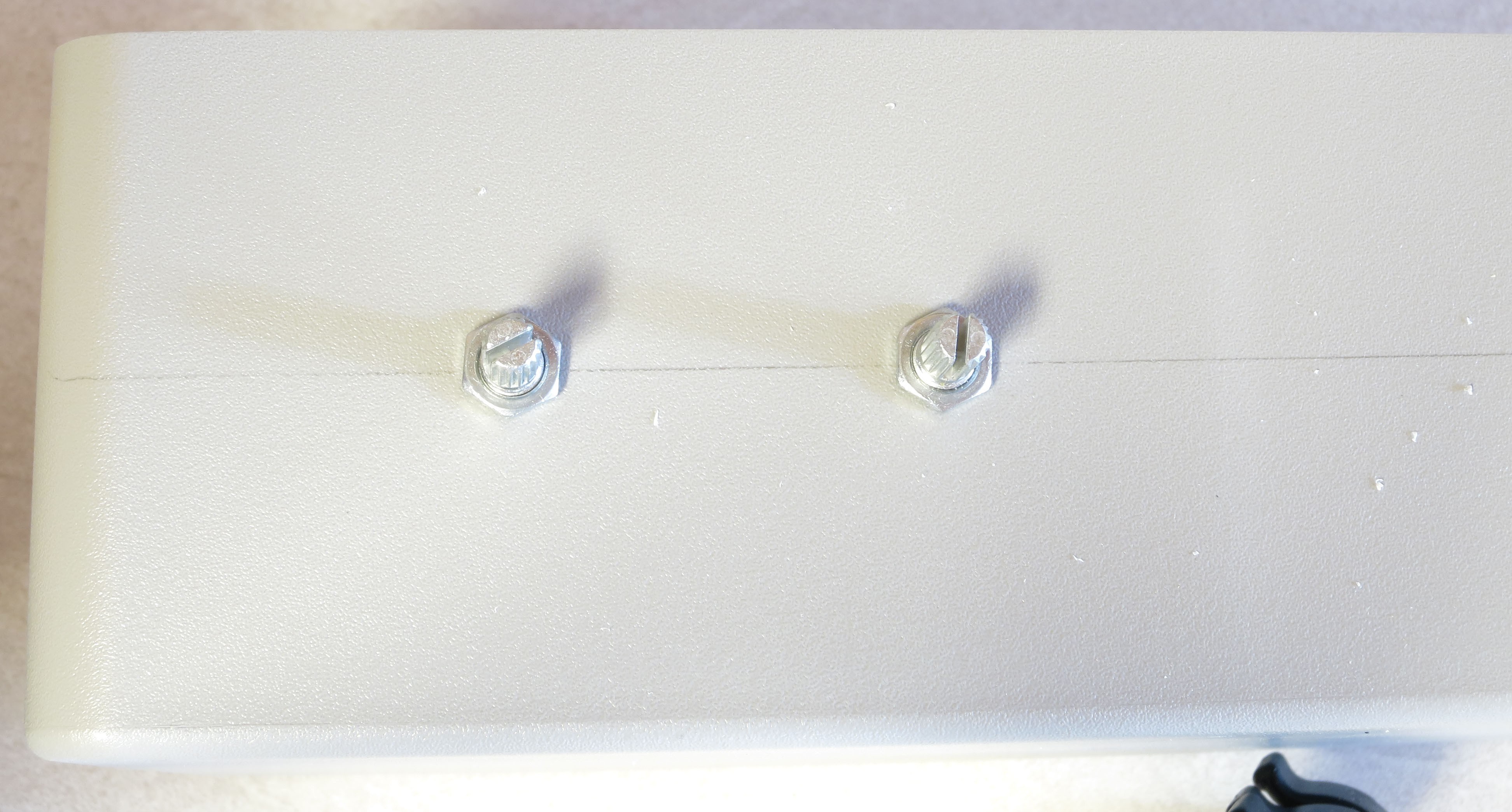
One thing you have to watch out for with the Polycase is that there are multiple internal struts that support the threaded inserts for the screws that hold the lid in place; you’ll need to avoid drilling/cutting through these, or positioning items too close to them:
![]()
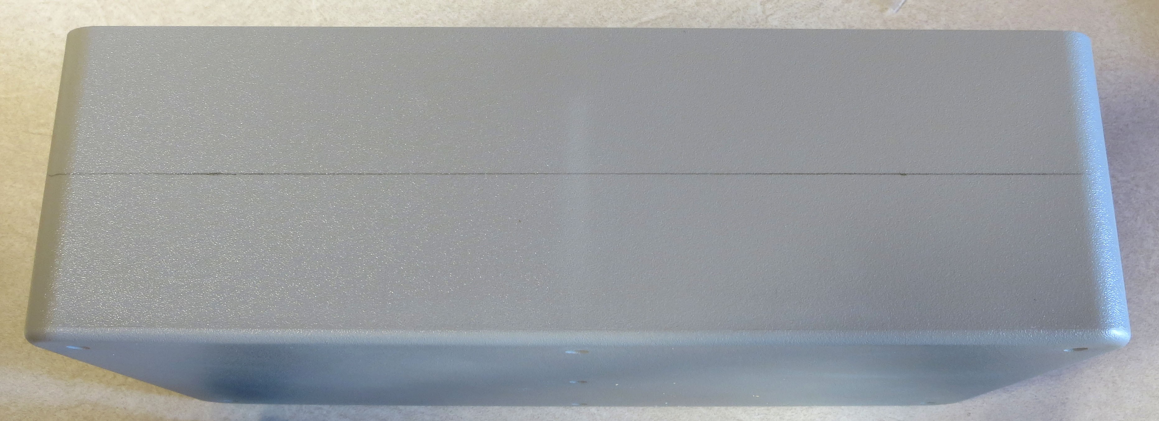
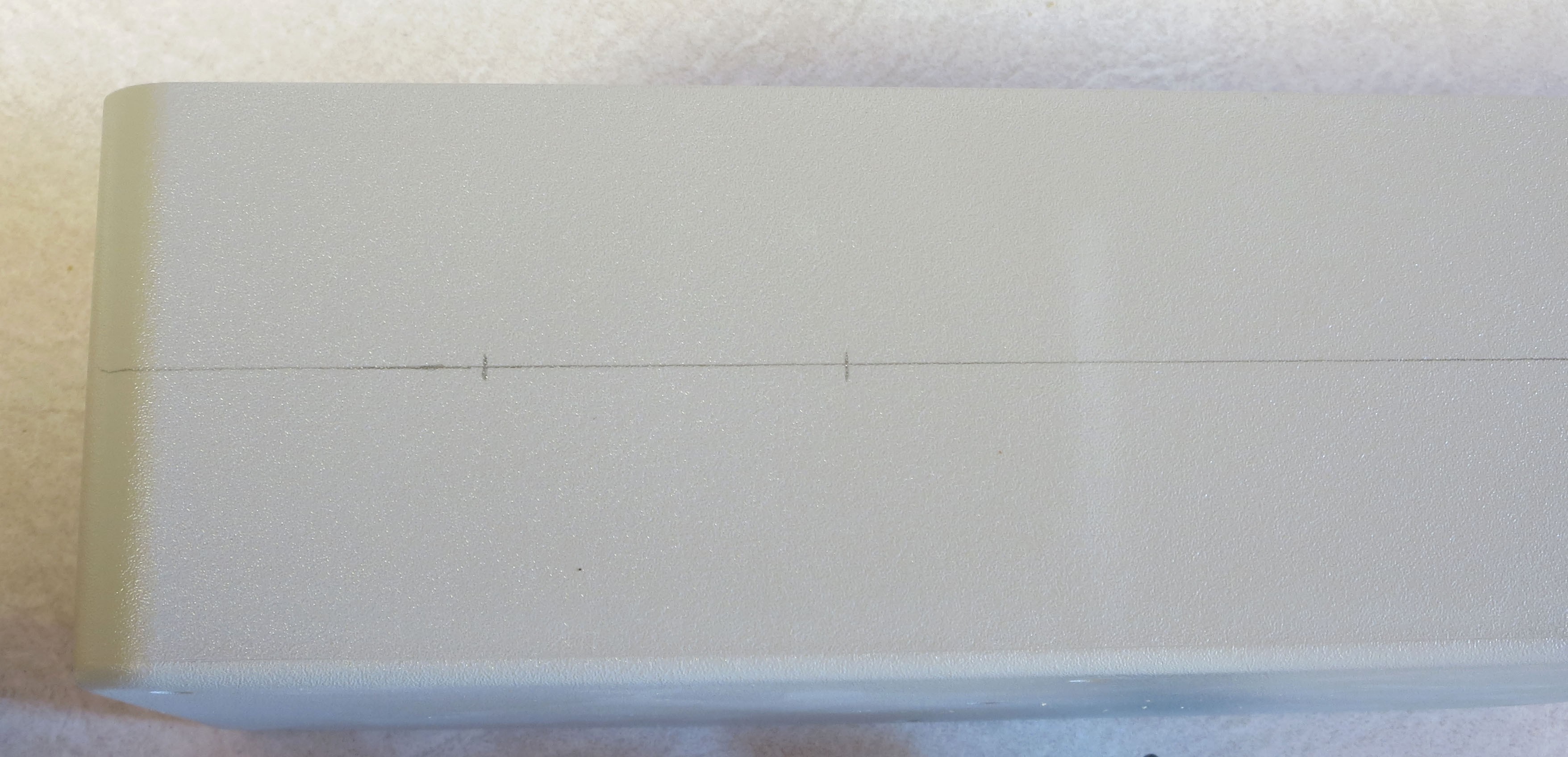
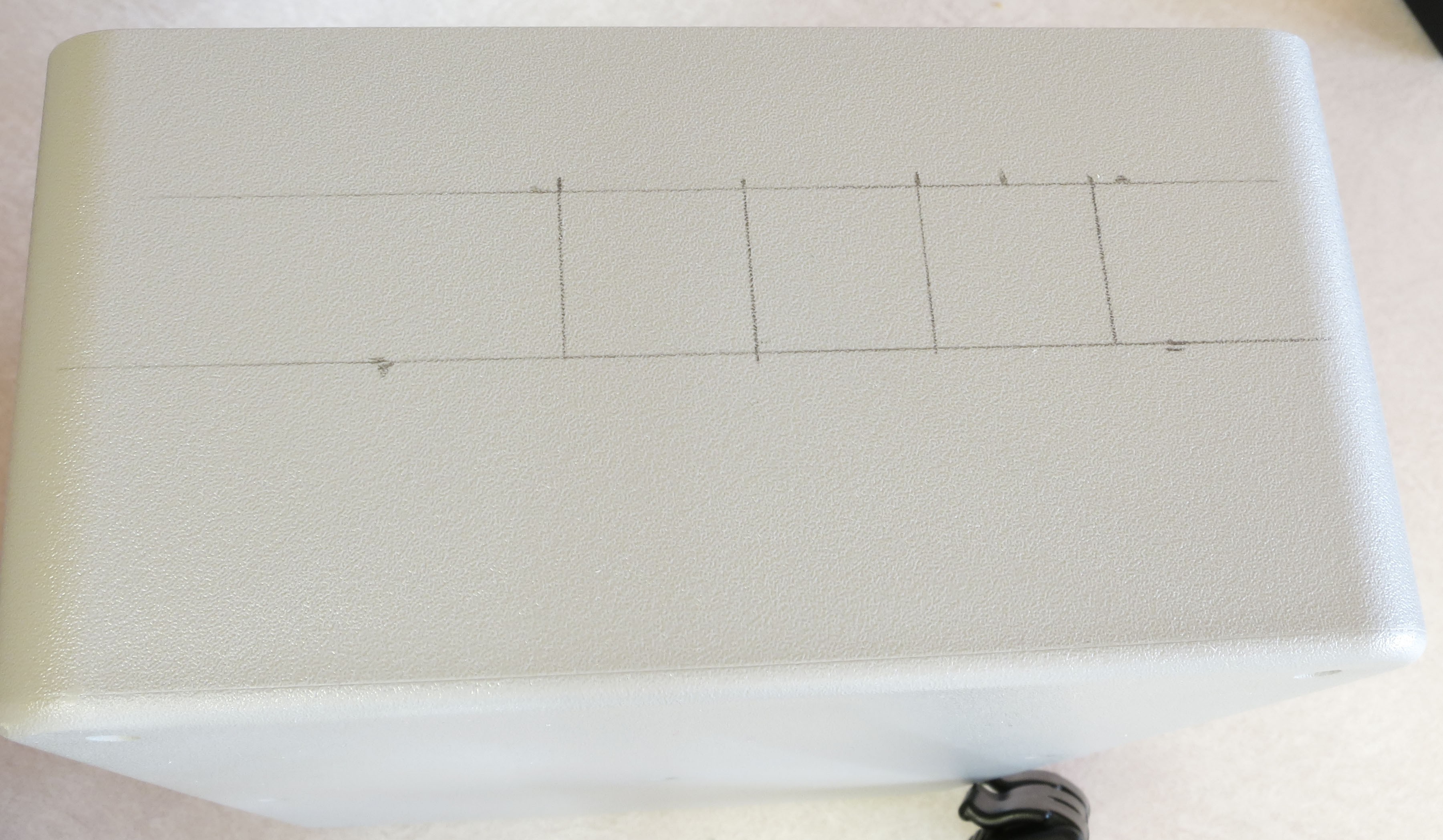
Start by picking one of the long sides of the box, and designating that as the front. To help align the holes and cutouts on the front, I draw a pencil line right through the middle of the box; make sure you have the lid on when you measure the distances for this:
![]()
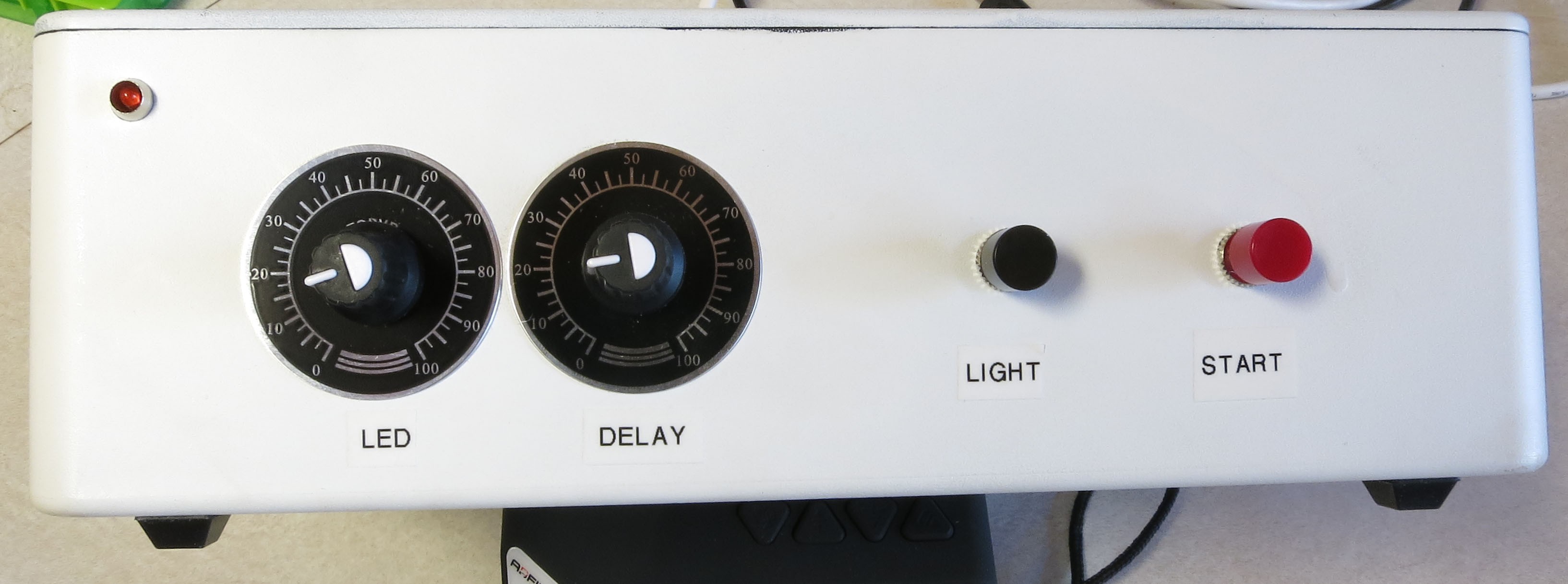
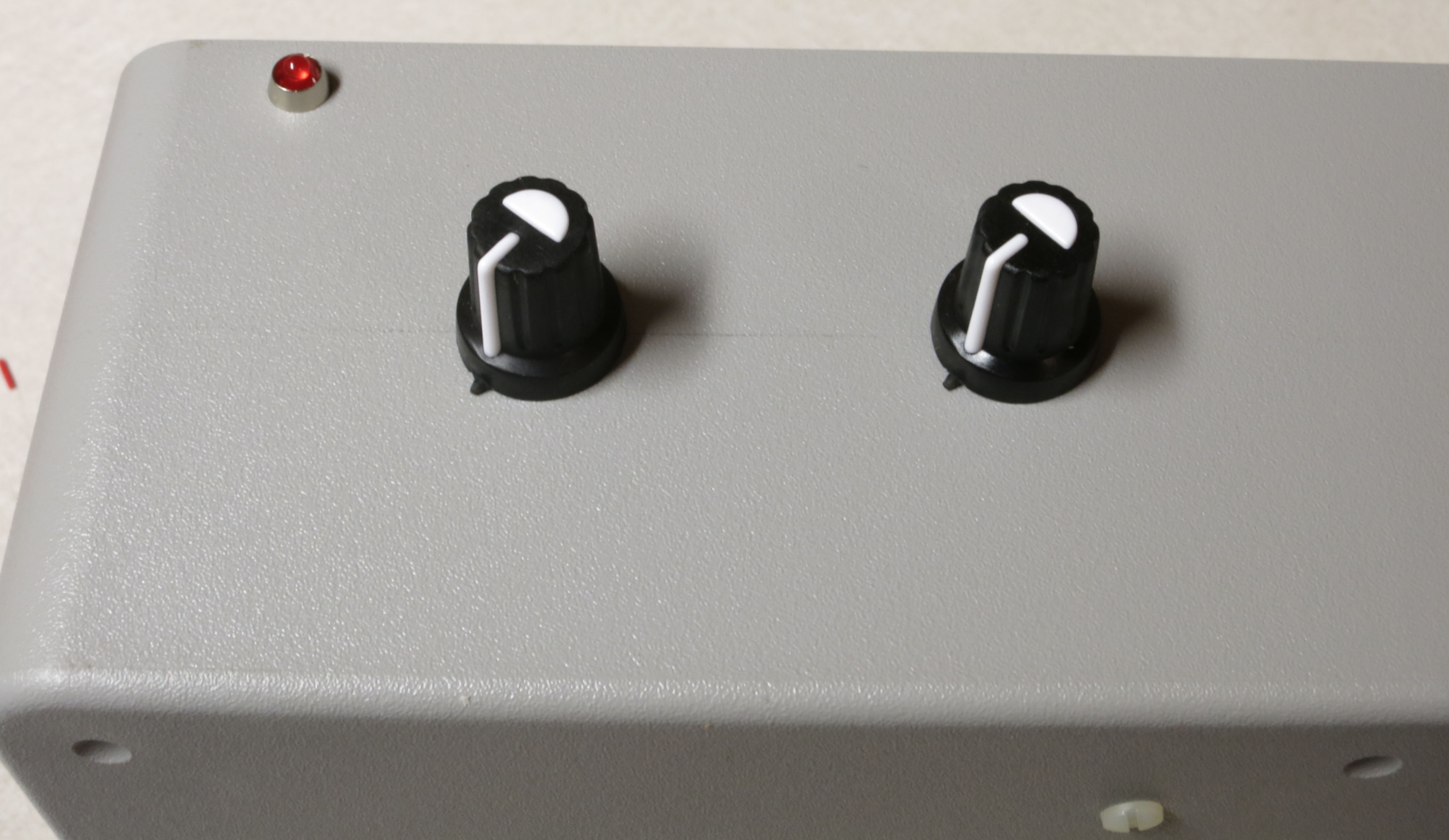
For my previous builds, there were 5 objects to be installed on the front: two 10K potentiometers, two push-button switches, and one LED power indicator. Here’s the front panel of one of my previous builds:
![]()
For this build, I’ll be including one more component, the OLED display, and modifying the front layout to allow space for this. If you choose not to install the OLED, you should use the layout above.
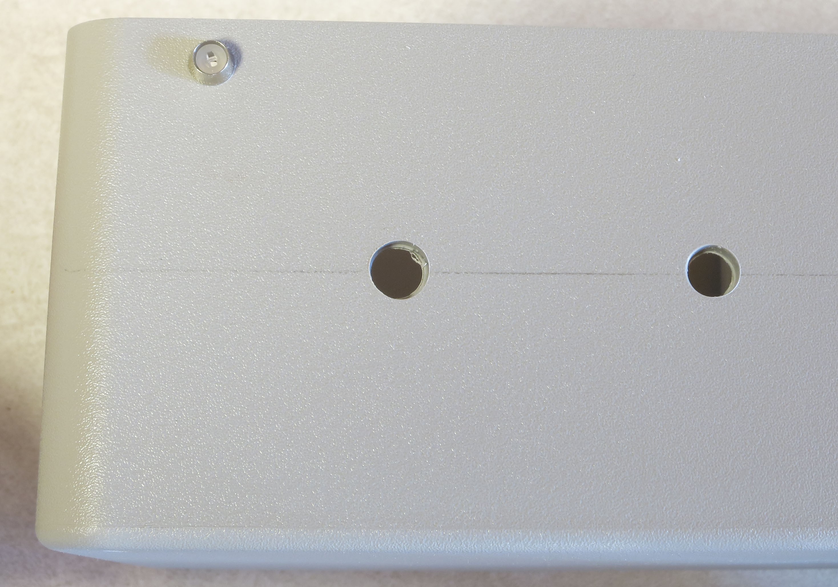
First, mark two drill holes on the left-hand side for the two 10K potentiometers:
![]()
Measure the size of the potentiometer knobs, then drill holes at the mark just large enough for the potentiometers to fit through. Although this plastic is soft enough for regular drill bits, I recommend using a narrow step drill for all large drill holes coming up – it makes a cleaner cut through the plastic, and if you drill the hole too small, you don’t have to change the bit to drill a larger one. After drilling the holes, check to make sure the potentiometers fit:
![]()
Next, drill a hole in the upper left hand corner for the 3mm LED holder, then install it to check for the right size. Make sure you’re not too close to the top, otherwise the lid may not fit on; I put my hole in a just barely acceptable position:
![]()
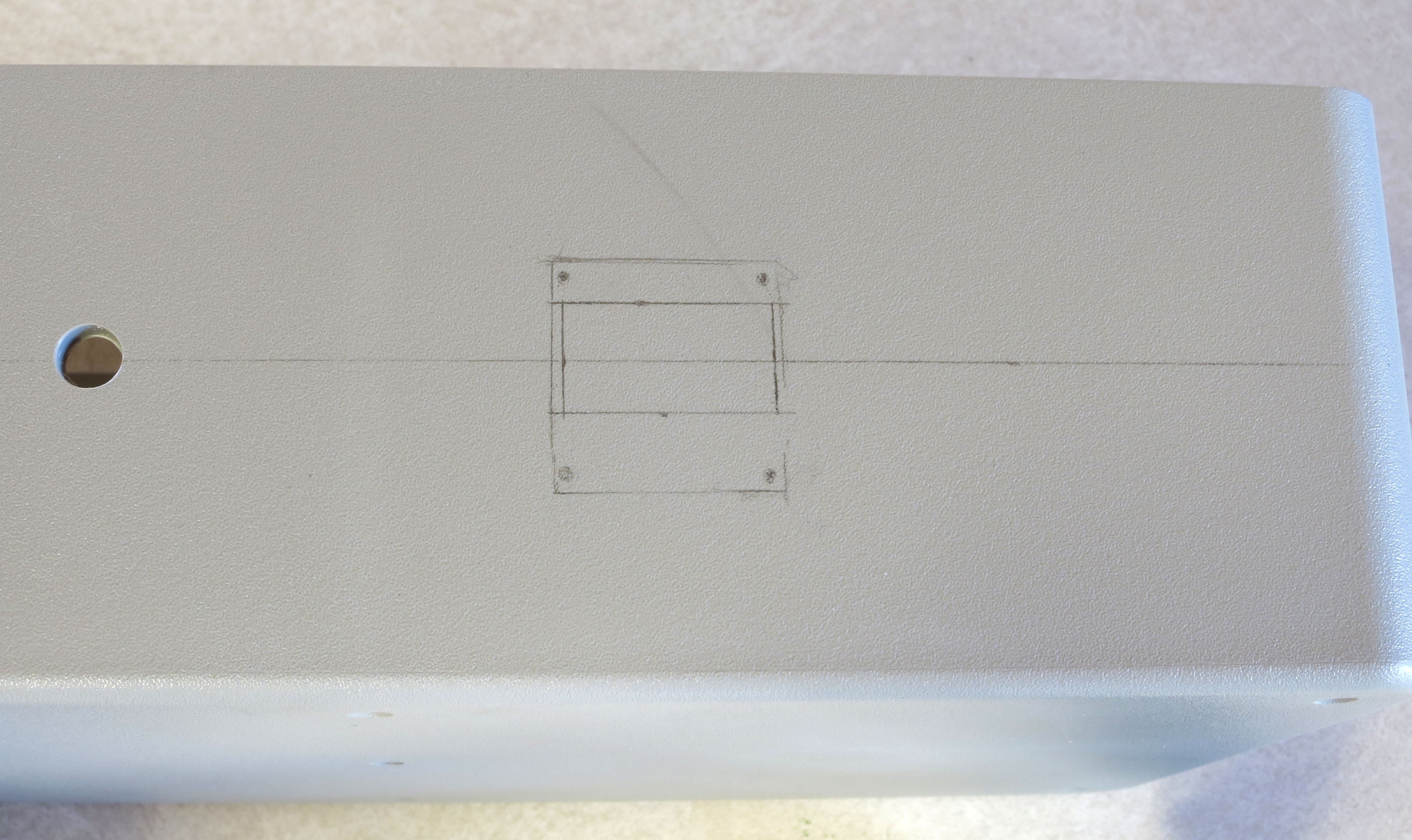
Moving to the right side, if you’re installing the OLED display, you’ll need to mark the location of both the cutout for the main display (which you determined in an earlier step), and the screw holes that will hold the display in place. My approach was to place the OLED display in what I thought was the best position, then trace around the outside of the display board (also marking the positions of the screw holes); I then marked the area I needed to cut out of the box face to have the display part of the board visible:
![]()
Now, a brief diversion into cutting rectangular holes into the box, since you’ll have at least three of these (for two Ethernet panel jacks and one USB panel jack), four if you install the OLED display. If you Google “cut square holes plastic”, you’ll come up with lots of suggested techniques. Here are my suggestions:
- Go through the rest of these instructions, and mark the positions of the cutouts. Then find a friendly woodworker or machinist, and ask them to make the cutouts. Should take them less than five minutes, and the cutouts will look great.
- Drill as many and as large holes as possible within the limits of the cutout, then use a sharp utility knife (boxcutter) to trim out the remaining plastic, and square off the edges.
- I used a variant of the above technique, but used a Dremel rotary tool with a 561 cutter to remove the bulk of the plastic and trim towards the edges. USE SLOW SPEEDS! I then used a utility knife for the final finishing work.
- If the plastic is less than 1/16” thickness, you can use a “nibbler” to cut out most of the plastic after drilling a starting hole. However, the plastic in the Polycase box is too thick for a nibbler (I know this for sure – bought a nibbler, then found out it wouldn’t work on that box).
If you’re doing this yourself, but have never done it before, one suggestion would be to do the other three cutouts first for practice. They’re on the sides and back, so if they look bad when you first do them, they won’t be as noticeable as the one on the front.
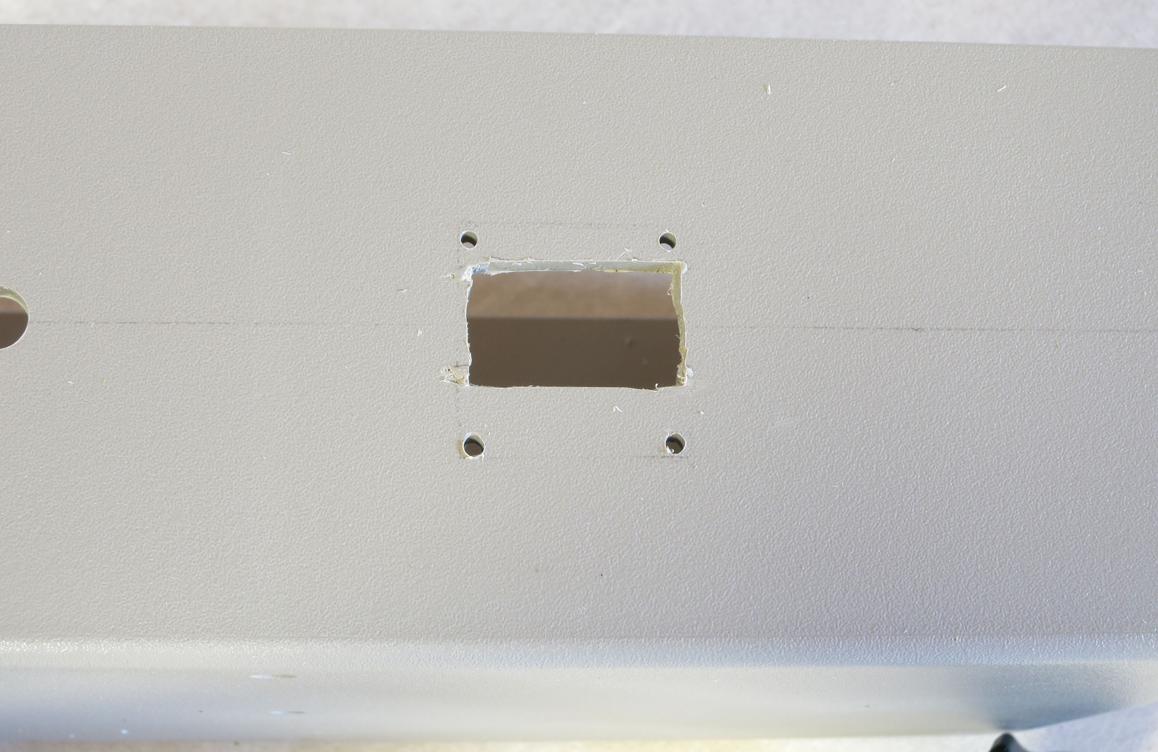
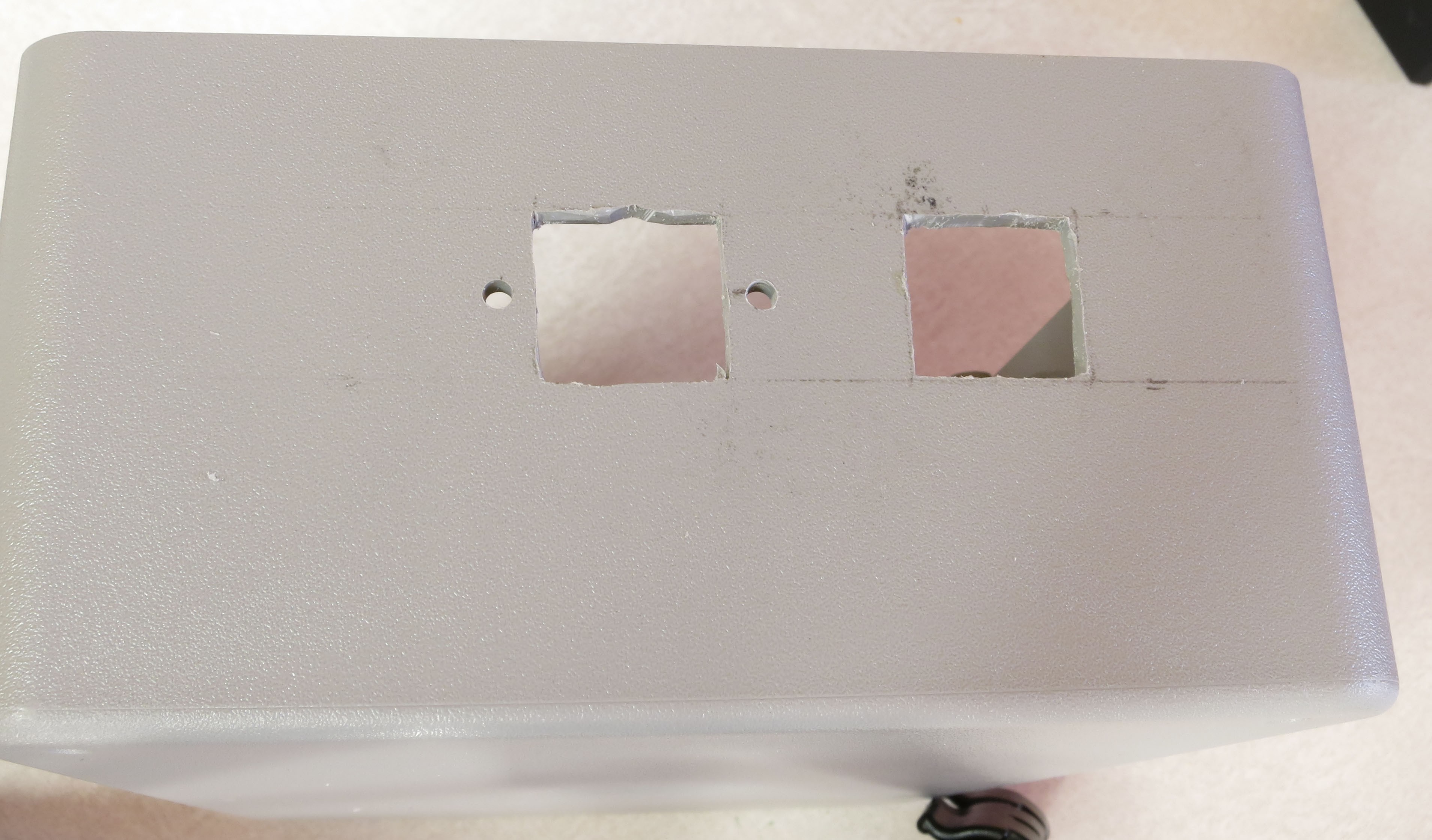
I went ahead and did the front cutout first (along with drilling holes for the screws):
![]()
Doesn’t look great in this picture, but I went back and cleaned it up a bit with a utility knife, so the final version looks better.
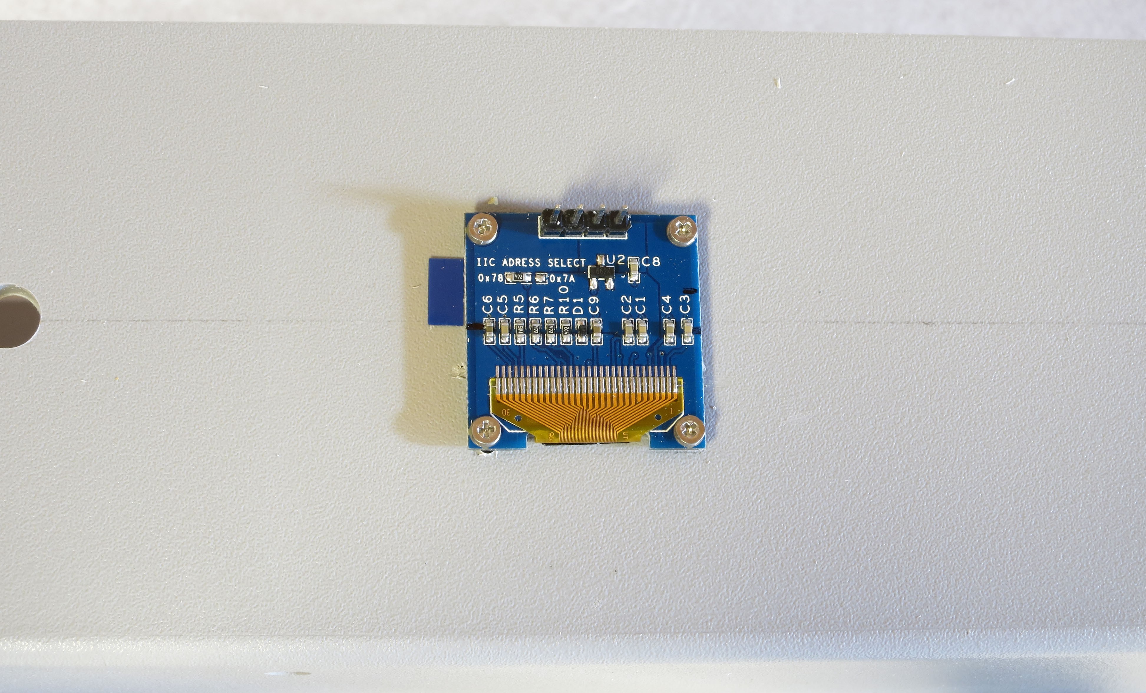
To make sure the screw holes were drilled in the right place, put the display on the box over the cutout, and insert the mounting screws to make sure they fit and are in the right place. If they don’t fit exactly, drilling the holes one size larger may fix the problem. I used #1 screws/nuts to hold the display in place:
![]()
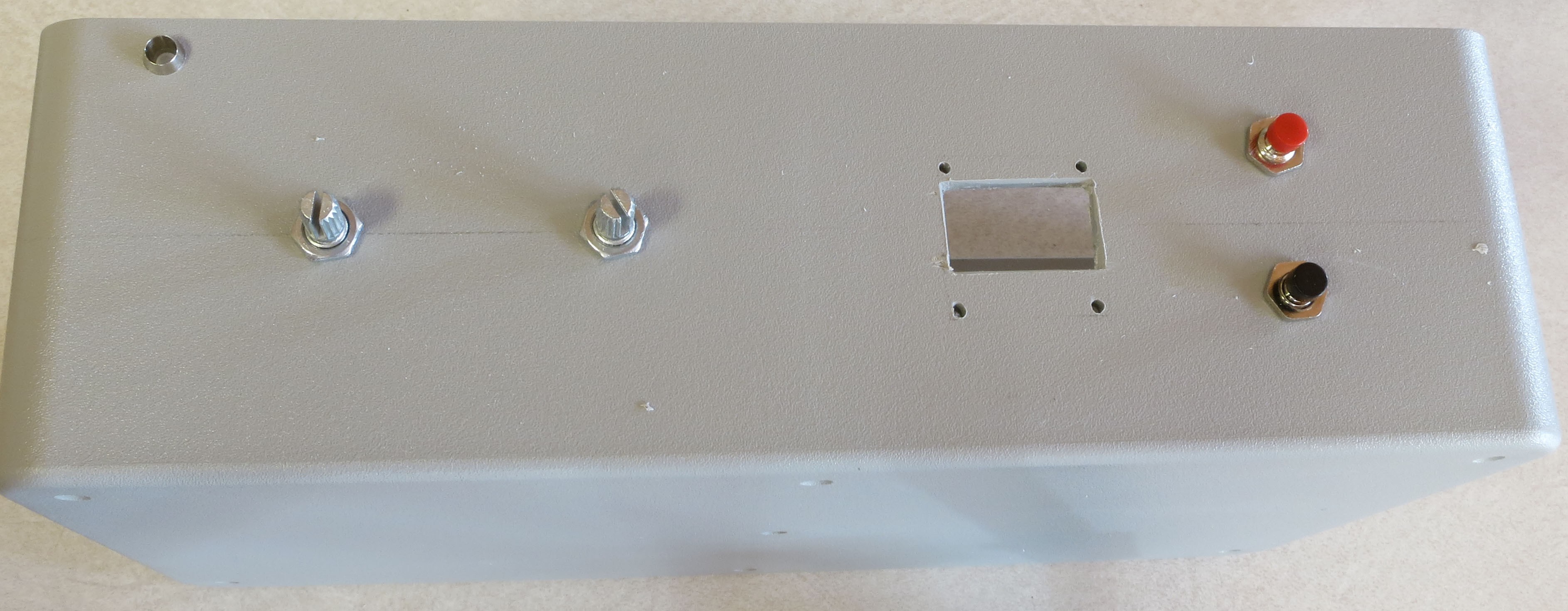
Next, drill holes for the two front panel pushbuttons, and check to make sure they fit; these control modes of turning on the LEDs:
![]()
That’s it for the front panel; remove all the installed parts for now.
Next is the right side panel; you’ll need to make two cutouts for the Ethernet panel jacks. Your natural inclination may be to put them near the bottom, but if you do, the CAT4101 driver board will block installation of the panel jacks. Here’s where I marked the positions for mine:
![]()
The top edge of the cutout is 2 cm below the top of the box, the right edge of the right cutout is 3.5 cm from the back edge of the box, the cutouts are 2 cm x 2cm in size, and are spaced 2 cm away from each other. Cutting them out:
![]()
Grab one of the Ethernet panel jack cables, and measure the distance between the two screw holes. Drill two holes that distance apart evenly spaced on both sides of the cutout horizontally, and in the middle of the cutout vertically:
![]()
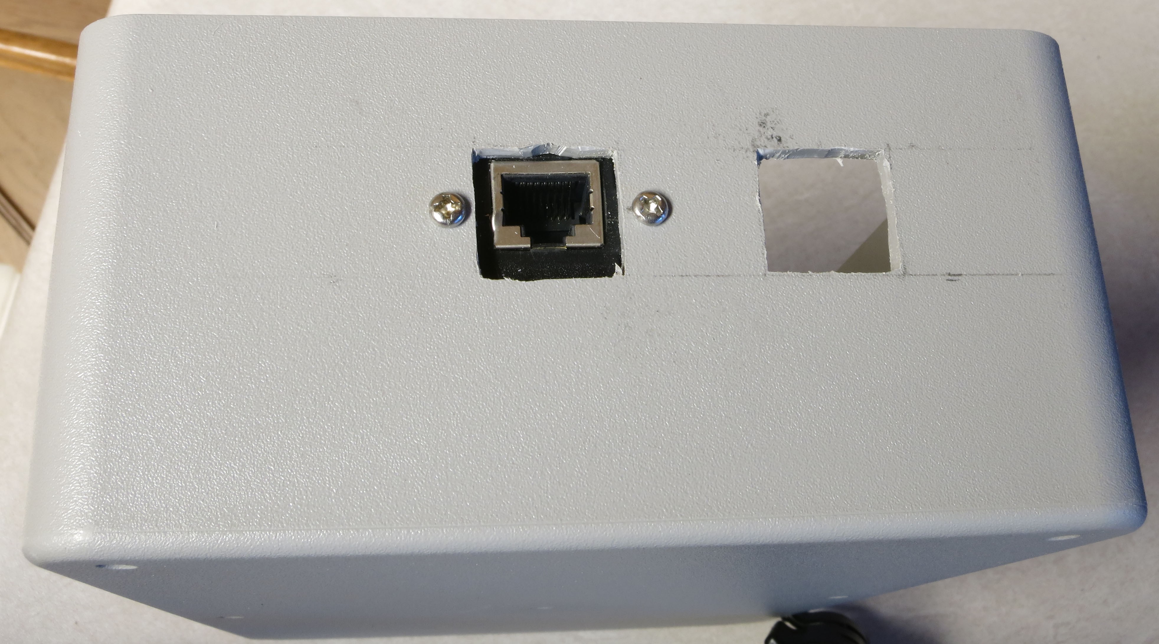
Install one of the Ethernet panel jacks to make sure it will fit:
![]()
![]()
Drill holes in a similar position on the other cutout, and do the same check to make sure the panel jack will fit:
![]()
![]()
Remove the panel cables for now.
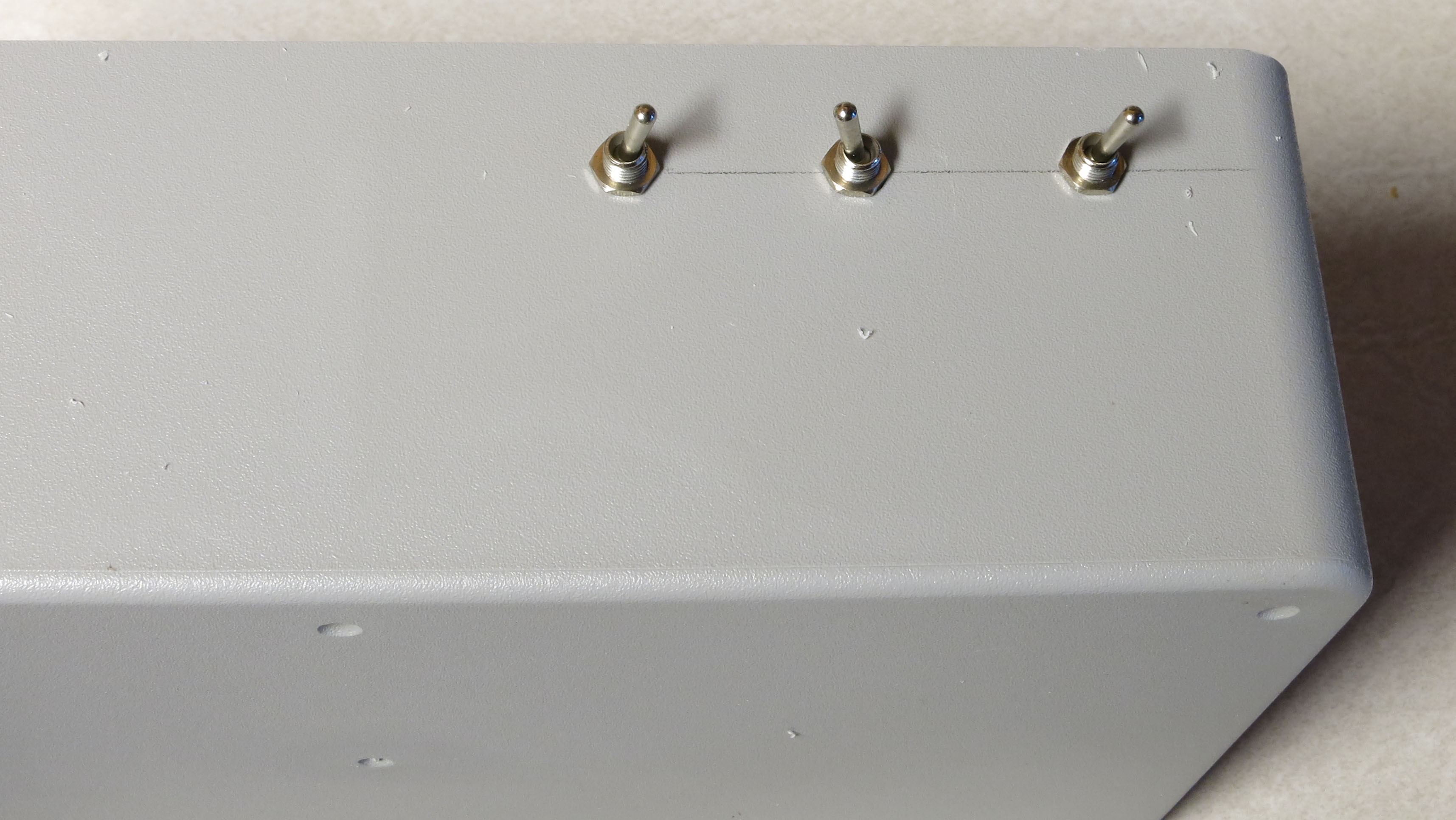
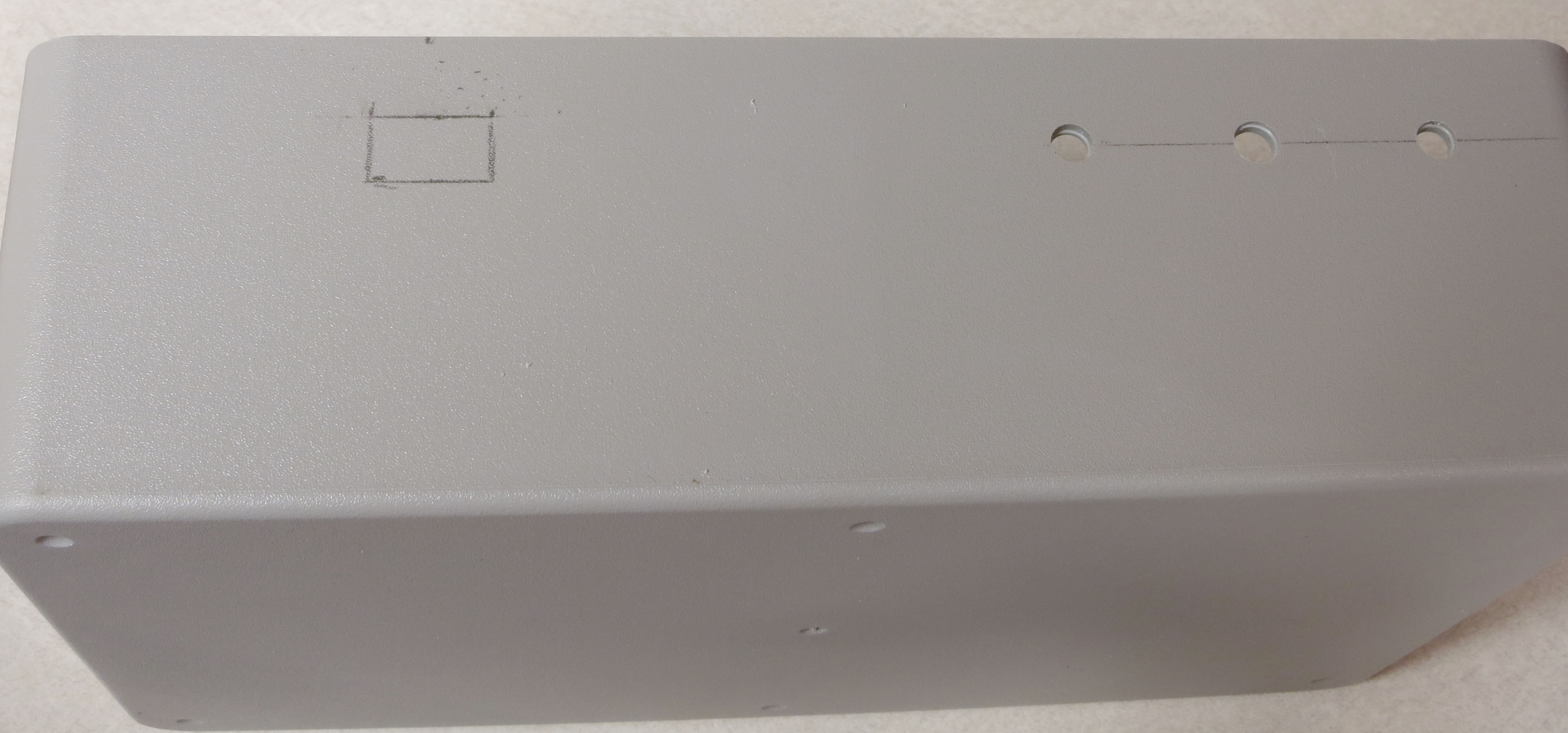
You’re done with the right side of the box, now move on to the rear. Drill three holes on the upper right side for the three toggle switches, then install them to check the fit. The pencil line is to make sure they were all neatly on the same horizontal line, spaced about the same distance apart:
![]()
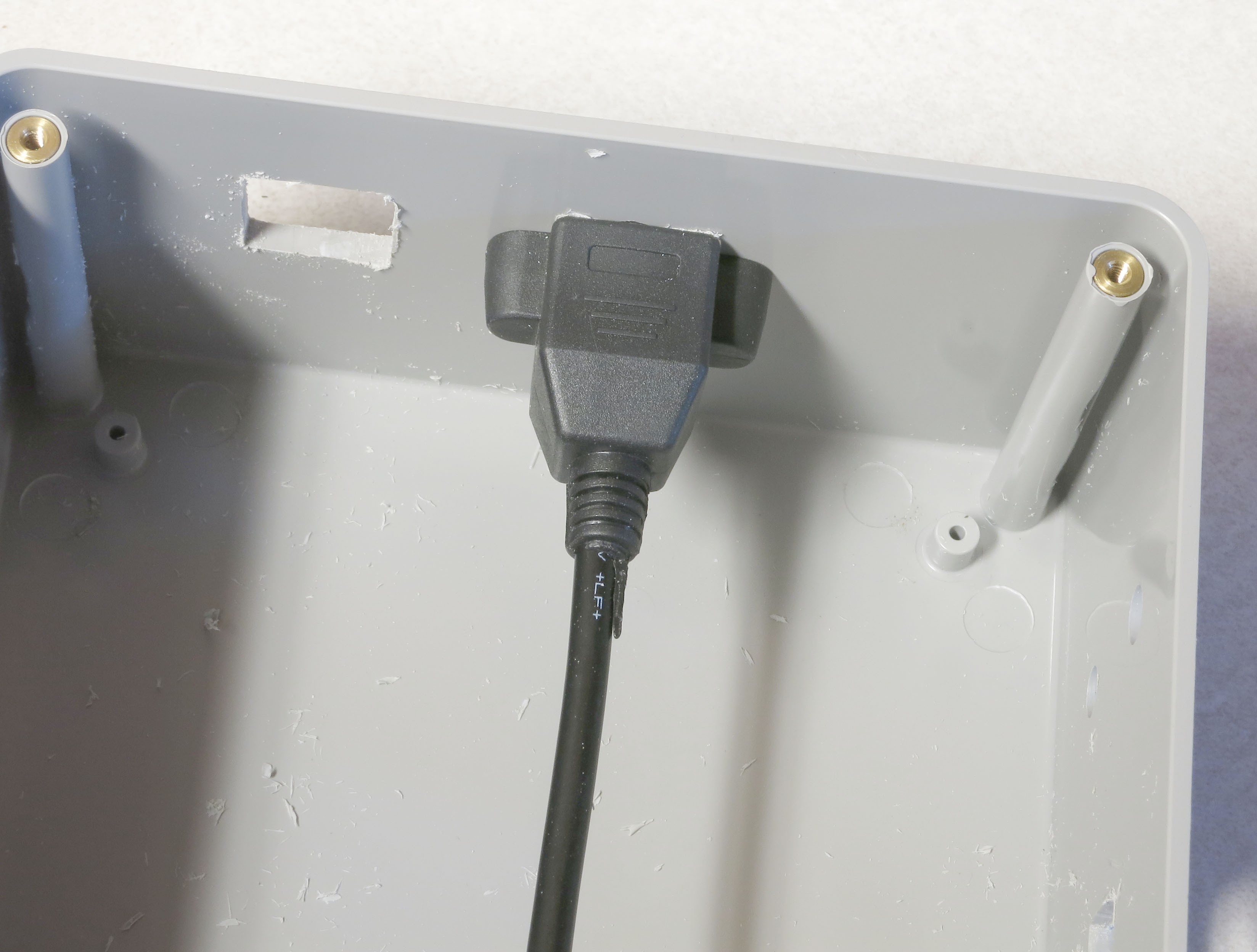
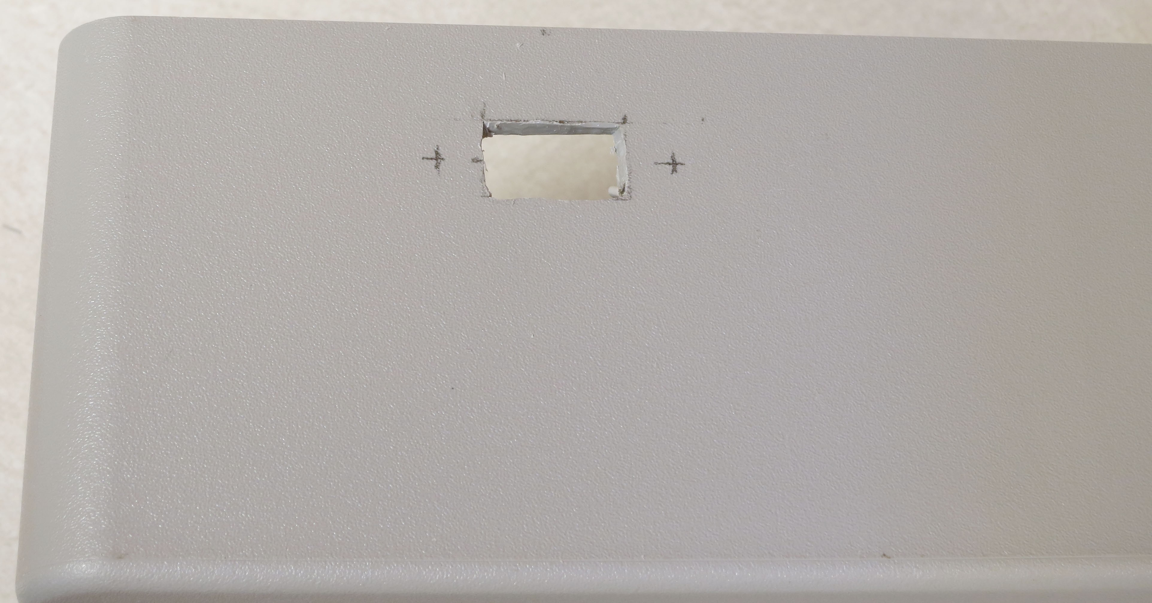
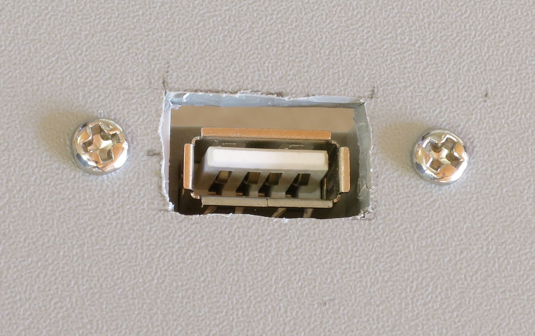
On the upper left side of the rear, mark a cutout for the USB shutter control cable about 1.8 cm wide and 1 cm high. You should position it about 1.5 cm below the top edge, to make sure it clears the electronics when the system is full assembled.
![]()
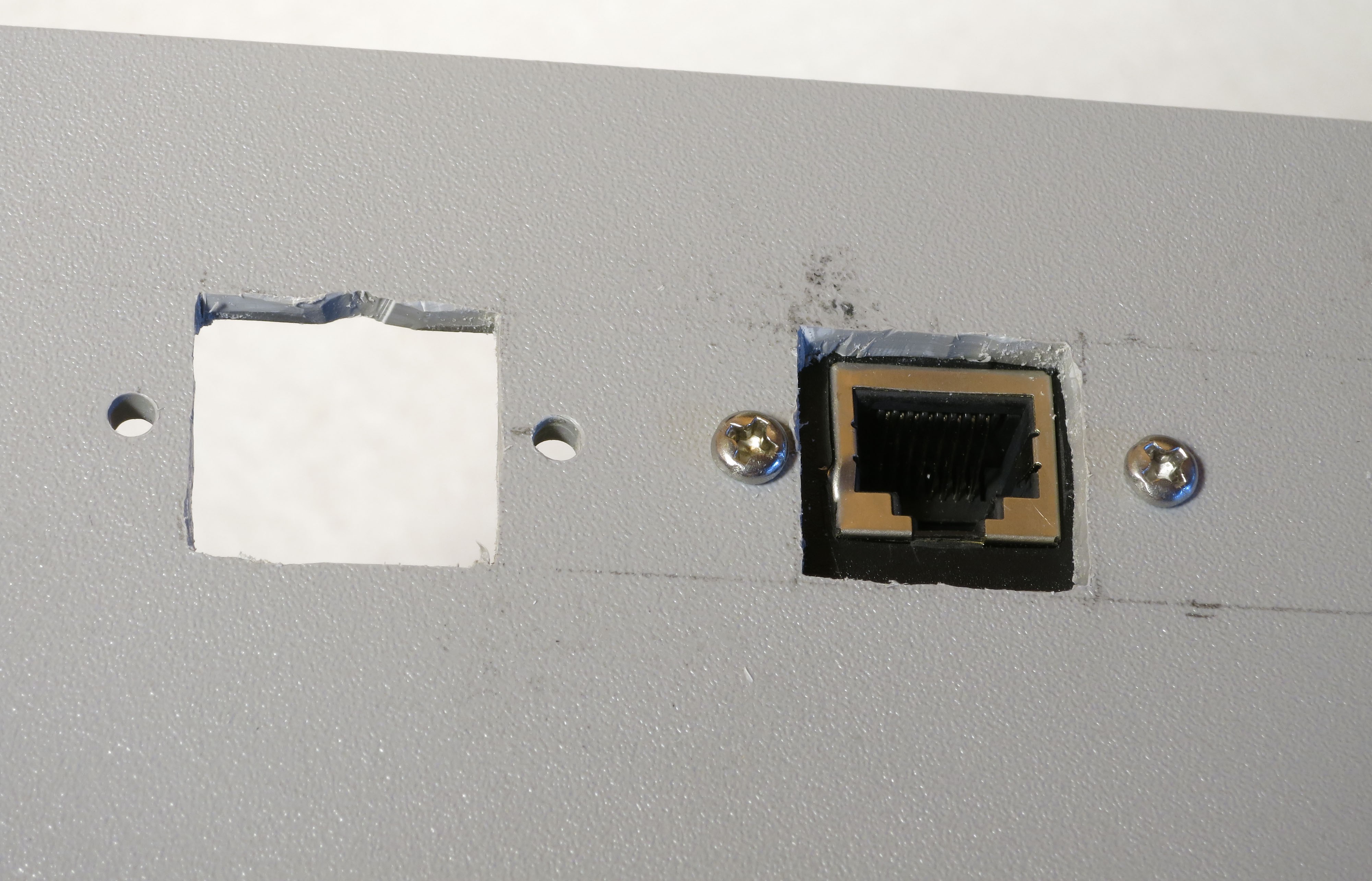
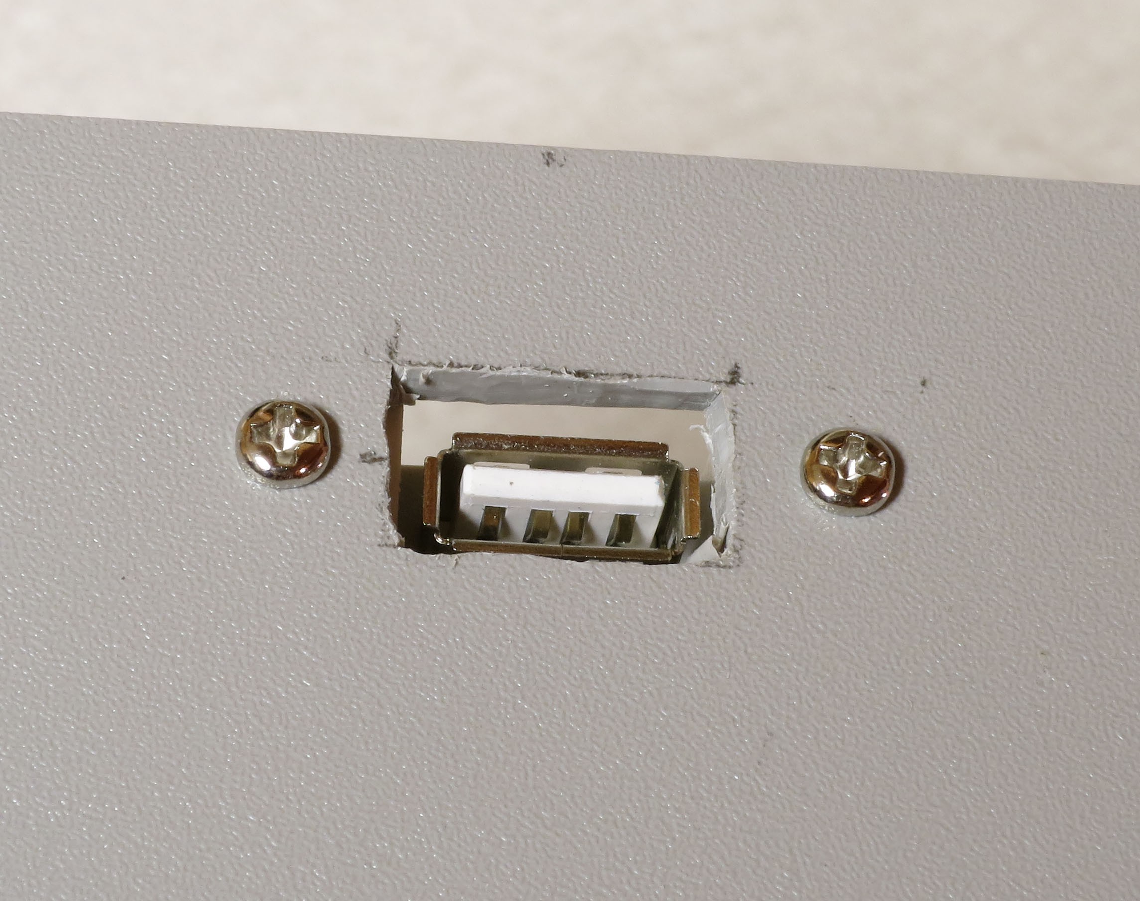
Cut out the plastic, drill two holes for the USB panel jack screws, then attach the USB panel jack to make sure it fits:
![]()
![]()
![]()
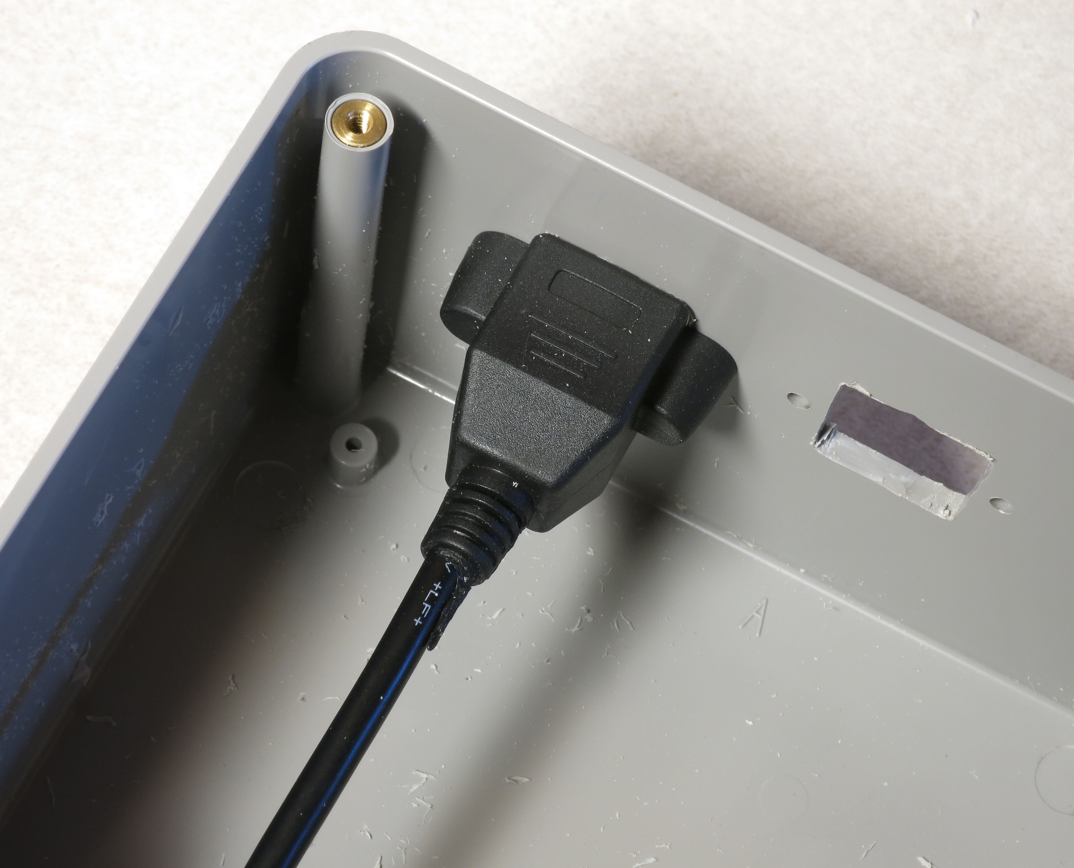
To make sure the cutout is big enough, and the panel jack is positioned correctly, grab a USB cable and check to make sure you can insert it fully into the jack.
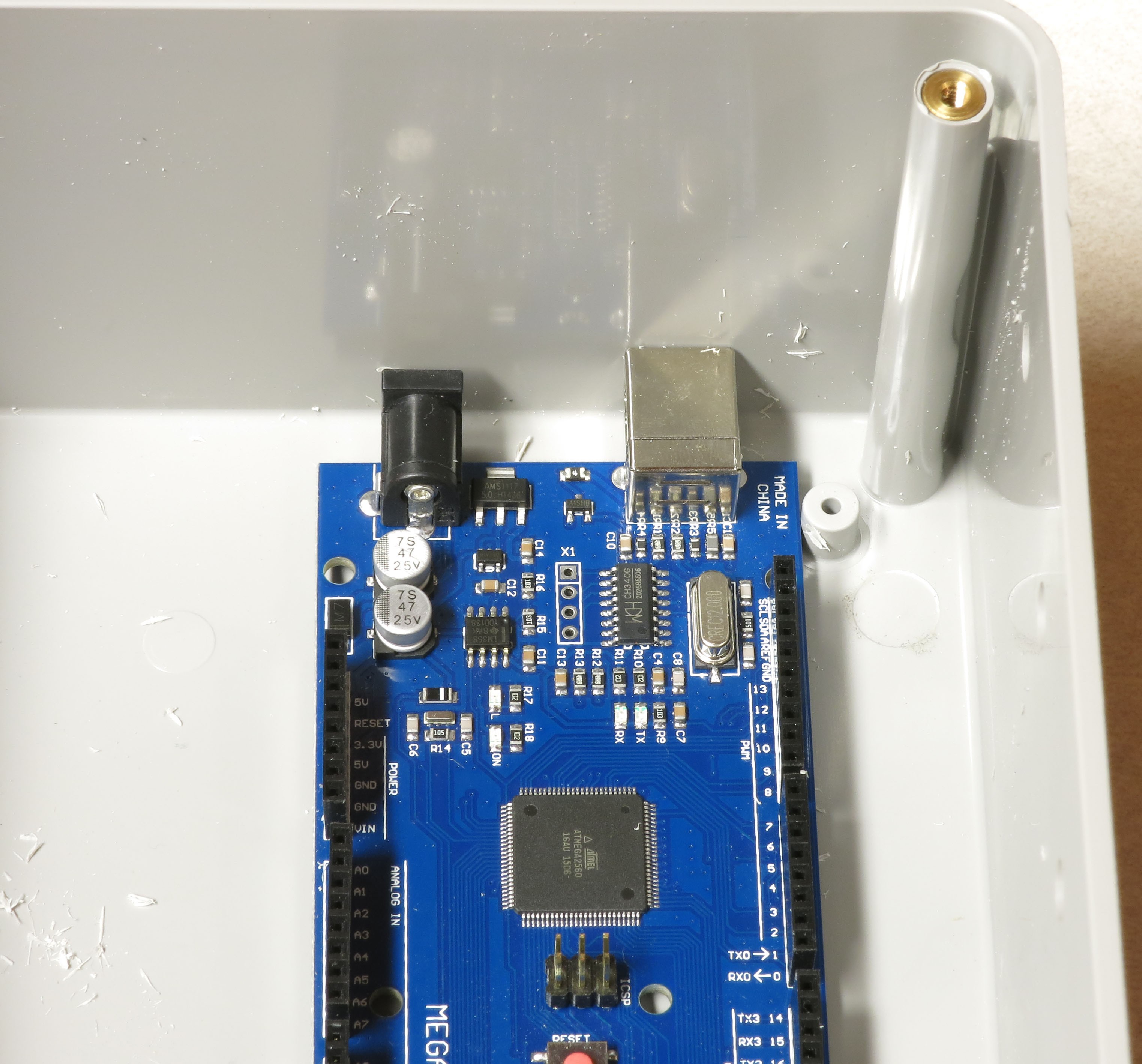
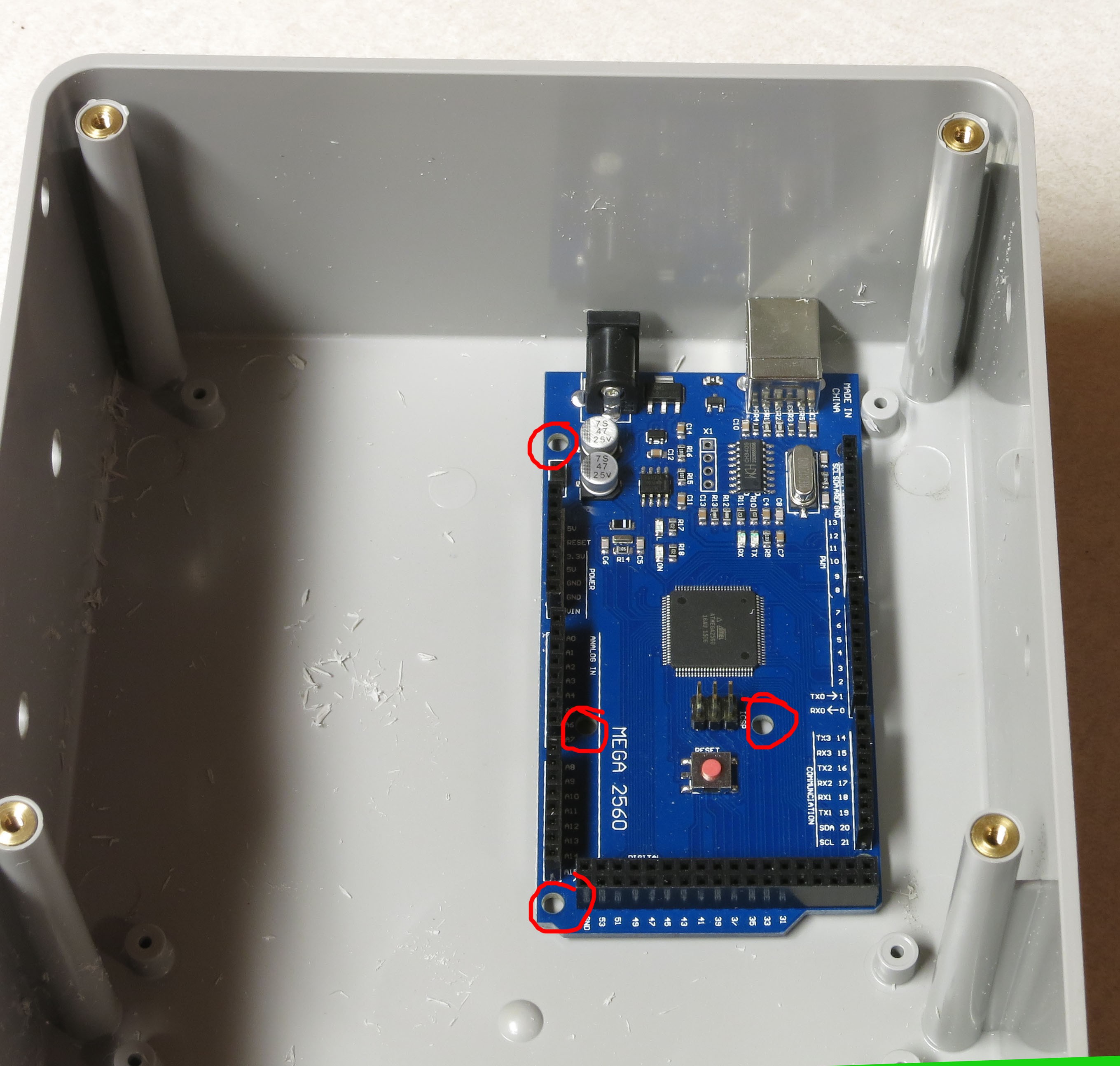
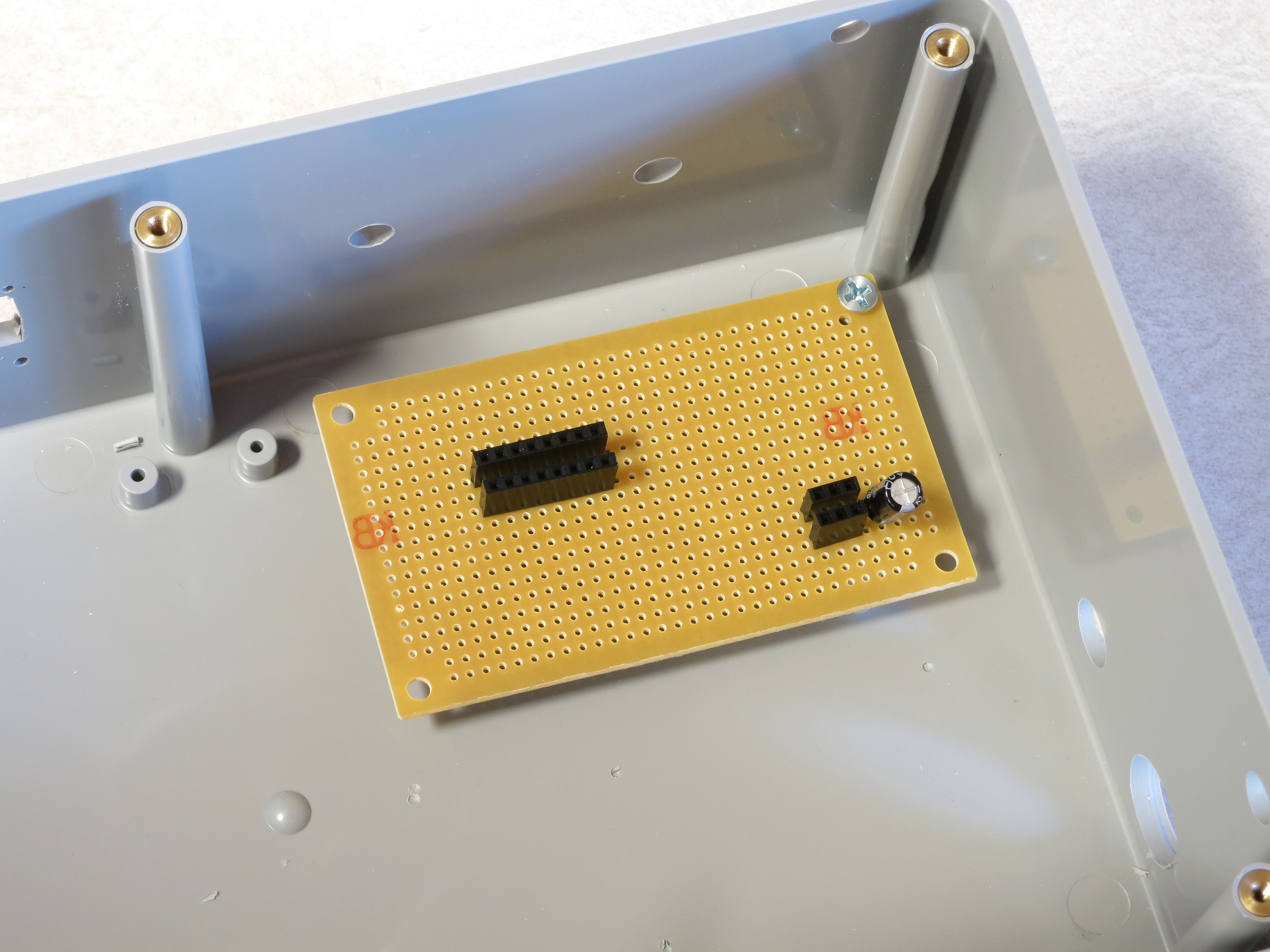
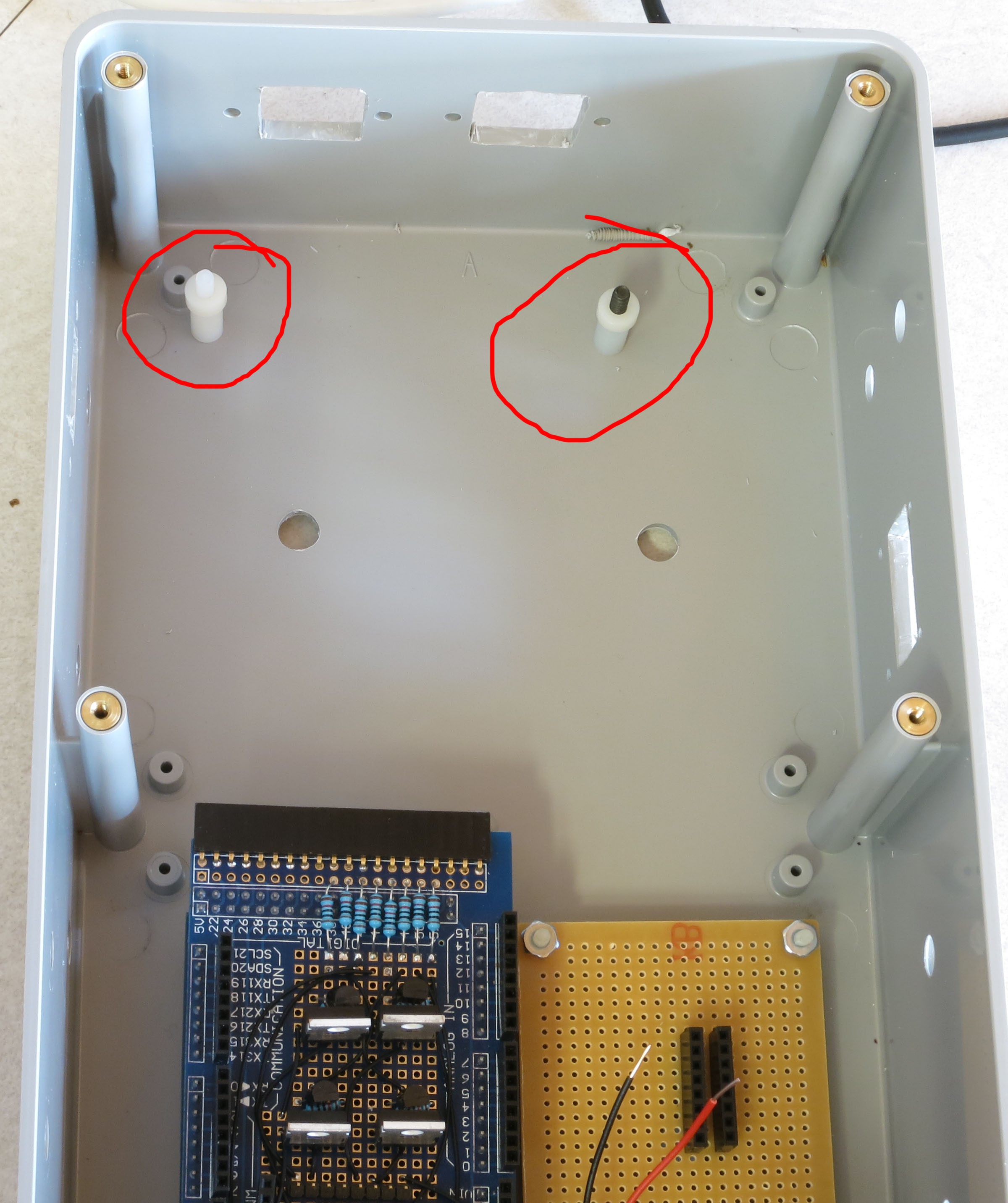
Next, take your Arduino Mega, and slide it into the rear left corner so that the USB jack is flush and square against the left side of the box, and the top edge of the Arduino is flush against one of the short PCB screw posts at the bottom. All the edges of the Arduino should be parallel to the nearest edges of the box:
![]()
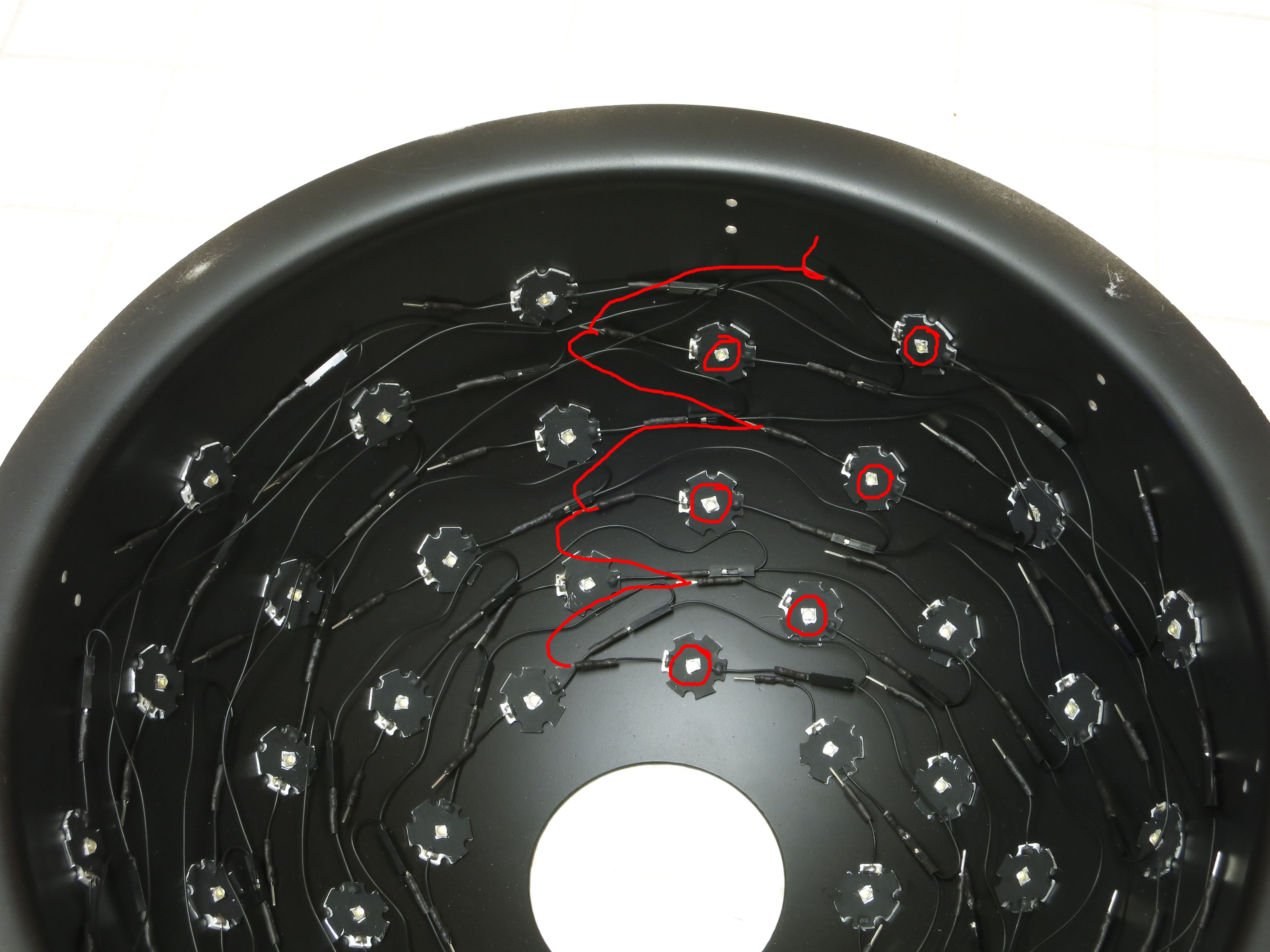
Grab a drill bit that will fit into the holes in the Arduino PCB board, push it through the 4 holes indicated in the picture below (circled in red), and twist it to make a mark that will indicate where to drill a hole later on:
![]()
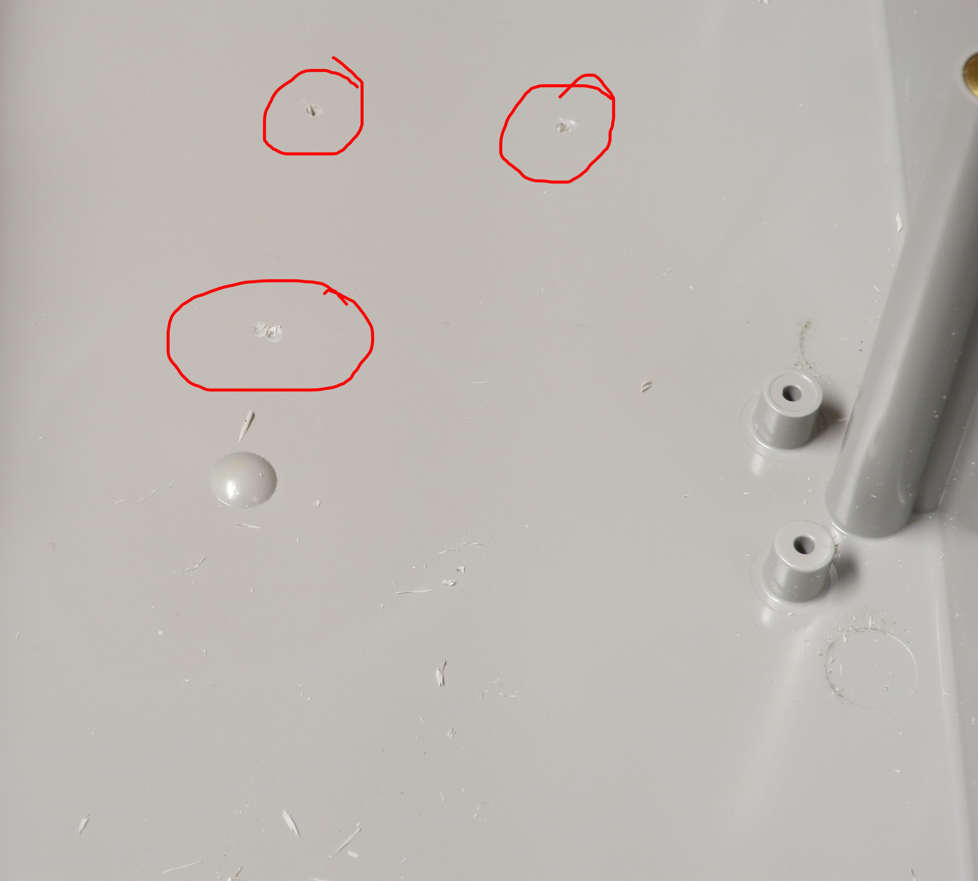
Ignore the two additional holes at the top of the Arduino– they don’t have enough space for a screw or nut to be useful. The picture below shows three of the four drill marks, top one got cut out of the picture by mistake:
![]()
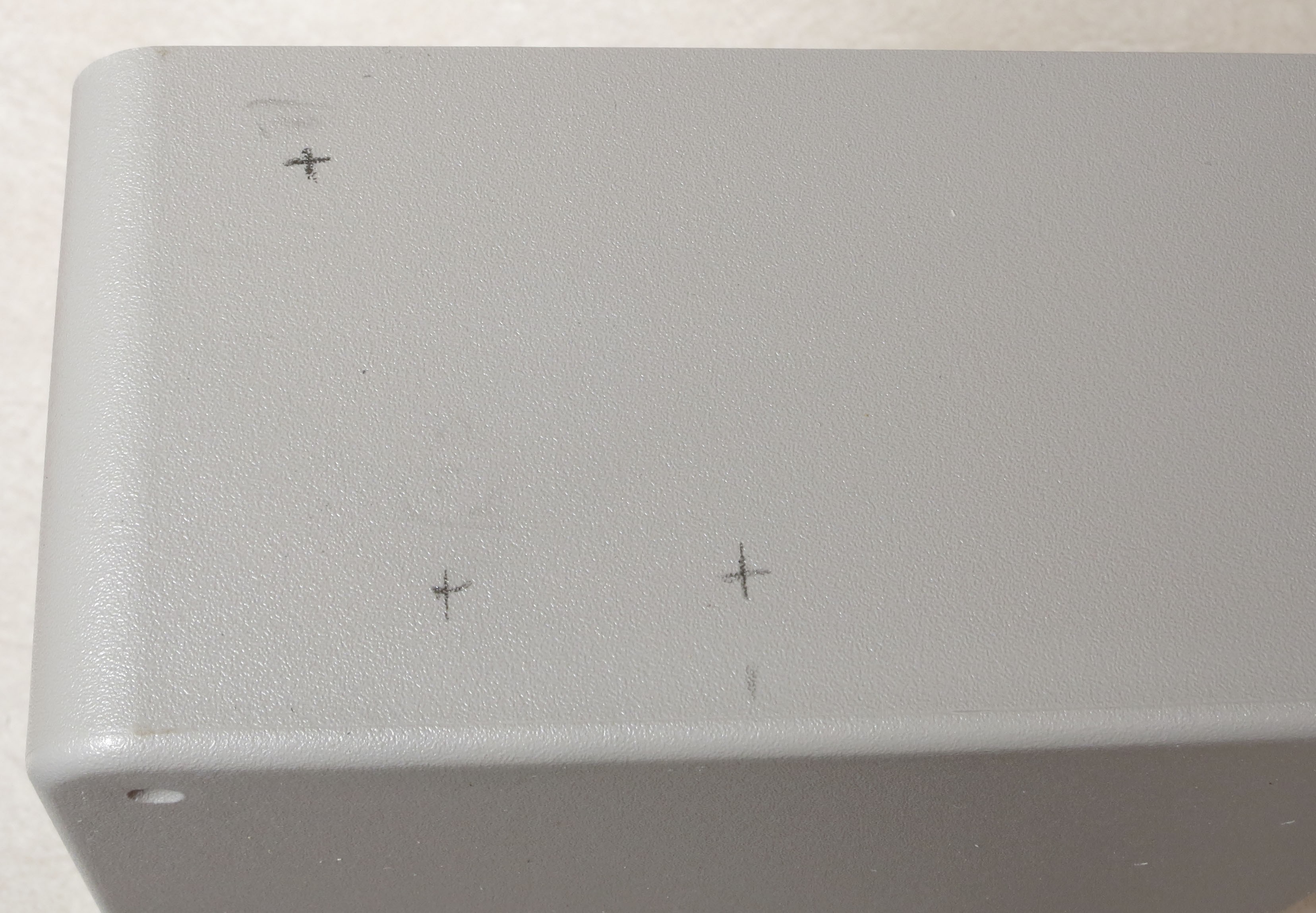
Next, go to the left side panel (the only one left that shouldn’t have any holes in it). You will be drilling three holes. The first, in the upper left, is for the reset button, and exact position isn’t critical – just make sure the button will fit in the hole, and it won’t keep the lid from fitting.
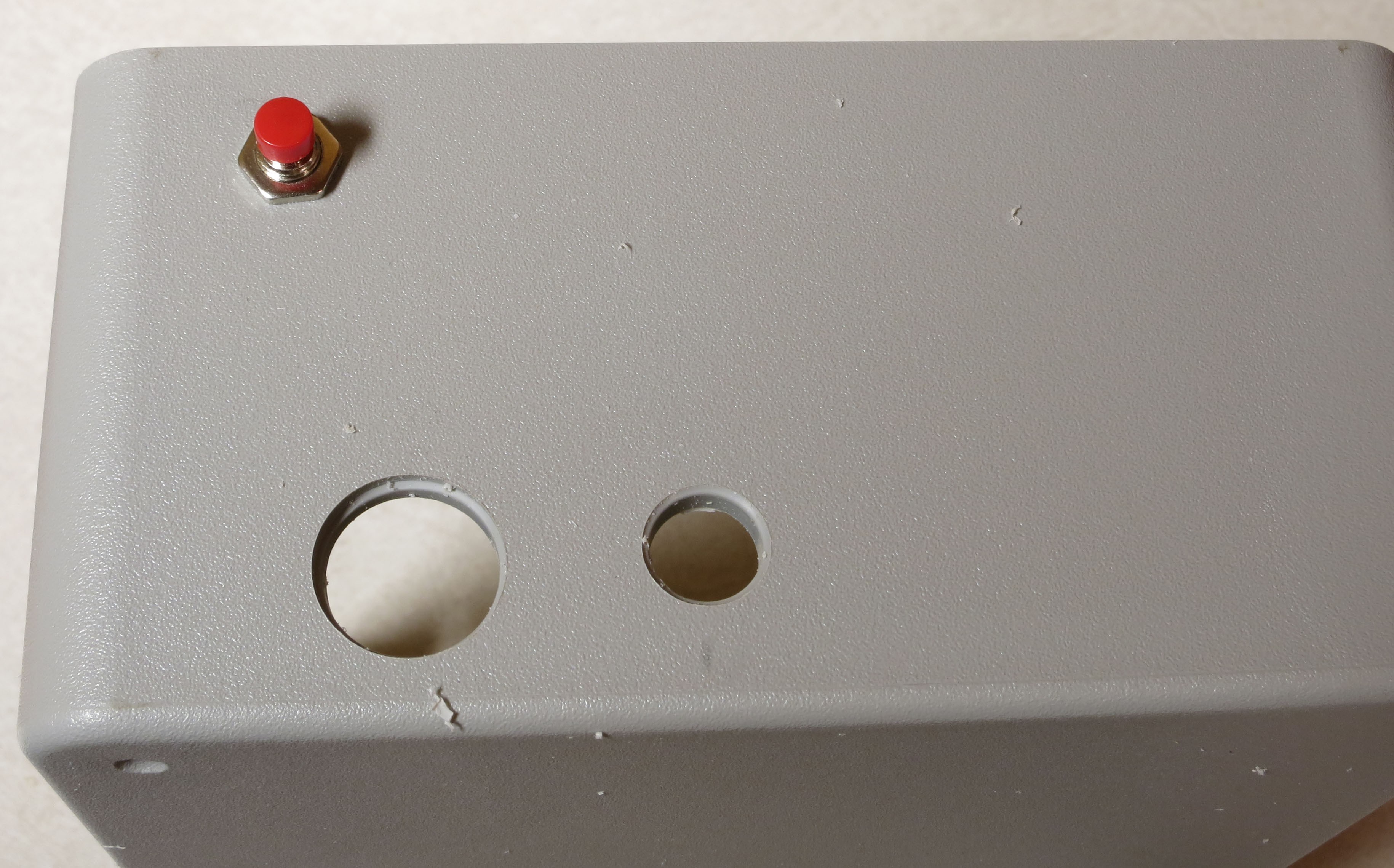
The other two holes are for the Arduino USB jack and Arduino power jack. The one on the left is the USB jack, and the drill mark is 3.75 cm from the back edge (the flat part, not the curved part), and 1.6 cm from the bottom. Drill a hole about ¾” in diameter at this location using a step bit.The one on the right is for the Arduino power jack; make a drill mark 6.8 cm from the back edge and 1.7 cm from the bottom, then drill a hole ½” in diameter.
![]()
![]()
Note: If you drill the two Arduino holes and then stick the Arduino back into the box, it may look like the holes are too high. Don’t worry – you’ll be installing the Arduino on top of spacers that will raise it to the right height.
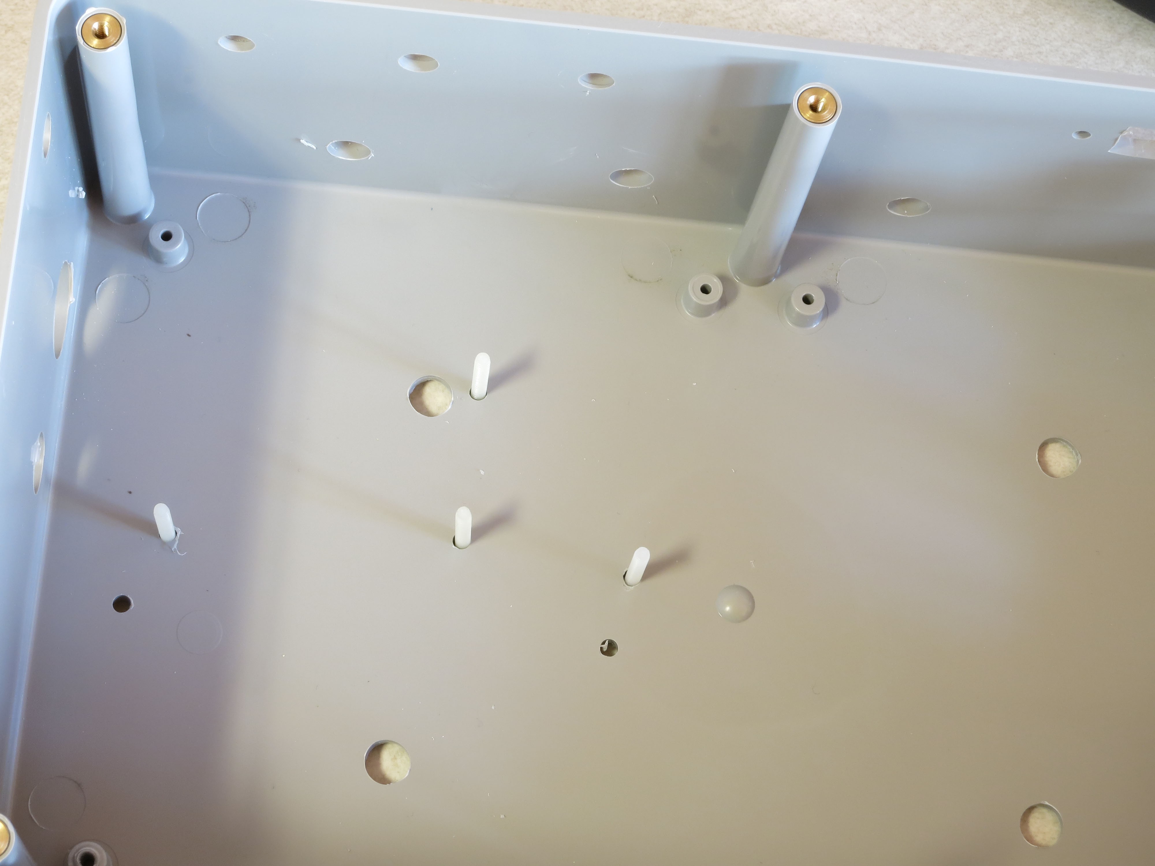
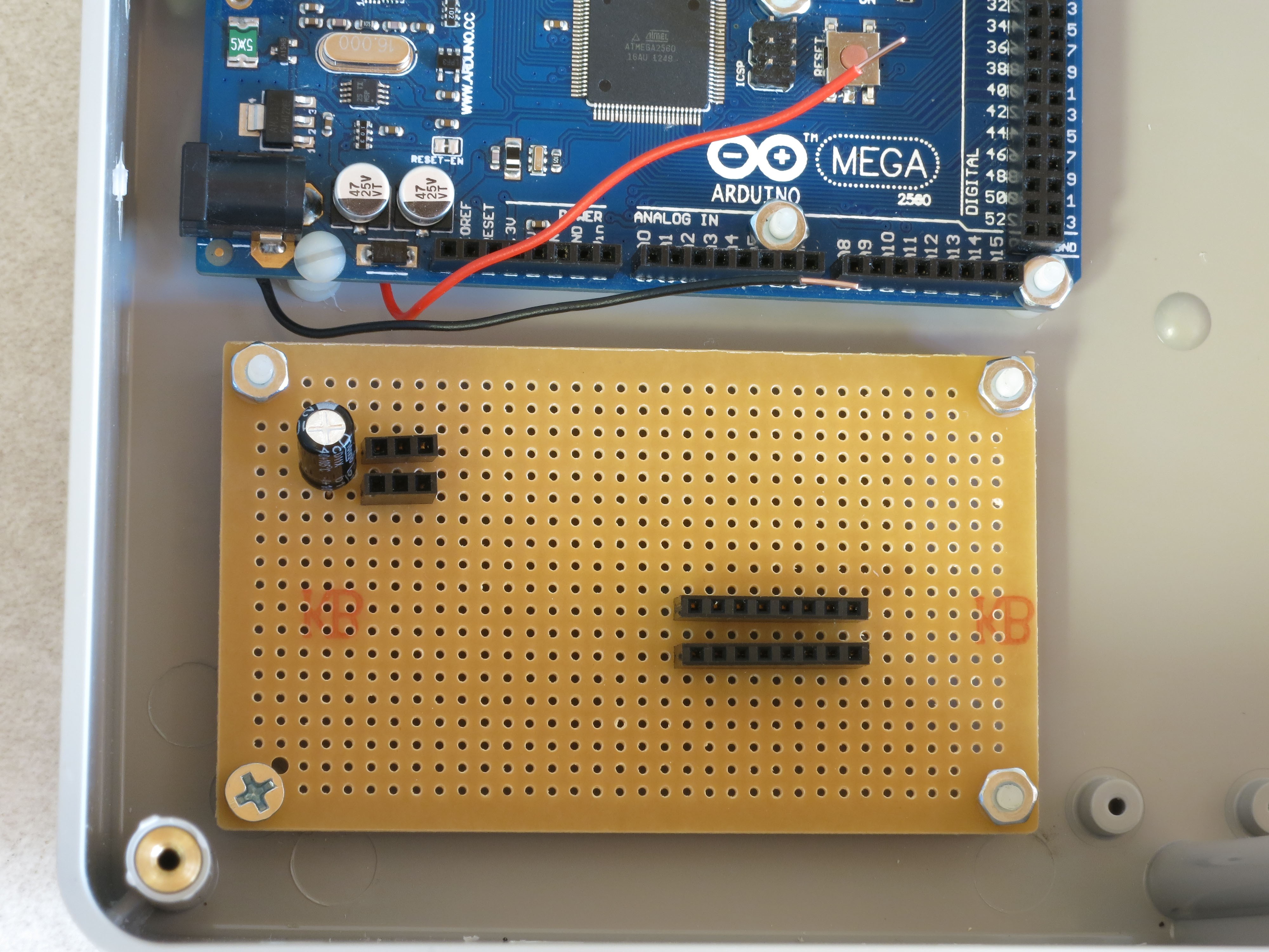
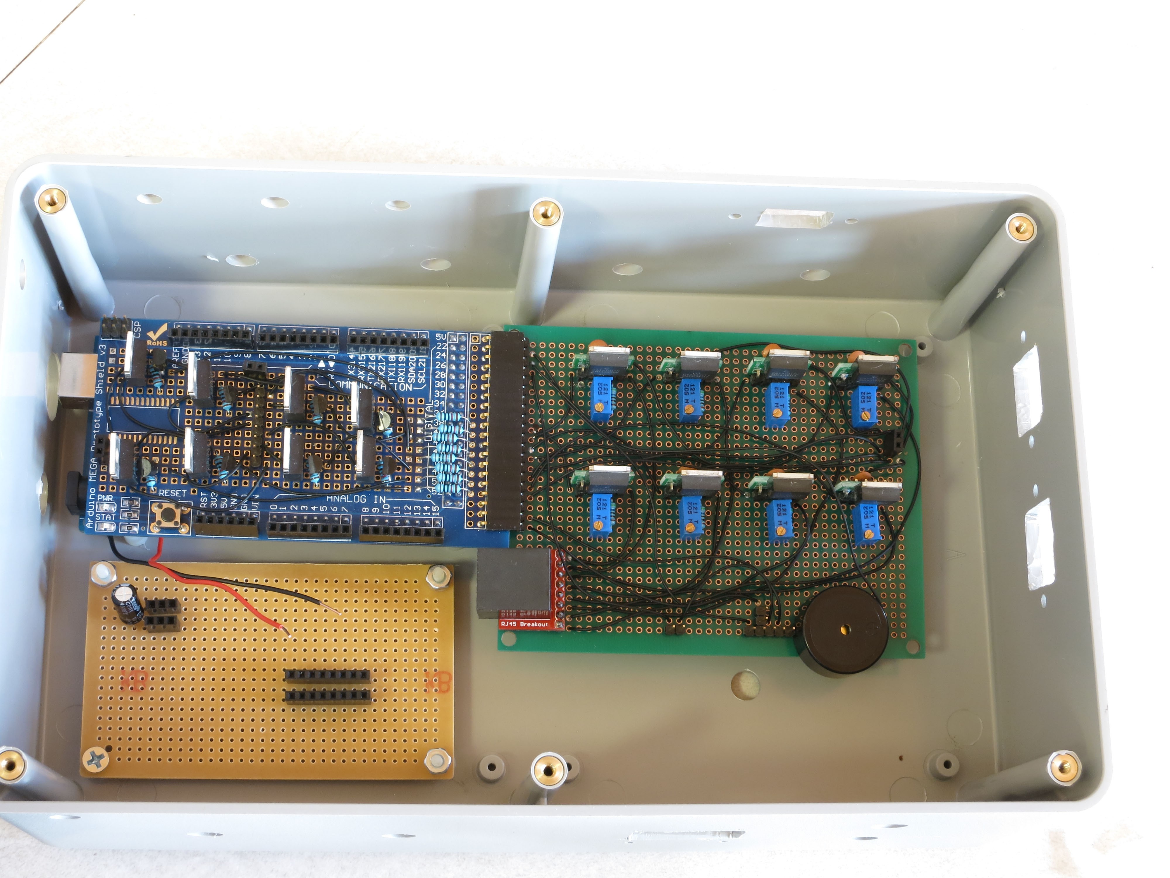
One more set of marks to make on the inside bottom of the box. Install the power strip board using one 4-40 sheet metal screw to attach it to the PCB upright in the front left corner of the box; position it as square as possible:
![]()
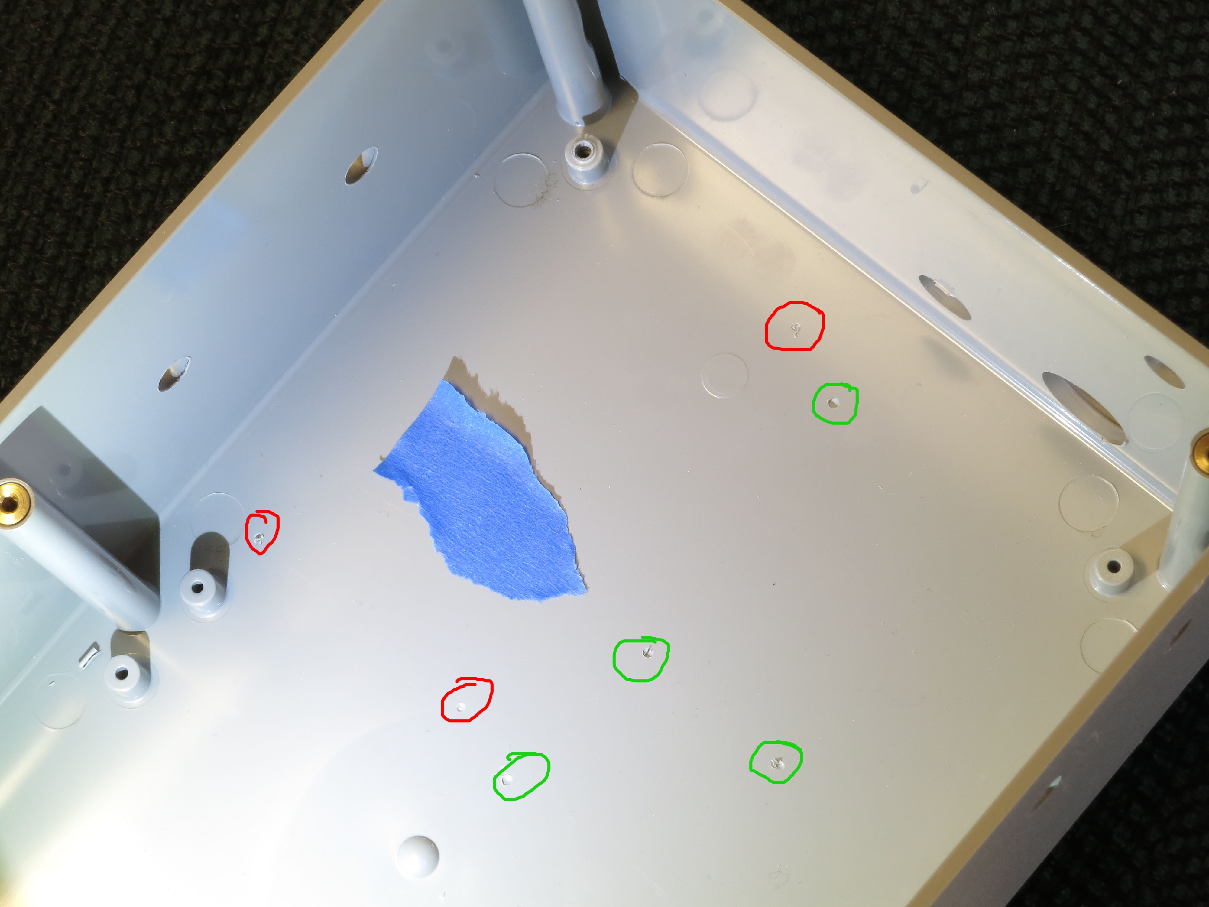
As with the Arduino board earlier, use a drill bit through the open 3 holes of this board to mark a drill position in the bottom of the box directly underneath the board. After removing the board, you should see the following marks, with the power strip board marks circled in red, and the Arduino marks made earlier circled in green:
![]()
The blue masking tape? That had me confused, too, until I remembered that the camera had trouble focusing for this picture due to the lack of detail, and adding the masking tape fixed that problem.
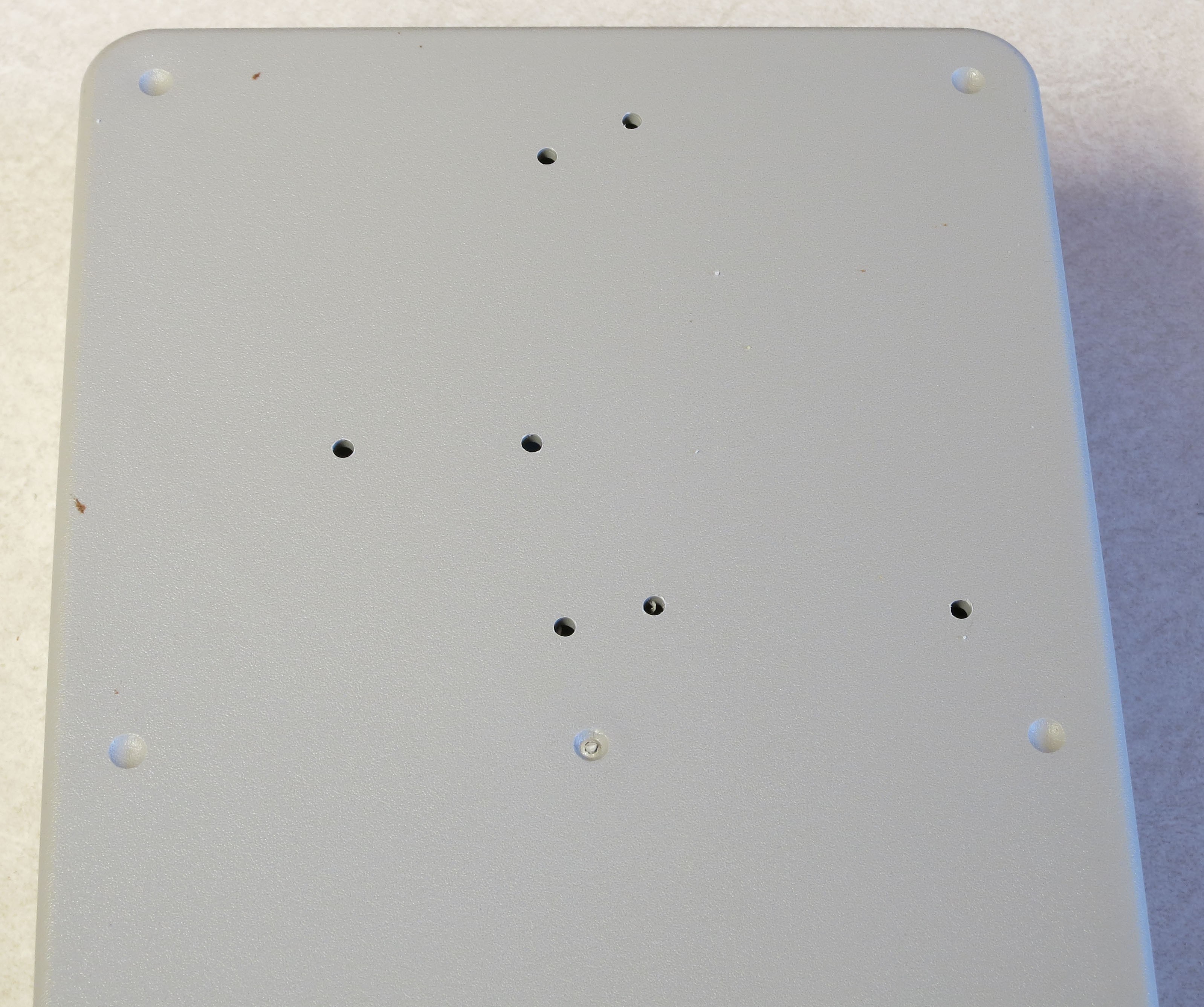
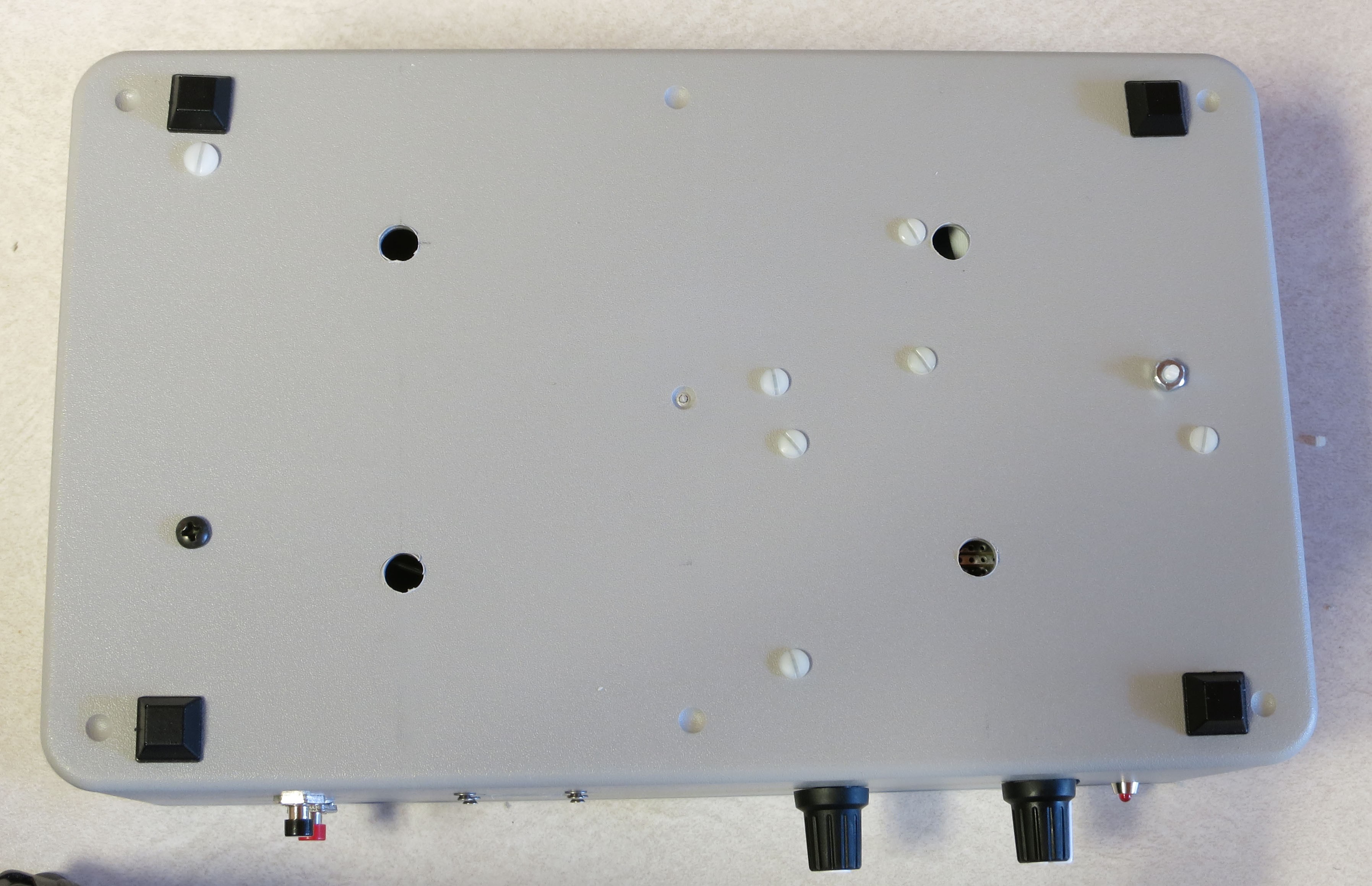
For all 7 drill marks above, drill a hole for a 4-40 screw (or its metric equivalent). The bottom of the enclosure will now look like this:
![]()
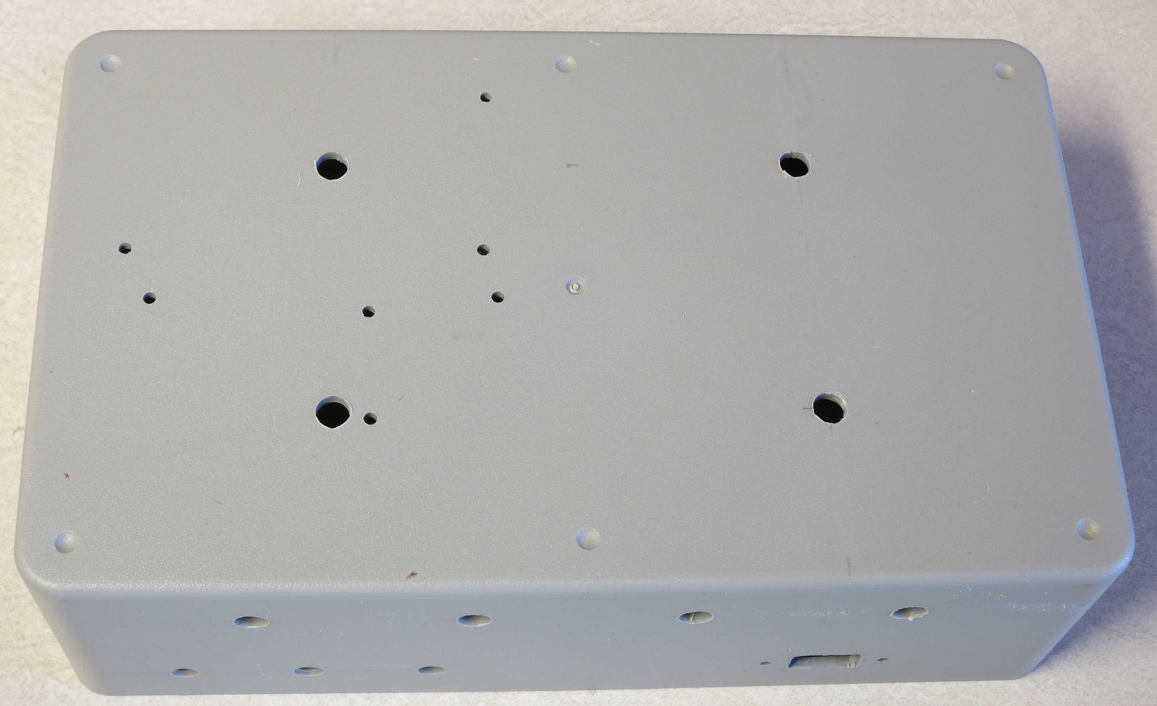
While the system doesn’t consume that much power, and shouldn’t get too hot, I think ventilation/cooling is never a bad thing for electronics. So I recommend drilling 4 ¼” holes centered in the 4 quadrants of the bottom of the enclosure:
![]()
And four ¼” holes at the bottom of the rear of the enclosure:
![]()
That’s it for cutouts, and almost it for holes – two more to drill, but you’ll have to start putting the system together to mark the positions for those.
-
27Step 27
Now that most of the holes (drill/cutouts) have been made in the enclosure, it’s time to start installing stuff in there. First, take 4 ¾” 4-40 screws (preferably nylon), and insert them through the holes drilled for the Arduino.They’ll want to fall out, so until they’re secured, you should tape over them on the bottom of the enclosure to keep them in place.
![]()
Place a ¼” spacer on each of them.
![]()
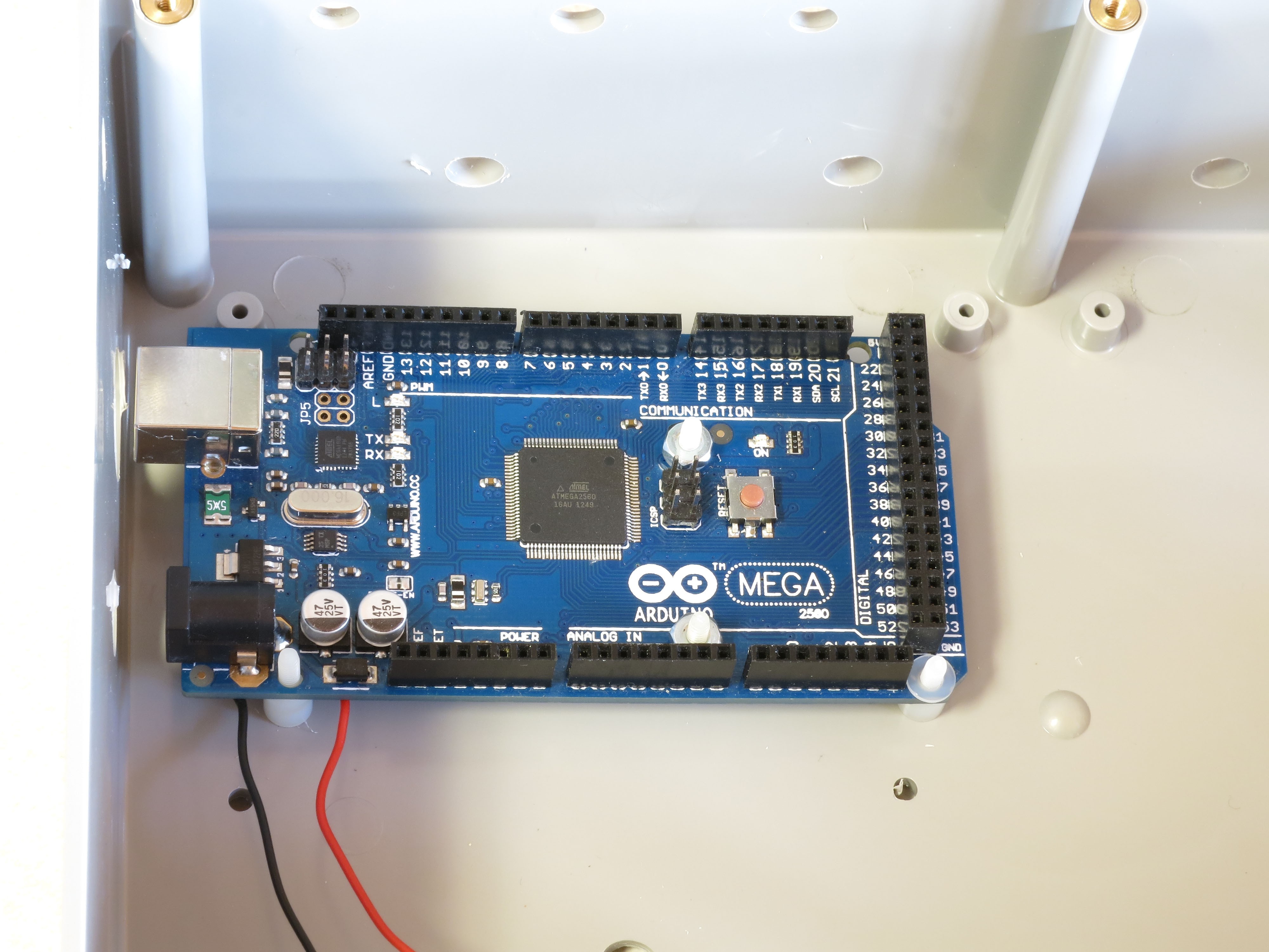
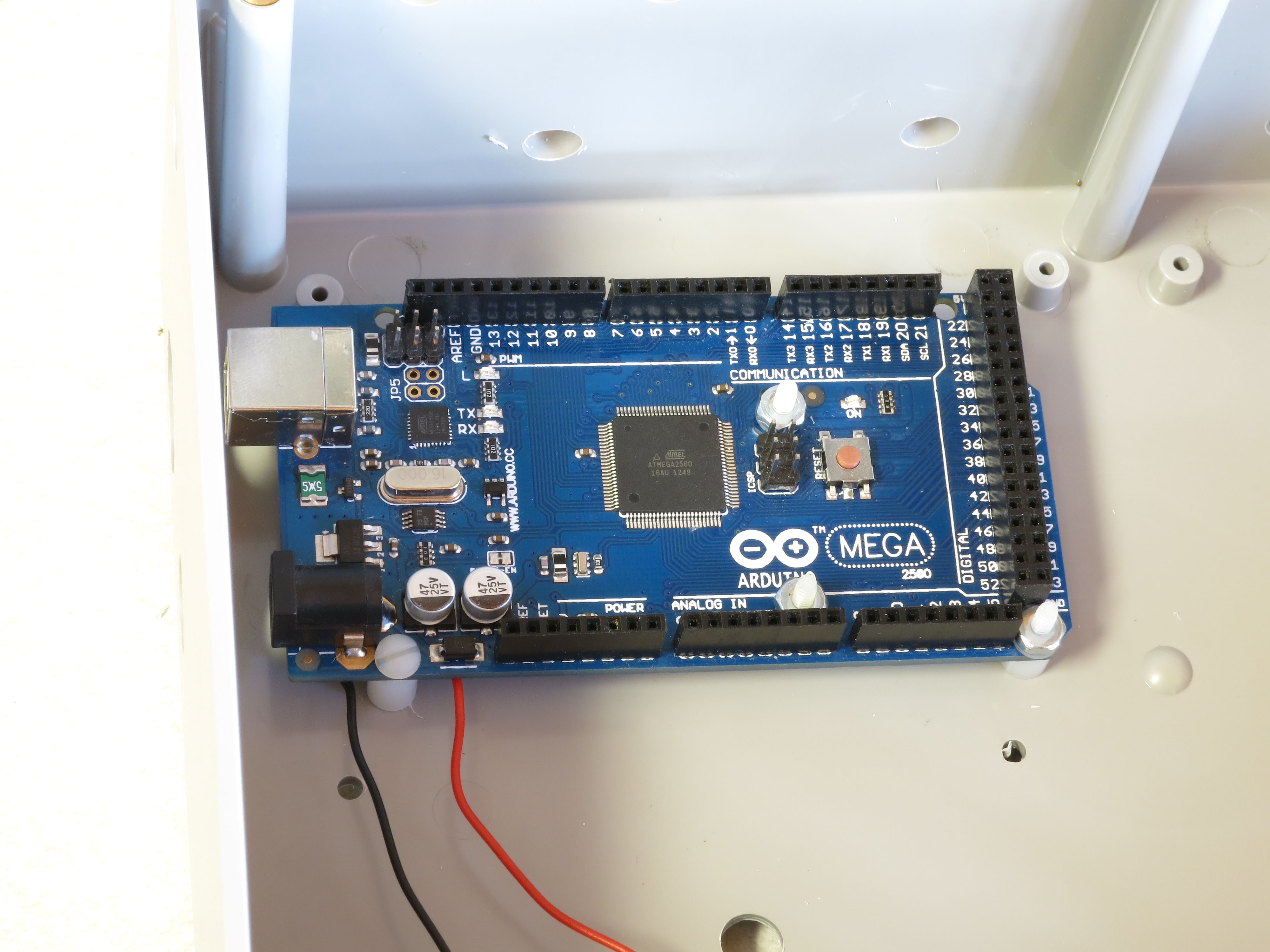
Place the Arduino on top of the screws so that they go through the holes in the Arduino. Put a washer and nut (preferably nylon) on the center 2 screws, and tighten the nuts to hold the Arduino in place:
![]()
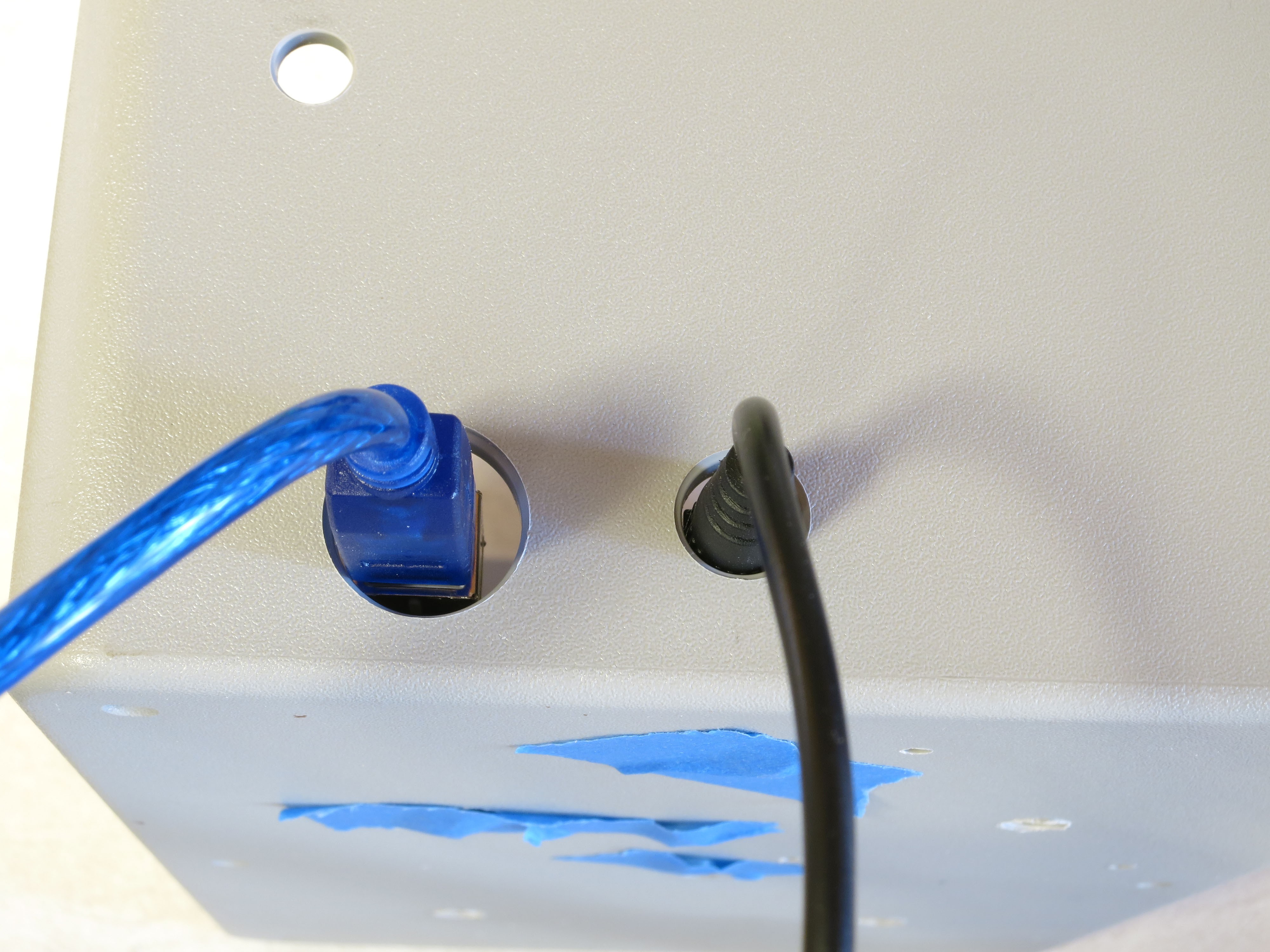
Check to make sure you can plug both a USB cable and the power cable into the Arduino through the holes drilled in the left panel:
![]()
You can see the tape holding the screws in place below. If they don’t fit, take the Arduino out and drill the holes larger until they do fit (which I have done on every previous control box I’ve built; this is the first one where they fit on the first try).
If everything fits, attach nuts to the other two screws. First, the screw on the right - there’s just barely enough room for the nut to fit the two adjacent headers, but not enough to actually turn the nut in place. So you’ll have to turn the screw from the backside to fully tighten it. The screw on the left is even worse – there’s no room for a nut there at all. So you’ll need to carefully pull it out, leaving the spacer in position, then insert it the opposite way and attach washer/nut on the outside.
![]()
Install the power strip board with one 4-40 metal screw in the PCB standoff in the lower left-hand corner, and 3 4-40 ¾” screws through the holes, with spacers. As with the Arduino screws, you’ll need to tape them at the bottom of the enclosure to hold them in place:
![]()
Looks like the Arduino board is slightly askew. No worries, as long as you can plug in the USB cable and power cable, it’s OK.
Insert the MOSFET driver shield into the Arduino, taking care to make sure the right pins go in the right holes. Apply pressure evenly when inserting, otherwise you can bend some of the pins during insertion. Make sure the shield is fully inserted into the Arduino.
Plug the CAT4101 board into the MOSFET shield:
![]()
Holding the CAT4101 board horizontally, take a drill bit and use it to mark drill hole positions through the two holes on the right side of the PCB. Remove the board, then drill two holes for #6 screws at those marks. Insert two 1” #6 screws, taping them to the bottom of the enclosure to hold them in place. Place a ½” spacer and a 1/8” spacer/thick washer on both screws:
![]()
Reinsert the CAT4101 board into the MOSFET shield, inserting the ends of the screws into the holes at the end of the board. Check that the board is close to horizontal; if not, you may need to add/subtract spacers of various thicknesses to make it so. Fasten the board to the screws with washers/nuts.
![]()
Now is a good time to attach heat sinks. I’m not actually 100% sure you need them on the CAT4101s, and I’m pretty sure you don’t need them on the MOSFETs. The former may get a bit warm, but theywill work fine up to 150C at which point they shut down automatically. Since each CAT4101 will only be on for a few seconds total during an RTI session, it’s unlikely it will get anywhere near that hot. The MOSFETs have even less of a thermal problem – an Rds of around .15 plus a max current of 1 A means they’ll have to dissipate about 0.15W of heat max for a few seconds, which shouldn’t be an issue.
Me being paranoid, I installed heat sinks on both the CAT4101s (right) and the MOSFETs (left):
![]()
In retrospect, the MOSFET heat sinks were a bad idea. They came close to blocking a couple of key connectors on the MOSFET shield. So I’ve made an executive decision, determined that you don’t need heat sinks on the MOSFETs, and cut the heat sink count on the component list from 16 to 8. Still not convinced you’ll need them on the CAT4101s, but there’s a better case for them there; with a 12V power input, they may need to handle a few watts of heat for a few seconds.
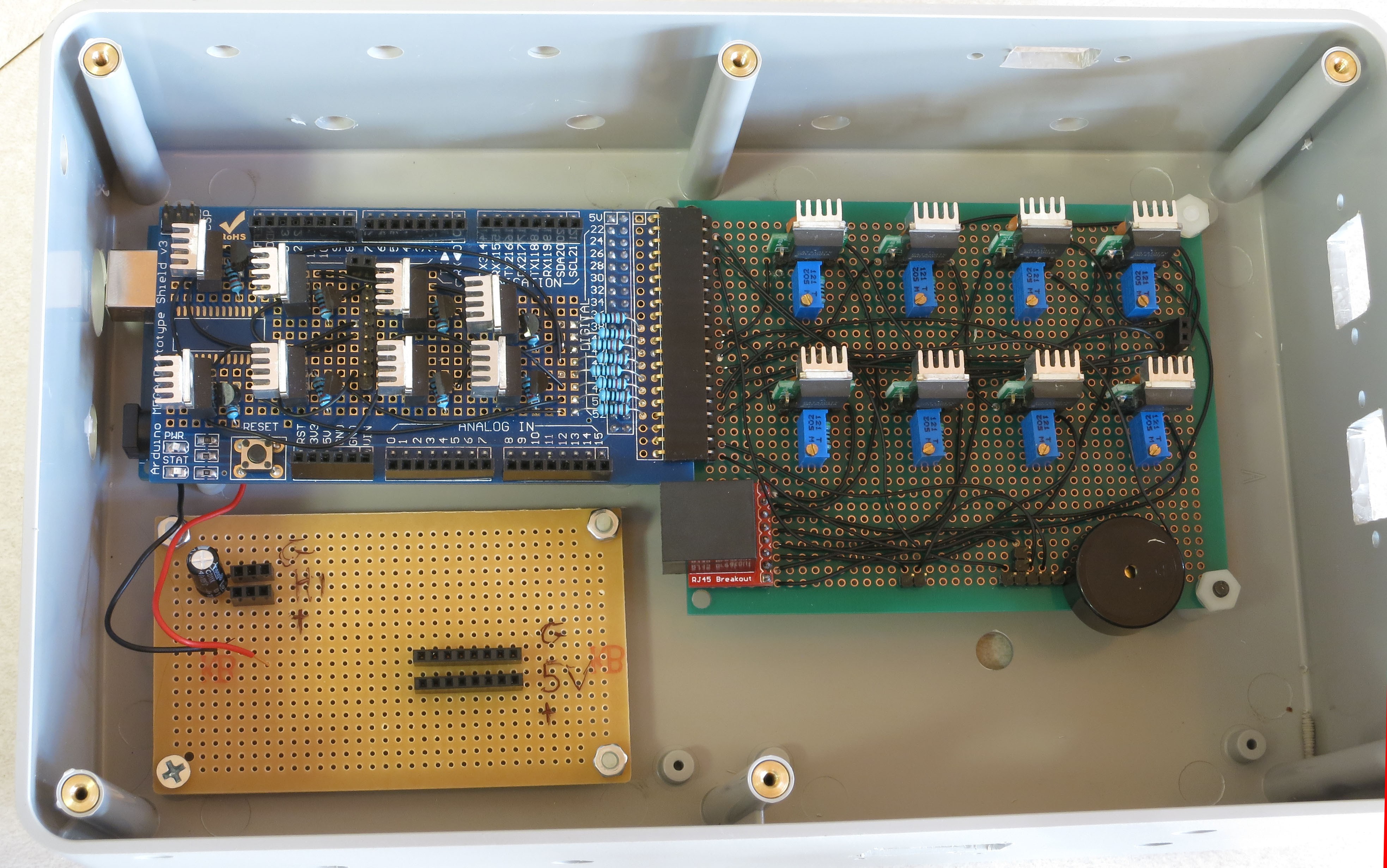
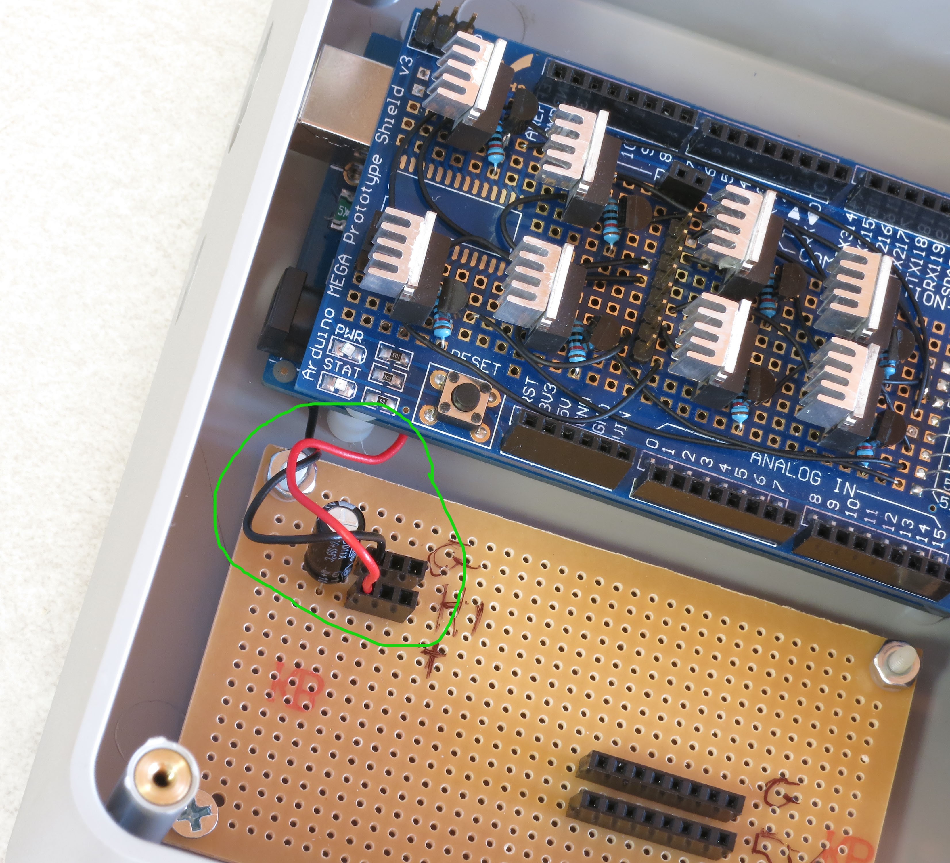
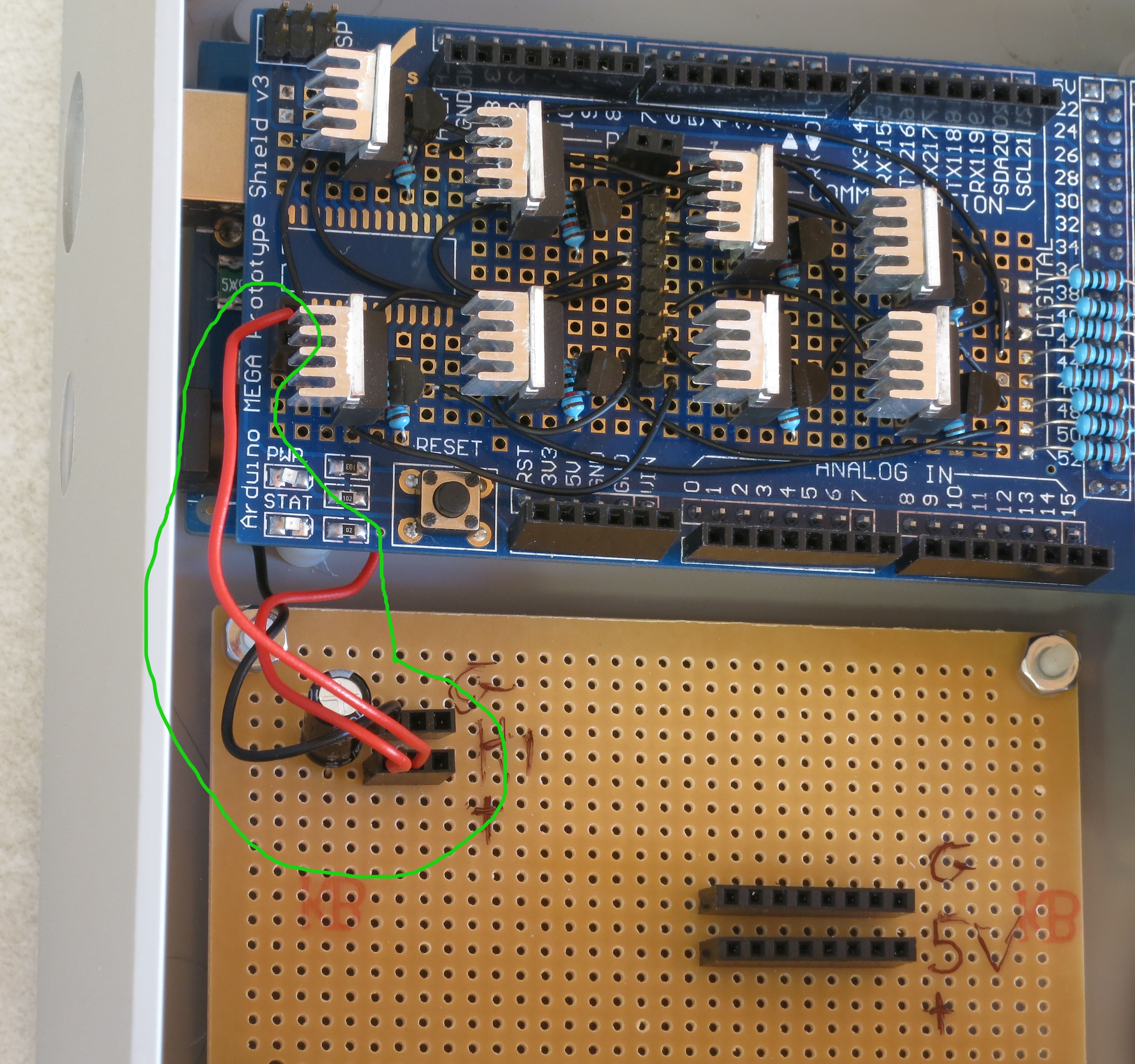
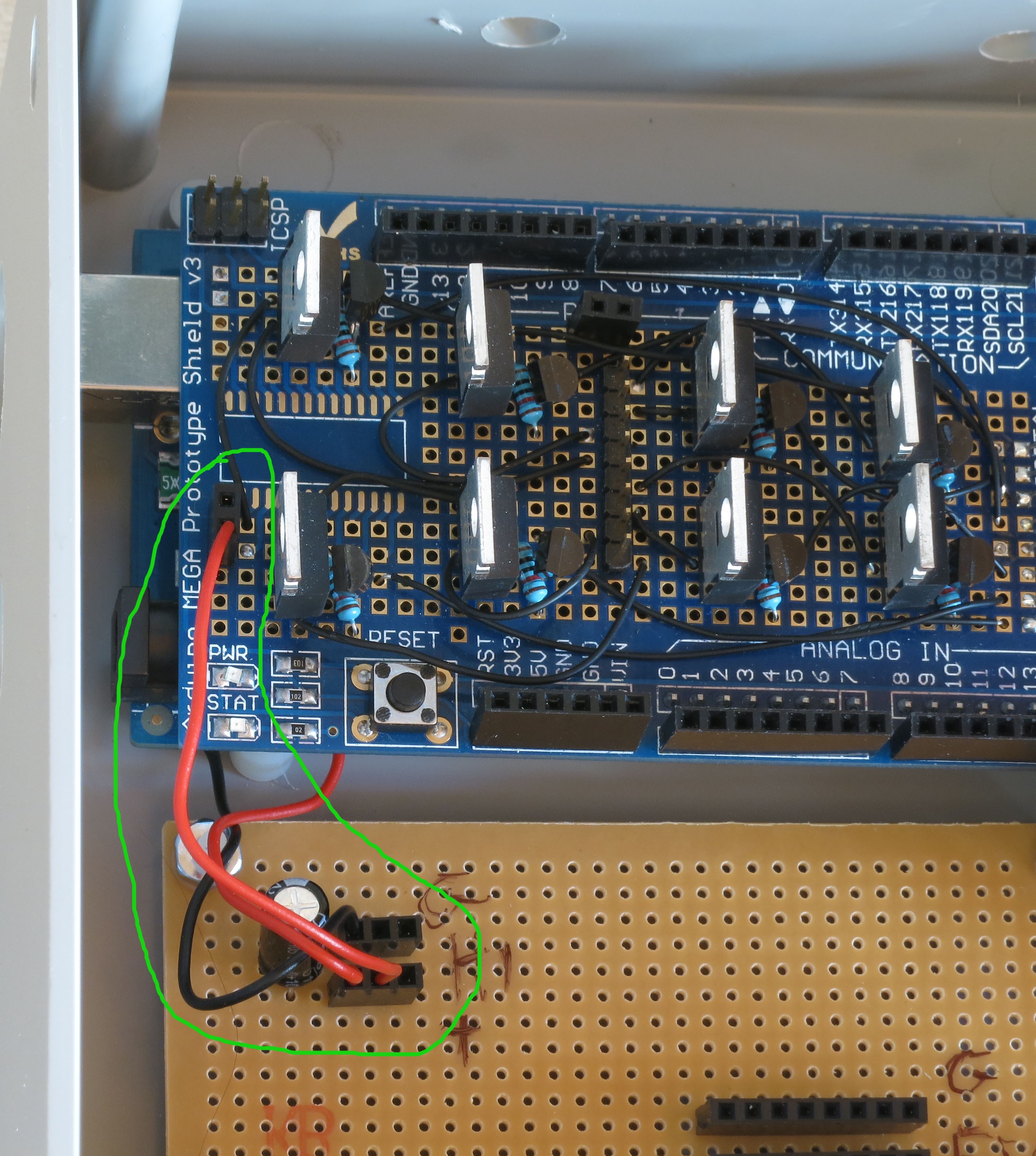
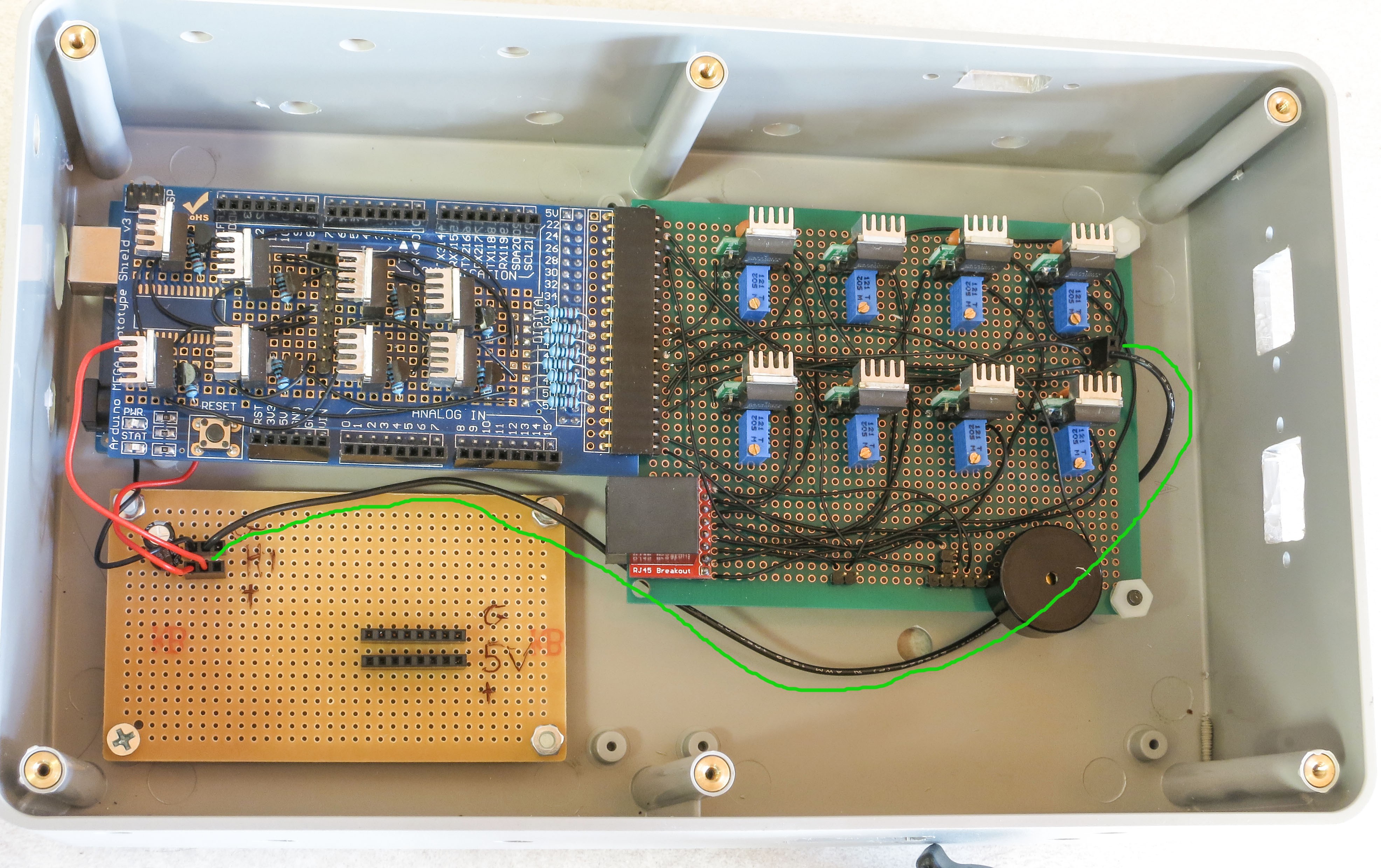
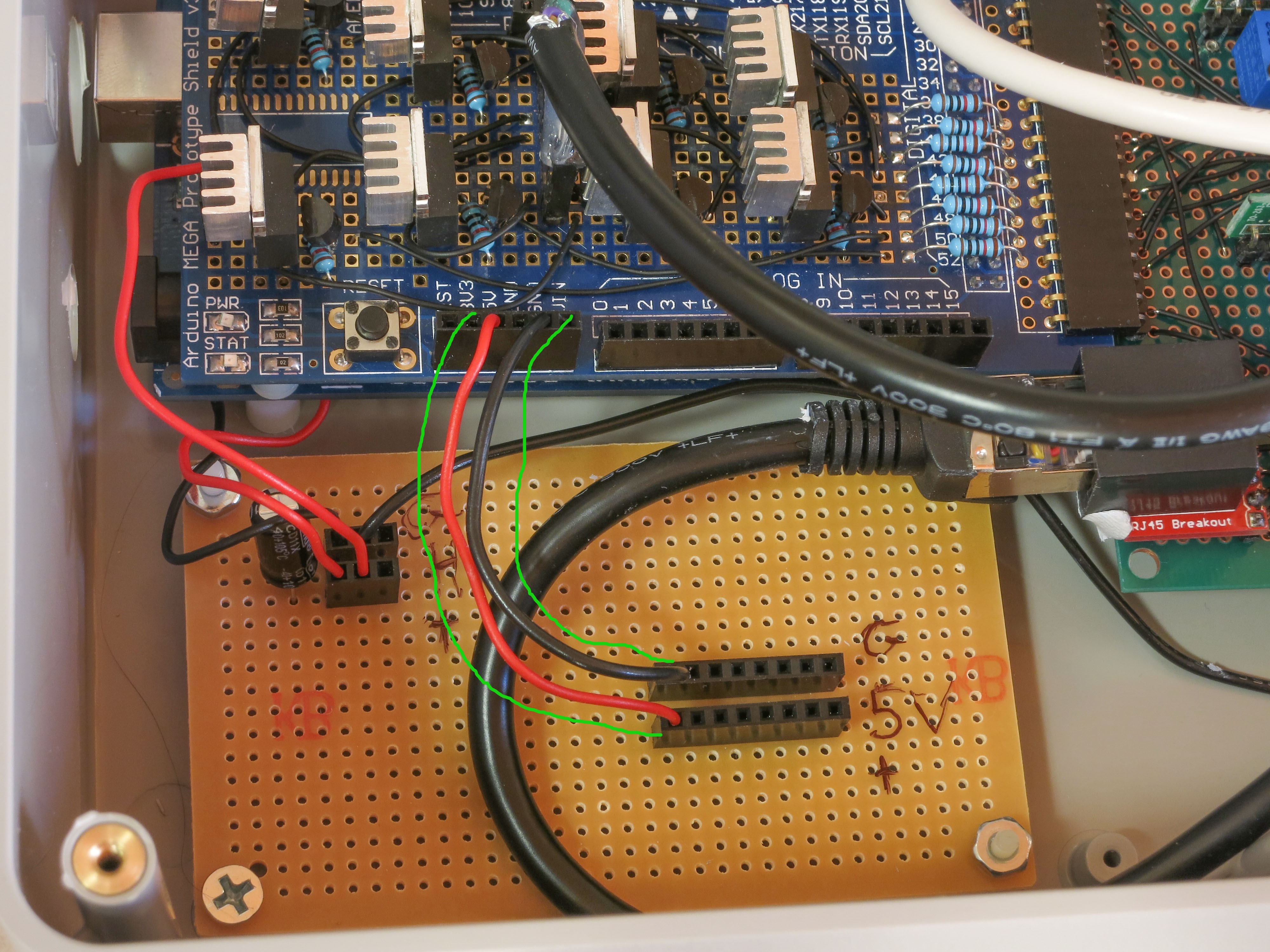
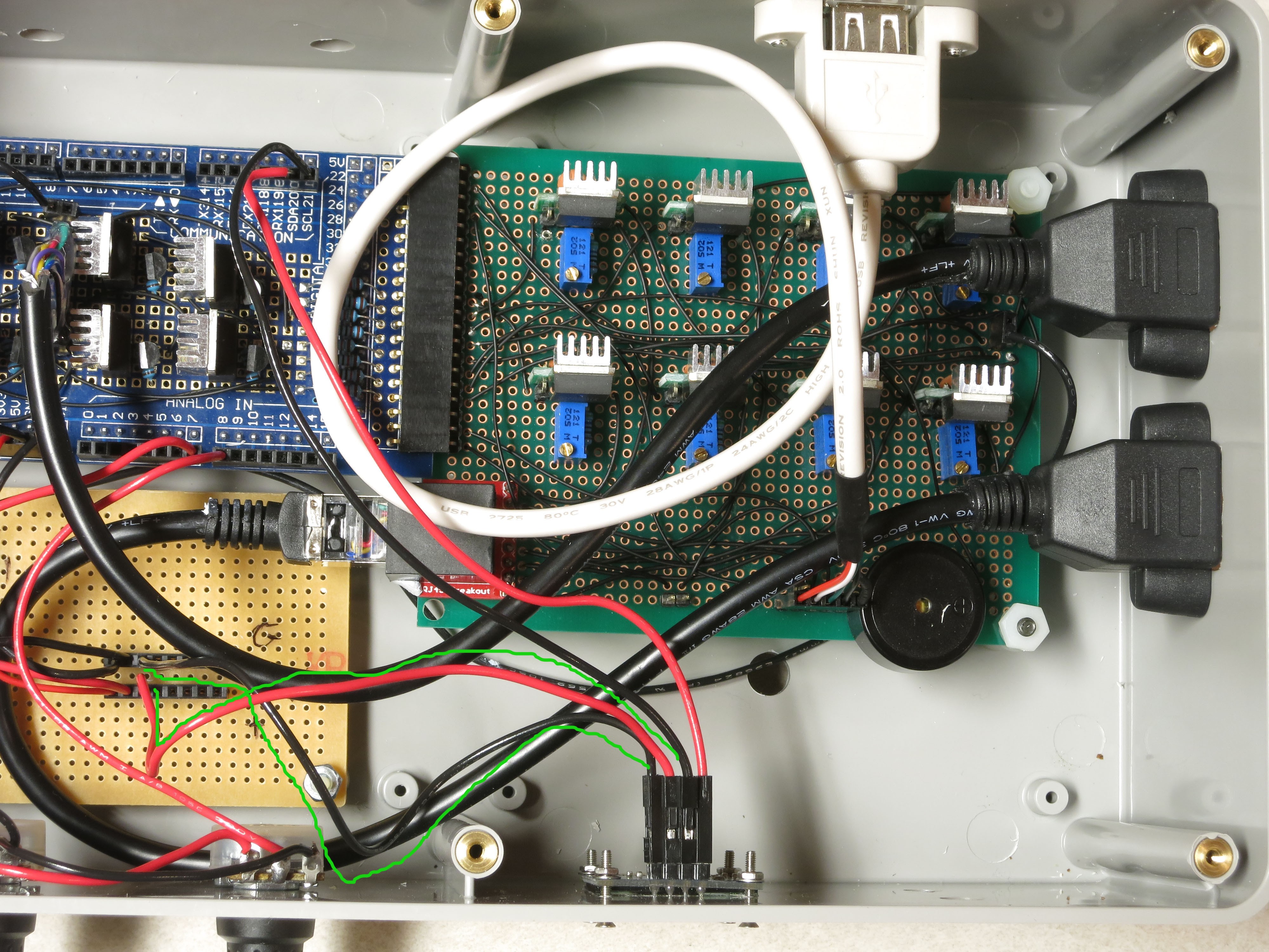
Insert the black and red power wires from the Arduino as shown (circled in green), red (+ voltage) to the bottom strip, black (ground) to the top. You might also want to label the power connectors as shown; upper left is high voltage directly from the power supply, while lower right will get 5V of power and ground directly from the Arduino.
![]()
Connect a red jumper wire from the +V header at upper left to the header on the MOSFET driver shield; this will be the main current supply to the LEDs:
![]()
The heat sink blocks a good view of that shield header, but I shot a similar picture before installing the heat sinks:
![]()
Now run a long black jumper wire from the high voltage ground strip to the double header on the CAT4101 board; this will be the main ground for the LEDs. Try running it underneath the CAT4101 board as shown, to keep it out of the way:
![]()
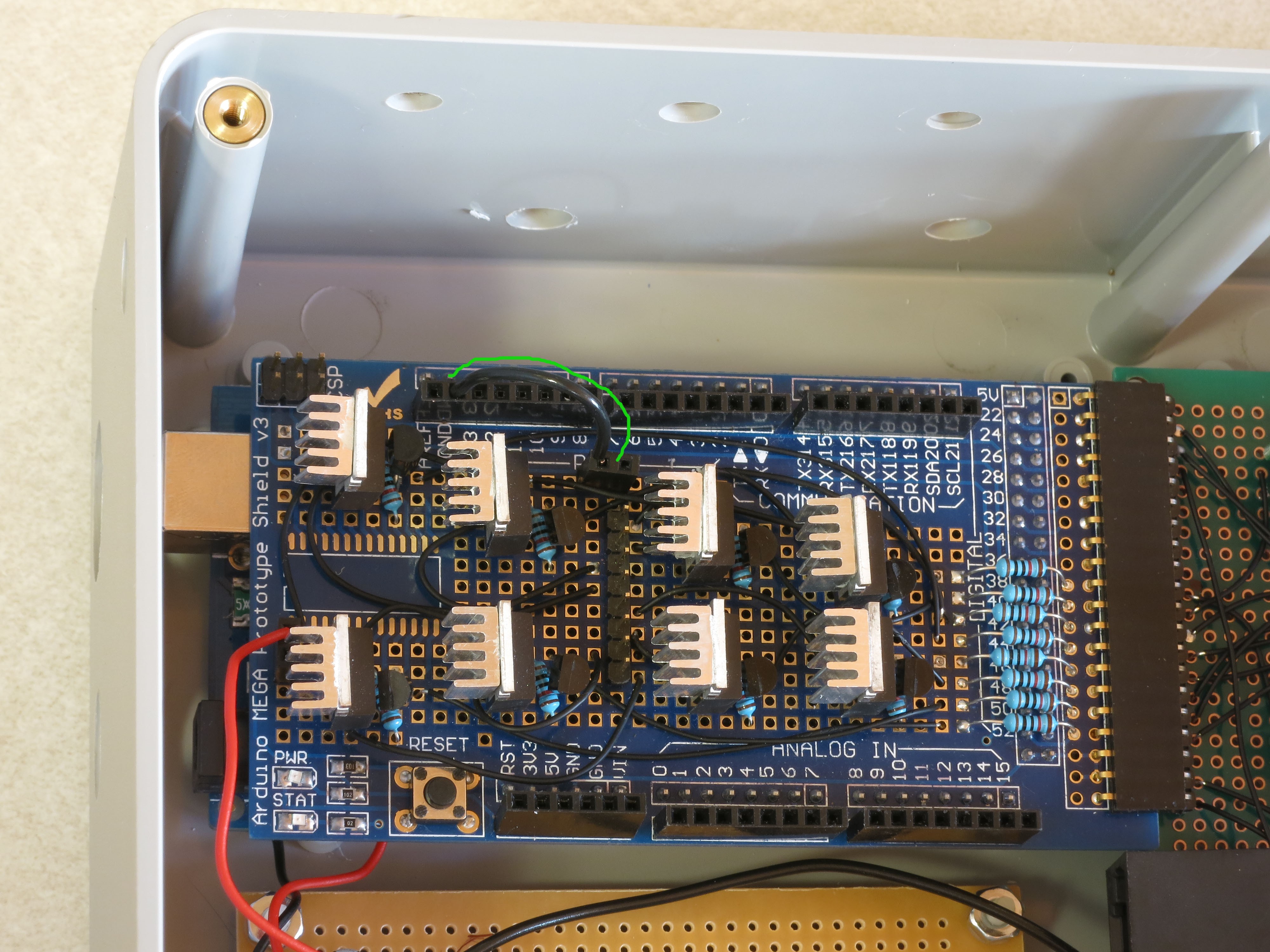
Run a short black wire jumper from the Arduino ground header (upper left on the Arduino board) to the double header nearby on the MOSFET driver shield:
![]()
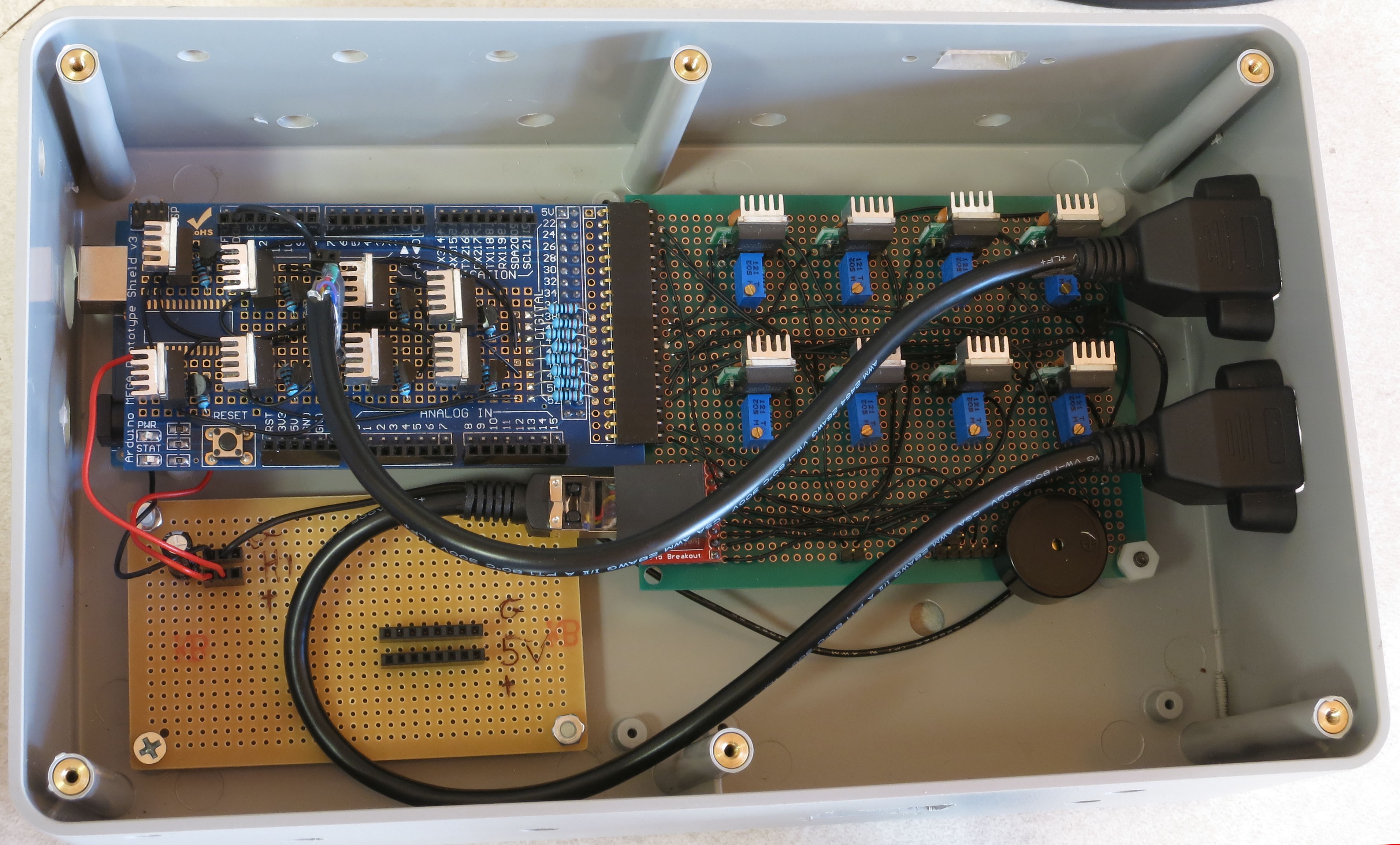
Install the two Ethernet panel jack cables as shown. Make sure you have the connector to the MOSFET board oriented properly, with pin 1 at the top. Put the MOSFET-connected panel jack on the rear side of the right panel, as that’s where the red +V cable from the RTI dome will attach (mnemonic: “red to the rear”).
![]()
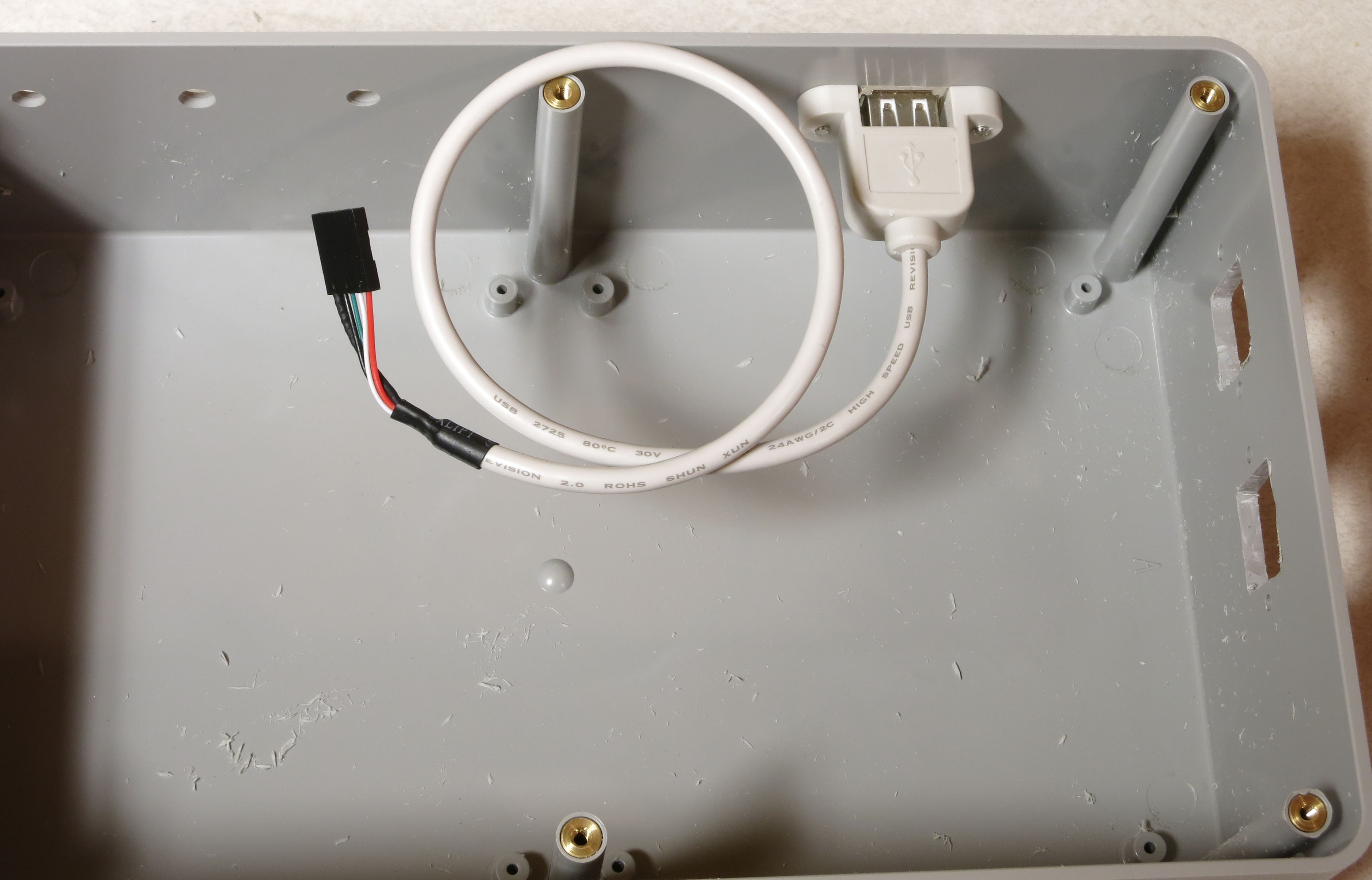
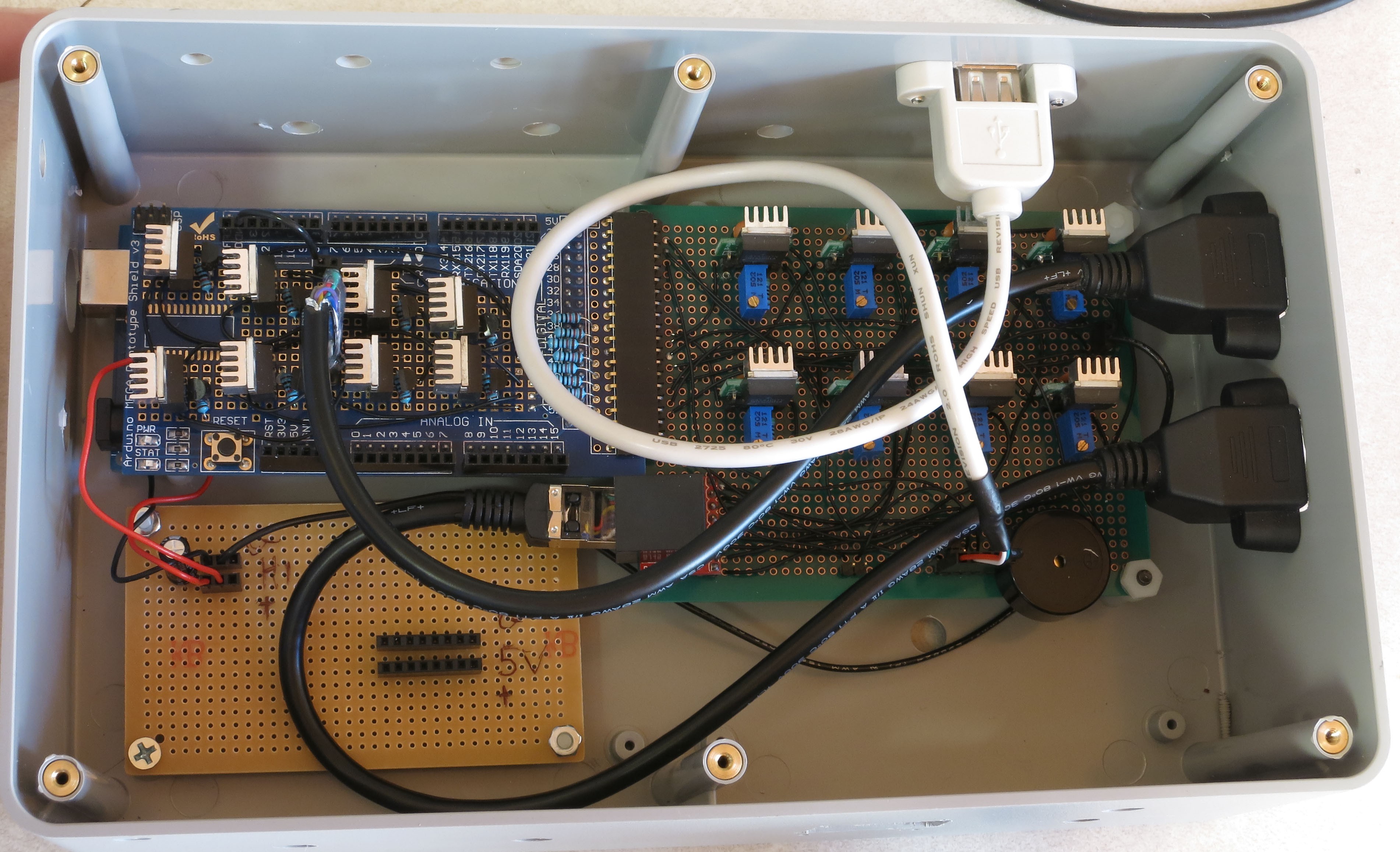
Install the USB panel jack connector. The black wires on the 5-pin header should plug into the right side of the 5-pin connector on the CAT4101 board. Install the panel jack with the USB symbol showing on top, so that USB cables will plug in correctly when their USB symbol is on top.
![]()
The USB jack on the back should look like this if the panel jack is correctly installed:
![]()
Run a red jumper wire from the 5V Arduino header to the + voltage strip on the lower right of the power board; run a black jumper from the nearby ground header to the adjacent ground strip:
![]()
From this point on, the controller box is capable of running the “Dazzler/Serial Test” programs (described at the end of the LED dome wiring instructions) that will light up the wired LEDs in the RTI d
-
28Step 28
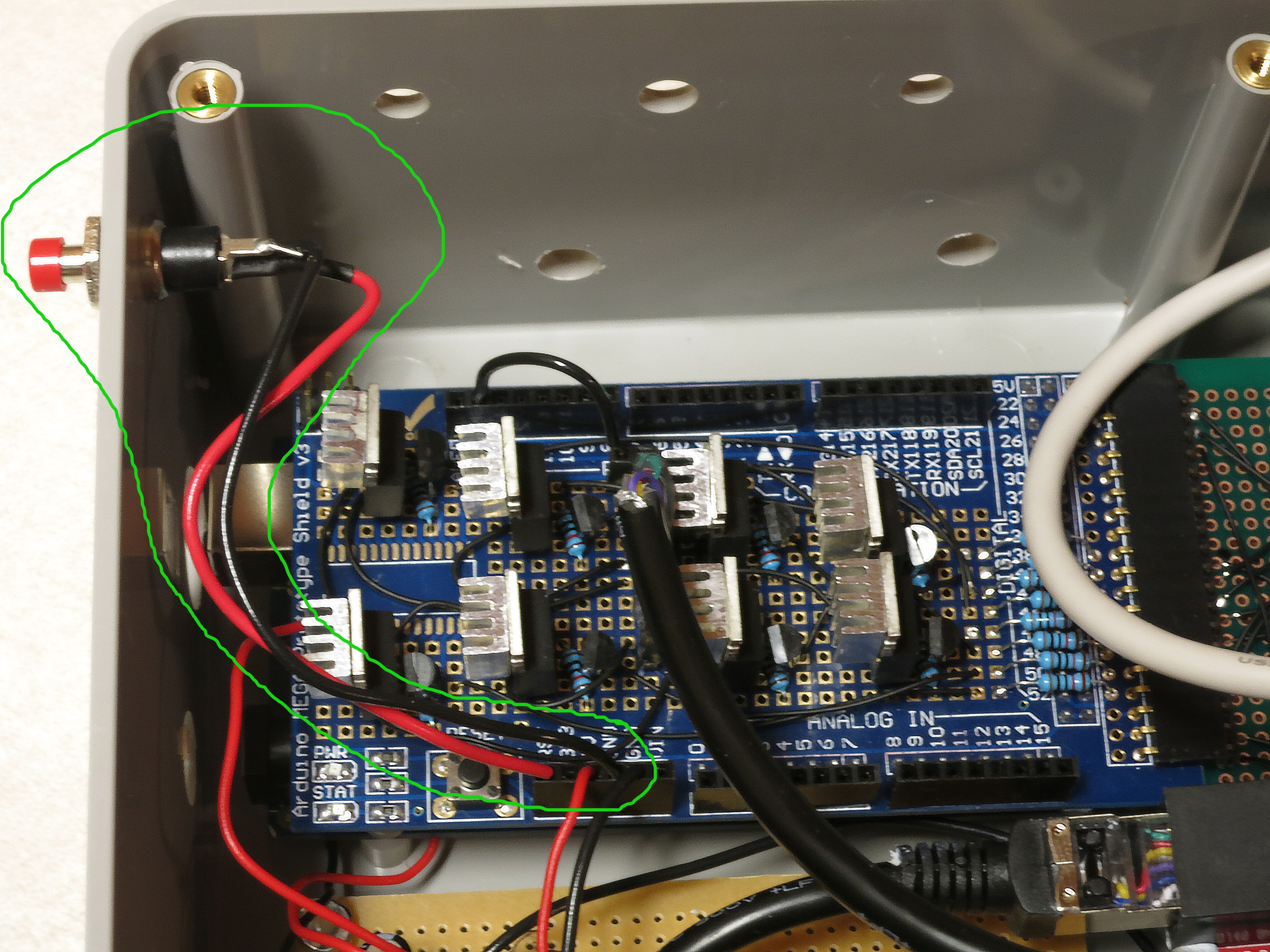
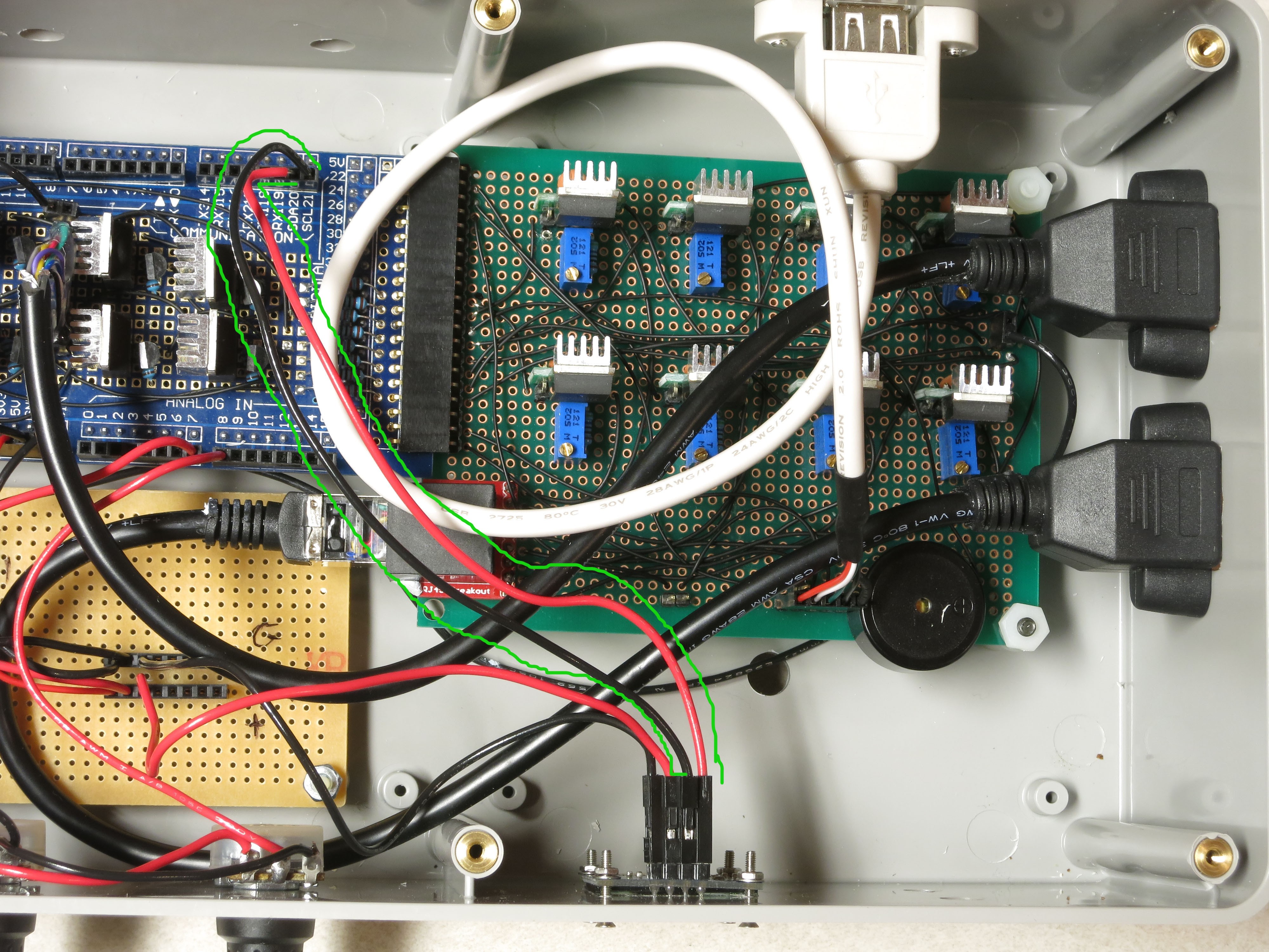
Next, the reset switch. Grab one of the two red pushbutton switches, solder wires to both terminals, put on heat shrink insulation over the exposed leads if necessary, then install it in the small hole in the upper left corner of the left side. Connect the wires to the Reset and GND headers in the lower left Arduino header row, as shown circled in green in the picture below (doesn’t matter which wire is which for this connection):
![]()
Apologies for the lack of pictures on this step, but hopefully it’s simple enough to understand from just the one picture.
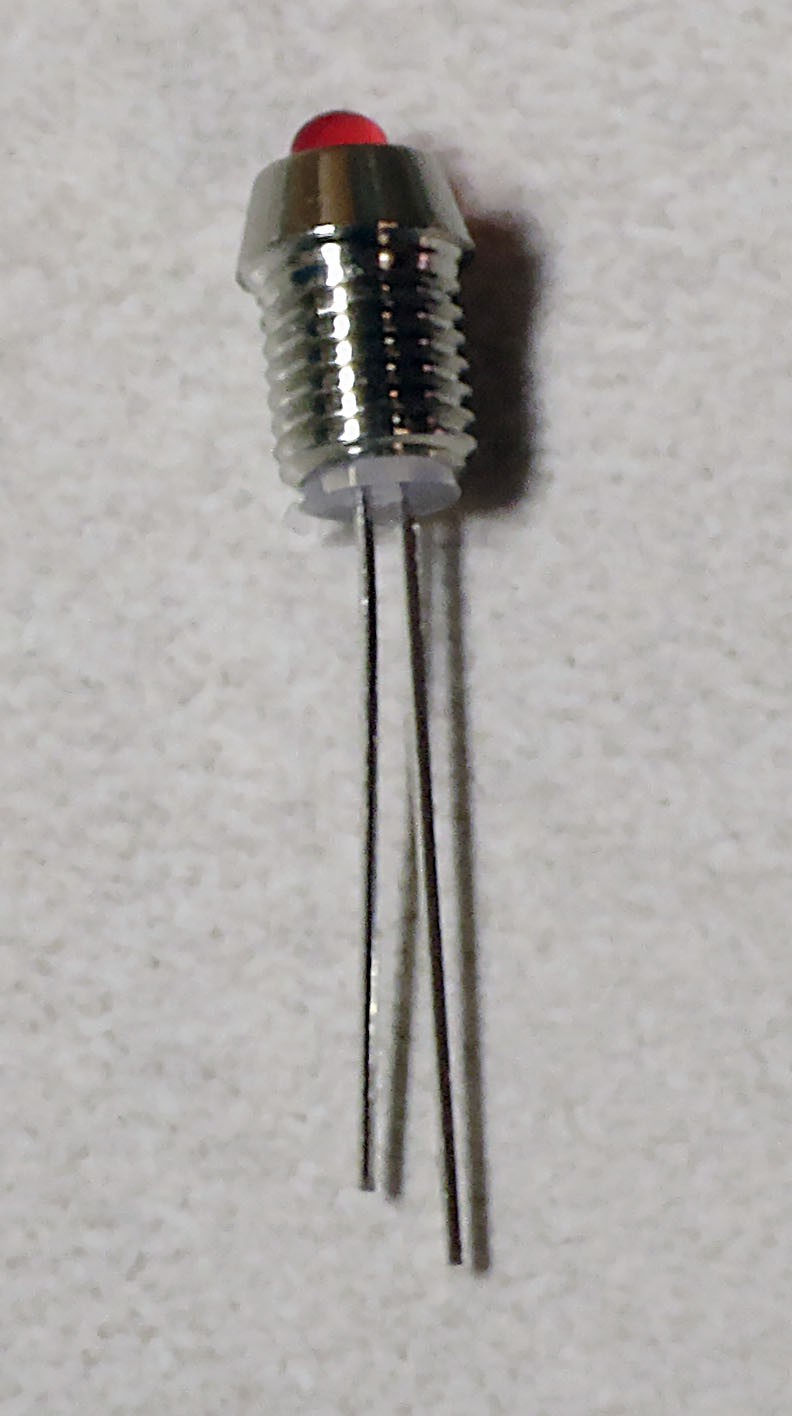
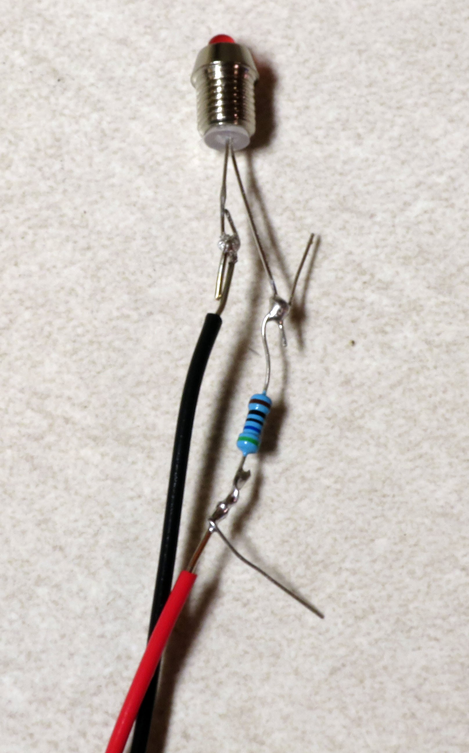
Take a 3mm red LED, and insert it into the 3mm LED holder. There should be a little plastic insert inside the LED holder with two small holes – make sure the LED leads go through the two small holes separately, which keeps them from shorting out.
![]()
Solder a 560R resistor to the longer LED lead (the anode), then solder a red wire to the other end of the resistor, and a black wire to the shorter LED lead (the cathode):
![]()
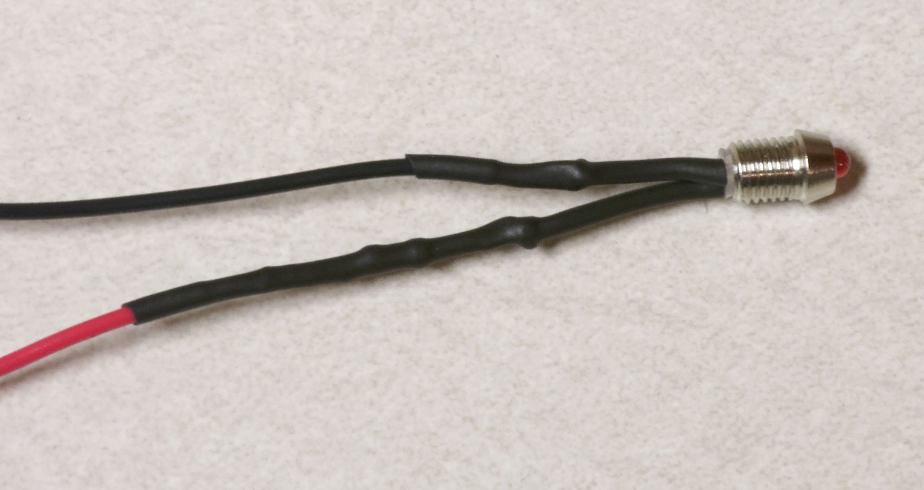
Trim the excess leads off, and cover the exposed wires with heat shrink tubing to prevent shorting:
![]()
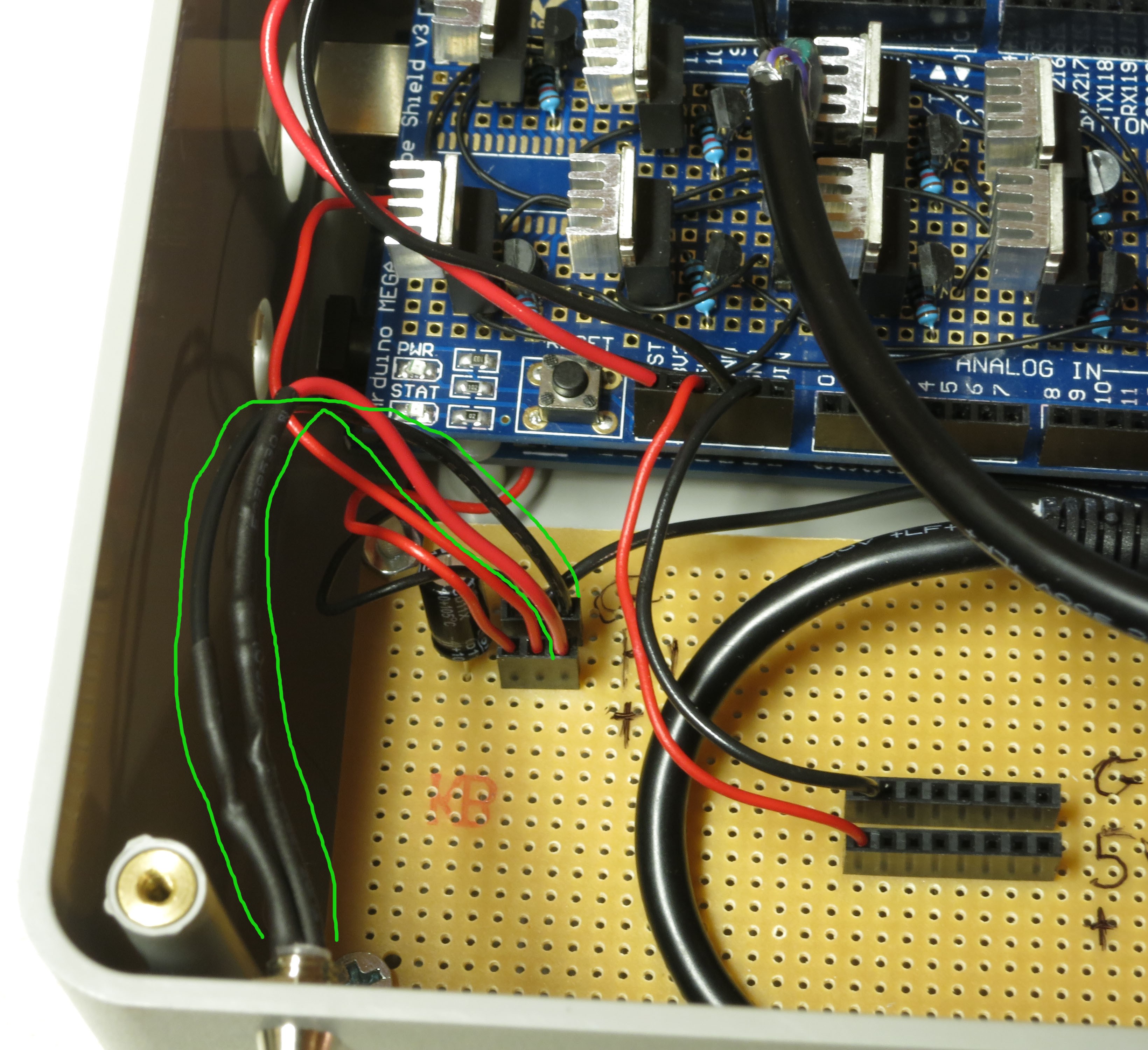
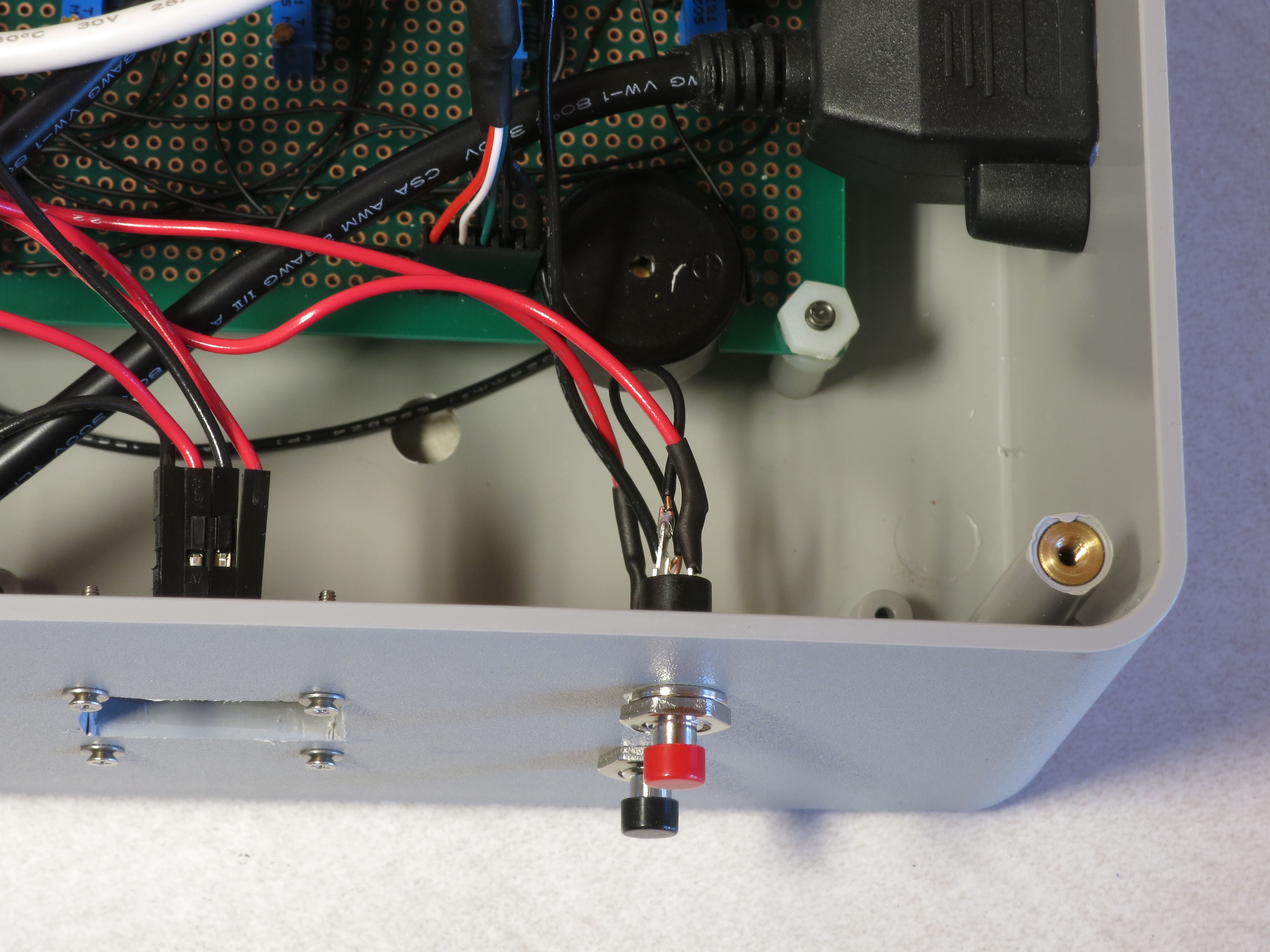
Run the two LED leads through the hole in the upper left front panel you drilled earlier; run the nut over the two wires from the inside and secure the LED holder in place. Plug the red wire into the + voltage strip for high voltage, plug the black wire into the ground strip:
![]()
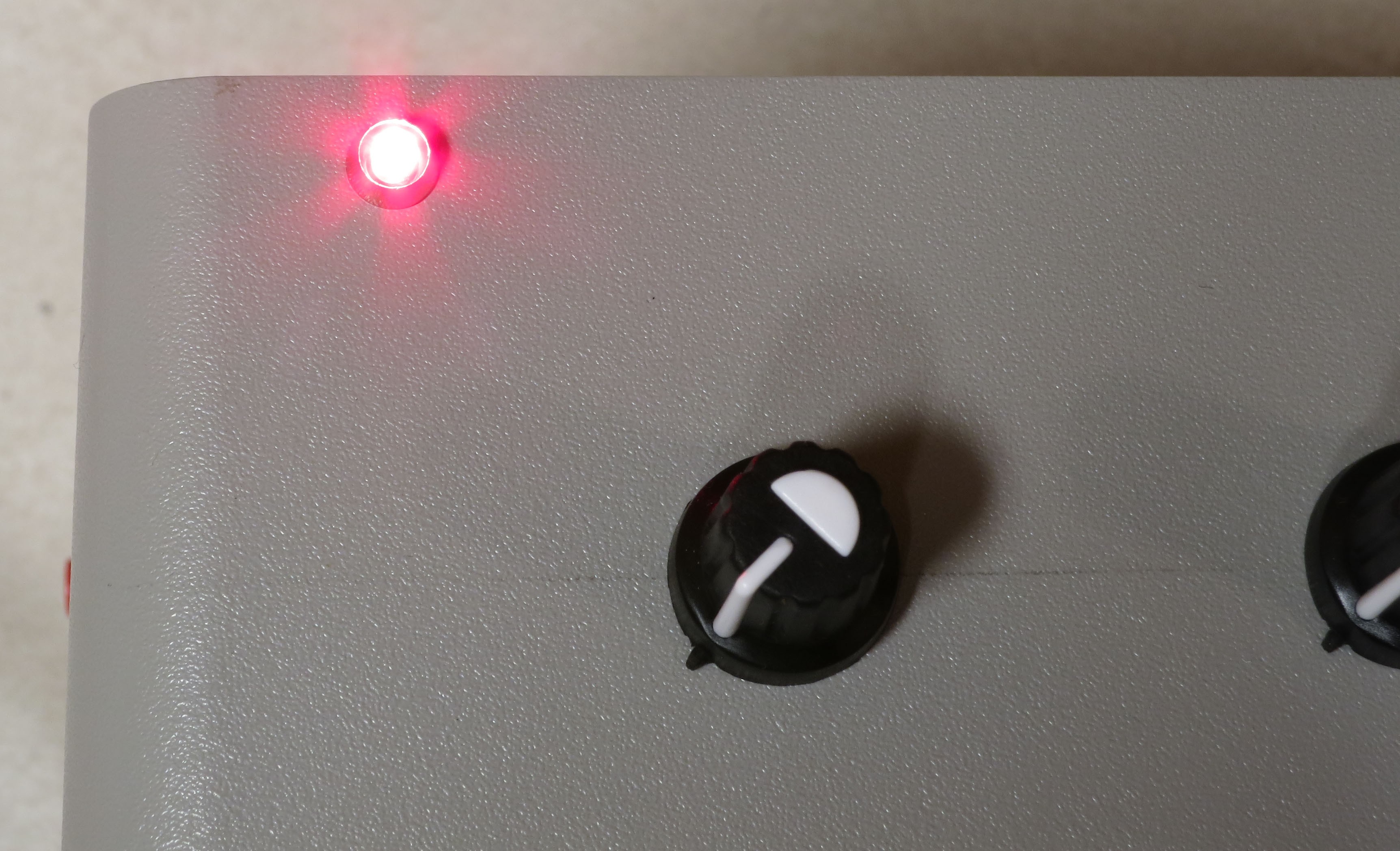
If you want to check the LED light, just plug in the power supply to the power jack on the left. The light will only go on if this main power supply is plugged in; if you only plug in the USB cable on the left, the Arduino will start up, but no power will go to either the power LED or the LEDs in the dome. The resistor value was chosen so that the LED would work with any voltage from 9 to 12 V DC (without blowing out).
![]()
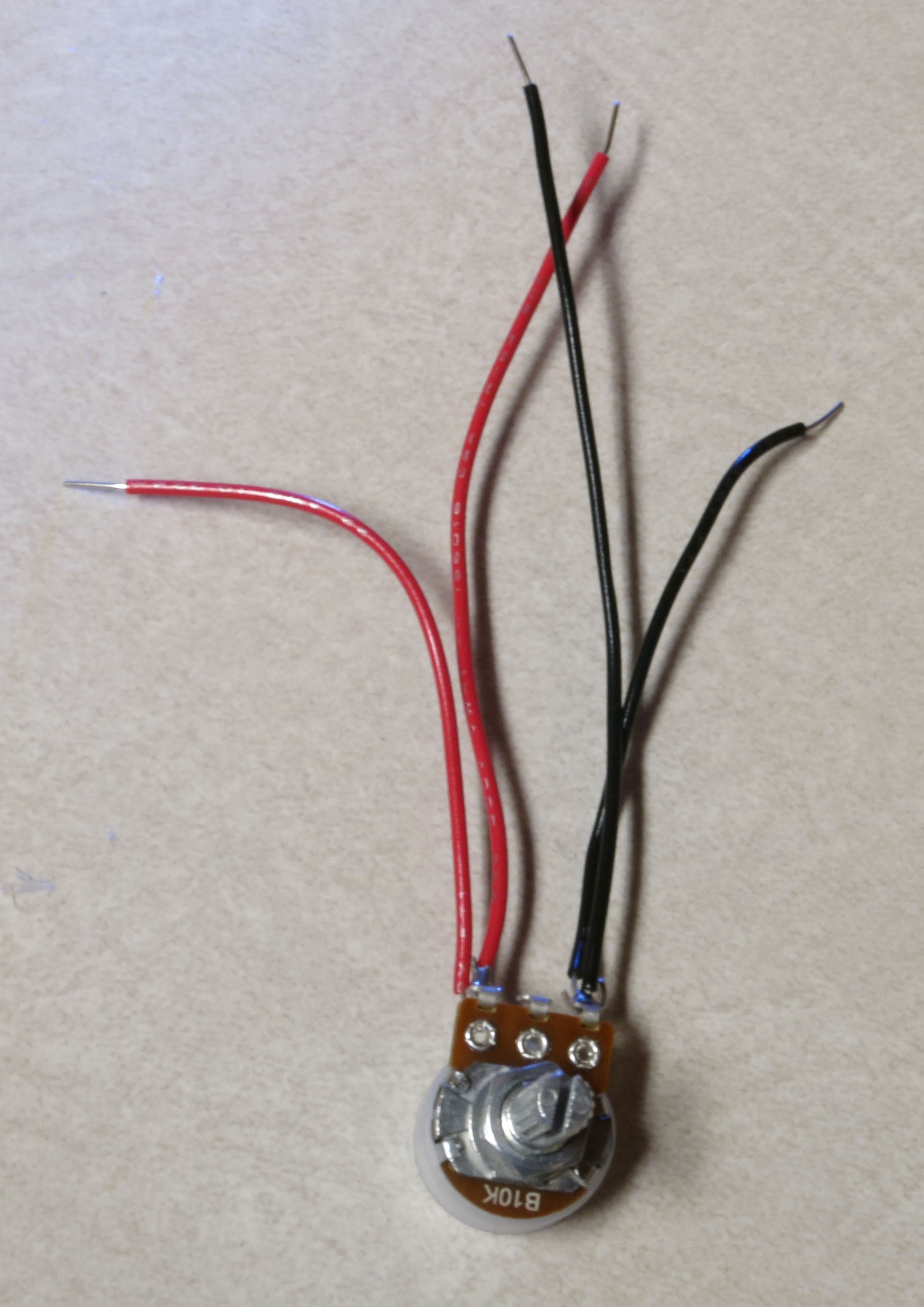
Time to wire up the two 10K potentiometers. Solder wires to the first one as shown in the picture below (colors matter here):
![]()
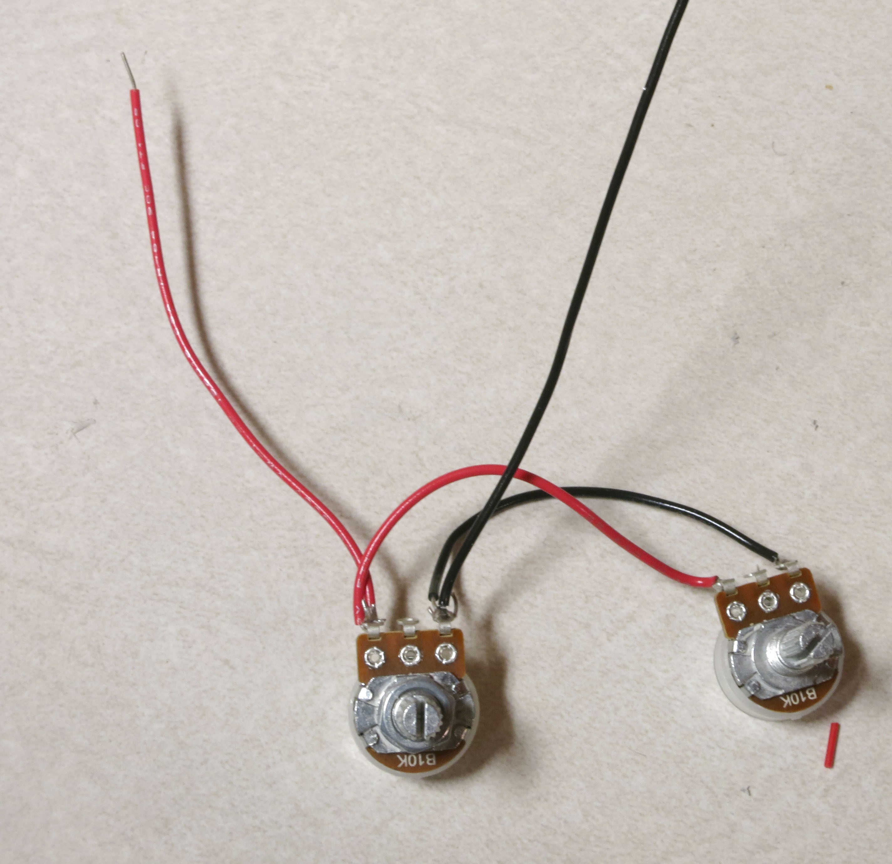
Then solder the short red and black wires to corresponding terminals on the other 10K pot:
![]()
The idea here is that you’ll be applying a common 5 volts across both sets of corresponding terminals, so you’ll only need to plug one set of wires into voltage/ground terminals.
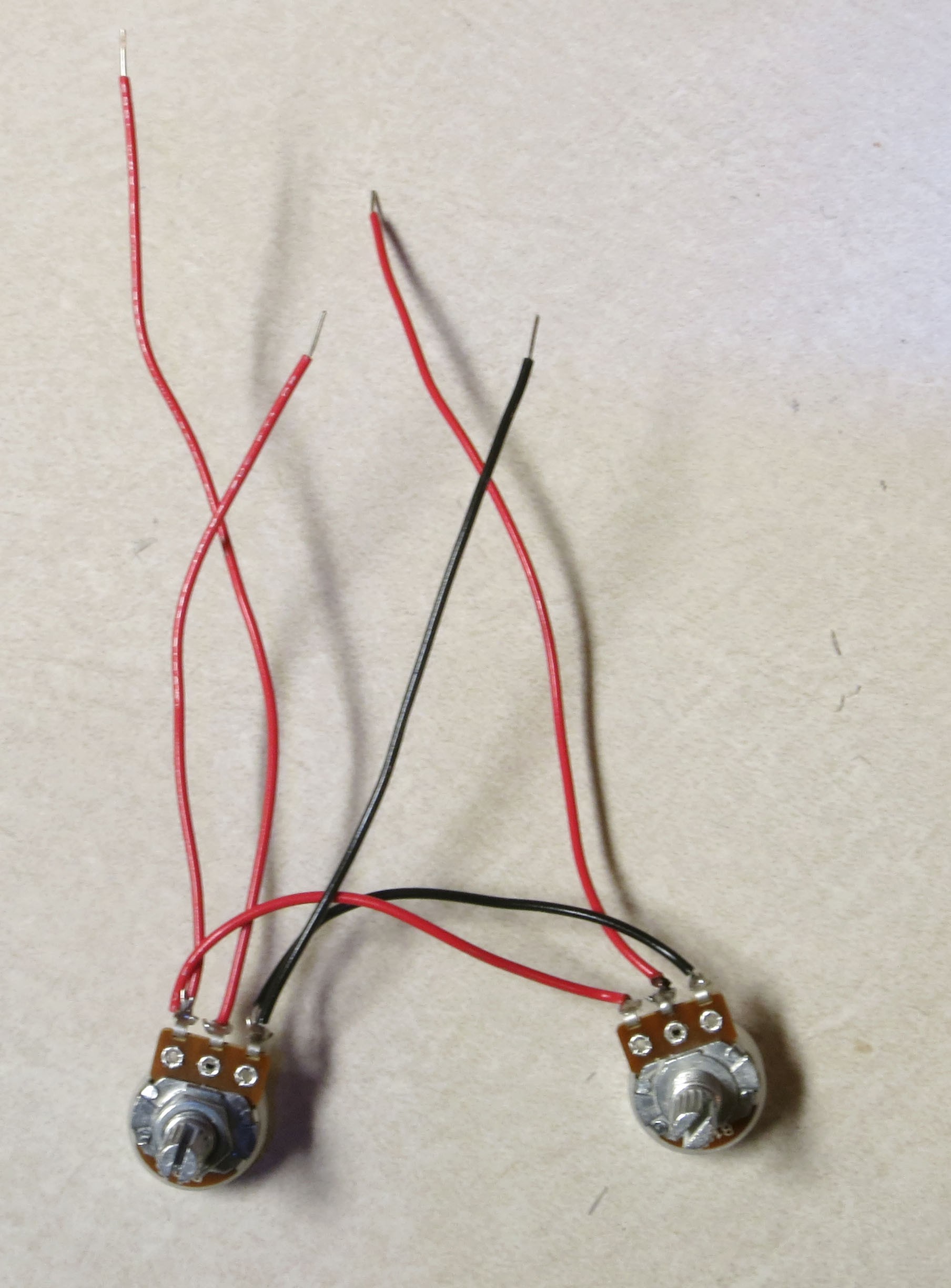
Now solder longer red wires to the center terminals of both potentiometers:
![]()
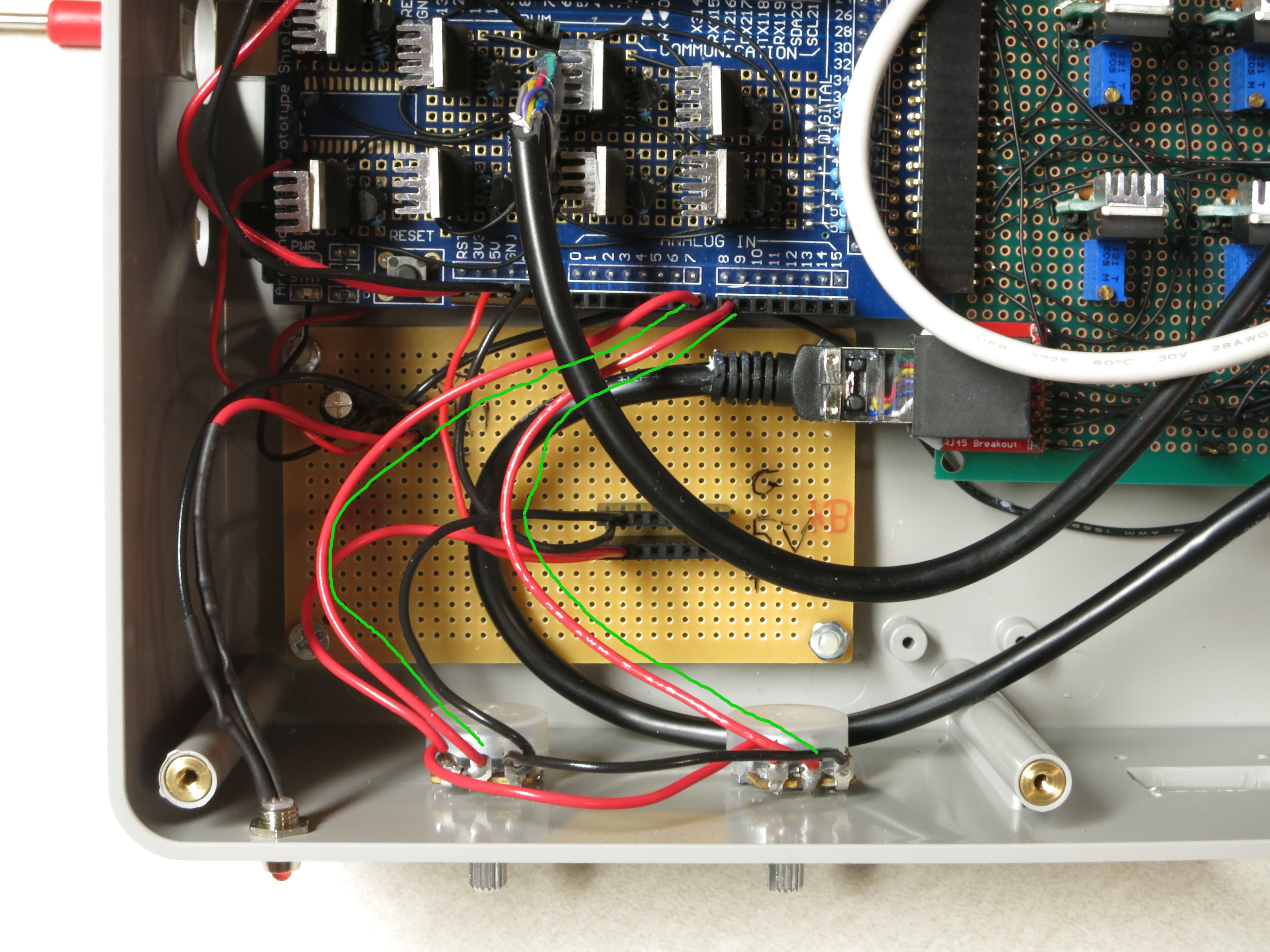
Install the two potentiometers into the left two holes of the control box. Plug the red and black outside terminal wires on the left potentiometer into the ground and 5V strips on the lower right of the power board.
![]()
Plug the long red wire from the left pot into Analog In 7, from the right pot to Analog In 8.
![]()
You can put knobs on the pots now:
![]()
If you’re installing the OLED display, re-attach the four connector wires you made earlier as before: black to GND, red to VCC, black to SCL, red to SDA. Feed the wires through the cutout in the front panel for the OLED, and attach the OLED display using screws and nuts. Connect the red VCC wire and the black GND wire to the +5V and ground strips on the lower right of the power board, respectively:
![]()
Connect the SDA and SCL wires to the matching Arduino headers on the top right of the board:
![]()
If you want, you can check the installation now with the RTIMage_OLED_Tester program discussed in the previous OLED test section.
Grab a red and black pushbutton switch, and wire them as below:
![]()
The install them in the two right holes in the front panel, red button on top:
![]()
Run the black wire to the ground header on the lower right of the power strip:
![]()
Run the red wire from the red button to ANALOG IN 13, from the black button to ANALOG IN 12.
![]()
“Huh? Analog?”, you might ask if you’ve worked with Arduino before; switches are normally connected to digital inputs. You can define any of the analog pins as digital inputs, and I do that in the software that runs the control box. Just trying to keep the wiring a bit neater.
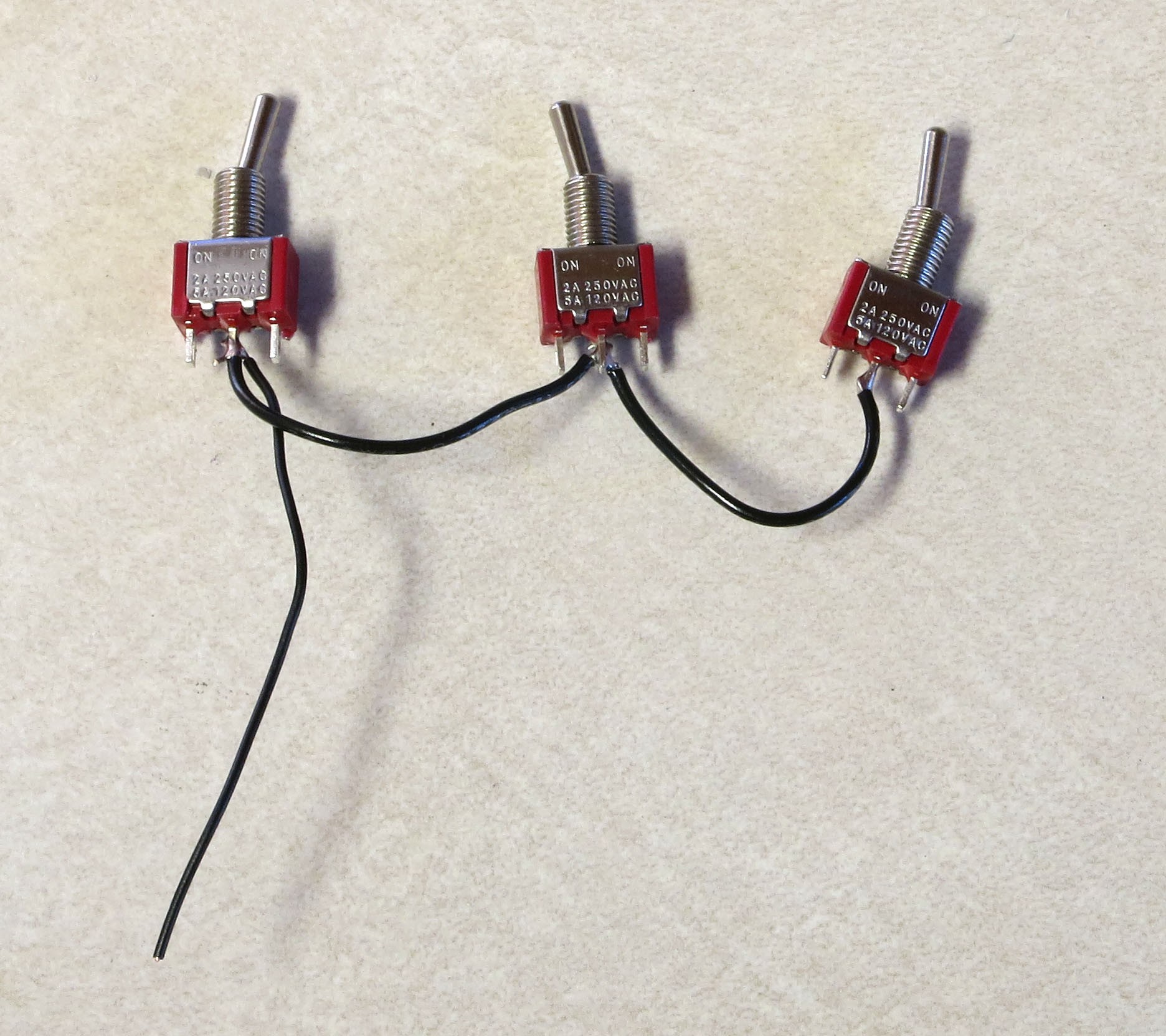
Grab the three toggle switches, and solder up the central terminals with black wire; these will connect to ground:
![]()
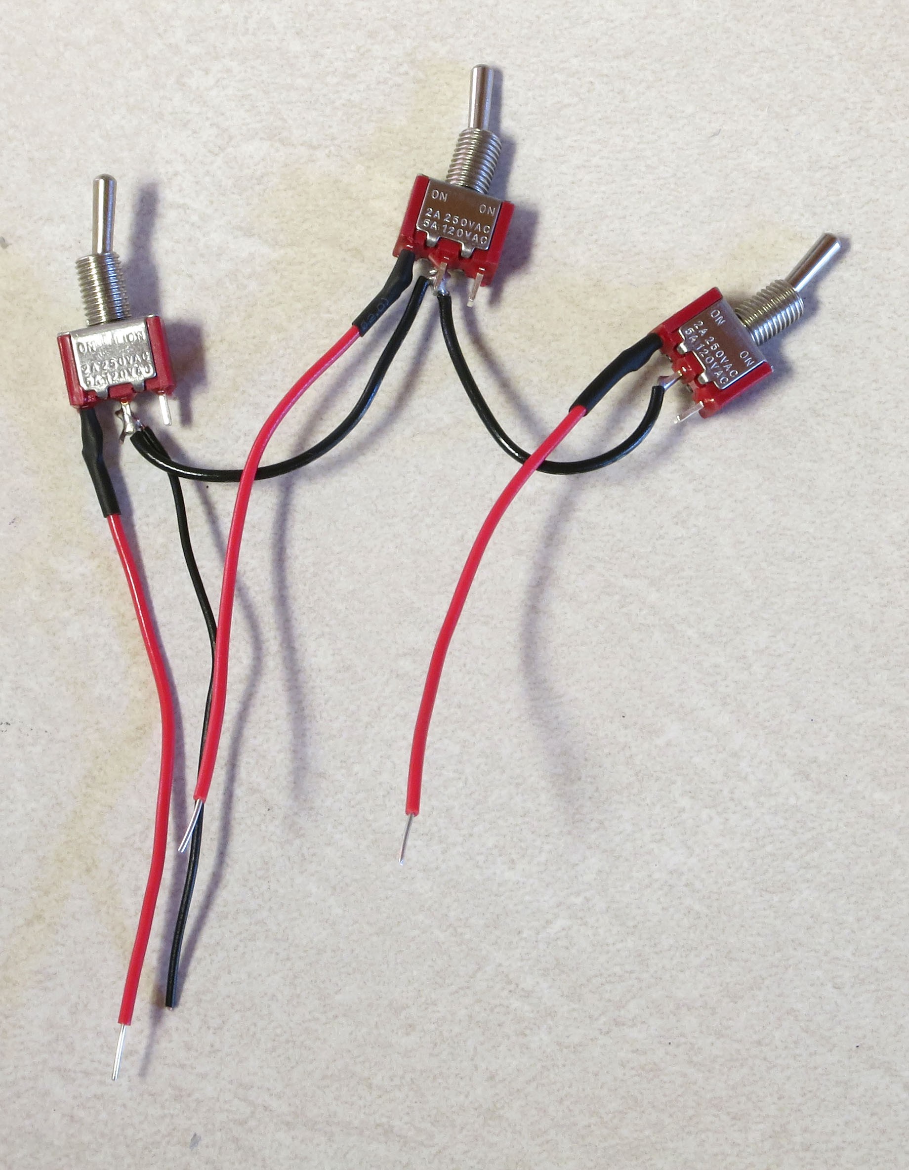
Solder a red wire to the left terminal of each toggle switch:
![]()
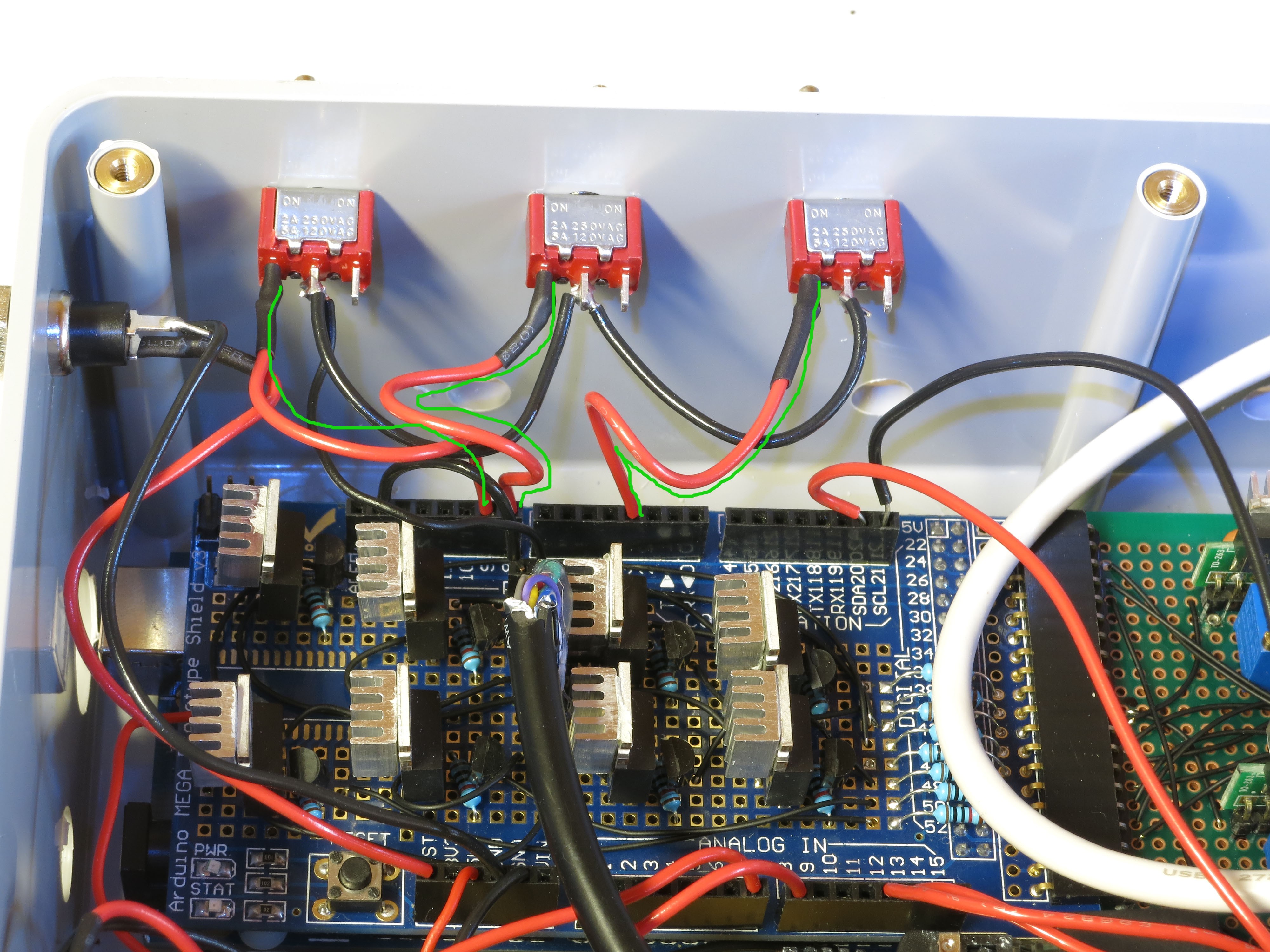
Install the three toggle switches into the holes on the rear panel. Then plug the ground wire into the open hole on the double header on the MOSFET shield:
![]()
Install the left red wire into Arduino header 9; center red wire into Arduino header 8; right red wire into Arduino header 3.
![]()
Last step in the control box assembly is to stick the rubber feet onto the bottom. If a screw sticks out farther than the feet, you’ll need to trim it to a shorter length:
![]()
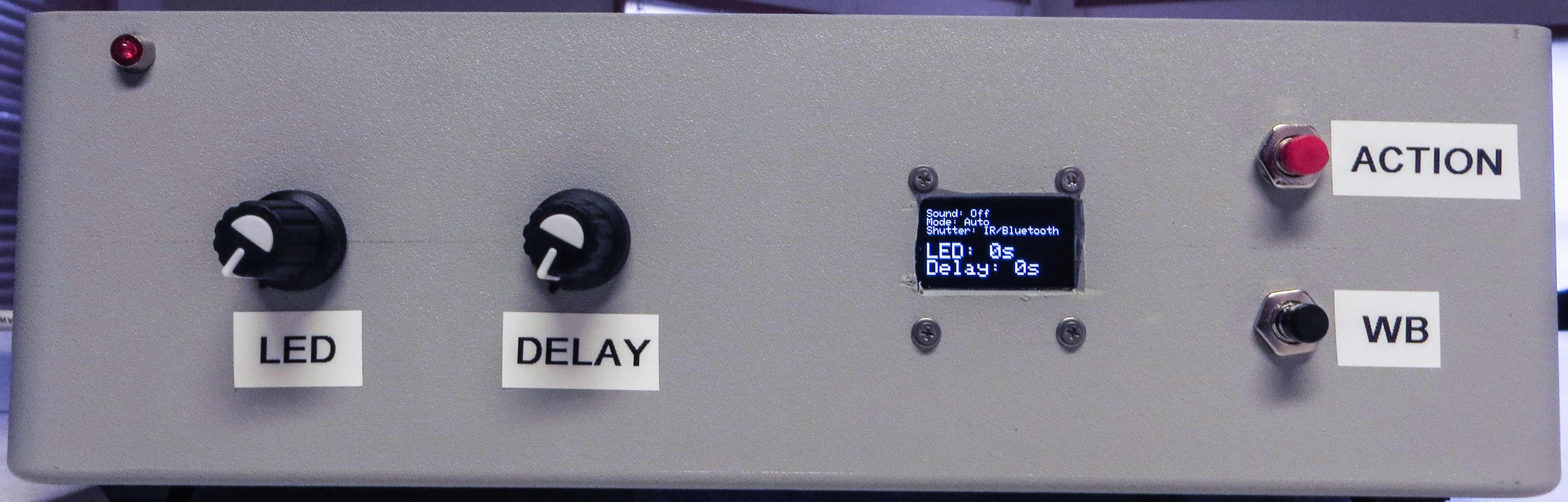
Hey – control box is pretty much done! Except I put labels on the controls and jacks to identify them. I’ll go through the functions now as a sneak preview of the operating manual.
Front panel:
![]()
LED: Sets the length of time the LED is lit, to allow the camera to take the photograph.
DELAY: Sets the length of time between the LED going off, then going back on again. This is to allow the camera to process and save the photography.
OLED display: Various relevant pieces of information
ACTION: Starts the actual process of turning on LEDs for the RTI data acquisition.
WB: This turns on the LEDs in the top row in sequence, useful for setting the exposure parameters and the White Balance (hence WB).
Right panel:
![]()
The Ethernet cables from the RTI dome plug in here, positive (red) on the right, ground (black/white/whatever) on the left.
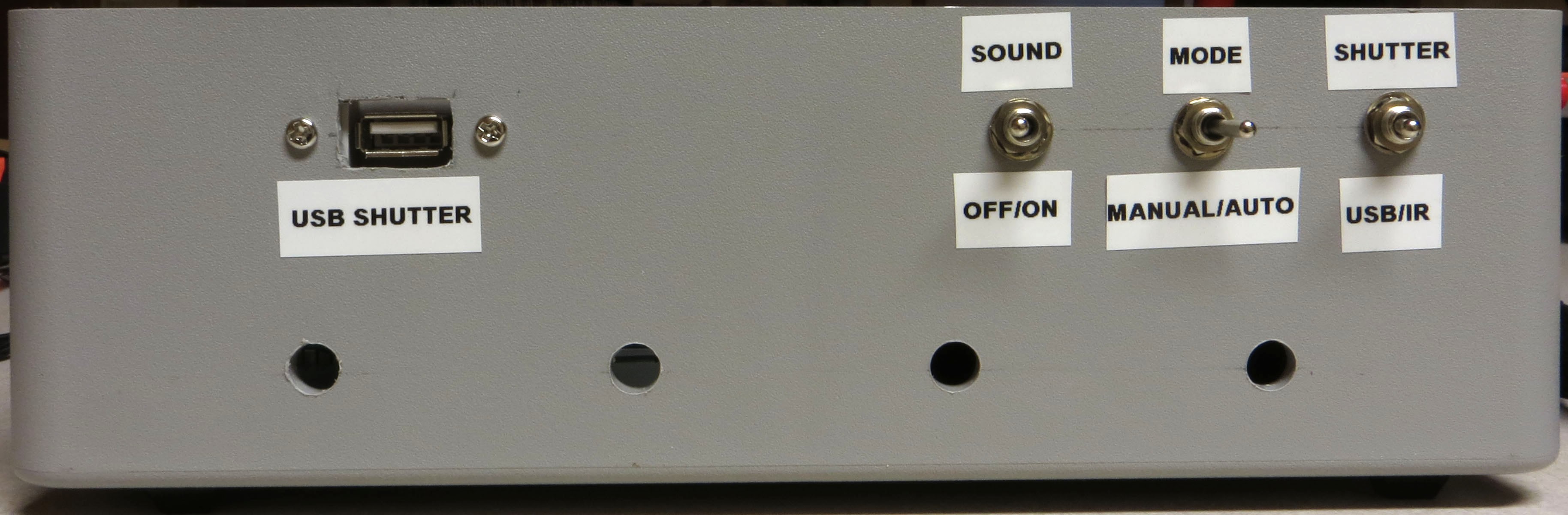
Rear panel:
![]()
USB SHUTTER: This is where you plug in a cable that has either a mini-USB connector (for Canon cameras with CHDK to control the shutter), an IR LED (for cameras that support IR remotes), a custom remote connector (for cameras that support a wired remote), or a servo control cable (for cameras that have no built-in remote capability). These will be described in more detail in an upcoming step.
SOUND OFF/ON: Controls whether the built-in beeper makes sounds or not.
MODE MANUAL/AUTO: In Manual mode, you need to manually press the camera shutter, then advance to the next LED light. In Auto mode, the control box automatically fires the camera shutter, then advances to the next LED.
SHUTTER USB/IR: In USB mode, the shutter is controlled through a USB cable (either CHDK or a custom remote connector). In IR mode, the IR LED plugged into the USB jack controls the shutter. If you’re using Bluetooth control (also described in an upcoming step), you will need to have this switch in IR position.
All of these switch functions are set in software, so if you decide you’d rather have a switch do something else, you can modify that in software.
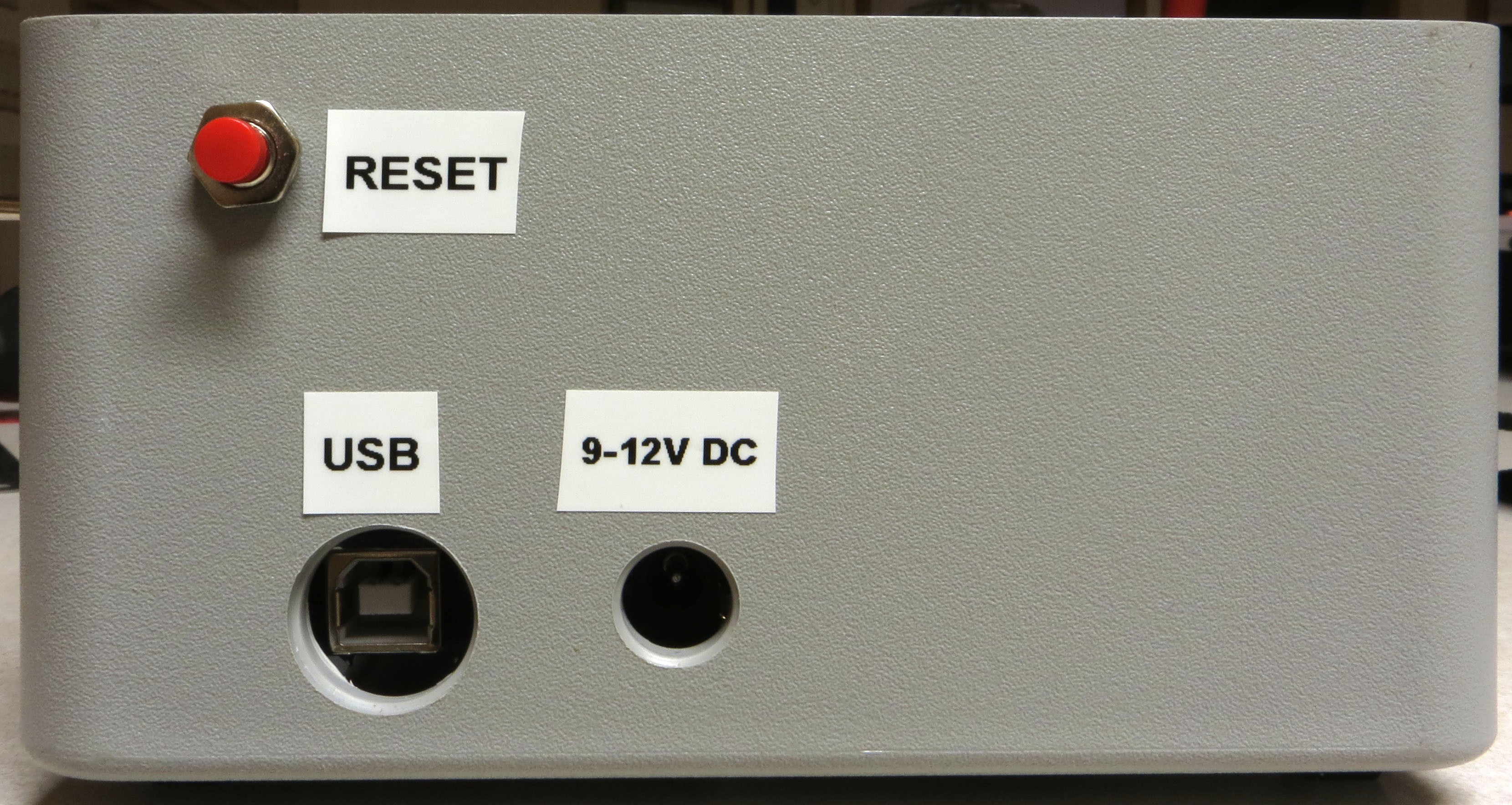
Left panel:
![]()
RESET: Resets the Arduino, stopping all running operations, and restarting the software from the beginning. Useful if something goes wrong.
USB: Connects the USB cable that runs to a computer, for uploading software programs.
9-12V DC: Main power jack plugs in here. It’s a center-positive 2.1 mm ID / 5.5 mm OD jack if you want to get technical.
-
29Step 29
Now that the control box has been assembled, the big question is, “Does it work?”. You can test the basic output to the RTI LED dome by connecting it to the control box, uploading either the “Dazzler” or “Serial_Test” programs, and seeing if the LEDs light up as they should. But neither program relies on any of the control box controls, switches or knobs, to work. You could upload the main RTI control program, and see if the box works, but that program doesn’t have any diagnostics to help you if something isn’t working right. So I’ve written a small program, “RTIMage_Controls_Tester”, to help with debugging hardware issues. It’s in the Files section of the Hackaday.io page; unzip the folder into your Arduino documents folder then upload it to the Arduino. It will work fine with only power from the USB cable, you don’t need the main power plug.
Note: The first section assumes you’ve installed the OLED display. If not, don’t worry – there’s an option described towards the end for control boxes with no OLED.
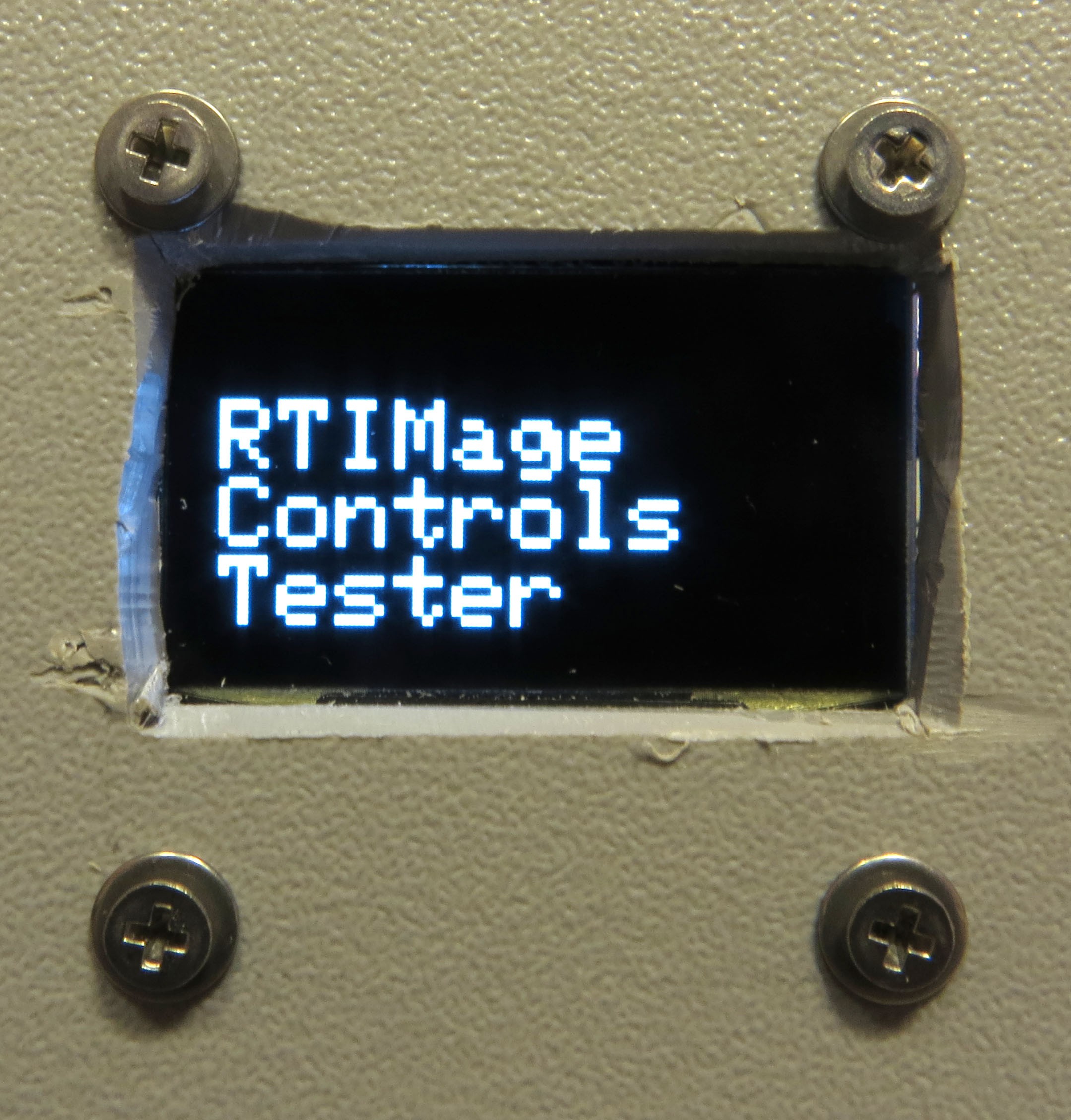
You’ll get a splash screen with the name of the program:
![]()
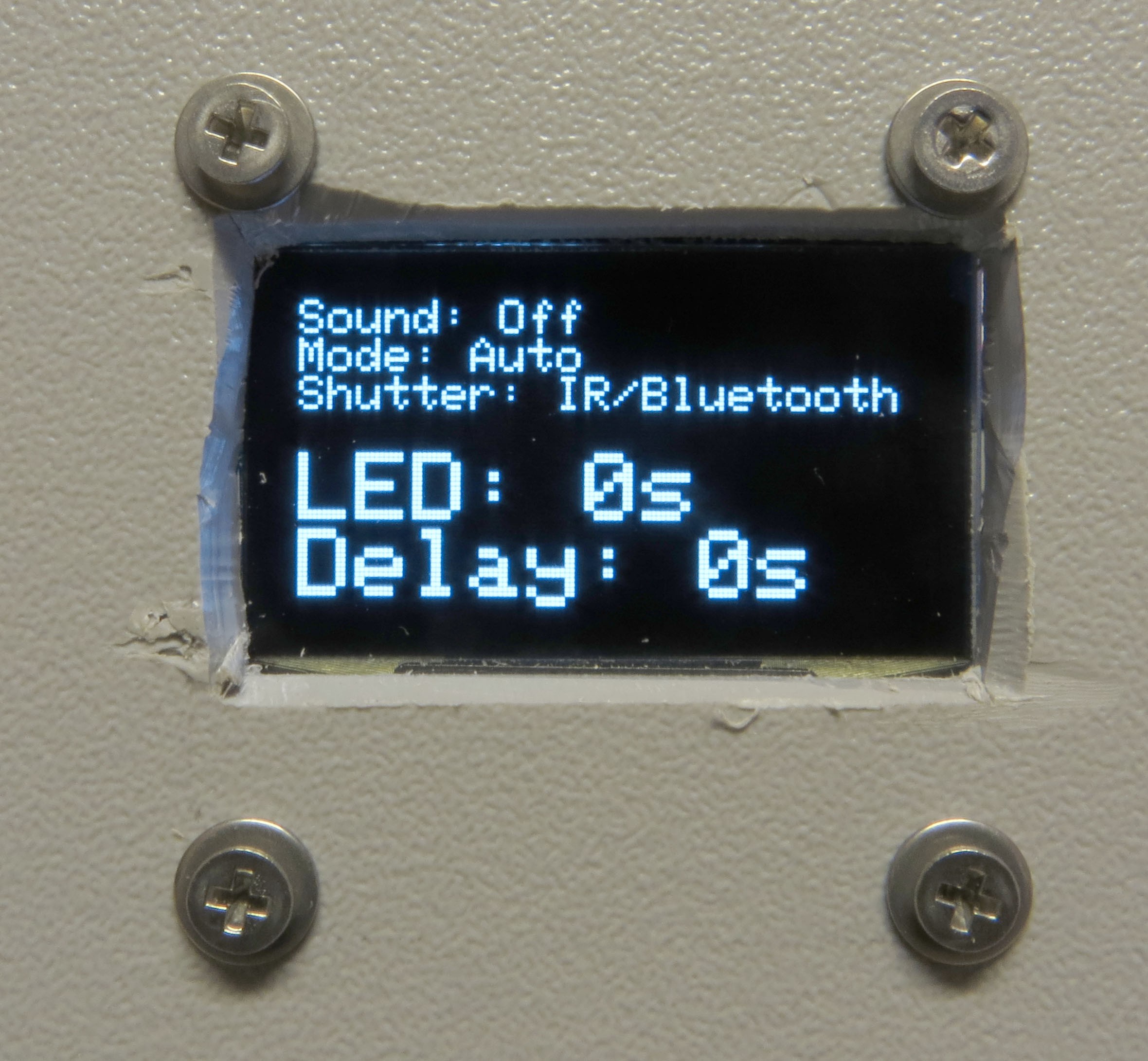
After a few seconds, you’ll get a status screen showing up:
![]()
The top three lines indicate the status of the three toggle switches on the back of the control box. As you flip these back and forth, these status lines should change to reflect that. If they don’t, check to make sure that the ground wire connected to these three switches is properly connected, and that the red wires attached to each of the switches are in the correct Arduino pin header.
The bottom two lines reflect the status of the two potentiometer knobs, LED (left knob) and Delay (right knob). These have been arbitrarily set in the program to go from 0 (turned all the way to the left) to 100 (all the way to the right). So the screen above indicates that both knobs are turned all the way to the left:
![]()
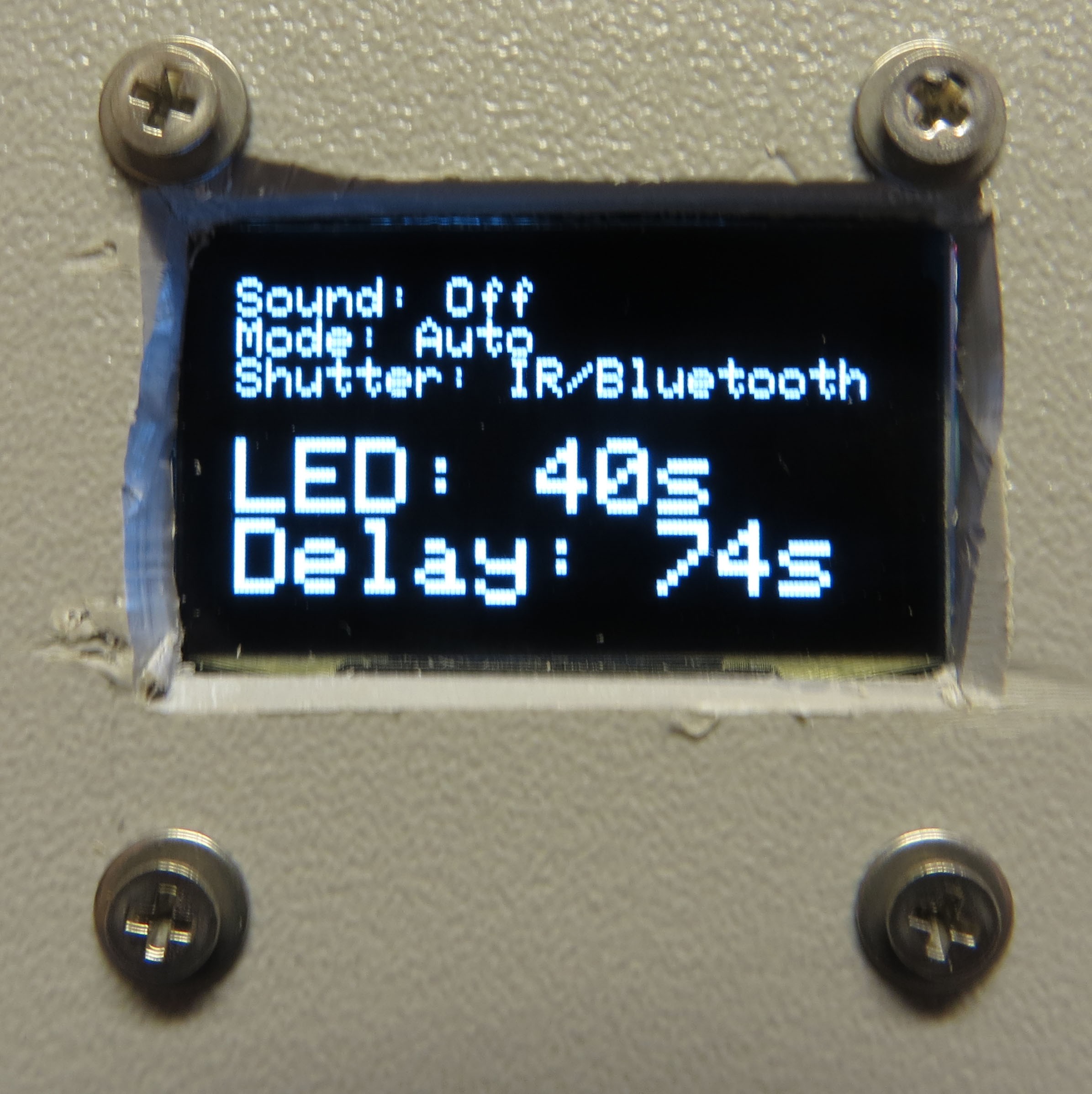
If I turn both knobs a random amount to the right:
![]()
The status screen should reflect a change in the two values proportionate with how far you’ve turned the knobs:
![]()
If both knobs have no effect, one likely candidate are the wires from the potentiometers going to the +5V and ground headers on the power board; try checking/changing those first. Also check to make sure the wires are in the correct Arduino pin headers. If one works but the other doesn’t, check the connector from the inoperative potentiometer to the Arduino board to make sure it’s seated firmly in the correct Arduino pin.
For the two buttons on the right, Action (red) and WB (black), press and hold each one separately. When you depress the Action button, you’ll hear a short beep; as long as you keep that button depressed, this message will show up on the display:
![]()
Similarly, for the WB (white balance) button, you’ll get this:
![]()
After releasing either button, the screen will go back to the status display.
If pressing a button has no effect, check that the wires from the buttons are firmly in their proper connector, both the wires to the Arduino and the wire to the ground header.
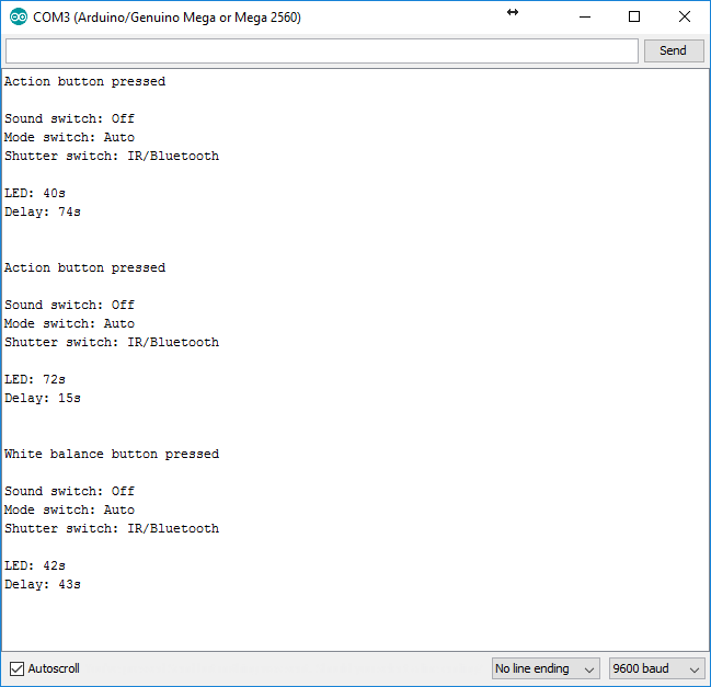
If you don’t have an OLED display, there’s another way to check the status of the toggle switches, potentiometers, and push button switches. In the Arduino IDE, enable the Serial Monitor from the Tools menu. When you press either the Action button or WB button, the status of all switches and potentiometers will be printed out:
![]()
To check the controls for proper operation, change their setting, then press one of those two buttons again. If you press a button switch and nothing happens, that likely means that one or both of those buttons are working properly, and you need to check their related connections.
One more step, and then you can close up the control box for now.
-
30Step 30
When acquiring an RTI dataset with the RTI LED dome, all of the lights need to be the same intensity. This is done by setting all of the output currents controlled by the CAT4101 chips to the same value. This step goes through the process of doing that.
The CAT4101 current is controlled by an external resistance Rset that runs between pin 4 and ground. The higher the resistance, the lower the current. The CAT4101 datasheet has this graph and table that shows the relationship between Rset and output current:
![]()
![]()
The RTIMage control box you’ve built has two resistances connected in series to every CAT4101 as Rset. There’s a fixed resistor of 560 ohms that makes sure you don’t exceed the maximum rated current for the CAT4101 of 1 amp. There’s also a 5k trim pot connected as a variable resistor, so that you can set the current for any value from about 1 amp down to about 100 mA (0.1 A). Why set a current value less than the maximum?
- There are some cases where you don’t need full light intensity. I’m working on using USB microscopes to do microscopic RTI with this system, and full light intensity fully saturates the image sensor on at least two models I’ve tried; I have to reduce current down to 150 mA before the sensor is no longer saturated.
- If you’re going to use the system in portable battery-operated mode, turning down the current will increase battery life.
- The more current you run through an LED, the hotter it gets, and the shorter its lifespan. This is the least critical factor, though. Each LED is only going to be on for a few seconds at most, so it’s not going to get very hot. Lifespans for LEDs are measured in thousands of hours of continuous use, during which time it can get quite hot even with a decent heat sink. Even if you assume a comparable lifetime with intermittent use at cooler temperatures, you’re talking about the ability to run millions of RTI data acquisitions before any visible degradation in LED intensity takes place.
- On the flip side, if you need to stop down the aperture to get maximum depth of field, you’ll probably want to increase the current to maximum intensity in order to get the shortest possible exposure time.
I usually set the current level for my domes at 700 mA (unless it requires a lower level). 700 mA is the “nominal” maximum continuous operating current specified by the datasheet for white Cree LEDs with a color temperature less than 5000K, which are the ones used in this dome. This is more than bright enough for short exposure times with both my 12” and 18” diameter domes, and likely would be fine for larger domes as well. However, since the LED operation isn’t continuous, currents up to 1 A are fine as long as the LED isn’t on for more than a few seconds; it just won’t get hot enough to degrade. I’ve used LEDs running at 1 A for many runs, and had no problems at all. One way to choose the current level for your dome is to use the lowest current that gives you reasonably short exposure times, but no greater than 1 A. Keep in mind that the camera will be in a fixed, rigid position, not moving at all. If the camera isn’t moving, exposures of up to a second or more can be considered “short”, since there isn’t any motion blur with a fixed, rigid camera.
Okay, say you want 700 mA of current output – how do you set the RTIMage control box to output that? I’ve written an Arduino program that will help with that, and you can use that program immediately, but there’s a step you can take that will speed up the process enormously.
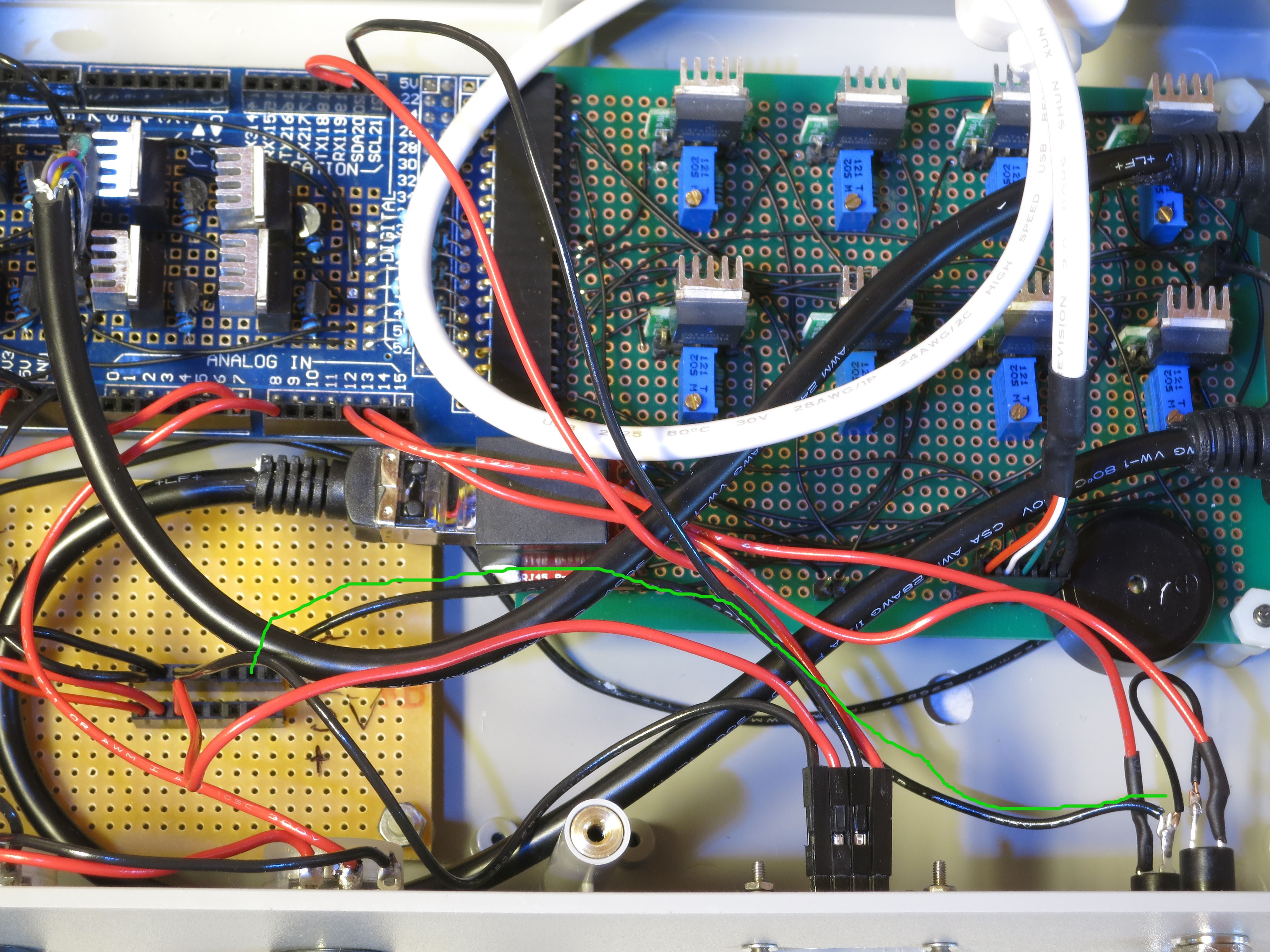
First off, decide what current you want. In my case, 700 mA. Use the curve or the table above to determine what the correct value of Rset should be. I used the curve, and estimated that the Rset value should be about 800R. On the CAT4101 board in the control box, on the right side, there’s a two-pin header that has one socket occupied by a ground lead running from the high voltage power supply. Cut a piece of black wire, trim off the insulation on both ends, and stick one end into the free socket in the header (circled in red):
![]()
Grab your multimeter (set in resistance measurement mode), and connect the ground probe to that black wire.
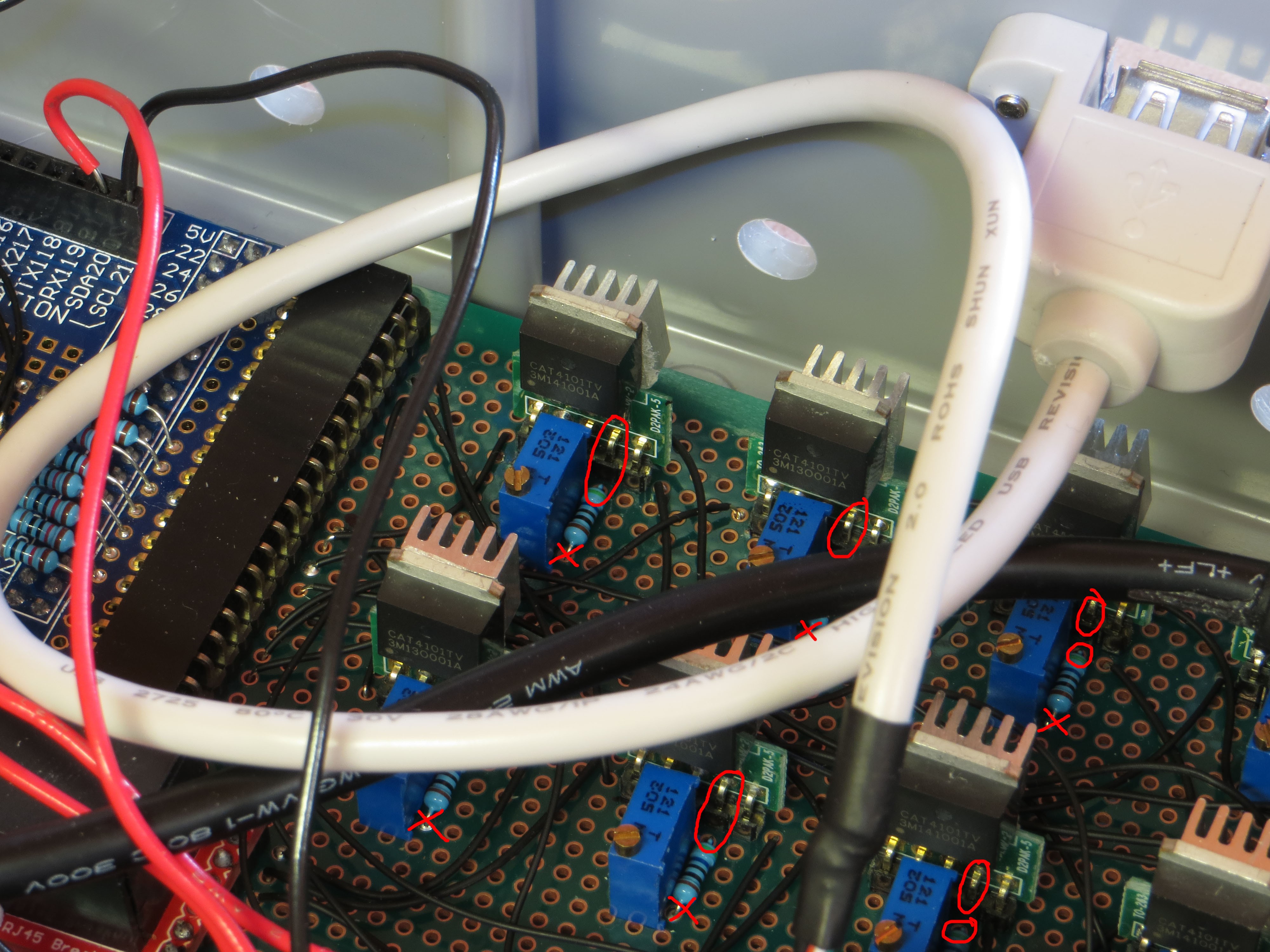
To measure the Rset for each CAT4101 chip, you’ll need to touch the red positive multimeter probe to either pin 4 on each CAT4101, or to the 560R resistor lead at the base of the CAT4101. In the picture, I’ve circled in red either a pin 4 connection on the CAT4101, or the resistor lead at the base of that pin; the Xes indicate resistor leads that you shouldn’t use, since any resistance measurement there will only measure the potentiometer resistance, not the combined 560R-potentiometer resistance:
![]()
Here I am touching the resistor lead at the base of this CAT4101 chip, and getting an initial resistance reading of 3.1 kilo-ohms (3100R) on my multimeter, meaning I need to reduce the potentiometer resistance substantially. Set the range on your multimeter so that it shows a real value; in this case, I started on the 20K range, and increased the sensitivity when I got down below 2K ohms.
![]()
If I couldn’t reach that resistor lead, I could touch the pin lead directly above it for the same purpose. It’s important that you not touch any other leads/connections, just the one connected to Rset. It’s also helpful to have two people on this operation, one to control the probe, the other to adjust the resistance. I’ve done it by myself, but it requires some contortions.
To adjust the potentiometer resistance, turn the little screw on the blue trim pot next to the CAT4101 counter-clockwise to reduce resistance, clockwise to increase it; use the multimeter reading to determine when you’ve gotten to the right value. It doesn’t have to be an exact match to your target resistance, since you’ll almost certainly have to adjust it further using the true current value. Even if you’re way off, don’t make a large number of turns on the trim pot screw without monitoring the resistance. It is possible to ruin a trim pot by turning it too many times past either the minimum or maximum level. And that would be bad. Minimum level for Rset is 560R, the fixed 560R resistor plus 0 from the trim pot; maximum is 560R plus 5K from the trim pot, 5560R. They may be a bit higher or lower than these two values, depending on the accuracy tolerances of the resistor and trim pot.
So I reduced the Rset value for this CAT4101 down to roughly 800R; I then repeated the process for the other 7 CAT4101 chips. The output currents are likely very close to each other with just this basic adjustment, but for the best matching of currents from different chips, they need all to be adjusted to have the same current value.
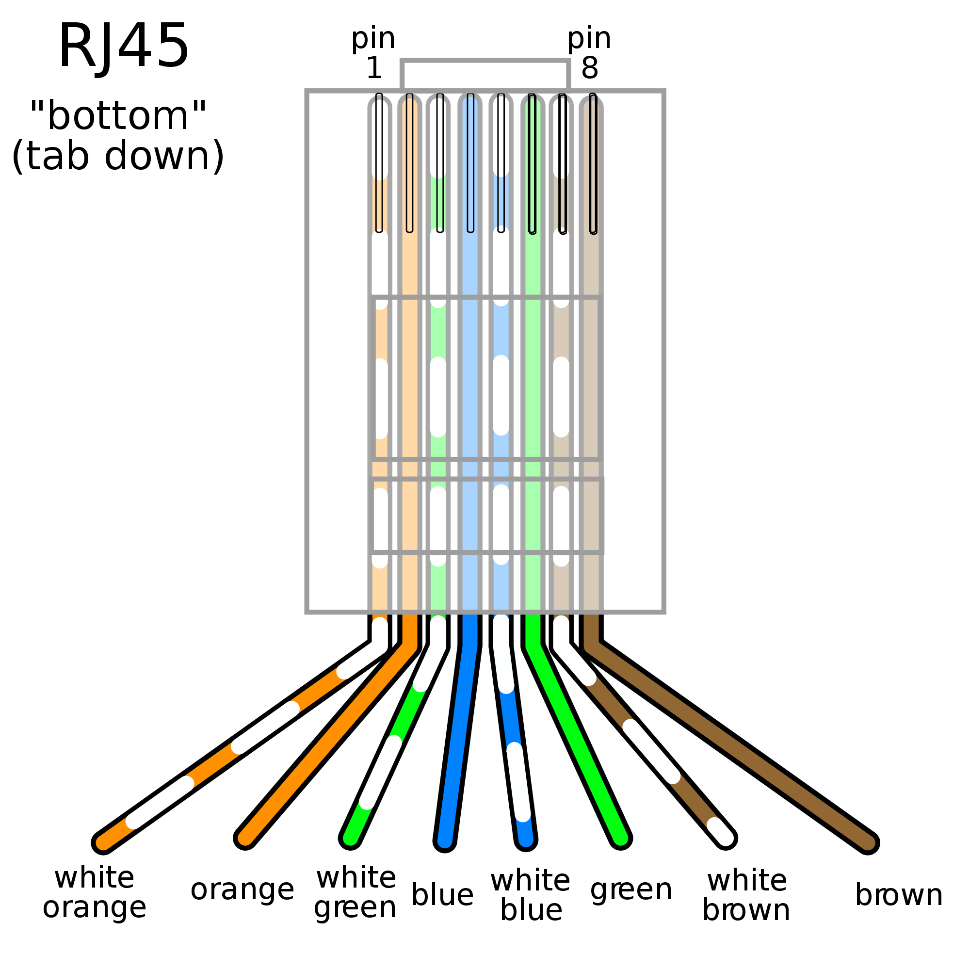
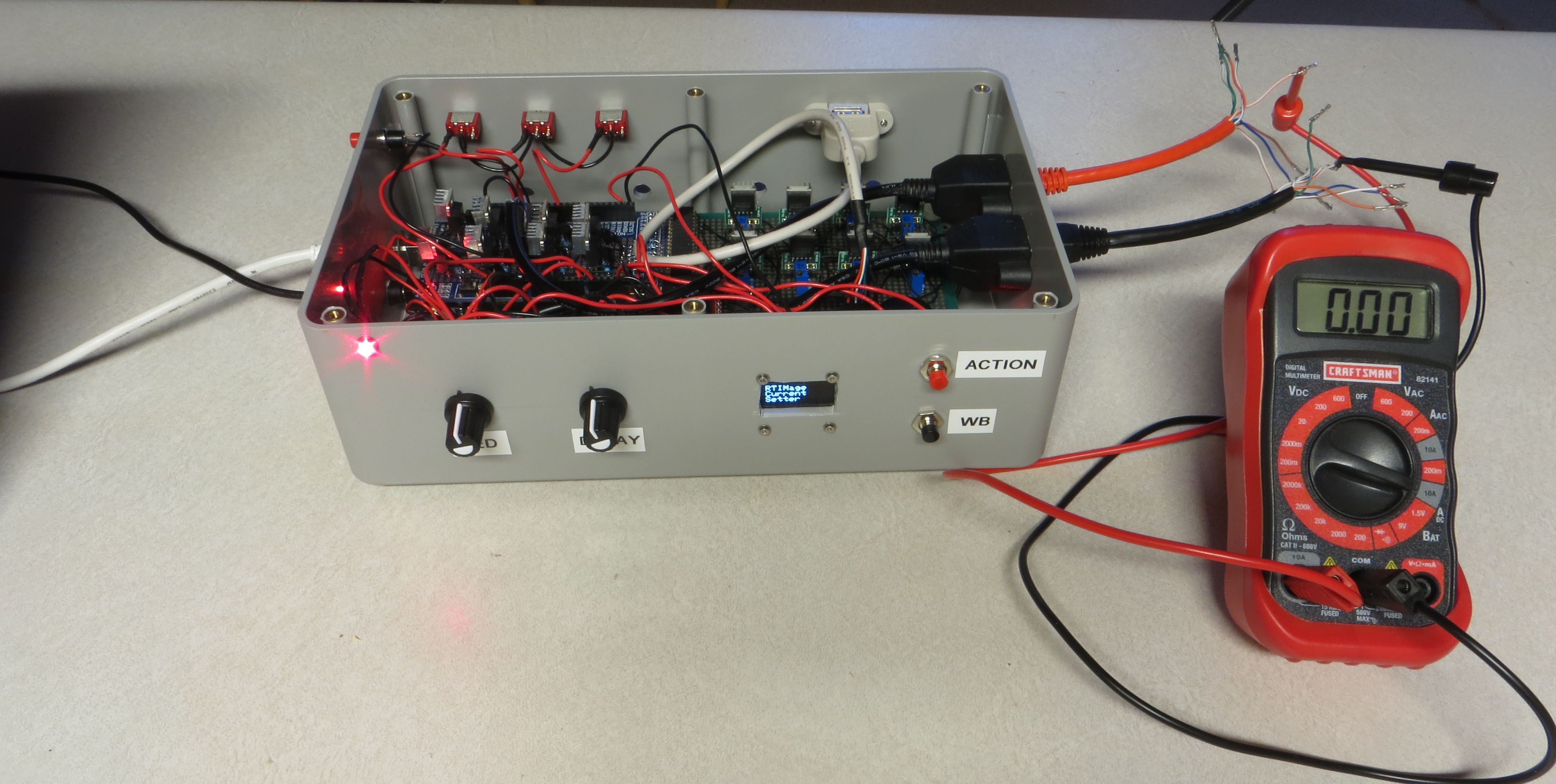
I’ve written a program called RTIMage_Current_Setter that will aid you in setting output currents. Upload this program to the Arduino in the control box. To set currents, you will need to have the main power supply plugged into the control box – the USB cable will not supply output power. You will also need to plug the two Ethernet test cables (which you made in a previous step) into the Ethernet connectors on the right side (“red to the rear”, “close to the ground”). You will also need to set your multimeter in DC current measurement mode, have a current range set that can measure your target current value, and have the jacks in the correct positions. With my multimeter, the standard jack positions are only good for the 200 mA current range; I had to move the positive probe to a separate jack marked for 10 A, and set the current range to 10 A. You will be attaching the positive red probe to a single wire on the red Ethernet connector; with the black ground probe, you will be attaching it in order to each of the 8 wires coming from the Ethernet ground probe. You’ll probably be following the standard color code for Ethernet wires to determine pin 1, pin 2 … pin 8 in order.
![]()
If you have an oddball cable color scheme, you should follow that instead, doing pins 1 to 8 in the correct order for that cable.
Here’s a picture of my setup. I have the red positive multimeter cable running to the white/orange wire on the red (positive) Ethernet test cable (pin 1), and it will stay there for the whole process. The black ground multimeter cable is attached to the orange/white wire (pin 1) on the black (ground) Ethernet cable for the first current setting, but will be moved to pins 2-8 in succession to set the current value for all CAT4101s.
![]()
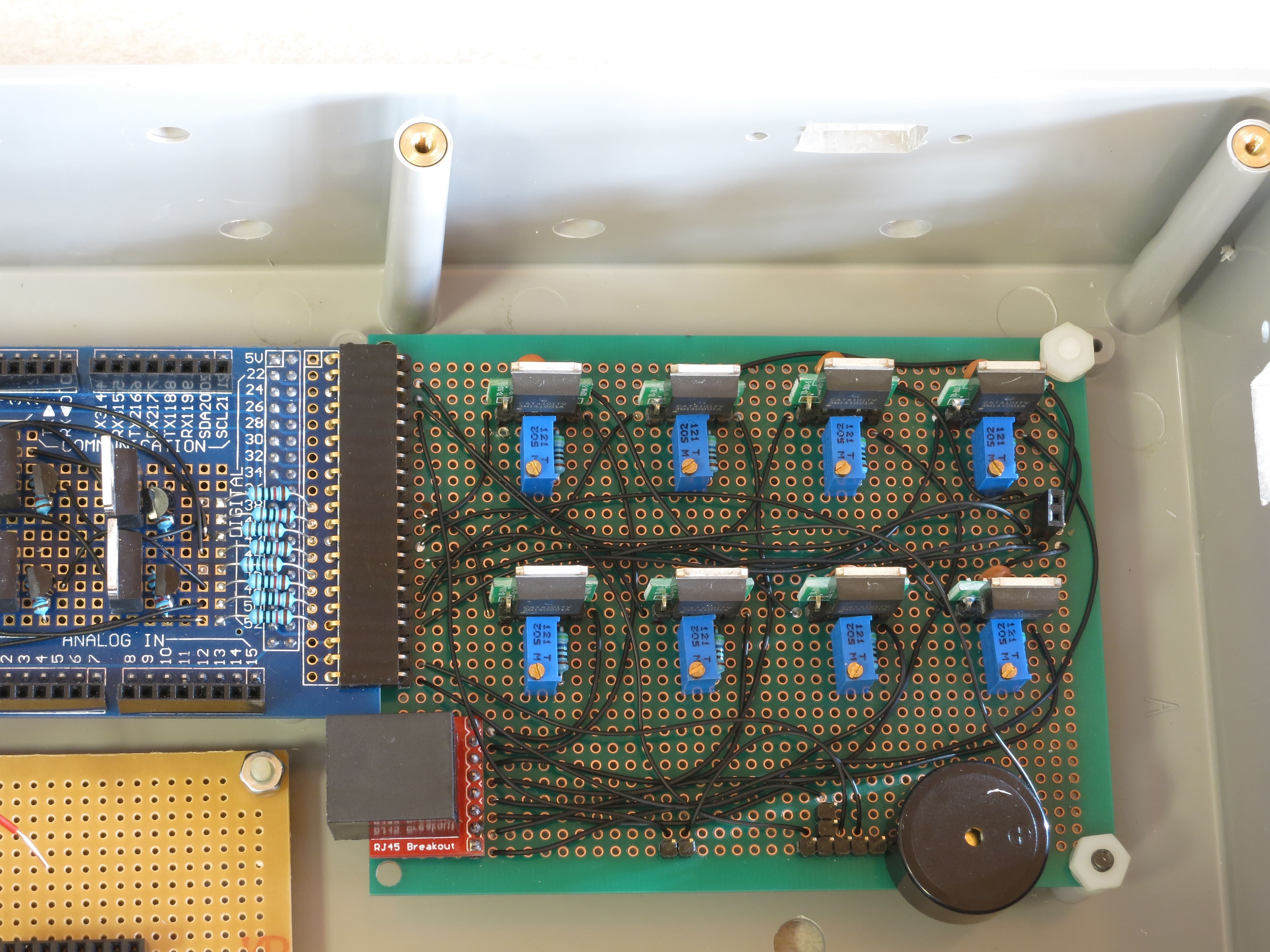
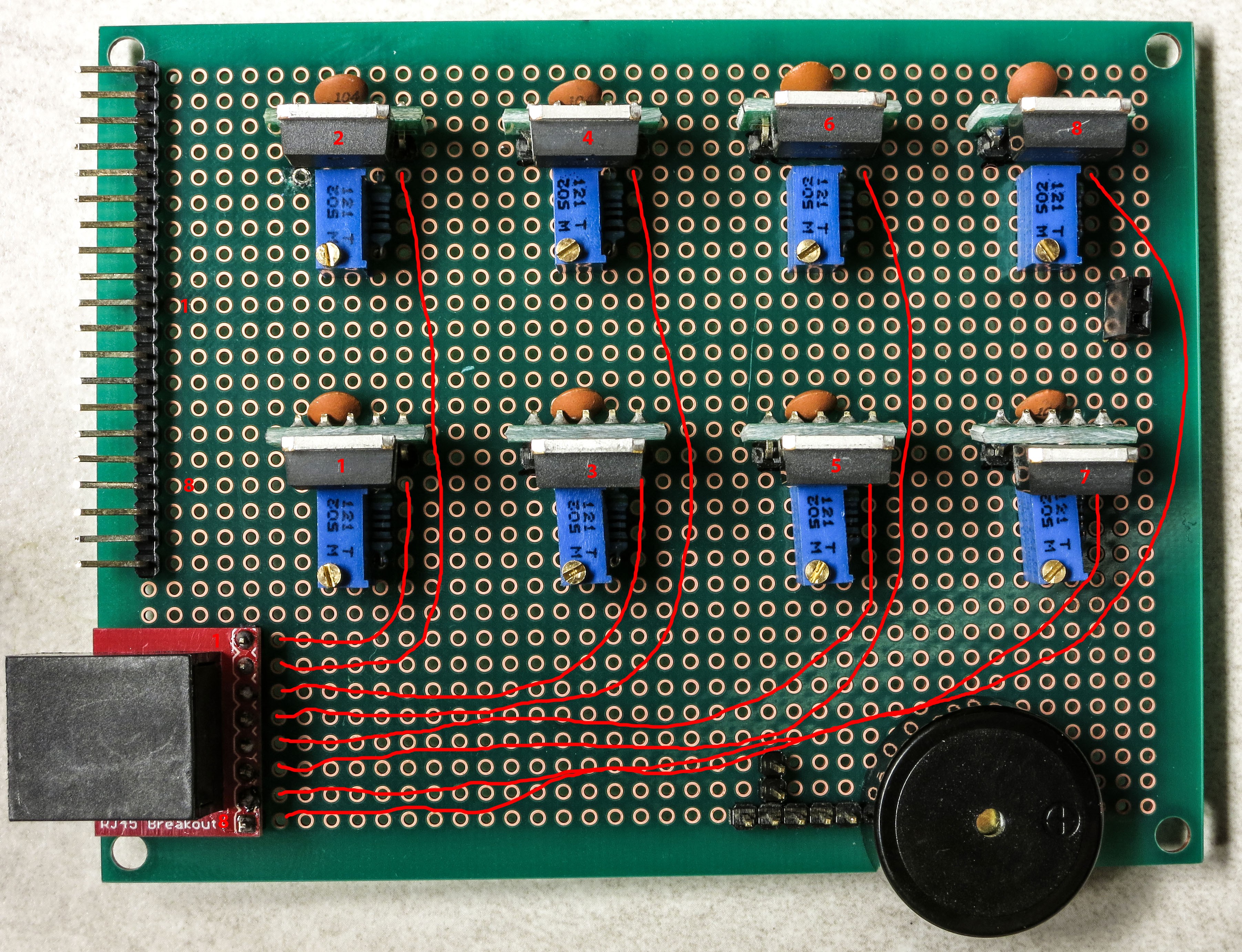
How do I know which CAT4101 corresponds to which pin number? I pulled up this handy picture from a previous assembly step, that labels the CAT4101s on the board with their matching pin number:
![]()
The immediately-following steps assume you have an OLED display installed. If you don’t, there are related instructions at the end, but read this section first anyway.
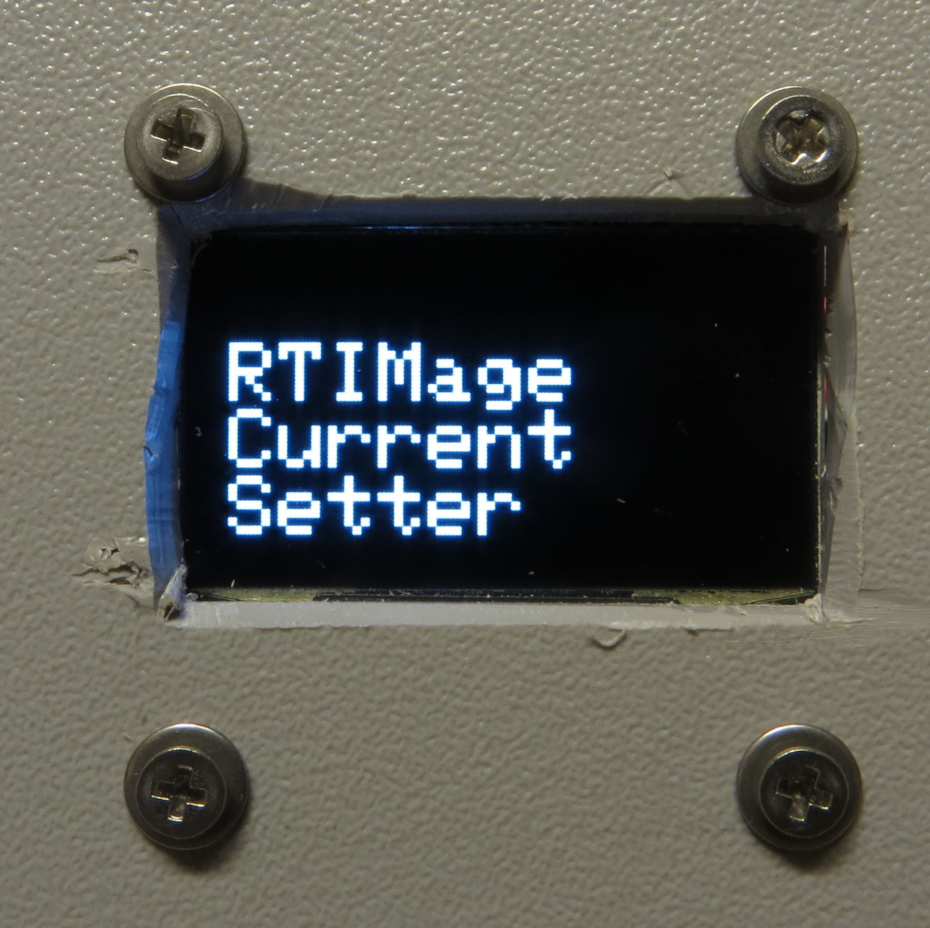
When you load in the RTIMage_Current_Setter program, you’ll see this splash screen on the OLED display:
![]()
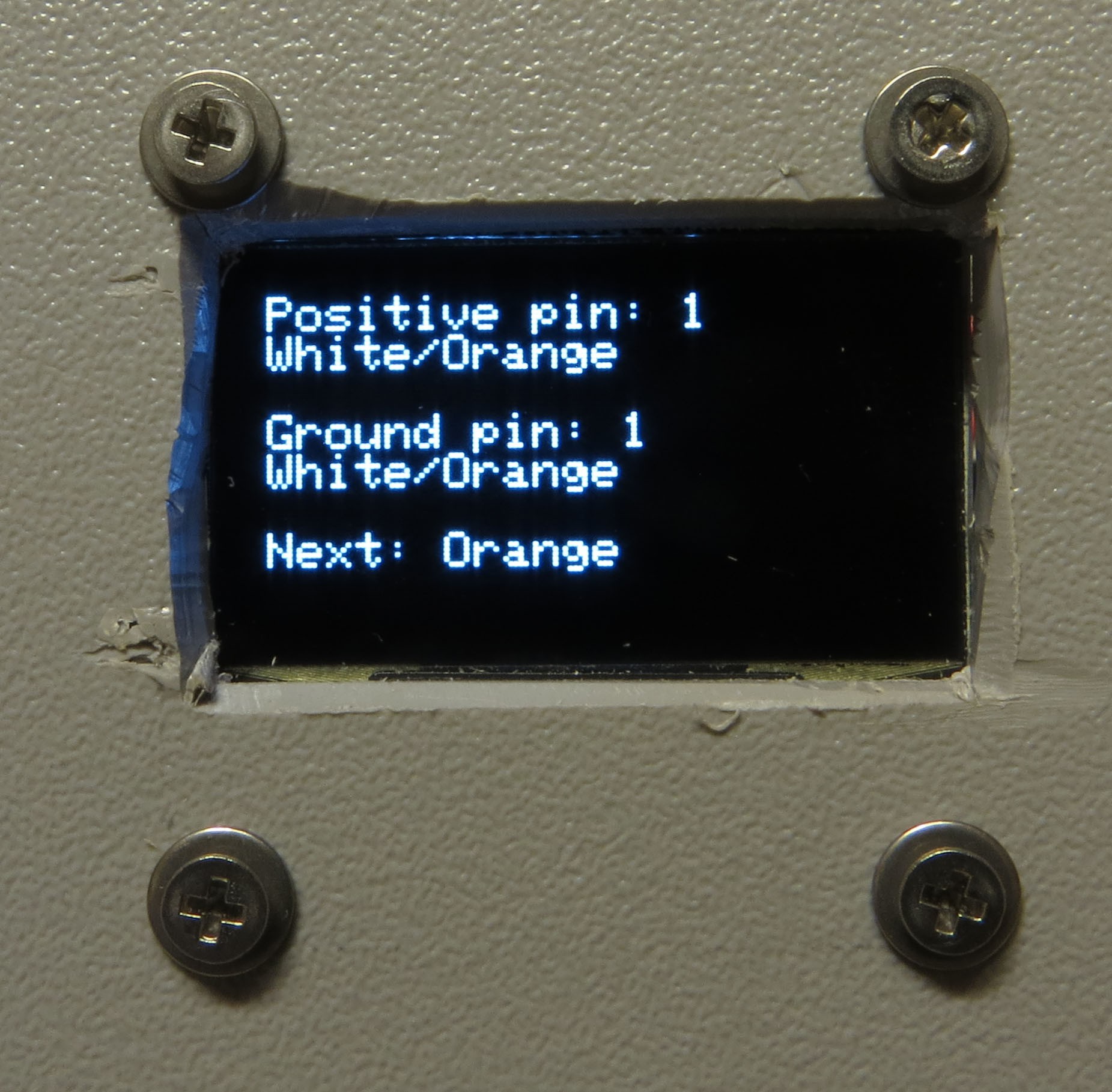
To turn on the current to ground pin 1, press the red button; you’ll see the screen change to:
![]()
The top lines indicate which pin / wire color you should have the positive multimeter lead connected to. This will always be the same. The next set of lines indicate which pin / wire color you should have the ground multimeter lead connected to. This will change as you go from the first pin to the last pin. The color of the next pin wire will be indicated at the bottom.
Pressing the red button will also turn on the current for 3 seconds, then turn it off. It’s set to turn off to prevent possible overheating issues with your multimeter; my model says that you can only measure 10 A of current for a maximum of 30 seconds before you have to let the multimeter cool off for 15 minutes. These systems typically measure current by running it through a standard resistor and measuring the voltage; since power goes as the square of the current in this situation, 1 A of current will create 1/100th the power dissipation of 10 A, so overheating shouldn’t be a problem. However, keeping the flowing current down to a minimum is still a good idea.
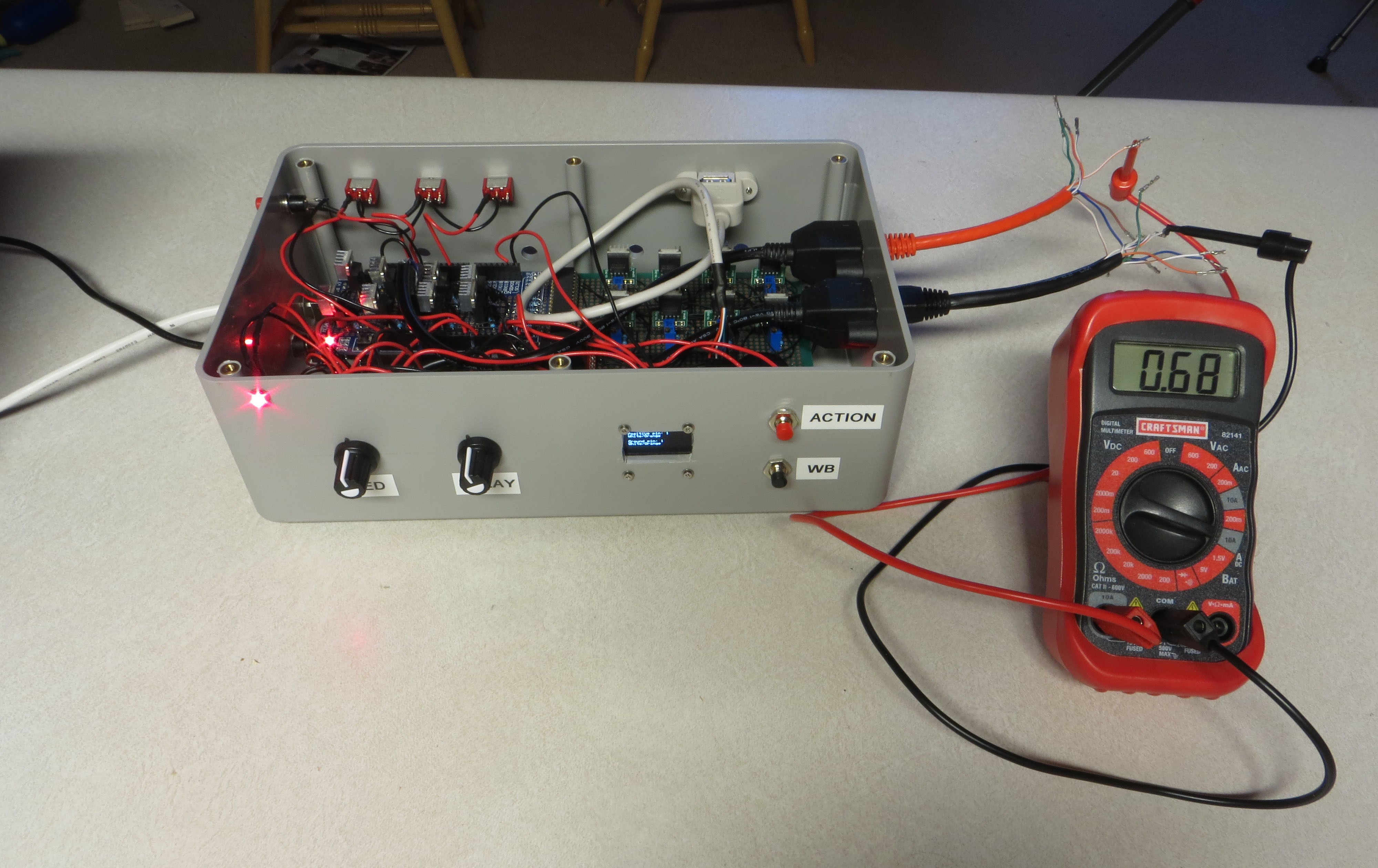
So, I pressed the red button, and the current flowing through ground pin 1 showed up on the multimeter (in amps):
![]()
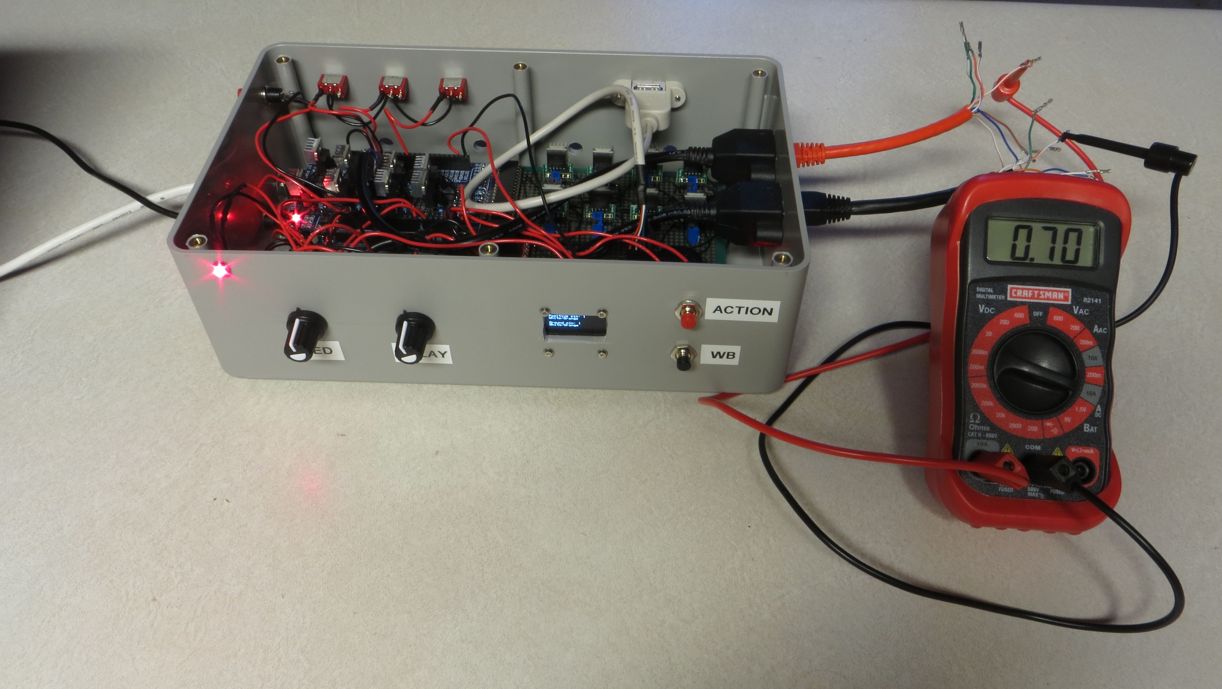
Hey, pretty close to the desired value of 700 mA (0.7A). While the current turns off after 3 seconds, you can turn it back on for the same pin by pressing the black button. I turned the trim pot down a touch to reduce the resistance / increase the current, then pressed the black button:
![]()
Looks like the desired value. Since the multimeer only reads to two decimal places, the current could conceivably be anywhere between 695 mA and 705 mA, which is +/- 0.5%, pretty decent. If I wanted to get closer, I could keep the current on continuously by pressing the black button continuously, and then tweak the current from below until it just changes from 0.69 on the multimeter to 0.70.
When you’ve got the current set for one pin, time to move on to the next one. The status screen will show you the next color wire you need to hook the black multimeter cable to. Do that, and press the red button; the status screen will advance to the next pin / color wire, and turn on the current for that pin (as well as showing the color wire of the next pin). Repeat the current setting process until you get to the last pin/wire; the status screen will let you know when you’re there. When you’re done with the last wire, pressing the red button will take you back to the splash screen; if you need to, you can start the current setting process over again by pressing the red button.
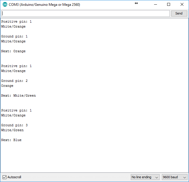
If you don’t have an OLED display installed, turn on the Serial Monitor from the Tools menu in the Arduino IDE; you'll need to have the USB cable connected to the Arduino. Each time you press the red button, you’ll get messages like the one below that tell you which is the current pin / wire color, and what’s the next wire color:
![]()
When all the pins are set to the same current, you can put the lid on the control box and screw it down. Write down the current value you set somewhere; you’ll want to have it handy when uploading the main control software to the control box.
Affordable Reflectance Transformation Imaging Dome
A simple and inexpensive way to image and analyze subtle surface details on objects.


 Clean up the debris from the drilling (and the marks you
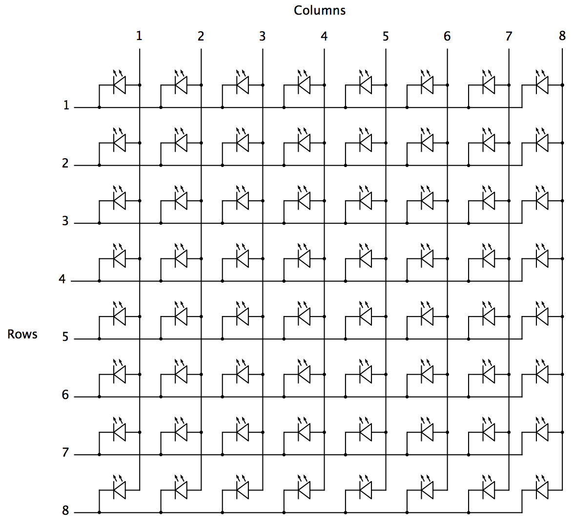


Discussions
Become a Hackaday.io Member
Create an account to leave a comment. Already have an account? Log In.