-
31Step 31
While there are ways you could use the RTI dome by lifting it up and placing it over the object you want to photograph, it makes more sense to have the dome/camera stationary, and have a way to easily swap multiple objects in and out of the system for easy data acquisition. One solution is put the dome on an elevated stand, and I’ll be describing the simplest possible stand design I can think of. There are reasons you might want to modify this setup having to do with how you mount the camera, and I’ll talk about that in the next step. But even there, these instructions will help you with that process.
Grab a wooden dowel about 1” or so in diameter, preferably a soft wood like pine. Cut it into 4 6” long segments for the stand legs:
![]()
Cut a square board with dimensions equal to or slightly larger than the outside diameter of the RTI dome, including the rim. My dome has an OD of 12”, plus a rim of 0.75”, for an outside diameter of 13.5”; I added 1/8” for luck, and had a square board cut with dimensions of 13 5/8” by 13 5/8”. My first stands were made out of wood, but I’ve had problems finding wood flat enough for this purpose. I have switched over to using ½” thickness medium-density fiber board (MDF); it cuts and works like wood, but even large pieces are usually flatter than wood panels. Just don’t get it wet (or paint/seal it if it will be anywhere it might get wet).
Draw diagonal lines from the corners of the board to find the center:
![]()
Measure and cut out a hole centered on the middle of the board, with a diameter roughly equal to the inside base diameter of the dome; doesn’t have to be exact:
![]()
You could attach the dowel legs right now with glue, screws or nails, if you don’t plan on transporting the stand. However, I like to make the dowel legs removable, so that you can break down the stand to a smaller size.
Drill ¼” holes near the corners; I measure about 5/8” along the edges, and drill at the intersection:
![]()
You now want to put ¼-20 threaded inserts into the top of the dowels. There are two varieties of these: screw in (left) and press fit (right):
![]()
![]()
With screw-ins, you drill a hole of a specified size (5/16” for ¼-20 inserts), then screw the insert into the hole. Tip: the slotted end, which you might think is used with a screwdriver to screw in the insert, actually goes in first. With press-fit, you drill a hole just a small bit smaller than the insert, then hammer it in. Screw-ins are more expensive than press-fits, and I had a few press-fits left over from a previous project, so I decided to use those. Turns out I didn’t have a drill bit slightly smaller than the press-fits, so I drilled a slightly larger hole and then glued them in place. Hammered them down before the glue dried so that they would be flush with the top of the dowel:
![]()
Also did a crappy job of putting the hole in the center with a drill. Tip: use a nail or screw to make a small starter hole in the exact position you want the hole, and first drill a pilot hole with a smaller diameter bit than the ultimate hole size.
With threaded inserts, you can run a 1” ¼-20 bolt (with washer) through the main bolt, and screw in the dowel legs:
![]()
Put the dome on, and it fits:
![]()
But it’s too easy to knock the dome off, or to the side. So, cut some ½” dowel pieces about an inch long, and glue them in next to the dome (be careful not to use too much glue that will ooze out and glue the dome in place as well):
![]()
![]()
In the past, I’ve reinforced these with screws from the bottom, but I don’t really believe that’s necessary (and it runs the risk of splitting the pin). If the pin gets knocked off, it can just be glued back on.
For placing the surface of the object you want to photograph at the correct height, the base of the dome, you could build a box or stand out of wood/MDF, or even stack books up to the correct height. I use a lab jack, which lets you easily adjust the height to any required level:
![]()
This is a just a basic, simple design. You can leave it as is, or paint it in some festive color (I chose white). After painting, I also added some rubber pads on the bottom of the dowel legs, both for slip resistance and vibration dampening; I used some old computer soundproofing foam I had lying around.
For some options for camera mounting, you may need a larger version of this (see the next section for more info). And for the small 12” dome I’m documenting the build of, I’m going to write up construction of a far more flexible and capable stand than this. Soon.
-
32Step 32
When acquiring RTI data, you need to have the camera pointing straight down at the object being photographed, through the hole at the top of the dome. Which brings up the question, how do you mount the camera above the dome so that it’s fixed, rigid, and pointing straight down? Here are some possible ways, some of which I’ve tried, some of which I haven’t (but which could work). One of these may work for you, but you may also have to come up with your own unique camera mounting system
1.Use a tripod that lets you mount the head on the bottom. Like this model, and many others:
![]()
Orient the camera so that it’s facing straight down, and position it so that it’s looking through hole at the top of the RTI dome. I use this method with my smaller domes when I have to shoot with a larger camera like a DSLR:
Works fine:
Although the pistol grip on this tripod is pretty weak – it’s just barely able to hold up this Nikon D90. If I buy another tripod like this one, I’d choose a standard tripod head that should be more stable (as long as I can adjust it to let the camera point straight down.
Advantages:
-You may already have a tripod that can do this.
-Strong enough to support large cameras.
-Flexible enough to support a variety of camera sizes (compact to DSLR).
Disadvantages:
-If you don’t have a tripod like this, you’ll have to buy one.
-Requires a fair amount of table space even for a small dome, and more for a larger dome.
-Not practical for very large domes (> 24” in diameter)
2. Use a pivot tripod or tripod extender
Like these guys:
![]()
![]()
Haven’t used either of these, so can’t comment too much on advantages/disadvantages. Seems to me that the extender might be susceptible to vibrations that might blur the image, and the pivot tripod might have problems supporting a camera if it’s extended too far (unless you can add a counterweight).
3. Camera stand
Here’s one you can buy off the shelf:
![]()
Haven’t tried this one directly, although a friend used a similar concept on a dome I built for him. Seems like a decent solution, although you may need to modify your dome stand to get it to fit. Another option would be to adopt the “pole” part of this design and attach it directly to the stand.
4. PVC stand
½” PVC pipe – is there anything it can’t do? Here’s one of the earliest camera stands I made for an 18” dome, out of PVC pipe glued together (with foam rubbed on the bottom to prevent movement and vibration). The camera is held in place with a ¼-20 screw in the back of the T-junction. The white unpainted pieces of PVC are not glued in place, so that I can rotate the camera into position.
![]()
![]()
![]()
![]()
Advantages:
-Cheap, parts readily available.
-Strong enough to hold cameras up to DSLR sizes
Disadvantages:
-Requires a much larger stand to accommodate both the dome and the camera holder
-While reasonably steady, you’ll definitely need a stable, vibration-free surface to put it on
-Only accommodates one camera size at a time. You can raise it with supports, I suppose, but not sure how stable that would be.
These are just a few ideas – you may have to come up with your own design to accommodate your camera. For most of the photography I do, I use a compact camera, and I’ve come up with a simple, stable holder design that should work well with any dome size:
![]()
Instructions in the next step.
-
33Step 33
Here’s the camera holder from the previous step:
![]()
Small, neat, secure, easy to install – perfect for the right camera. What is the right camera? It needs to be a reasonably small camera that will lay flat/parallel on the wooden board when you insert the lens assembly into the hole drilled in the board. Here’s my Canon S110 from the front:
![]()
Nice flat front, lays very flat as long as the hole is big enough to contain the lens and the ring outside it.
Here’s my Canon SX260:
![]()
Curved front, which you think might disqualify it. And yet, if I lay it on a board with a hole cutout just big enough for the lens assembly to fit, it also lays parallel to the board, and works great as a camera for the RTI system. So the moral is, you have to try the camera before determining whether it will work with this style of holder or not.
Remove the holder from this older dome, and the holes that hold it in place become visible:
![]()
This hole is 2.5” in diameter, specified so that a telescope eyepiece focuser could fit exactly (the notch at the bottom of the hole was cut for the focuser gear train):
![]()
![]()
Why am I mentioning this? Because I used the eyepiece focuser as a template for drilling holes into both the dome, and into the wooden camera holder. The focuser is intended for use with a USB microscope, for high-magnification RTI work. What if you don’t have a focuser? Or, in my case, what if you had the hole drilled to a size other than 2.5” in diameter, like the 3” for the dome I’m using for this build? How do you position the holes to be drilled on the dome, and how do you get the holes on the wooden board to match up?
The following is my solution. If you think of a better one, let me know.
Start by getting a board cut to square dimensions, large enough to hold the camera when the lens assembly is centered on the middle of the board. I have a board already cut to about 5” x 5” (a bit less):
![]()
and my Canon S110 will fit on that:
![]()
Draw lines between opposite diagonal corners, and the center will be where they intersect. Draw a circle around the center that has the same diameter as the hole in your dome, 3” in this case:
![]()
Now figure out where to space/place the holes. In my case, I want to space the holes with the same distances as the screw holes for the telescope focuser, so that I have the option of using the focuser with this new dome. The holes are spaced about 74.5mm apart on the focuser, so using Pythagorean geometry, I calculate that the holes should be about 52.7mm away from the center of the block (sqrt(2*74.5^2)/2). I mark drill hole positions at those distances from the center:
![]()
In the likely case that you’re not worried about the option of installing a telescope focuser, you can pick any radius outside the hole and inside the board to mark the positions. But be careful not to put them in a location where you might unintentionally drill through an LED or some wiring in the dome. The distance I’m using should be pretty safe for most domes, but check to make sure.
Use a nail or small drill bit to make a precise starter hole, then drill a 1/8” hole through each of the drill marks:
![]()
If you have a hole saw the same size as the hole in your dome, you can now use it to drill out a hole in this board. Aligning the hole in the board with the hole in the dome, and taping the board in place (see later on in this instruction step), you can use this board as a jig for drilling holes in the dome.
But, if like me, you don’t have a hole saw big enough, you have to go through a few more steps. First, lay some blue painters tape on the floor sticky side up, then place the board on that tape. Use more tape to fix the board to the floor:
![]()
Now place the RTI LED dome upside down on top of the board, so that the board is visible through the hole. Move the dome around on the board until the drawn circle is aligned evenly with the edge of the dome hole:
![]()
In the above picture, there’s still a bit of the drawn circle visible on the top left, but none on the bottom right, so it’s not perfectly aligned yet.
Once aligned, put tape on the inside to help hold the board in place:
![]()
Use the first piece of tape, laid sticky side up on the floor, to further fix the board to the dome. Then remove the tape holding the board to the floor, and flip it right side up.
![]()
This may look good, but I wanted the board a bit more clockwise, so that the center line between the holes lined up just to the right of the Gorilla tape at the base of the dome. So I repeated the process, and got this:
![]()
Exactly where I wanted it, and a useful orientation for a more advanced stand I’ll be documenting further on.
Put more tape on the board to hold it firmly in place, much more than I did below:
![]()
Double-check one last time to make sure the holes aren’t above LEDs or wiring inside the dome. Then using your 1/8” acrylic drill bit, use the holes in the board as a guide to drill 4 holes into the top of the dome:
![]()
See that double hole at lower left? That’s because I didn’t have enough tape holding the board in place while I was drilling, and it slipped on the last hole. I had to re-align the board and re-drill the hole in the proper location. I then used a step bit to clean out that double hole:
![]()
Acid test is, does the telescope focuser fit? Putting it inside the main hole, and putting screws through the focuser and the dome:
![]()
Three of the four screws went in perfectly; the fourth one (visible on the right) was a bit off. Fixing that is as simple as enlarging that hole in the dome a bit, which I did.
You should now mark the wooden board you used for aligning these holes as a permanent template, and only use it for creating new boards. Here I’ve taped the template on top of another board, using it to mark a fresh set of drill holes:
![]()
Use a 1/8” drill bit through the template holes to mark the drill positions underneath, making small pilot marks.
![]()
Draw diagonal lines between opposite holes to find a central point.
Next, take the camera and measure the size of the hole you’ll need to drill in this board for the lens assembly to fit through. I used a pair of calipers, but a ruler should get you close enough:
![]()
I measured a hole diameter of 2.05”, so that’s the minimum diameter hole I need to cut in the wooden board for it to fit through. Don’t worry if it’s a bit big – you’ll have additional control over its final position. Use whatever cutting implement you want. I had a hole saw 2” in diameter, and used that; if the hole was a bit small, I planned on sanding it out until it fit.
Tip: When using a hole saw, remove it frequently to blow out the sawdust. If the saw teeth fill with sawdust, it won’t cut any further.
As it happened, the hole saw had enough cutting loss that the camera lens assembly fit perfectly into it without further trimming.
![]()
And checking the fit of the board into the dome holes using #6 screws, it fit perfectly as well – no need to enlarge any of the holes:
![]()
To attach the camera securely to the board, and align it correctly, this holder uses the ¼-20 tripod mounting hole on the base of the camera. Cut a rectangular 1/2"-thick piece of wood the height of the camera when inserted into the hole (2 cm in this case):
![]()
On the left, you want it to clear the washer the screw will go through. On the right, you want it to go at least as far as the tripod hole plus a bit more:
![]()
Pencil mark above shows where I cut this piece. Ideally, the piece will allow you to open the base door of the camera to replace the battery or SD card:
![]()
Possible on my Canon S110, but not possible on every camera; my Canon SX260 didn’t allow for this.
In the small block you’ve just cut, measure where the center of the tripod hole is on the camera, mark it on the block, and drill a 5/16” hole there. You can then insert a 1” ¼-20 bolt with washer through the hole, attaching it to the camera.
![]()
Making sure the camera lens is fully inside the central hole, loosen the bolt, press the wood piece until it’s flat against the board, then tighten the bolt. Remove the camera/wood piece assembly, put a small amount of general purpose glue (Elmer’s, Weldbond) on the bottom of the wood piece, then put the camera/wood assembly back so that the camera is lined up as evenly with the drill holes as possible. Press firmly down, then let the glue dry before unbolting the camera. Not too much glue – you don’t want it to ooze out and glue the camera to the board as well, though general purpose board should peel off the camera in case that happens.
Put the mounting screws in, and check to make sure that the battery/SD card door still opens with the screw in place. For this camera, there’s enough clearance:
![]()
If it didn’t clear, I could always countersink the screw head to lower a bit. In fact, I did that with another screw on the board that slightly blocked access to the zoom control on the top of the camera:
![]()
Putting the camera holder back on the dome to check the fit again:
![]()
Looks good. The fit is pretty snug with just the screws through the holes, but if I need extra security, I use a neoprene washer, steel washer, then brass knurled nuts to attach it internally to the dome:
![]()
Don’t tighten the knurled nuts too much – just enough to make them snug.
And the camera still fits:
![]()
I painted the camera holder later on – white on top to match the dome, black on the bottom. I found that painting the bottom white caused some problems with very reflective objects – they reflected the image of the bottom. Painting the bottom black fixed that problem.
This is obviously only a practical solution for smaller cameras like point-and-shoots; DSLRs can’t be attached this way. For whatever camera you want to use, you may have to find/build your own unique holder.
-
34Step 34
For creating an RTI dataset, you first need to acquire a set of photos taken at different lighting angles – that’s what the RTI-Mage system is for. It lets you take up to 64 photos at different lighting angles, which can be processed into an RTI data file. There are a number of ways that the RTI-Mage allows synchronization of the camera shutter with each individual LED light at a different angle:
Manual: For cameras that don’t have any remote capability supported by the RTI-Mage. The LED lights and shutter are advanced manually.
Automatic: A number of modes support automatic shutter triggering in synchronization with the LED lights, including
CHDK: RTI-Mage supports cameras that can run the Canon Hacker’s Development Kit through a USB cable connection, using the Remote Parameters settings.
IR Remote: RTI-Mage supports Canon, Nikon, Sony, Pentax, Olympus and Minolta cameras that have an IR remote capability, using a custom-built cable.
Wired remote: RTI-Mage can support some cameras with wired remote connectors, using a custom built cable.
Bluetooth: Using the Adafruit Bluetooth HID module, RTI-Mage can support cameras that are controlled by computer software. Examples would include USB microscopes and Canon/Nikon cameras that use manufacturer’s custom software.
Servo: For cameras that don’t support any other remote mode, a small servo can be used to mechanically depress the shutter automatically. NOT YET SUPPORTED – I’M WORKING ON IT.
Here’s some more information about each mode:
Manual: This mode is for those whose camera does not support any of the automatic modes listed below; the Mode switch will need to be in the manual position. In this mode, an LED is lit manually with a press of the Action button, and stays on long enough to allow you to press the camera shutter button manually to take the picture. If the light goes off before you press the shutter, you can turn it back on with the WB button. When the photo is shot, press the Action button to advance to the next LED in the sequence. For good results, the camera and dome will need to be stably/firmly mounted in place, so that neither moves when the shutter is pressed. Otherwise, the result may be a bit blurred, though it may be difficult to see that. More instructions on using this mode will be in a future step.
Automatic: There are a number of automatic mode options for the RTI-Mage system; which one you use depends on which kind of camera you have. Some of them require either special software installed on the camera or a computer, or a special cable to be used; these section will describe how to configure each camera/cable as required.
- CHDK (the Canon Hackers Development Kit) is custom firmware for many Canon cameras that can be temporarily loaded from the SD card to the camera, and allows remote triggering of the shutter through the standard mini-USB connector. You can find more information about CHDK at its wiki page, including a list of compatible cameras and installation info. Note that the wiki has many sections that are out of date. Also note that many recent Canon cameras do not work with CHDK – check the list of compatible cameras at the wiki to see if yours is. eBay or the Canon refurb store are good sources for older, CHDK-compatible Canon cameras.
The simplest way to install CHDK on your Canon camera’s SD card is to use the STICK utility (http://www.zenoshrdlu.com/stick/stick.html). Note that STICK can’t reformat cards in exFAT format to the required FAT32 format, and Windows won’t let you format cards larger than 32 GB in FAT32. However, the STICK page does link to several utilities that can re-format 64 GB and larger cards to FAT32. Once you’ve installed CHDK on the SD card on your computer, set it in write-protect format, insert it into your camera, then turn the power on. You should see a boot message for CHDK on your camera’s screen. Use the buttons for your camera model to access the Main Menu for CHDK- these may differ from model to model. On my Canon S110 and SX260, pressing the Play button briefly, then the Menu button, takes you to the Main Menu for CHDK. Once there, go to CHDK Settings, then select Remote Parameters. Turn on Enable Remote, set Switch Type to OnePush, and Control Mode to Quick. Exit out of the CHDK menu, and your camera is now set to fire the shutter when it receives a voltage pulse over a USB cable plugged into the USB Shutter jack on the RTI-Mage control box on one end, and the mini-USB jack plugged into the camera at the other end. The RTI-Mage camera mode will need to be set to Auto, and the Shutter mode set to USB. Once that’s done, starting the photography cycle in Auto mode will turn on one LED, fire the camera shutter, then turn off the LED and advance to the next LED for the same cycle.
This is as good a place as any to mention a possible quirk with Canon cameras. When I upgraded my Canon camera from an older 8 megapixel model to a 12 megapixel one, I was surprised to find that some of my RTI imagery with the new camera looked blurrier than with the old camera. What’s more, it wasn’t consistent – sometimes it would be pin-sharp, other times not so much. Drove me crazy, but I finally figured it out. When you first turn on the Canon camera and set a zoom level, successive pictures show a slight “drift” in the pixel location from picture to picture, a maximum distance of about 7 pixels. You don’t see that when you take regular photographs because it’s a trivial amount, and you have no reference for it. RTI combines results from multiple photographs, though, so such a small drift can have a visible impact on the results. This appears to be hardware issue, as I’ve seen it with two different Canon cameras, but not a third. There’s no solid fix, but there is a workaround. The pixel drift seems to settle out after about 30 pictures, so I shoot a set of dummy pictures first; subsequent picture sets show no signs of drift. Keep in mind that if you change the zoom level, or turn the camera off then on again, you’ll have to shoot another set of dummy pictures to fix this issue.
- For the IR remote, the RTI-Mage controller supports Sebastian Setz’s Arduino library for camera IR remote control. This supports a number of camera makes with IR remote capability, including Canon, Nikon, Sony, Pentax, Olympus and Minolta. To use this mode, you will need to build an IR remote cable to plug into the USB Shutter jack on the RTI-Mage control box (instructions below); you will also need to enable support for your camera model in the RTI-Mage software (more on this in another instruction step).
The IR remote cable is simplicity itself. The positive and ground wires from a USB cable are connected to a 940 nm IR LED, with a 100R resistor in series to limit the current to 31 mA at 5V. To build the IR remote cable, grab a spare USB cable, and cut off the end that isn’t the USB A male plug, i.e. don't cut off this one:
![]()
Strip the insulation off the cut wire end, revealing four wires: red, black, green and white:
![]()
Cut off the green and white wires – you won’t need them.
Saw a small section of protoboard off the larger piece listed in the components section. Sawing seems to be the best option, as cutting tends to make the board explode into little bits. Read somewhere someone suggesting drilling out the holes in the board to make a cut, but haven’t tried that. Take the IR LED and stick it into one side of the board, long lead (positive/anode) on the left. Bend the IR LED until the leads are flat against the protoboard:
![]()
Insert a 100R resistor into the protoboard next to the left LED lead (anode), and bend the leads as shown:
![]()
Strip insulation off the red and black wires of the USB cable. Insert the red wire into the hole adjacent to the resistor; insert the black wire into the hole adjacent to the right LED lead (ground/cathode). Solder all adjacent connections and trim off excess leads; attach the main USB cable to the protoboard with a bit of twisted wire:
![]()
Didn’t take a picture, but I globbed hot glue over all the components on the protoboard to hold them securely.
It’s hard to test whether this LED is working correctly, even when plugged in, because IR light is invisible to the naked eye. Camera sensors can detect IR light, which is why they normally have an IR filter in front to block out IR. However, this IR LED is bright enough that a camera can pick it up. Grab your digital camera, set your ISO to the highest level you have, set the mode to Auto, then turn out the lights. Plug the IR LED cable you just made into a 5V USB power supply (your computer will work fine), and point the LED straight into the lens of the camera. In the display, you should see a faint purplish glow – that will tell you that you’ve assembled the IR LED cable successfully.
![]()
![]()
Once I saw the IR LED was working, I wrapped it up in black Gorilla tape for the final packaging. Feel free to pursue a more elegant solution.
![]()
To use this IR remote with a compatible camera and the RTI-Mage controller:
1. Modify the RTI-Mage software to enable your camera make (more on this in the upcoming section on the RTI-Mage control software).
2. Plug the IR remote cable into the USB Shutter jack.
3. Set the Mode switch to Auto, and the Shutter mode to IR/Bluetooth.
4. Point the IR at the camera’s IR sensor (check the manual for its location), and then fix it in place (tape, clamp, wire, whatever).
5. Check your owner’s manual for how to set the camera to respond to an IR signal. Typically, this involves one of the timer-related control settings on your camera.
That should be it. Once that’s done, starting the photography cycle in Auto mode will turn on one LED, fire the camera shutter, then turn off the LED and advance to the next LED for the same cycle.
- A wired remote connection can be created for those cameras that support it. However, unless the camera doesn’t support IR remote capability, I would recommend you use the IR option. A single IR cable can support multiple camera modes, but unfortunately just about every camera maker has a proprietary plug/jack for their wired remote. There’s a full set of pictures and pin-outs at the Camera Remote Release Pinout list at http://www.doc-diy.net/photo/remote_pinout/, which will give you a feeling for how complicated it can be. However, for many of the cameras, the mechanism is quite simple – if you complete a circuit across one/two camera remote connections and ground, the shutter will fire. There are many ways this could be done mechanically, with relays/electromechanical switches, but the reading I did suggested that there are problems with switch “bounce” with these. Bounce means that the mechanical switch hits the other contact, bounces off, then hits again for a double-contact; this means the potential for a double shutter release. So I’m using a commonly-employed circuit that closes a circuit electronically using a chip called an optocoupler (or optoisolator). This chip has an LED and a phototransistor. When the LED is off, the phototransistor doesn’t allow any current to flow, leaving the circuit open; when the LED is on, the phototransistor lets current flow, closing the circuit. The optocoupler chip I use is the 4N35, cheap and readily available, but there are many other models you could use.
As with the IR remote, grab a USB cable and cut off the non-USB A end; strip the cable insulation off:
![]()
Cut off the unneeded white and green wires, and strip insulation off the other two:
![]()
Cut out a small piece of protoboard, and mount the optoisolator on it:
![]()
You’ll be connecting the LED pins to the USB wires, with a current-limiting resistor in series. You’ll be connecting the collector and emitter to the positive voltage and ground connections of the wired remote cable.
Insert a 100R resistor next to the positive LED pin:
![]()
Insert the red USB wire next to the resistor lead, and the black USB wire next to the ground LED pin on the 4N35:
![]()
Solder the connections together; I attach the USB cable to the protoboard with a bit of twisted wire for strain relief:
![]()
For some remote cables you can find generic plugs, like the 2.5mm stereo jacks used for older Canon camera wired remotes. For most recent cameras, though, the connectors are non-standard/proprietary. Cheapest source for one of these is to order an inexpensive wired remote for your model from eBay or Amazon, then cut off the remote switch. Strip the insulation off, and for Canon/Nikon/a few others, you will likely see three wires (this is an older Nikon cable):
![]()
One of these is the ground connector, one controls focus, and the third fires the shutter. The colors aren’t standard, unfortunately, so you’ll have to use a multimeter and the pinout diagrams from the DIY.net site to figure out which is which. In this case, blue was ground, green was focus, and red was shutter.
From experience, I know that with Canon cameras you only have to connect the ground and shutter wires to the remote to have it work correctly with the RTI-Mage. However, with Nikon cameras, both the focus and shutter wires need to be connected together in order for the shutter to fire correctly:
![]()
Insert the ground wire next to the emitter pin on the 4N35, and the focus/shutter wires next to the collector pin. Solder in place; add strain relief to the cable:
![]()
Just to secure everything in place, I globbed hot glue on everything:
![]()
And then wrapped it all up in Gorilla tape:
![]()
To test the cable, connect your multimeter in resistance mode to the shutter and ground pins on the connector, then plug it into any powered USB jack. You should see the resistance drop from infinity down to about 50R or so, which should be enough to trigger the camera shutter. Canons usually work reliably, Nikons can be a bit flakey; that’s why I prefer the IR remote, since it works more reliably with all cameras.
To use this remote cable with the RTI-Mage:
1. Plug the wired remote cable into the USB Shutter jack.
2. Set the Mode switch to Auto, and the Shutter mode to USB.
3. Check your owner’s manual for how to set the camera to respond to an IR signal. Typically, this involves one of the timer-related control settings on your camera.
That should be it. Once that’s done, starting the photography cycle in Auto mode will turn on one LED, fire the camera shutter, then turn off the LED and advance to the next LED for the same cycle. More info on this shortly.
- For Bluetooth, the camera shutter controlled via a computer program is fired using the Adafruit Bluetooth HID module. This is useful for USB microscopes, and Canon/Nikon cameras operated remotely via proprietary software. Instructions coming soon.
- Servo is a control system to fire the shutter mechanically using a rotating arm. This isn’t ready yet, hope to work on it shortly. If you’d like to try making this work on your own, start by cutting a standard USB cable to leave the USB A connector intact. Strip off the cable insulation to reveal the four wires:
![]()
Cut off the red wire, that won’t be used here. Black is ground, white is servo power, green is servo control. You’ll need to connect two jumpers on the CAT4101 board to enable both the white and green wires:
![]()
Arduino pin 27 is the servo control pin. The rest, programming and mechanical connections, is up to you for now. Hope to get to it myself shortly.
-
35Step 35
If you’ve gotten to this point, then all the hardware you need to do RTI is complete, with the exception of some minor optional extras. So it’s time to load the software into the Arduino that makes the control box fully operational for acquiring RTI datasets. The software’s name is RTI-Mage_Main_Control, and the latest version will always be in the Files section of the Hackaday project page.
But before you upload it to the Arduino, there are some constants you may want to modify, either right away or sometime in the future. Load the program into the Arduino IDE, and you’ll see right at the top a whole bunch of constants are defined. Many of them are hardware related, so if you modify those, the system may not work. But there’s a number of them that can/should be modified depending on your needs. Here are the relevant program strings, what they mean, and how you can change them.
String Current_setting="700mA";
This is a text string that shows up on the boot-up splash screen, telling people what the current output value you set earlier is. The system has no way to detect the current output setting, so you should definitely specify it here. Make sure it stays in quotes.
const unsigned int Min_Data_Transfer_Time=500;// minimum time after LED goes off to save photo data
const unsigned int Max_Data_Transfer_Time=6000; // maximum time after LED goes off to save photo data
These are the minimum and maximum values for the “Delay” time, controlled by the right “Delay” knob on the front panel. This delay is to allow the camera time to save the photo it’s just taken to memory. For high-quality DSLRs, this time can be a fraction of second; for lower-end cameras, it can take a few seconds. The values are in milliseconds, thousandths of a second, so the number above correspond to 0.5 seconds and 6 seconds. Feel free to modify either of these if you feel the values are too high or too small for your needs. Make sure you only enter an integer value, no decimal point.
const unsigned int Min_LED_Time=100; //minimum time LED is on for picture to be taken
const unsigned int Max_LED_Time=4000; // maximum time LED is on for picture to be taken; set by USB microscope time
These specify the minimum and maximum times the LED light is on during picture taking, controlled by the left “LED” knob on the control panel. This will depend on the exposure time required. Don’t increase the maximum time unless you absolutely have to, since the longer the LED is on, the warmer it gets. For example, I have these set to a wide range (100 to 8000) since one of the USB microscopes I’m using requires a long exposure time, roughly 6 seconds. However, for that system I also have the current set to a very low value of 150 mA, so it won’t get hot despite the longer on time.
const unsigned long White_Balance_Time=3000; //time for one white balance LED before switching to the next one
const unsigned long White_Balance_Max_Time=24000; //maximum total time for white balance before it turns off (to prevent LED stress)
Pressing the black “WB” button starts a long light cycle, where the LEDs in a single row are lit up in succession, each for the time specified by the White Balance time. This is to allow you to set the camera white balance, focus, and exposure parameters. The time is limited to prevent the LEDs from getting too warm, and the Max_Time is set to turn off the function after a limited time, to keep it from going forever. I wouldn’t modify these unless you absolutely have to.
const unsigned long Min_LED_On_Time=500; //Minimum on time for LED in manual mode
const unsigned long Max_LED_On_Time=4000; //Maximum on time in manual mode for LED (to prevent overheating); turn back on with white balance button. Higher values not recommended.
These are the minimum/maximum LED on times in manual mode; you set the actual value using the LED knob. Probably shouldn’t modify these unless absolutely necessary. If the LED goes off in manual mode before you have a chance to press the camera shutter, pressing the black WB button will turn that LED back on again.
const unsigned int Frequency=1000; //Sets default frequency of beeper (in Hz, cycles per second)
Sets the base frequency for the beeper in Hz; 1000 Hz was chosen as the default because it’s a balance between high human ear sensitivity and annoyance. Lower frequencies are more pleasant, but the ear’s response drops off significantly below 1000 Hz. Frequencies up to 5000 Hz have a better ear response, but sound more annoying. Change this if you like, won’t affect actual operation. And remember that there is a switch on the control box that turns off all sounds.
const unsigned int Rows=8; //Number of Rows being used (cathode connection to CAT4101s)
const unsigned int Columns=8; //Number of Columns being used (anode connection to MOSFET driver outputs)
These two are the most important variables to modify. The defaults of 8 are the maximum number of rows and columns the RTI-Mage control box can support. If you are using a dome with fewer rows or columns, you should modify these values accordingly. These values are also displayed on the boot-up splash screen.
const int Shutter_Voltage_Time=100; //Time for 5V at USB to either fire CHDK or remote wired shutter.
This is the length of the positive voltage pulse used by the CHDK or wired remote shutter systems. This value has worked fine for every Canon camera I’ve used with CHDK. If you’re having problems getting your wired remote cable to work, you might try increasing this value.
Camera constants
Below the constant variables is a section of commands related to using the IR remote shutter function with various makes of cameras. Only one camera make can be enabled at any time. The default is Canon. To change to a different make, take the two Canon lines:
Canon CanonCamera(USB_Camera_Pin);
String Camera_type="Canon";
And put two forward slashes in the beginning of each line; this makes the line a comment that the program interpreter will ignore. Remove the slashes from the similar lines for the desired camera make, and that will enable those lines. You’re not quite done yet – you need to change one more line as well. Scroll down in the program to the IR Shutter subroutine, where you will see another set of commands with camera makes associated with them, e.g this one for Canon:
CanonCamera.shutterNow();
As above, put two forward slashes at the beginning of the line you want to deactivate (Canon in this example), then remove the two forward slashes from the make you want to activate.
Once you’ve modified whatever constants you need to, upload the program to the control box. Once uploaded, you don’t need to have the system connected any longer to your computer via the USB cable; in fact, it won’t serve any purpose at all.
Learning to operate the RTI-Mage system
First, a quick visual review of the controls/jacks on various panels of the control box:
![]()
![]()
![]()
![]()
Disconnect the USB cable in the jack on the left panel connecting the Arduino to your computer, as it’s not necessary. If you haven’t already, connect the positive and ground cables from the LED dome to the jacks on the right control box panel (“red to the rear”, “close to the ground”). Now plug in your 9-12V 2A+ DC power supply into the jack on the left. If the Sound switch is on, you should hear 3 rising tones. If you haven’t installed the OLED screen, ignore the following OLED-related screens and descriptions, but be aware that the descriptions of modes and functionality is the same. If you’ve installed the OLED display, you will see the following splash screen for 5 seconds:
![]()
This will show you the software version and date, the number of rows/columns/LEDs (handy in case you use the box to control multiple domes with different numbers of LEDs), and the current value you set before uploading the program. After 5 seconds, the OLED screen goes to the main settings screen:
![]()
This is where you see the setting of the three mode switches (first three lines), then the status of the LED on time and the Delay time (in Auto mode). In Manual mode, there is no Delay time, so the screen will look a bit different:
![]()
Switch back to Auto mode. The first picture was with the Shutter mode in “USB setting”; switch to the “IR/Bluetooth” shutter setting, and you’ll see this:
![]()
Not only does the shutter mode change to IR/Bluetooth, but there’s a new line that indicates what camera make the IR remote can control. The default is Canon, but as mentioned above, you can change this in the control software to any supported camera model (CanonWLDC100, Nikon, Sony, Pentax, Olympus and Minolta).
Now push the black WB button (lower right on the front panel). The LEDs on the top row will each light up in sequence for the time set by the constant mentioned above. This will give you the time needed to set the exposure values, white balance, and focus. If you press the red Action button, the next row of LEDs down will start lighting up, and additional presses will push you down one row further. This is mainly intended so that if you are photographing multiple objects simultaneously, you can check to make sure that neither object will cast a shadow on the other one for low LED lighting angles. Pressing the black button briefly will turn off this mode, or you can wait for the cycle to end automatically.
With the control box in Automatic mode, press the red Action button – the LEDs in the dome will now start turning on in sequence. If the sound is on, you’ll hear a beep every time an LED lights up. The time the LED is on, and the time between one LED going off and the next going on, is set with the two knobs on the left front panel. Try playing with these during this Action sequence – the times will update automatically during the sequence. If you check the OLED screen, you’ll see it’s changed to this:
![]()
It will show you on top the number of the LED currently on, and how many total LEDs there are, so you can see how far along in the process you are. On the bottom are the LED on and Delay times, which you set with the front knobs (and which you can change during the Auto run). Once the series is completed, and all LEDs have been turned on and off, the OLED display returns to the main settings screen. If the sound is on, you’ll hear three short beeps to indicate the photo cycle is done.
Now change the mode to Manual. Press the Action button, and the first LED will light up for the time set by the LED knob; you’ll see that time in the Manual status screen in the lower half:
![]()
The Delay knob has no function in this mode. During the time the LED is on, you should be engaging the shutter button on your camera manually. If the LED goes off before you have a chance to press the shutter, the display will change to show you that:
![]()
Pressing the black WB button will re-light the same numbered LED again for the same period of time. Once you’ve taken the photo, you can advance to the next LED by pressing the red Action button. The OLED display will keep track of which number LED you’re currently on (first number on top), and the total number of LEDs (second number). When you’ve lit the last LED and taken the last picture, press the red button one last time. The OLED display will go back to the settings screen, and you’ll hear three short beeps.
If you need to stop an Auto run, or if anything seems to go wrong, just press the Reset button on the top rear of the left panel.
Play with these functions and controls for a few minutes to make sure you understand how the system functions; there really aren’t that many, so shouldn’t take you too long to figure it out. Now you’re ready to start doing some actual photography, beginning with some required system calibration information.
-
36Step 36
In creating an RTI dataset from the photos you generate with the RTI-Mage, software fits a separate curve of pixel luminance as a function of lighting angle for every pixel in the image, using the pixel luminance data from the photos you’ve taken. It knows which lighting angle was used for each photo with a special text file called a “light position” file, with a .lp extension. The first line of the file contains the total number of photos, while the remaining lines contain the path of each individual photo, along with information about the lighting angle. More specifically, it contains the x,y,z projections of the lighting angle vector from the center of the photograph out to the light source. Here’s a few lines from one of my lp files:
48
H:\RTI_Data\Hackaday_field_point_PTM\jpeg-exports\Hackaday_field_point_01.jpg 0.13742885 0.44443336 0.8852075
H:\RTI_Data\Hackaday_field_point_PTM\jpeg-exports\Hackaday_field_point_02.jpg -0.21295299 0.39356261 0.8942927
H:\RTI_Data\Hackaday_field_point_PTM\jpeg-exports\Hackaday_field_point_03.jpg -0.4445167 0.11216316 0.88872063
H:\RTI_Data\Hackaday_field_point_PTM\jpeg-exports\Hackaday_field_point_04.jpg -0.39619443 -0.2289121 0.8891733
H:\RTI_Data\Hackaday_field_point_PTM\jpeg-exports\Hackaday_field_point_05.jpg -0.11848045 -0.46047336 0.879731
H:\RTI_Data\Hackaday_field_point_PTM\jpeg-exports\Hackaday_field_point_06.jpg 0.24940234 -0.41810092 0.873493
H:\RTI_Data\Hackaday_field_point_PTM\jpeg-exports\Hackaday_field_point_07.jpg 0.45666453 -0.12569694 0.88071436
H:\RTI_Data\Hackaday_field_point_PTM\jpeg-exports\Hackaday_field_point_08.jpg 0.4082768 0.20535836 0.8894594
H:\RTI_Data\Hackaday_field_point_PTM\jpeg-exports\Hackaday_field_point_09.jpg -0.06528884 0.61326444 0.78717476
H:\RTI_Data\Hackaday_field_point_PTM\jpeg-exports\Hackaday_field_point_10.jpg -0.47801396 0.36893168 0.79711485
H:\RTI_Data\Hackaday_field_point_PTM\jpeg-exports\Hackaday_field_point_11.jpg -0.6062705 -0.072234996 0.7919711
… and so on for the full set of 48 photos. You can open a .lp file in any text editor.
For simplicity, the length of the vector from the center to the light source is normalized to a dimension of one. Take all the numbers in one line, square them, add them up, and they should add up to one.
You could measure the angles of every single LED in the dome, and calculate these values, but that would be a pain. Fortunately, there’s an easier way, using highlights in a shiny black or red sphere.
Here’s a photo of such a shiny sphere taken inside the RTI dome with one of the LED lights on:
![]()
See the bright spot on the surface of the sphere? That’s a specular highlight from the LED. If it’s a perfect sphere, you can use the position of that highlight relative to the rest of the ball to calculate the lighting angle when the photo was taken. This would still be a pain to do if you had to measure and calculate the angle manually; fortunately, there’s software that can do this for you automatically.
First, we need to get a full set of photographs of such a shiny ball using the RTI dome. The ball above is a 12mm silicon nitride ball, with a very smooth and dark surface. However, you could use a shiny black marble, a ball bearing dipped in ink, or any other dark shiny object as long as it’s spherical in shape. When you photograph it in your dome, it will need to be at least 250 pixels across in the photo, or else the software may have trouble picking out the highlight. But you also don’t want it to be too big, as you may not get accurate angular positions if you put a large sphere in a small dome.
This step will walk you through the process of getting the light position calibration data you need. This will be almost identical to the process of photographing an object/artifact in the dome; the only real difference will be in the post-processing.
Let’s start by setting up the dome stand. I put the stand on top of a dark cloth to minimize back-scattered light, but truthfully it makes little difference – I’ve done runs with and without the cloth, and can’t see any difference in the results.
I’ve put my lab jack in the middle of it, which is what the shiny ball (or any object) will sit on, and raised it to be at the same height as the top of the dome rim (usually a few mm above the stand base that the dome will sit on). Don’t worry about getting it perfectly centered – there’s room to move it around inside of the stand. I put a gray background on top of the lab jack, and place the shiny black ball as close to the center as I can. It’s gray so that you can distinguish the black sphere from the background. Once again, don’t worry about precise positioning:
![]()
If the ball is a perfect sphere, it will definitely have a tendency to want to roll away. If you look closely at the base of the sphere, you’ll see there’s a small plastic washer that the ball is sitting on, which keeps it in place. Whatever washer you use, make sure it’s smaller than the diameter of the ball.
Time to put the rest of my RTI-Mage system parts in place:
1. Dome on top of the stand.
2. Ethernet cables from the dome plugged into the control box.
3. Camera in position on top of the dome (my Canon S110 in this case)
4. A micro-USB cable running from the USB Shutter jack on the rear of the control box to the USB input of the camera (this will fire the shutter automatically using CHDK). If you were using a different remote mode, like the IR remote cable, you would have that plugged into the same jack, with the LED pointed at the IR sensor of your camera. You can also do this procedure in Manual mode.
5. 9-12V DC power plugged into the control box.
6. Correct mode and shutter setting. In this case, I’ll be running in Auto mode, with the shutter set in USB mode for firing
the Canon.
![]()
Once the system is setup and ready to go:
1. Set the camera to its Manual setting, where you set fixed exposure time and aperture values.
2. Press the black WB button, which turns on the top row of LED lights for a prolonged period. Use this lit time to:
a. Center the object in the camera view screen by moving the lab jack or dome around.
b. If possible, zoom in the camera as much as you can to get the largest possible image of the sphere.
c. Focus on the sphere by partially depressing the shutter button.
3. Determine the proper exposure settings. Set the aperture as small as possible to get good depth of field, all parts of the sphere in focus. Then set the exposure time so that the LED reflected highlight is clearly visible on the sphere, but the edge of the sphere is clearly defined against the background. The first picture above is a pretty decent example of that, but you could make the exposure a bit lighter or darker than that and still get acceptable results.
4. Set the JPG picture quality to the highest level. If you can shoot in RAW format, do that, and convert to JPG later on.
5. You will want to use your camera’s manual focus mode. Auto focus can work sometimes, but it will take longer to acquire the full dataset since the camera will have to re-focus for every picture. And for shallow lighting angles, autofocus can sometimes have problems because of the reduced lighting intensity. What I normally do with my Canon cameras is an initial autofocus with a half-press of the button, then switch over to manual focus mode. Normally, the camera will keep the same focus set with the autofocus button.
So here’s a shot of the camera view screen with the dome lights on, after I’ve done all of the above steps:
![]()
Now it’s time to set appropriate values for the LED and Delay times. The LED time, set by the left knob control, determines how long the LED is on when taking the picture. Too short, and the LED may turn off before the picture is taken; too long, and it will extend the time for the photo acquisition needlessly. The Delay time is to allow the camera to store the image on the SD card, and then display it on the screen so that you can check it. Too short and the camera won’t be able to keep up; too long, and once again the total acquisition time will be longer than necessary.
Start by setting both knobs in their middle position.Press the red Action button to start the Automatic process. If the LED time is too short, and you’re only getting black pictures, make the LED time longer. If the LED is on for too long, reduce the LED time bit by bit until you wind up getting a black picture, then turn it back up to a longer length. After you set the correct LED time, work on the Delay time in a similar fashion. You may have to go back and forth between the two knobs until you find the right balance of times that takes the picture, but doesn’t waste too much time. With time, you’ll figure out roughly where to set these knobs as you change the exposure parameters.
When you’ve got the times set the way you want, stop the running Auto mode by pressing the Reset button. When the controller has rebooted, start up the Auto mode again, and hopefully you’ll see something like this (sped up to minimize the viewing time; it’s not that exciting):
Once the run is done, you should have 48 photos of the black sphere, each taken at a different lighting angle:
![]()
Transfer all these image files to a folder on your computer.
The position of each highlight on the sphere is related to the lighting angle when the photo was taken. Using that, we can create a calibration file that will allow you to process any set of photos from this system easily, as long as the camera is oriented in the same position, or close to it. That’s true for any camera you might use. So make some kind of reference mark on the dome to indicate how the camera should be oriented. If for some reason you need to have absolute precision for this calibration, you can just do a calibration run for the first photo set, then use that calibration data for all subsequent photos sets you shoot of the objects of interest (as long as you don’t move the camera).
To extract the calibration info, we’ll need to use a free program called RTIBuilder, available from Cultural Heritage Imaging. You’ll also need to have Java installed on your computer. http://culturalheritageimaging.org/What_We_Offer/Downloads/Process/index.html
Install the program on your computer. While you’re at it, you might as well download and install the RTIViewer program, which you’ll use to actually view your RTI datasets. It’s also available at the CHI website:
http://culturalheritageimaging.org/What_We_Offer/Downloads/View/index.html
Note: Both of these programs are free, freely distributable and open source. CHI has done indispensable work in developing the RTI technique, including making these programs available for free (unlike one European university I could mention). If you use their software on a regular basis, make a donation, preferably on a yearly basis; I do.
After installation, run RTIBuilder. Be advised, the program is a little flakey; a new version is in the works, but the release date is unknown. The biggest quirk is that any filenames or filepaths you use must not have any spaces in them. Sometimes you’ll get a warning, other times you’ll just get cryptic error message.
When you first run the program, you’ll get the startup screen. Enter a name for the project at the top (no spaces), and select the Highlight Based (HSH Fitter) option.
![]()
The Start New Project button at the bottom should now be active, click it. You’ll get this window:
![]()
What it wants is the location of the sphere pictures you took. But time for a few quirks of RTIBuilder. First, you need to create a project folder to hold the pictures; give it any name you want, except make sure that there are no spaces in the folder name or drive path. Secondly, you’ll need to create a subfolder inside the project folder named “jpeg-exports”, no quotes, dash mandatory. Copy all the sphere highlight photos into this folder. Finally, if the photos have a capitalized “JPG” extension instead of “jpg”, the program will give a fatal error message at the very last step. So you may need to rename all of the pictures with a “jpg” file extension. In Window, the simplest way to do this is to shift-right-click on the folder, choose “Open command window here”, then type “ren *.JPG *.jpg” in the window that pops up. Don’t know how to do this with a Macintosh, but I’m guessing there’s a way.
Once you’ve taken care of that, in RTIBuilder click the “Open Folder” button, then choose the project folder from the “Open” dialog; don’t choose the “jpeg-exports” folder. The program should then load in all the sphere highlight pictures in the folder:
![]()
Make sure that all the pictures came out clear and in focus; if not, you’ll just have to shoot another set. Click on Next when ready, and you’ll get this screen:
![]()
Click and drag in the picture at upper left to draw a green square that covers the sphere plus a small margin on the outside:
![]()
Click on the “Add Area” button at lower left, and …:
![]()
… the area you defined will now be in red. If you want to refine that selection, you can click and drag the controls on the corners of the red area. But as long as you have the entire sphere selected, plus a little bit of margin, you should be fine. There’s a check box for “Binarize before Hough transform (slower)” at lower left. This improves threshold detection, but not sure exactly how. Nevertheless, I usually check this box – slower is better, right?
When done, click the “Detect Spheres” button at lower right. Next screen:
![]()
The program has analyzed all the pictures, and shown you its best guess as to the position of the edge of the sphere against the background, and its center. Use the slider at lower left to change the size of the image. Clicking any of the thumbnails will put that image inside the viewer; try clicking on a number of pictures to see whether the program’s guess for the radius/center of the sphere was correct. If it’s a bit off, you can correct it using the X/Y/Radius controls to modify those parameters, then clicking on “Set New Center” when done. Caution: if the Radius value is less than 250, the program may have problems getting an accurate calibration; you may need to reshoot the photo set with either a higher zoom factor or a larger black sphere.
When you’re happy at this stage, click the Next button:
![]()
The radius and center will still be displayed here; if you decide you’re unhappy here, just click on the Back button to go to the previous screen. Otherwise, click on the “Highlight detection” button; the program will now examine the spheres and find the exact center position for every highlight on every picture. When done, you’ll see this:
![]()
Notice that the radius/center marks are now gone, replaced with a small cross inside of the highlight; this is where the program thinks the center is. In this case, it looks pretty good. Clicking on other thumbnails will bring up a different picture, and it’s worth checking a few of these to make sure that the program has done a good job:
![]()
If the results aren’t satisfactory, click on the “Redo Process” button, and try setting a different value for the “User Highlight Threshold”. I’ve never had to do this, so I don’t know how well that works.
After doing the highlight detection, the program adds one more image to the set of the thumbnails, called “Blend”:
![]()
This is a blend of all the images, showing the highlights reflecting the distribution of LEDs inside the dome.
Why the star pattern? Diffraction from the shutter, accentuated because you’re using a small aperture for the best focus. I’ve never had a problem with this, but if you’re having problems getting good highlight detection, another thing to try is shooting a photo set with a slightly larger aperture.
When you’re happy with highlight detection, click Next:
![]()
Leave all settings as is, and click Execute. The program will generate an lp calibration file for these photos, and then process them. If you look in the project folder, you’ll now see a folder called “assembly-files”. Look in there, and you’ll see two .lp files (both identical), which combine the calibration data with the names and paths of the photos, used for processing. Here’s a few lines from one of them:
48
H:\RTI_Data\Hackaday_dome_calibrations\write_up_3\jpeg-exports\IMG_0498.jpg 0.13417545 0.45608342 0.8797641
H:\RTI_Data\Hackaday_dome_calibrations\write_up_3\jpeg-exports\IMG_0499.jpg -0.22573107 0.40408084 0.88643336
H:\RTI_Data\Hackaday_dome_calibrations\write_up_3\jpeg-exports\IMG_0500.jpg -0.46390244 0.1131883 0.8786256
H:\RTI_Data\Hackaday_dome_calibrations\write_up_3\jpeg-exports\IMG_0501.jpg -0.4129351 -0.24111442 0.8782644
H:\RTI_Data\Hackaday_dome_calibrations\write_up_3\jpeg-exports\IMG_0502.jpg -0.12138778 -0.4695002 0.8745482
… and so on up to 48 photos. First line is the number of photos, remaining lines start with the photo name and path, and angle information appended to the end.
What we need to do now is extract out the number and angle information from this file, so that we can then append it to any new photo dataset created with the RTI-Mage; once again, that will be valid for every photo set where the camera is oriented the same way it was when you shot the calibration set. To do this, I’ve created a simple utility called RTI_Processor, which you can find in the file section; unzip the folder to any location, then run the RTI_Processor.exe program file (no installation required). Sorry Mac people, but only Windows for now.
Where’s the source code? This is a preliminary VB .Net version, replacing an older VB6 version, but it’s still not clean and properly commented, and is missing some new features I want to add. When that is done, I’ll release the source code. It may be possible to compile .Net programs to work with Macs, but I don’t know enough about this to say for sure.
![]()
Go to the Tools menu, and select “Create lps from lp”. Navigate to the “assembly-files” folder, then select and open one of the two .lp files. You’ll then get the option to save a new file with the .lps extension. Give it a descriptive name, and save it in the same folder as the RTI_Processor program.
What’s this .lps file? It’s very similar to the .lp file, except that all the filenames and paths have been stripped out:
48
0.13417545 0.45608342 0.8797641
-0.22573107 0.40408084 0.88643336
-0.46390244 0.1131883 0.8786256
-0.4129351 -0.24111442 0.8782644
-0.12138778 -0.4695002 0.8745482
0.24190147 -0.4294567 0.87008655
0.45700282 -0.13436723 0.87925756
0.40734085 0.2106088 0.88866043
… and so on.
One final step. In the RTI_Processor software, select the lps file you’ve just saved; this loads it into the program as the set of angle positions it will use for subsequent processing. If this is the main dome you will be using, choose “Save current lps as default”, and it will load this dataset in automatically whenever the program starts. If you use multiple domes, you’ll need to make sure you’re using the right data for the right dome in this program, which may require you to specifically load in the matching lps file every time. Whenever you load in a custom lps file, it will show the name at the lower left:
![]()
The default.lps file will always show up there when you start the program. If you load in a different set, then want to go back to the default, there’s a menu item under File that will let you do that.
Calibration is out of the way, and for the most part you only have to do this once (I’ll discuss one exception in a future step). Now you’re finally ready to do RTI on your first real object.
-
37Step 37
Been a long road to this point, but you’re now ready to photograph your first real object, convert the photos into an RTI dataset, then view it. Start by putting your object on the sample stage, with the top roughly at the same position as the bottom of the dome. Here, I’m using a modern replica projectile point:
![]()
Many of the following steps are cut-and-paste from the previous calibration step.
Time to put the rest of the RTI-Mage system parts in place:
1. Dome on top of the stand.
2. Ethernet cables from the dome plugged into the control box.
3. Camera in position on top of the dome (my Canon S110 in this case)
4. A micro-USB cable running from the USB Shutter jack on the rear of the control box to the USB input of the camera (this will fire the shutter automatically using CHDK). If you were using a different remote mode, like the IR remote cable, you would have that plugged into the same jack, with the LED pointed at the IR sensor of your camera. You can also do this procedure in Manual mode.
5. 9-12V DC power plugged into the control box.
6. Correct mode and shutter setting. In this case, I’ll be running in Auto mode, with the shutter set in USB mode for firing the Canon.
![]()
Once the system is setup and ready to go:
1. Set the camera to its Manual setting, where you set fixed exposure time and aperture values.
2. Press the black WB button, which turns on the top row of LED lights for a prolonged period. Use this lit time to:
a. Center the object in the camera view screen by moving the lab jack or dome around.
b. If possible, zoom in the camera as much as you can to get the largest possible image of the sphere.
c. Focus on the sphere by partially depressing the shutter button.
3. Determine the proper exposure settings. Set the aperture large for short exposure times, small for greater depth of field (at the cost of longer exposure times). Then set the exposure time so that the image will be properly exposed.
![]()
4. Set the JPG picture quality to the highest level. If you can shoot in RAW format, do that
5. You will want to use your camera’s manual focus mode. Auto focus can work sometimes, but it will take longer to acquire the full dataset since the camera will have to re-focus for every picture. And for shallow lighting angles, autofocus can sometimes have problems because of the reduced lighting intensity. What I normally do with my Canon cameras is an initial autofocus with a half-press of the button, then switch over to manual focus mode. Normally, the camera will keep the same focus set with the autofocus button.
Now it’s time to set appropriate values for the LED and Delay times. The LED time, set by the left knob control, determines how long the LED is on when taking the picture. Too short, and the LED may turn off before the picture is taken; too long, and it will extend the time for the photo acquisition needlessly. The Delay time is to allow the camera to store the image on the SD card, and then display it on the screen so that you can check it. Too short and the camera won’t be able to keep up; too long, and once again the total acquisition time will be longer than necessary.
Start by setting both knobs in their middle position. Press the red Action button to start the Automatic process. If the LED time is too short, and you’re only getting black pictures, make the LED time longer. If the LED is on for too long, reduce the LED time bit by bit until you wind up getting a black picture, then turn it back up to a longer length. After you set the correct LED time, work on the Delay time in a similar fashion. You may have to go back and forth between the two knobs until you find the right balance of times that takes the picture, but doesn’t waste too much time. With time, you’ll figure out roughly where to set these knobs as you change the exposure parameters.
When you’ve got the times set the way you want, stop any running Auto mode by pressing the Reset button. When the system has rebooted, start up the Auto mode again, and hopefully you’ll see something like this (sped up to minimize the viewing time; it’s not that exciting):
Video
This process will generate a full set of pictures at different lighting angles:
![]()
Copy these pictures over to your computer.
You’ll be using the RTI_Processor software, and for the most part it’s ready to go. There’s one exception. The program is a front-end for command line programs that take the photos, and convert them into RTI datafiles. There are two types of these files. PTM files fit a binomial quadratic to the light curve at every pixel; RTI files fit Legendre polynomials to that curve. RTI files are a better fit, but PTM files have more visualization options in the RTIViewer software. You can create both of them with RTI_Processor as long as the command line programs are in the directory. The RTI fitter, called hshfitter.exe, is open source and is included in the RTI_Processor folder you downloaded from the Files section. The PTM fitter, ptmfitter.exe is not open source; HP makes it freely available, but you have to go to the HP website to download it. Go to http://www.hpl.hp.com/research/ptm/downloads/agreement.html, accept the licensing agreement, then download the Windows PTM Fitter zip file. Unzip the contents into the RTI_Processor folder, and you’re good to go. One quick caveat: on Windows system, the largest image size the PTMFitter can process without crashing is 24 megapixels. If your images are larger, you’ll have to either crop them or resize them to generate PTM files.
Start up the RTI_Processor software; make sure the proper .lps calibration file is loaded in. In this case, the default file is loaded in upon program start, I will change that shortly.
![]()
First, click on the “Select Data Folder”, and choose the location where you want to store the processed files. This location must have no spaces in its name. Unless you need to change this location, you only have to select it once. The program will check to make sure you’ve entered a Data Folder before letting you go on anywhere else. Next, enter some kind of ID name for the object; no spaces allowed. Here’s how my program looks. I’ve loaded a special lps file (see in the lower left hand corner), I have H:\RTI_Data as the data folder, and the name of the object is Test_object.
![]()
Click on the “Select Image And Copy Files” button, and navigate to the folder that has the photographs taken with the RTI-Mage system. Note: photos must be in JPG format. Double-click on any picture, and the following will happen:
1. The program will create a subfolder in the data folder with the Object ID name, plus “_PTM” appended to it.
Why PTM? Vestige of an old version I haven’t fixed yet. The original name for RTI was Polynomial Texture Mapping, PTM for short. In the .Net version, this will be fixed.
2. It will create a jpeg-exports subfolder in that folder, copying all the JPG files there, renaming them by Object ID and photo number, and making sure the file extension is lower case (jpg, not JPG).
You’ll get a pop-up when all the files have been copied over.
Next, you need to choose what output files you want to get. There are four choices (HSH 1st order is grayed out because it’s not currently working).
PTM (LRGB): Creates a file that fits a single binomial quadratic curve to just the luminosity, and assumes the RGB color values don’t change with light. This would be the normal choice for PTM file output.
PTM (RGB): Fits separate light curve files to the R,G,B colors of every pixel. This is only useful for objects whose color changes with lighting angle.
RTI (HSH 2nd order): Fits a 2nd order Legendre polynomial (9 coefficients) to the light curve for every pixel.
RTI (HSH 3rd order): Fits a 3rd order Legendre polynomial (16 coefficients) to the light curve for every pixel.
You can choose any/all of these by checking the boxes next to them. However, for most cases, I only select PTM (LRGB) and RTI (HSH 2nd order). I haven’t photographed a single object whose colors change with lighting angle, so PTM (RGB) is pointless. RTI (HSH 3rd order) doesn’t seem to give better results, and in fact sometimes gives worst results; I suspect that’s a result of curve overfitting due to the larger number of coefficients.
There’s also a box at left where you can enter information about the object; it’s saved as a text file in the working directory. I put this in, but never use it – the .Net version will have a more sophisticated metadata file capability.
Final option: the Postpone processing box. If this is unchecked, the RTI datafile creation process starts immediately. If checked, the commands are added to a batch file called “master.bat”, located in the root Data Folder directory. Depending on the size of the images, it can take a few minutes to process these datafiles. By postponing process, you can line up a queue of files to be processed, and when you’re ready, run the master.bat program to process all of them at the same time, say overnight.
For this example, I’ll process a PTM and RTI output file right away:
![]()
Push the Create PTM/RTI Files button, and it will run a batch file that will generate the RTI data files; you’ll see a command window open up, and watch the progress of the processing. When the window closes, the processing will be done, and you’ll see the following files/folders in the working directory:
Jpeg-exports: As mentioned above, contains the copied renamed photographs from your RTI dome run.
Test_object.lp: The light position file used by the fitting programs. This is plain text, so you can view it in any text editor.
Test_object_flip.lp: Not gonna tell you what this is, since it’s weird. You don’t have to use it.
Test_object_LRGB.ptm: The PTM datafile. If you’ve installed the RTIViewer program, double-clicking on it will load it into the viewer.
Test_object_order_2.rti: The 2nd order RTI datafile. As above, double-clicking will load it into the RTIViewer program, where you can check out all the viewing options (see the RTIViewer manual for more information on using these):
![]()
![]()
![]()
That’s it – repeat as often as desired. Have fun!
-
38Step 38
There are certain circumstances where you might want to trigger the camera shutter using a computer program, rather than the main camera shutter control. Canon and Nikon have programs that allow you to display the camera view on a computer monitor, and set focus/exposure parameters from that program as well as firing the camera. In most cases, USB microscopes need to be controlled via a computer program, since most of them don’t have onboard storage.
I’ve been using a USB microscope with my RTI-Mage system, and for that I have added the Adafruit Bluetooth EZ-Key HID adapter to the control box. This little board lets you send either a series of keyboard commands, or a mouse click, to the computer you’ve paired it with. All programs controlling a camera/microscope will have either a set of keyboard commands, or a button enabled with a mouse click, that can be triggered with this adapter.
Here’s my Adafruit board:
![]()
It comes without the pin header soldered on, but does come with the pin header so that you can do the soldering:
![]()
You can find the documentation for all the pinouts at the Adafruit site. For the RTI-Mage system, only four of the pins are used: Vin (to supply 5V power), Grounds (the other half of the power), and Tx/Rx (transmit to and receive information from the Arduino). Even the Tx is superfluous, since the Arduino is currently only sending info to the EZ-Key and not receiving it, but you might have a use for it at some point (e.g. having the computer trigger some action in the control box).
You need to connect wires to the four pins specified above, and have a bare wire lead or pin at the other end. I cut four pieces of wire, soldered female Dupont pins to one end, put plastic covers on the Dupont pins, then slid them onto the male pins:
![]()
I’d recommend using red/black wires for Vin/Grounds respectively, following conventions. I’d also recommend using different colors for Tx and Rx, to help differentiate them.
Install the EZ-Key in the RTI-Mage control box:
-Vin connects to the +5V female strip on the power board.
-Grounds connects to the ground strip on the same board.
-Tx (red above) connects to pin A14 on the Arduino Mega (digital pin 68)
-Rx (black above) connects to pin A15 on the Arduino Mega (digital pin 69)
That’s it for connections. When you hook up power, a red LED should flash on the EZ-Key. Pairing the EZ-Key with your computer requires pressing the button on the EZ-Key until the red LED starts flashing quickly, then using the Bluetooth control panel on your computer to pair with the EZ-Key; see the documentation for more info. To use Bluetooth commands, set the Shutter mode switch in back to IR/Bluetooth mode.
In the RTI-Mage control software, there’s a subroutine called BT_Shutter that sends a keyboard or mouse command to your computer, depending on how you want to control the computer program. Here’s the relevant code:
void BT_Shutter() { //Sets commands for Adafruit Bluetooth HID module to fire shutter using computer
//Fires shutter with Alt-f, s command
//BT.write(0xE2); //Alt key
//BT.write(0x66); //f key
//delay(25);
//BT.write(0x73); //s key
//Fires shutter with left mouse button
delay(LED_Pause_Time);
mouseCommand(0x1,0,0); //Left button down
delay(25);
mouseCommand(0,0,0); //Release button
}
I have two USB microscopes. One of them lets you capture an image with keyboard commands, Alt-F, S. The first part of the code implements sending those keyboard commands to the program controlling the USB camera, and saving images. The program window must be active in order for the command to work. For example, if you start recording images, then open up a different program, no more images will be recorded/saved, since the window is no longer active. This code is commented out here with two slashes in front, since I don’t normally use that USB microscope. If your program uses different keyboard commands to fire the shutter, you’ll need to modify this – check the Adafruit documentation for the required hex codes.
My other USB microscope doesn’t have a keyboard command to capture an image; instead, it relies on a mouse click on a capture button. The second part of the code implements that mouse click for the EZ-Key HID board. The capture program needs to be active, and the cursor needs to be sitting on top of the capture button, in order for this to work. If you move the cursor off the capture button, or the capture program is no longer active, then image capture will stop while the RTI lights keep moving on.
The delay(LED_Pause_Time) command introduces a short delay between turning on the LED and enabling the EZ-Key. I found that without this, the program might only capture part of the image. This constant is set in the top of the program, and you can tune it to whatever value works for you. You’ll also have to experiment with LED and Delay times to find the optimal setting for your application.
Here's a 4x-speeded-up video of the RTI-Mage system capturing imagery via Bluetooth and a USB microscope:
-
39Step 39
The previous stand instructions let you build a simple stand that will work for basic functions, and is satisfactory for larger domes. However, for small domes (12”-15” in diameter), I’ve come up with an alternate design that can be used in several different useful configurations:
1. Portable mode. Fits into a backpack or Pelican case, sits flat on a surface.
2. Stand mode. Dowel legs raise it above the ground, but an opening in the bottom allows for easy placement of low-profile objects.
3. Micrometer mode. A small microscope micrometer stage allows for accurate positioning of objects when doing macro or microscopic photography.
4. Open mode. The center piece is removed, and the object is positioned using a lab jack or similar stand. This allows the surfaces of thicker objects to be imaged.
Here's a video that demonstrates the use modes of this stand.
This stand design requires a bit more work to construct than the simple one, but the extra effort is worthwhile because of the expanded flexibility. If you know someone with woodworking skills and tools, I’d suggest buying them a six-pack to help you build it; as you’ll see, my lack of those skills resulted in some less than optimal hacks to put it together (but it still works).
You will need the following:
2 flat square pieces of wood or MDF, at least the outer dimension of your dome including the flange. The dome I’m using here is a 12” diameter plus 0.75” flange around the edge, for a total outer dimension of 13.5”. I used 13.625” square MDF pieces, just to play it safe. 0.5” thickness.
4 wooden dowel pieces 6” in length, 1” to 1.25” in diameter. Soft wood (e.g. pine) is preferable.
Vibration-dampening material (for the bottom of the dowel pieces.
2 wooden pieces 0.75” to 1” square by approx. 3” to 4” in length; exact length will depend on the size of the dome (see instructions).
8 ¼-20 threaded brass inserts.
8 ¼-20 1” hex bolts
4 ¼-20 metal washers (use with brace bolts)
3 2” long mending plates (e.g. http://www.homedepot.com/p/Everbilt-2-in-Zinc-Plated-Mending-Plate-4-Pack-15299/202033910)
2 1.5” utility hinges (e.g. http://www.homedepot.com/p/Everbilt-1-1-2-in-Zinc-Plated-Narrow-Utility-Hinge-2-Pack-15396/202034103)
8 3/8” #6 wood screws
3 ½” #6 wood screws
3 #8 ½” machine screws
3 #8 threaded brass inserts
4 #10 machine screws or bolts, 1” long
4 #10 brass knurled nuts
8 #10 metal washers
4 #10 neoprene/rubber washers
Micrometer stage (optional)
1.5” or longer #4 machine screw, with nut/washer (optional for micrometer stage)
Optional pieces to secure stand for transport:
4 1.5” ¼-20 bolts
8 ¼-20 washers
4 ¼-20 wing nuts
If you find I’ve forgotten something from the instructions, let me know.
Before I begin, a quick note. I made a number of screw-ups in constructing the dome, even though I had a previous version in front of me to act as a model. And, as an added bonus, I also didn’t take pictures at every step. So, if the text and the picture conflict, follow the text. Also, read the directions all the way through (and watch the video), and use that as a guide for what you’re going to build. If something doesn’t make sense right away, read on, hopefully all will become clear.
Start with one of the large wood/MDF squares:
![]()
Draw lines between opposite corners to find the center point at the intersection. Draw an arc with radius equal to the inner dome diameter between two of the diagonals, not including the flange, and cut along that arc; for my 12” diameter dome, that’s a 6” radius:
![]()
Now draw a circle with a radius 1.5” less than the inner dome diameter (4.5” in this case), and cut out a circle from the center. Then, cut out a ¼ radial slice from both the circle, and the remaining board:
![]()
The reason for this slice is to create an opening to allow you to put samples under the dome, and also manipulate the optional micrometer stage; more on this later. This is the bottom plate and the base of the center plate.
With the other square wood/MDF piece, find the center as before, draw a circle all the way around with the inner dome radius (6” for my 12” dome), and cut the circle out of the wood piece. Then, from the circular piece you’ve just cut out, cut out a circle ½ the diameter of your dome (a 6” circle for me, 3” radius).
![]()
Keep the square (the top plate) and the inner circle; the remaining round ring you can throw out, or find some other use for. This inner circle will be glued to the center plate later.
So you have two cut squares, top and bottom plates:
![]()
The dome will be attached to the top piece, and the top and bottom pieces will be connected with the two hinges. Place the dome on top of the top piece above, and mark the positions where the hinges should go so that they’re as far from the edge as possible, but won’t interfere with the dome:
![]()
Here are the two hinges laid in place in their initial positioning on the bottom plate:
![]()
You can attach the hinges directly to the plates here, but that would cause a small problem. The thickness of the hinges will keep the top and bottom pieces from being parallel to each other; they will be slightly angled, with a gap at the hinged end and no gap at the far end:
Here’s the hinge end:![]()
![]() And here’s the opposite end:
And here’s the opposite end:![]()
If you decide to install the hinges this way, you’ll need to add spacers at the far end to compensate for this gap, and keep the top and bottom plates parallel. The alternative, which I’ve been doing, is to mill recesses in the two plates that the hinges will fit into. First I use the dome to draw an arc on the bottom plate, to make sure the hinges will fit:
![]()
Then I trace outlines around the edges of the hinges, to mark the places where I need to mill out a recess (as close to the dome as reasonable):
![]()
Now use these marks as a guide to creating similar recess marks on the top piece.
![]()
I used a Dremel with a mill attachment, along with a depth control guide, to mill out the recesses to the thickness of the hinge plates. Any woodworking hobbyist should have better tools and expertise to do this with. Here are the bottom and top plates, with the hinges in position in the milled recesses:
![]()
Now use 3/8” #6 wood screws to attach the hinges to the two plates. Do one plate first, then the other one; try and line the plates up so that the hinge edges are parallel to each other. It can also be helpful to drill a shallow starter hole for the screws.
![]()
Flip the plates closed, and check to make sure the plates are flush along their entire length:
![]()
Now you need to drill four holes for the stand dowel legs. The two on the far end away from the hinges should be drilled about 1” away from each side, as marked here; you will drill a ¼” hole through both plates:
![]()
The next picture shows four dowel holes drilled through both plates.
![]()
The holes furthest from the hinges are in the correct positions; the holes nearest the hinges were drilled incorrectly. You want these near-hinge holes to be about 1” from the side, but about 2.5” from the back edge. This is to give room for the square braces necessary to hold the top plate vertically in one mode, and create a hole to hold the square brace (see the last part of the video for an example of this). Here’s the bottom plate with the circled near-hinge holes in the correct position (ignore the other holes for now):
![]()
Once you’ve drilled these holes, unscrew the bottom plate from the hinges; you can leave them attached to the top plate.
Now take the 4 6”-long dowel pieces, and drill a hole in the center of one end for the threaded brass insert. For these dowels, I used the brass insert type on the left (externally threaded), which requires a 5/16” hole in the dowels; you can also use press-fits, like the one on the right, which I used for the simple stand:
![]()
It's best to drill a starter hole first, then work your way with increasingly larger drill bits to the 5/16” size:
![]()
The slotted end of the threaded insert goes down into the dowel hole first. Do a Google search for recommendations on the best way to install these. The way I used was to take a 1.5” ¼-20 bolt, thread a nut on it first, then screw the insert on the end of the bolt until it touches the nut. Clamp the dowel securely, then use a socket driver to start threading the insert into the hole, using firm downward pressure. Once you get it started, use a wrench on the nut to continue screwing the insert into the dowel. Once the insert is fully in the dowel, hold the bolt steady with a socket driver, and use a wrench to loosen the nut. You should then be able to unscrew the bolt/nut with the socket wrench. If you only use a bolt, no nut, what will most likely happen is that you will screw the insert in all the way, but it will get stuck on the insert; when you try to unscrew the bolt, the insert will come out of the dowel, and you’ll find it difficult to impossible to remove the insert from the bolt.
So here are the four dowels with the inserts in them:
![]()
You can attach the dowels legs now to the bottom plate with ¼-20 bolts, as with the simple stand, but the heads of the bolts will stick out and keep the top plate from being flat against the bottom plate. To get around this, drill ½” countersink holes in the bottom plate that the bolt heads will fit into:
![]()
I used a ½” drill bit to create these, which is why they look so horrible. You can buy ½” countersink bits, or you can ask your friendly neighborhood woodworking expert to make them for you. The ¼-20 bolt heads should now fit inside these countersinks, flush with or below the surface of the bottom plate:
![]()
Repeat the process with all four holes in the bottom plate, and check that the dowels fit:
![]()
Next, you’ll be drilling the holes needed to attach the dome to the top plate. Start by marking the positions for four holes on the top plate; you’ll want them spaced about halfway between the edge of the plate, and the edge of the hole (shaded a bit towards the outside of the plate). Measure carefully to make sure they’re centered relative to the edges of the plate:
![]()
(Note: the dowel holes near the hinges are in the wrong position here – they got filled in later on, and the correct holes drilled).
Now drill holes at the marked position for #10 machine screws/bolts:
![]()
Now mark a spot on the flange of the dome so that’s it centered with the camera mount holes at the top, near the cable end, as shown below. It needs to be in this location to minimize the movement of the cables as you tilt this top plate up and down. It will also make lining a camera up in the correct orientation easier in some use cases, e.g. when you use a camera on a tripod:
![]()
You want to make sure to position the marked hole so that when that hole lines up with a hole in the top plate, the dome can be correctly centered on the plate, with no part of it overlapping the edge. Wouldn’t be a disaster, but wouldn’t look good.
Drill a hole at the single marked position for the #10 machine screw/bolt, using first your 1/8” acrylic drill, then a step drill:
![]()
Take a 1” #10 machine bolt, run it through the hole in the top plate on the hinge side, and put the dome on the plate with the bolt going through the drilled hole; attach it with a knurled brass nut, on top of a neoprene rubber washer and metal washer. Attach the dome securely with the nut, but don’t tighten it too much; acrylic doesn’t like that:
![]()
The dome should be centered on the top plate, with no part of it going over the edge of the top plate. If it does overlap the edges a bit, you can drill out the dome hole slightly larger to allow you to position it correctly. The knurled nut is visible on the left, on the hinge side:
![]()
Tape the dome in place with masking tape, to hold it securely:
![]()
Push and twist a drill bit through the three remaining holes to mark the positions on the dome flange where you need to drill holes:
![]()
Drill holes in these position for the #10 screws, then insert the remaining bolts/knurled nuts to see if everything lines up. If not, you can drill the holes a bit larger:
![]()
For mounting the dome vertically, it can be useful to have the dome oriented 90 degrees to the right of the current configuration. Try rotating the dome 90 degrees and seeing if the screws still line up; if not, you can drill them a bit larger:
![]()
Finally, the #10 screw/bolt heads on the bottom of the top plate will keep it from sitting flat on the bottom plate. So, like the dowel bolts, you’ll need to drill countersinks on the bottom of the top plate to accommodate the heads:
![]()
Next is the center plate. Grab the bottom plate, the round disk, and the center piece with the radial notch cut out. Glue the round disk to the center of the notched piece:
![]()
Take the three mending plates, and attach them to the center plate at the three positions seen below with 3/8” #6 wood screws (pre-drilling the holes will help):
![]()
![]()
Mark a hole position for one of the three mending plates, then drill a hole for a #8 threaded brass insert in the bottom plate. Install the insert (in a similar manner to the dowel inserts), then attach the mending plate to the bottom plate using a ½” #8 machine screw:
![]()
Center the plate as best as possible, tighten the screw, then mark hole positions at the other two mending plates. Drill holes and install threaded brass inserts at the other two holes:
![]()
Then replace the center plate and install all three screws to make sure they fit, and hold the center plate securely:
![]()
The next section describes installing the braces that allow use of the dome in a vertical orientation. Even if you don’t think you’ll need to use it that way, I still recommend setting up the dome to allow vertical use – you never know what your system might ultimately be used for.
First, re-attach the bottom plate to the top plate at the hinges:
![]()
Note here that the dowel holes are in the correct position (and you can see where the incorrect holes were filled in with wood putty).
Now you’ll need to position and size two 3/4-1" square wooden braces to hold the top plate (with the dome attached) vertically. Here I have two braces positioned:
![]()
In the picture above, I have the bottom of the braces flush with the edge of the bottom plate. This was wrong – it should be lined up in the center of the gap between the top and bottom plates. As a result, the braces were too long, and the dome wouldn’t fit until I sanded off some of the edges. You want the brace to be long enough to overlap the dome hole on the top plate plus a bit more, but not so long as to block the dome. About 2-3/4 or 2-7/8” is about right. You can check this by placing the dome on the top plate, lining it up with its mountin holes, and then making sure the braces clears..
Take one brace, and put it in position relative to the top plate held vertically, and the dowel hole drilled in the top plate; clamp it in place:
![]()
Drill a 5/16” hole through the dowel hole in the top plate, extending all the way through the brace piece on the other side:
![]()
Insert a ¼-20 threaded brass insert into the hole in the brace, then bolt the brace into place:
![]()
If it doesn’t fit neatly in place (or even if it does), you can drill out the hole in the top plate to 3/8” diameter to allow you more wiggle room in positioning the brace. Now trace the outline of the brace on the bottom plate:
![]()
Drill a 5/16” hole in the bottom plate, roughly where the center of the brace will be:
![]()
Flip the top plate up until the bottom of the brace is against the bottom plate, then drill a 5/16” hole into the bottom of the brace using the hole in the bottom plate as a guide:
![]()
Install a ¼-20 threaded brass insert into the hole at the bottom of the brace. Bolt it back in place on the top and bottom plates to make sure it fits; you can drill out the bottom plate hole to 3/8” to give you more wiggle room in positioning the brace vertically:
![]()
Mark the bottom of the brace to identify its position (I put “L” to mark this one as the left brace).
Repeat the same procedure to install the brace on the other side.
Almost all of the parts assembly is done; now comes painting. Disassemble all parts, including the braces and hinges. The only parts that absolutely need to be painted are the bottom and center plates; these should be painted flat/matte black to reduce light scattering inside the dome. However, I recommend painting the entire stand, because it looks better, and also protects it from moisture. You can choose whatever colors you feel are appropriate. I used black for the entire bottom/center plate assembly, since that made it easier. For the rest of the dome stand, I used white, since it’s intended for both indoor and outdoor use, and white will help keep it cooler in the sunlight. If you only plan to use it indoors, use whatever colors you want. Once the paint dries, attach dense rubber padding to the bottom of the dowel stand legs, for vibration reduction and to keep the system from sliding around. Sorbothane is awesome, but expensive; Google for other vibration dampening options. Your system should always be used in a vibration-minimized environment, e.g. a sturdy heavy table sitting on a concrete floor.
Now re-assembly your stand:
1. Attach the hinges to the top and bottom plates.
2. Attach the dowel stand legs with 1” ¼-20 bolts.
3. Attach the center plate to the bottom plate with #8 screws.
4. Attach the dome to the top plate with #10 screws, neoprene and metal washers, and brass knurled nuts.
For vertical mode:
1. Remove the dome from the top plate.
2. Mount the top plate vertically with ¼-20 bolts and washers.
3. Mount the dome on the back side of the top plate.
4. While the system will be fairly stable in vertical configuration, I recommend keeping the center plate in place, and putting large books or other heavy weights in place to make it more stable.
If any part of assembly is unclear, use the video as a guide to figure out where/how everything fits together.
You will want to mark the center of the plate to aid in positioning samples.. Install the camera at the top of the dome. I put a small washer on the center plate, and centered the washer in the camera view. I then marked the center of the hole of the washer with a bit of white paint dabbed with a toothpick:
![]()
You can place the samples directly on the wooden disk, but I usually put some kind of smoother black/gray material on the disk to serve as a less-textured background.
One final optional step. If you plan to use either a macro lens or a USB microscope with this system, you’ll want some way to accurately position your sample in place. I use an inexpensive micrometer stage intended for use with lab microscopes for this. Position the micrometer X-Y screws so that the stage is in the center position, put a glass slide into its holder, and place it on the center plate so that the center of the glass slide is at the center of the center plate:
![]()
Mark the position of the center screw hole, and drill a hole for a #4 machine screw. On the underside of the micrometer stage, there are two positioning pins:
![]()
You’ll need to drill holes in the center disk to accommodate those. The simplest way is to attach the micrometer stage with the screw to the center plate, lining it up as in the second picture above. Then press on the micrometer stage so that the pins make minor indentations in the center plate. You can then drill holes at the indentations that the pins can drop into, and install the micrometer stage:
While you can attach small samples directly to a glass slide in the micrometer stage, I use a piece of black posterboard with a glass slide glued underneath to make a larger sample stage:![]()
![]()
The glass slide fits in the micrometer stage, and the entire posterboard piece moves with it.
Finally, the 1.5” ¼-20 bolts with washers and wing nuts can be fastened through the holes running through both the top and bottom plates to keep the system secure during transportation.
Affordable Reflectance Transformation Imaging Dome
A simple and inexpensive way to image and analyze subtle surface details on objects.
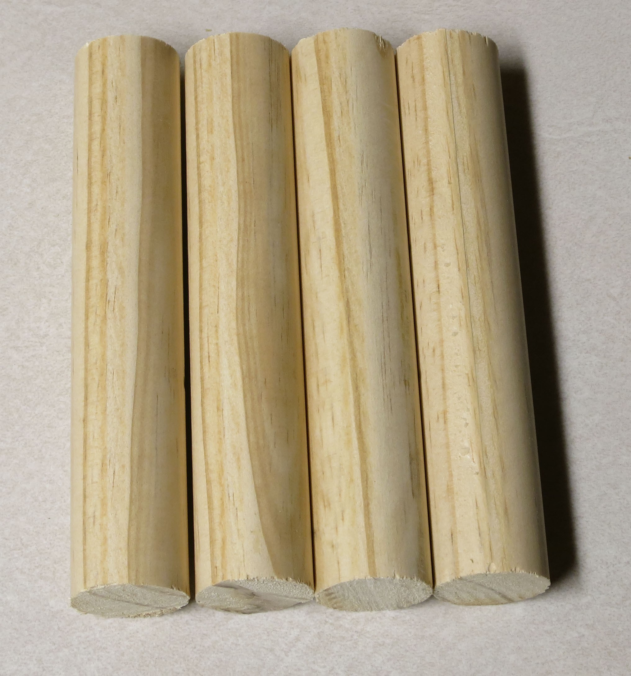
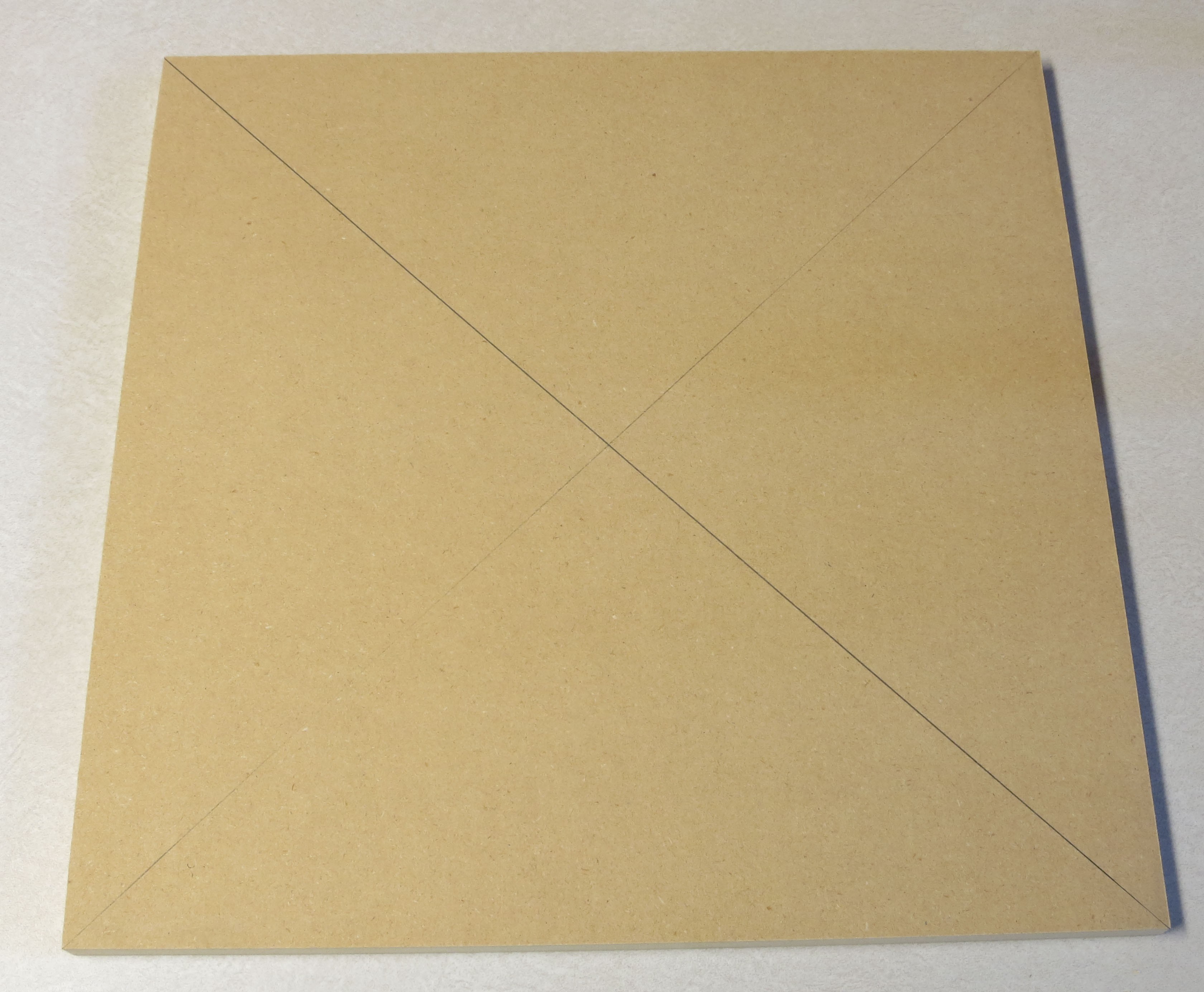
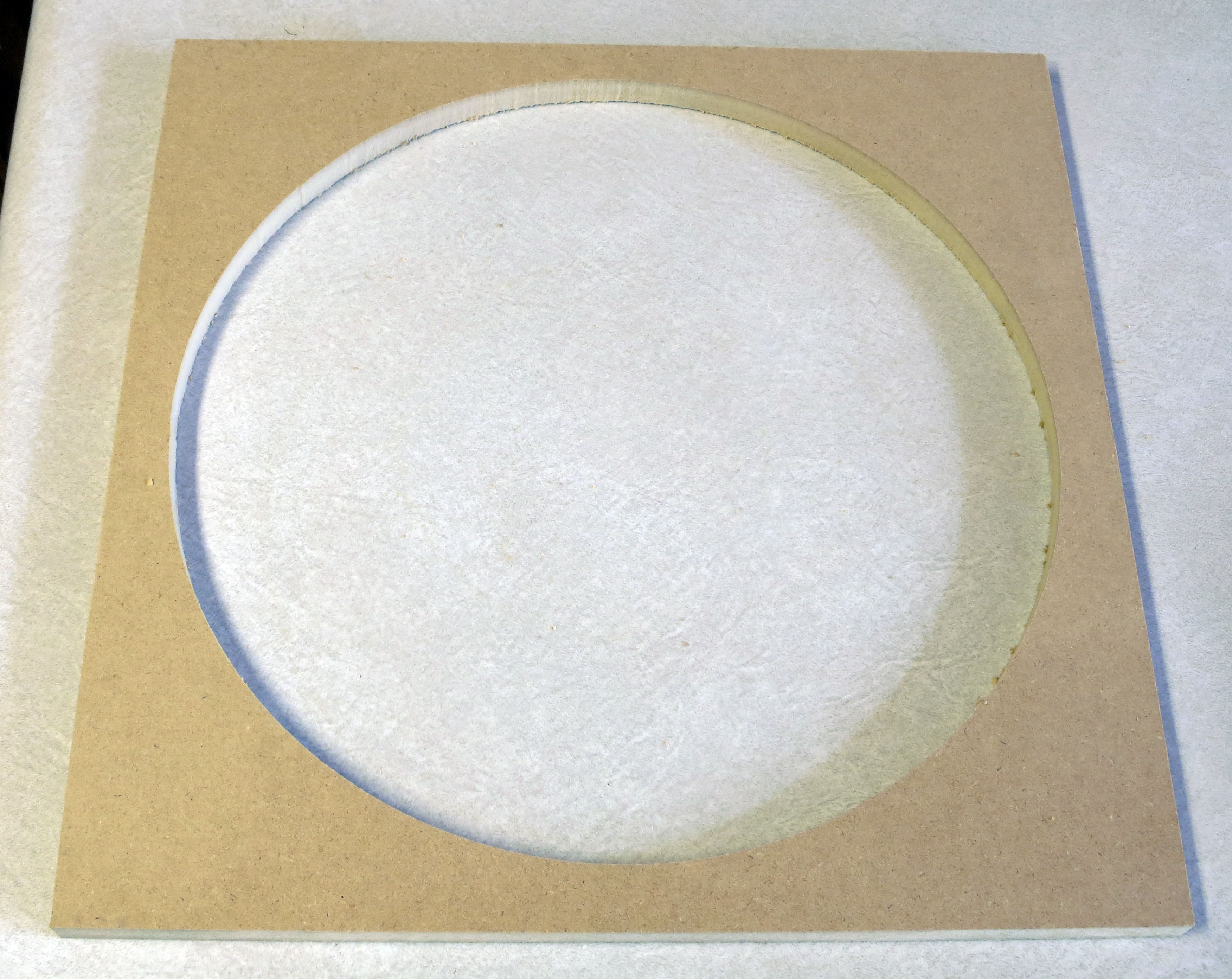
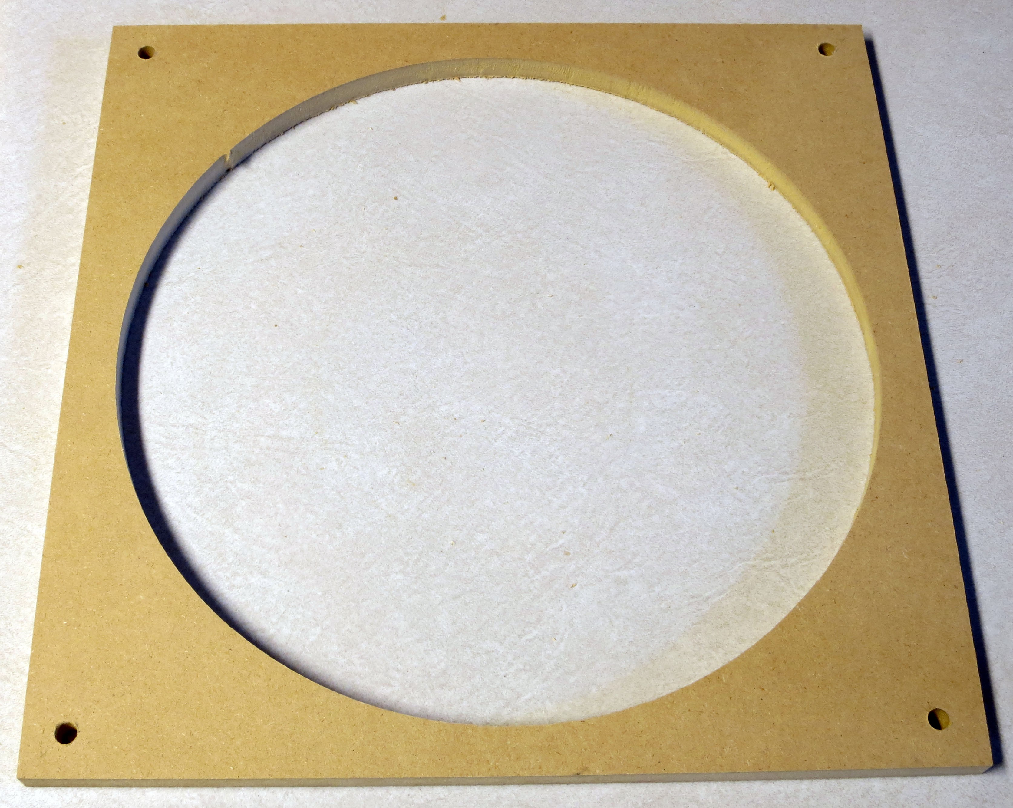
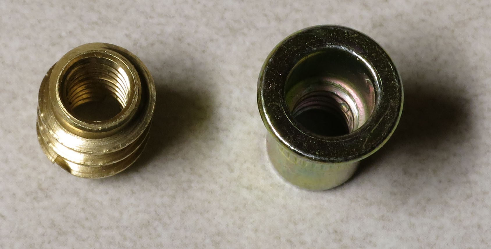

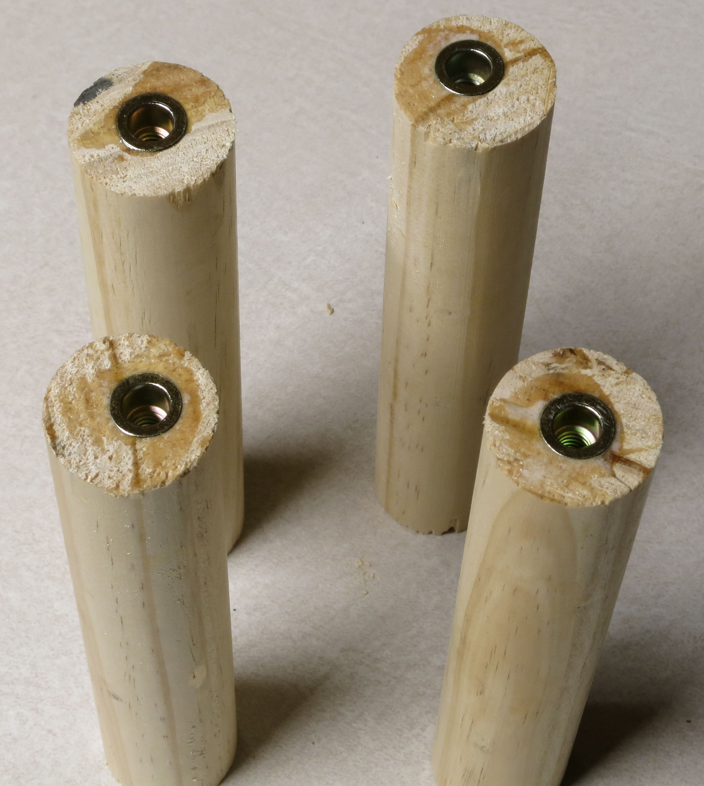
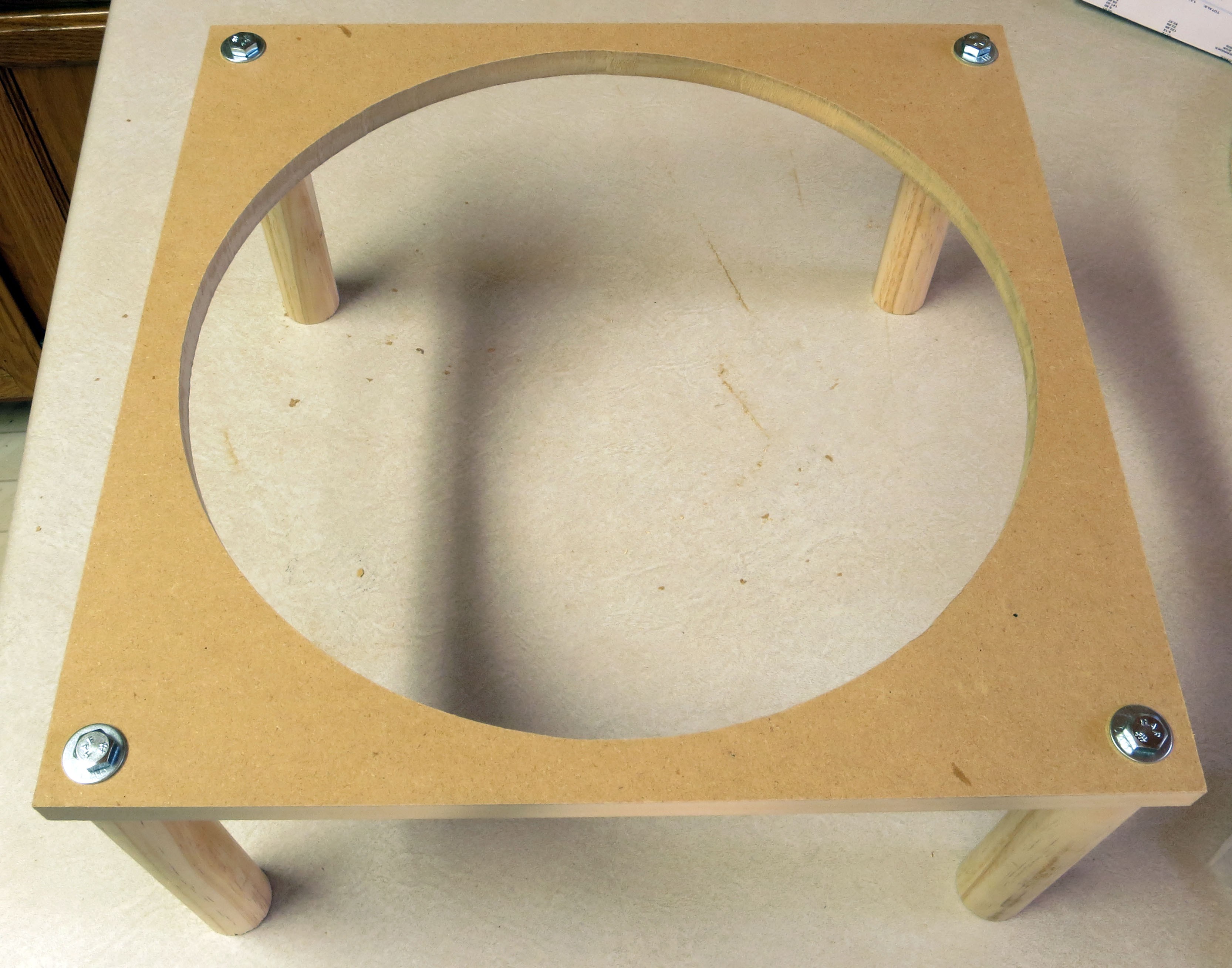
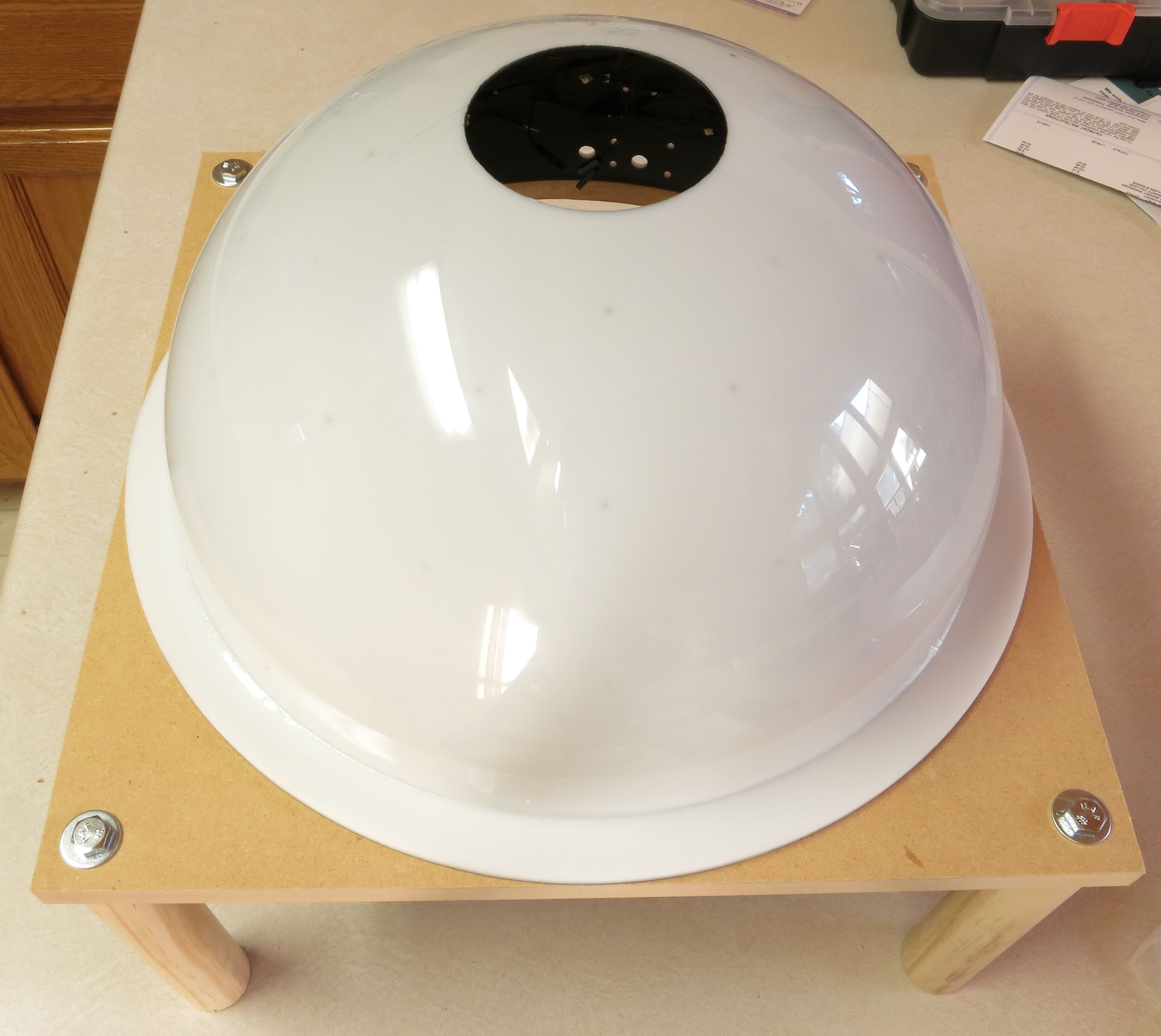
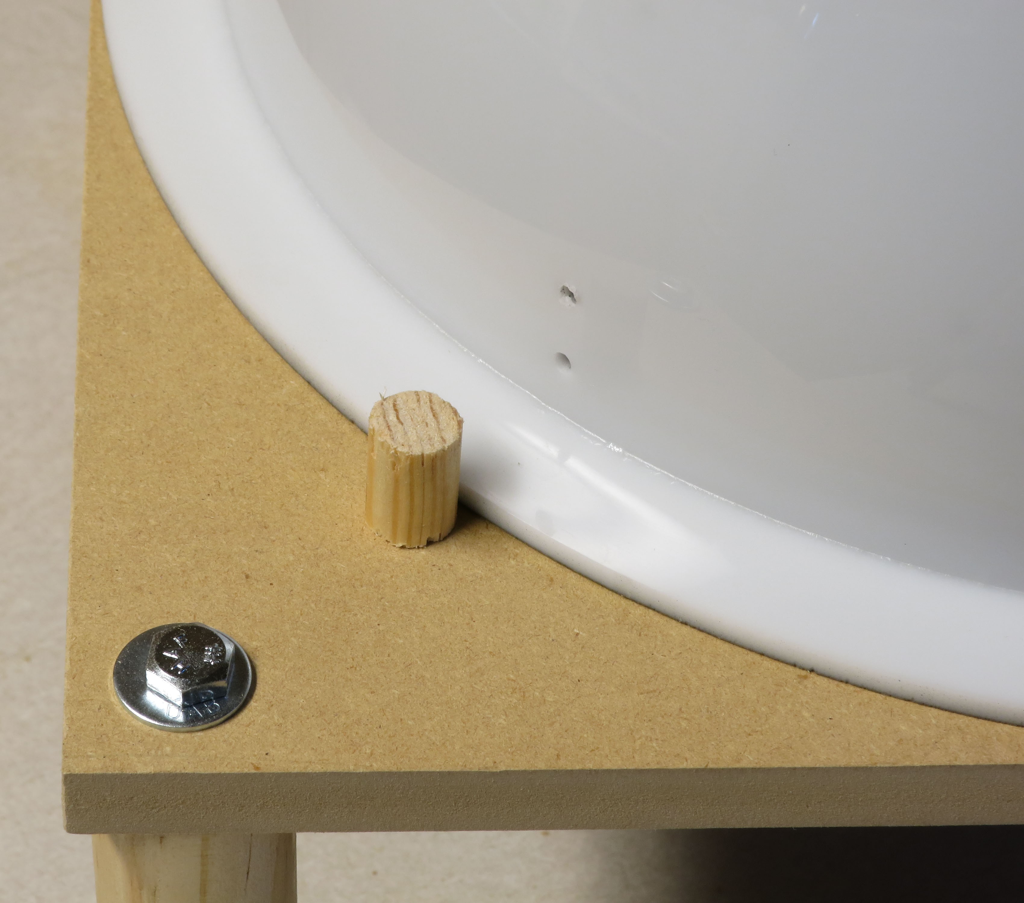
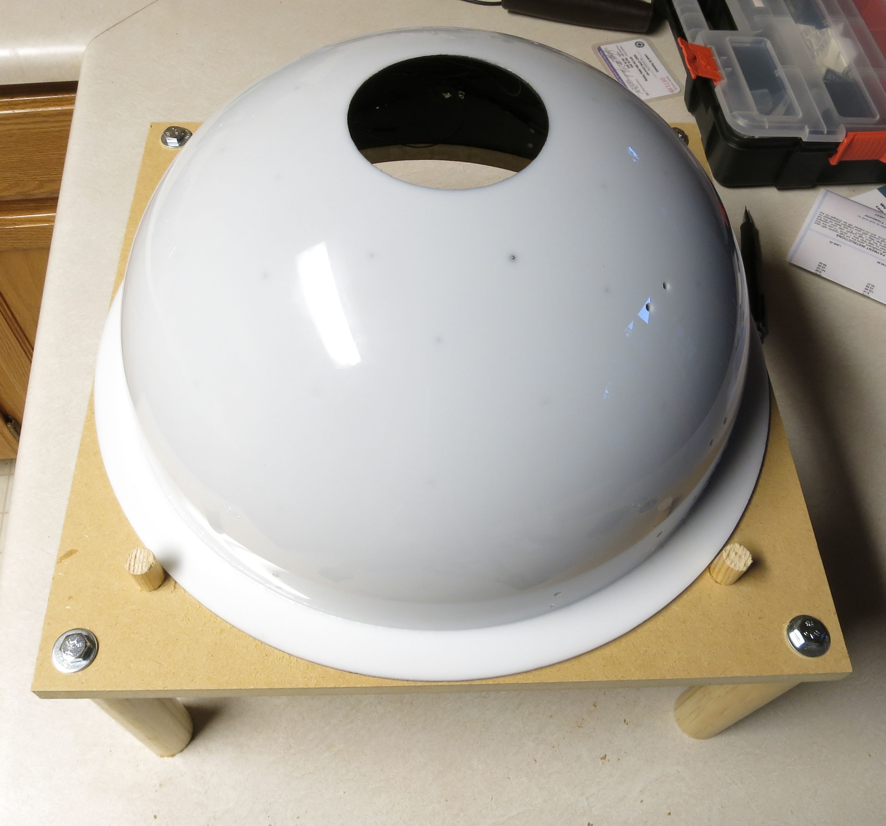
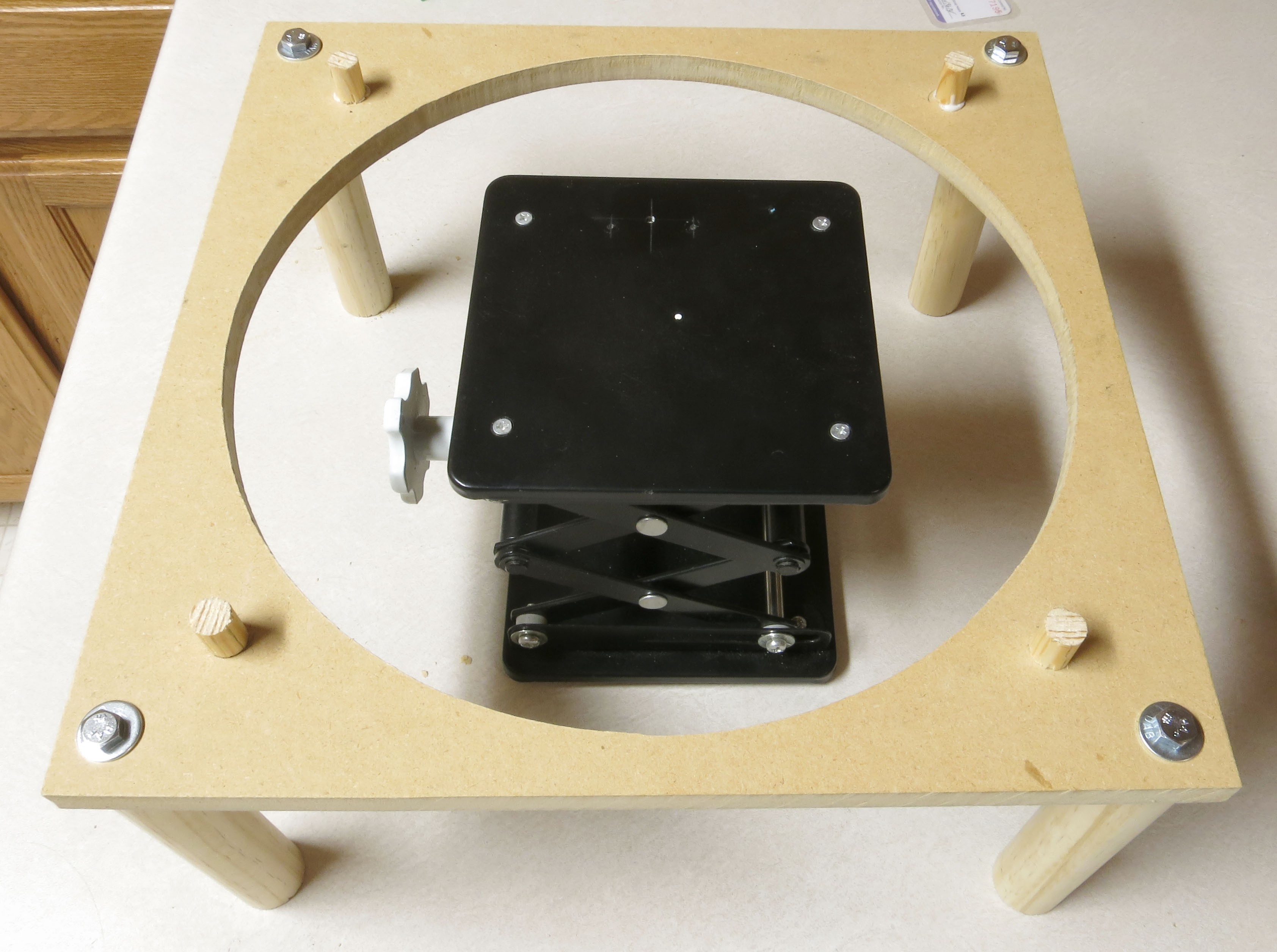
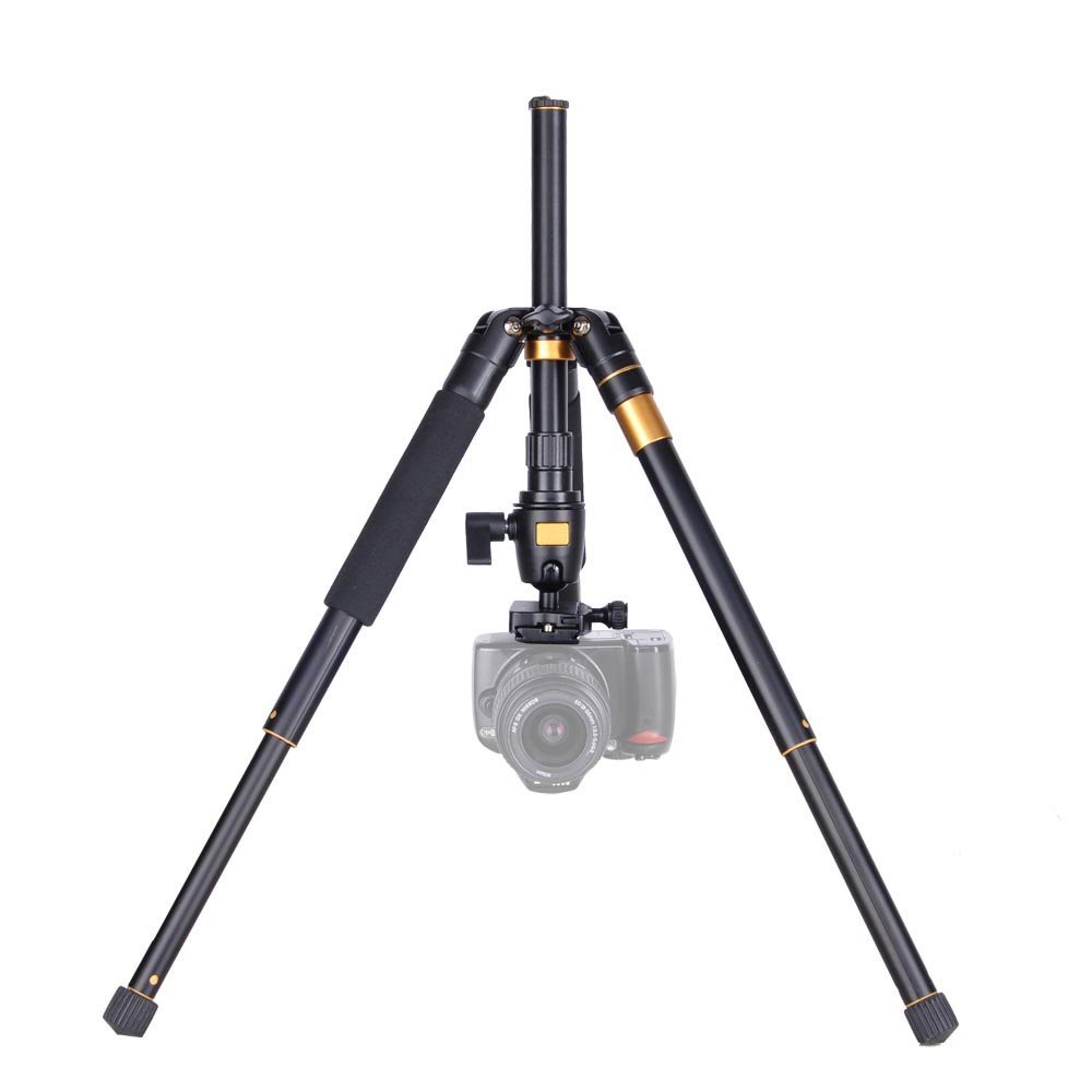

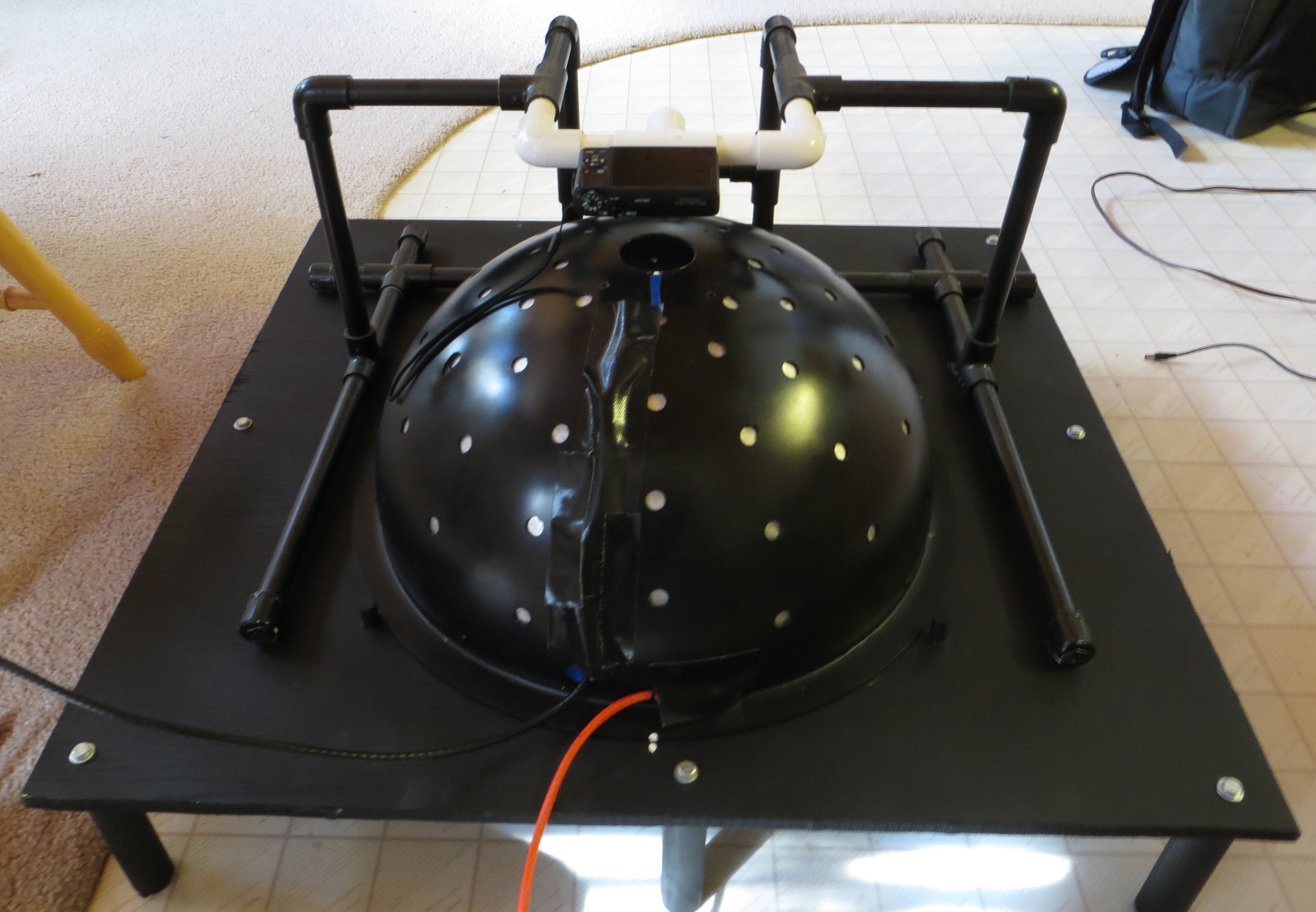
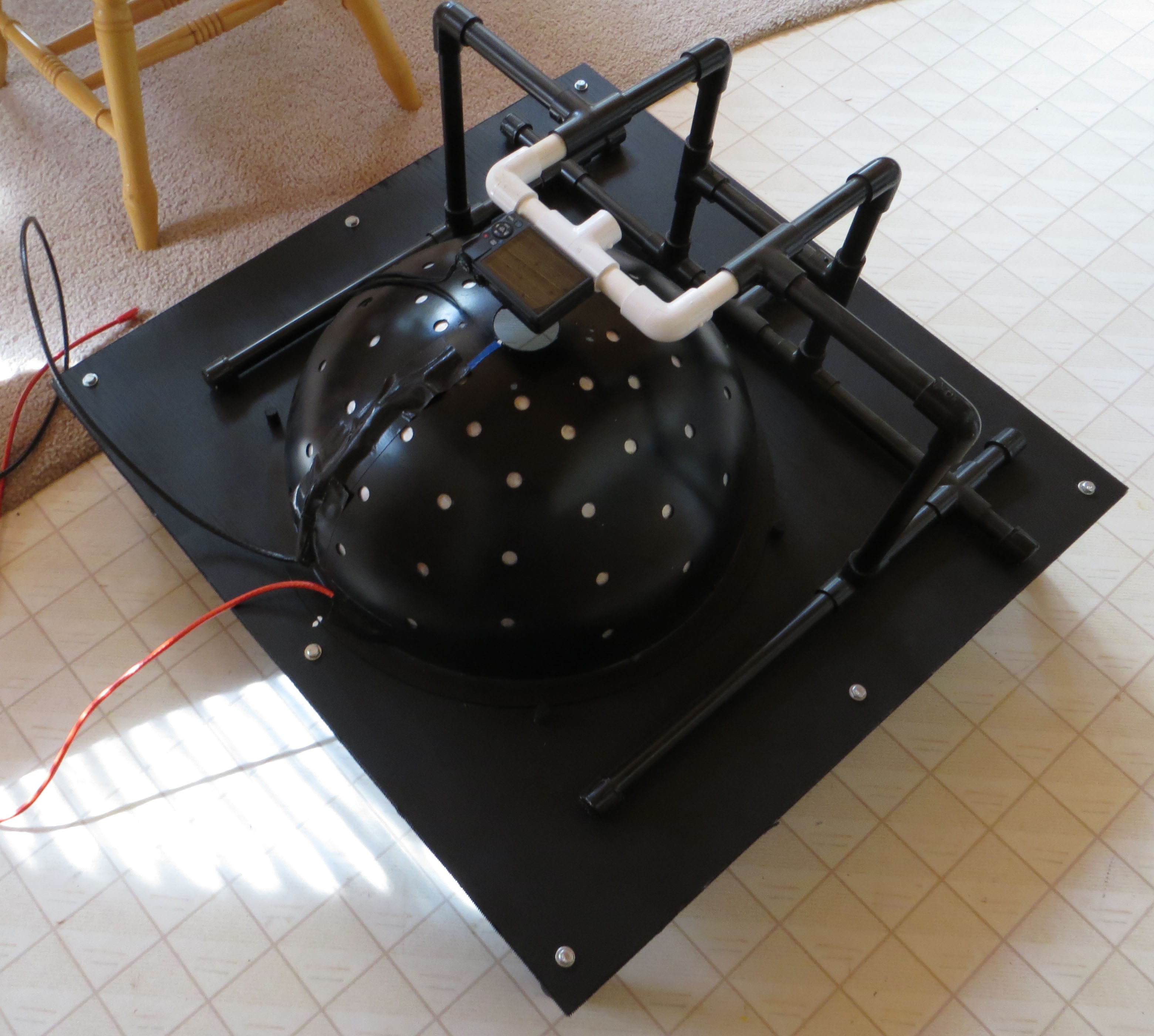
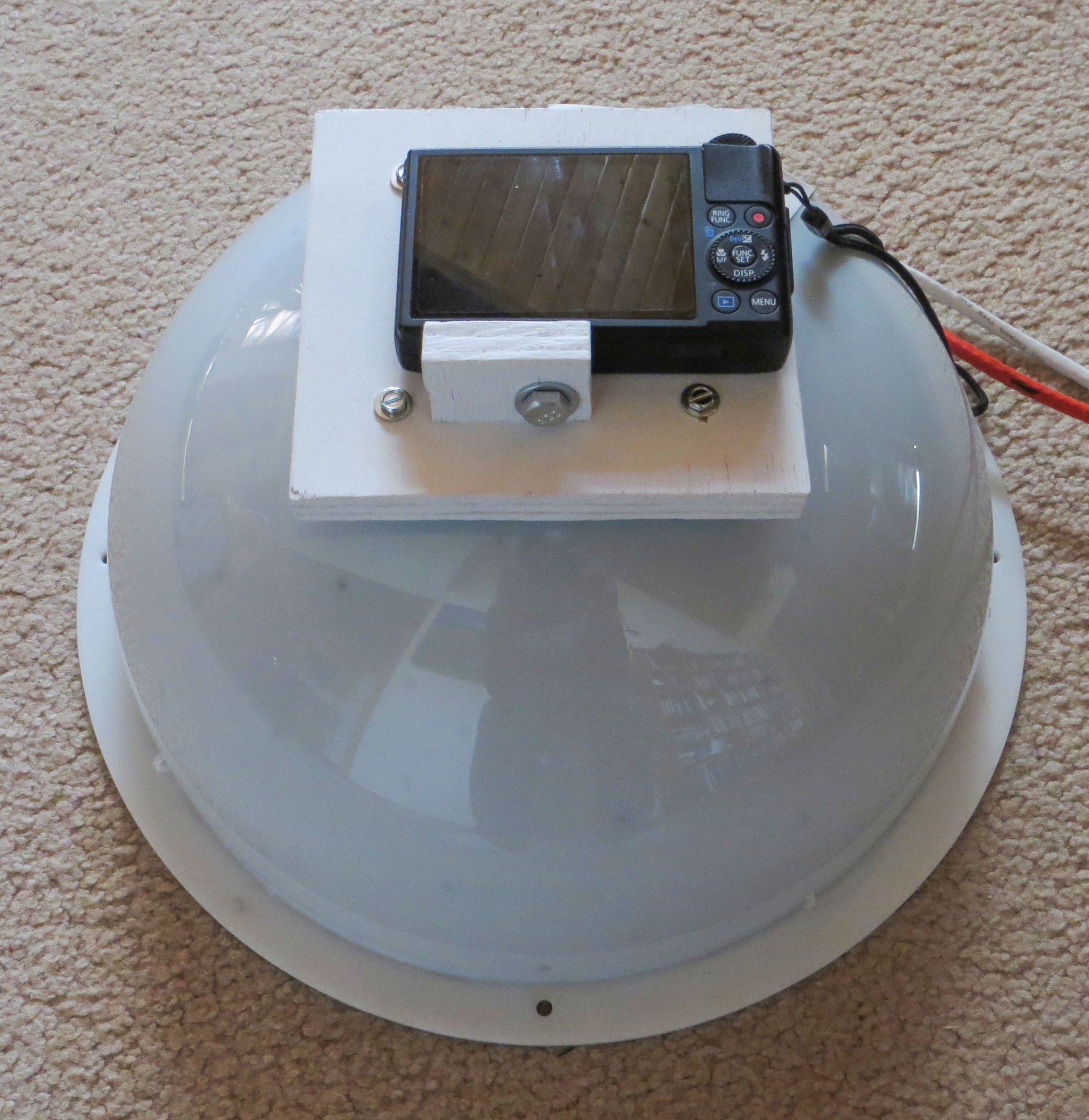

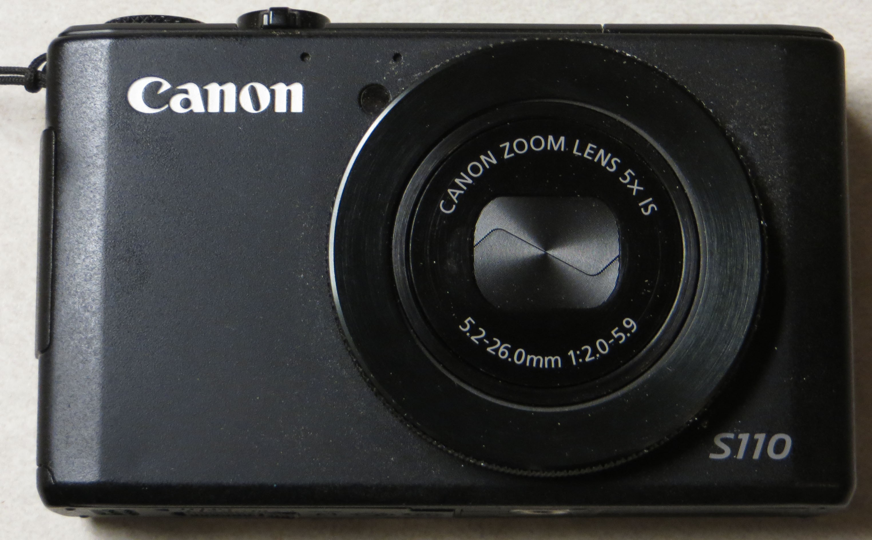
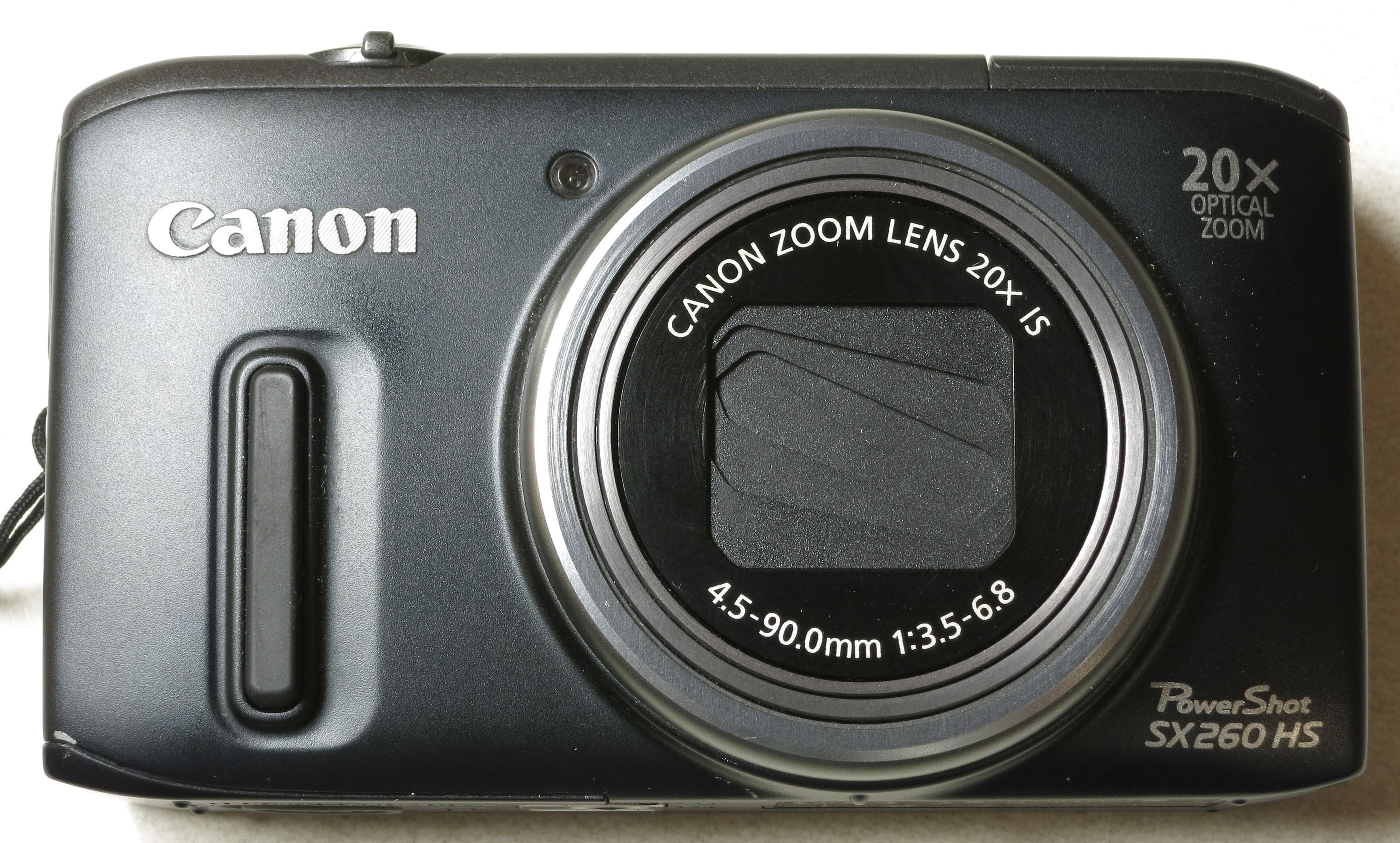
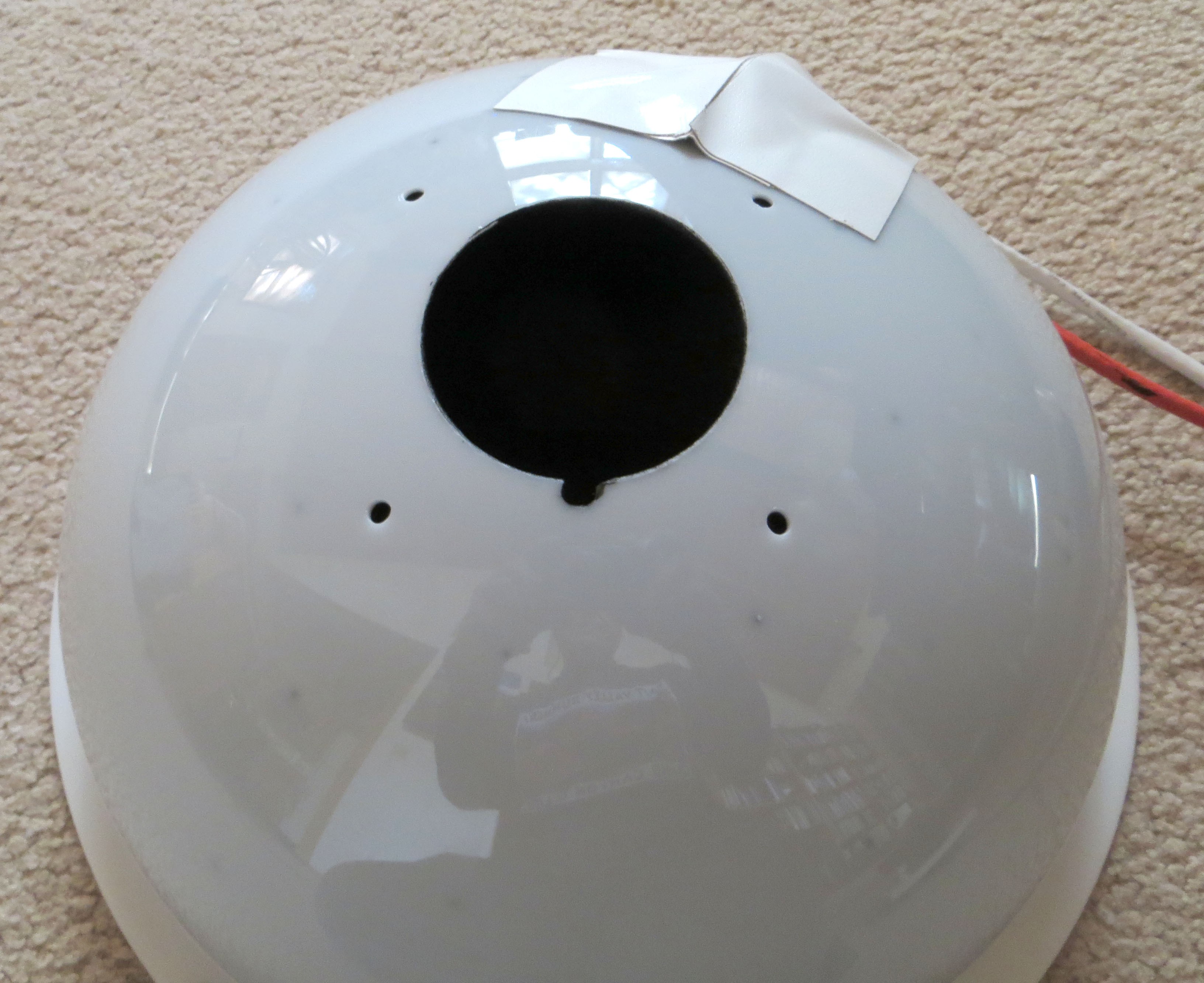
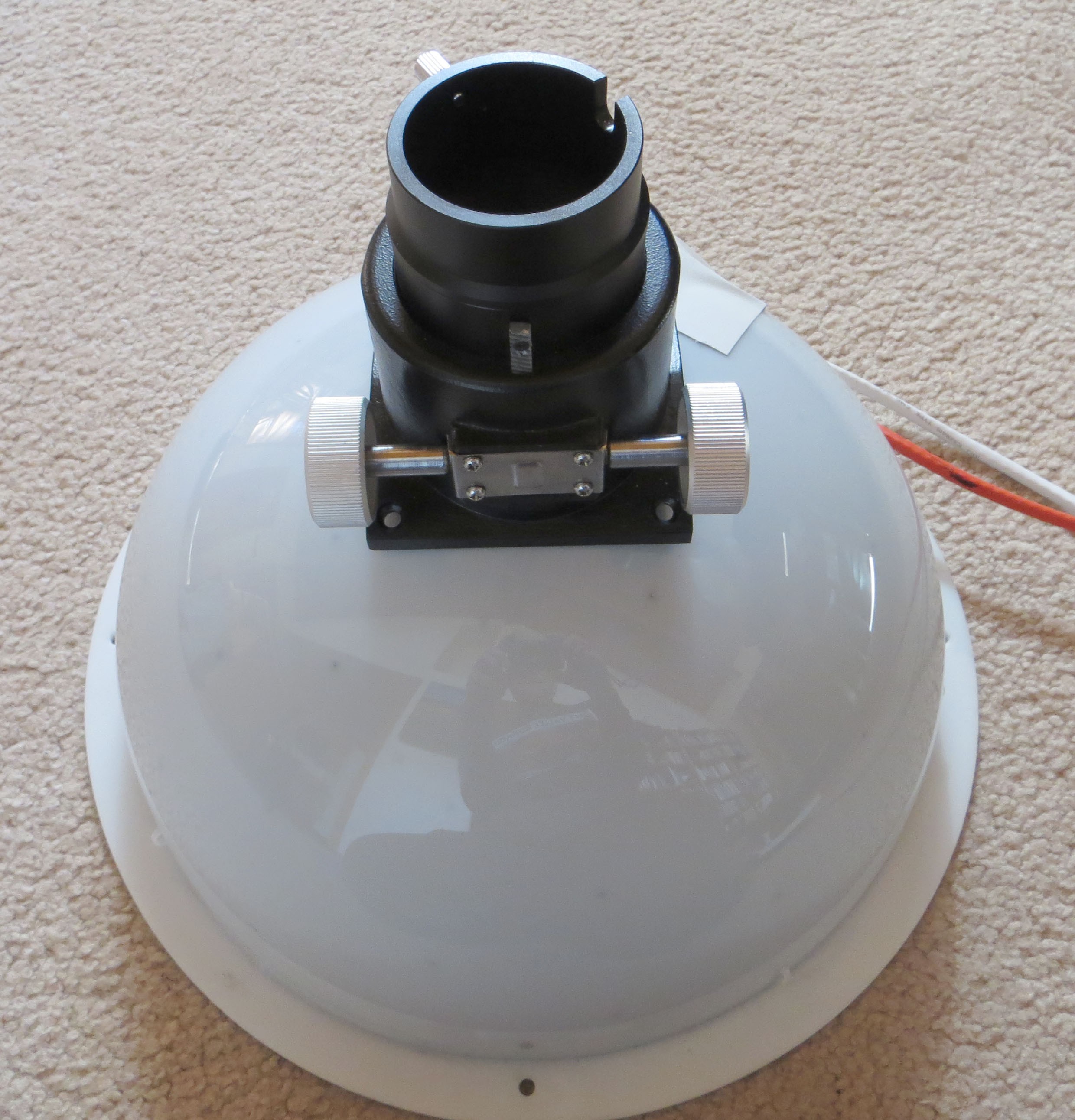
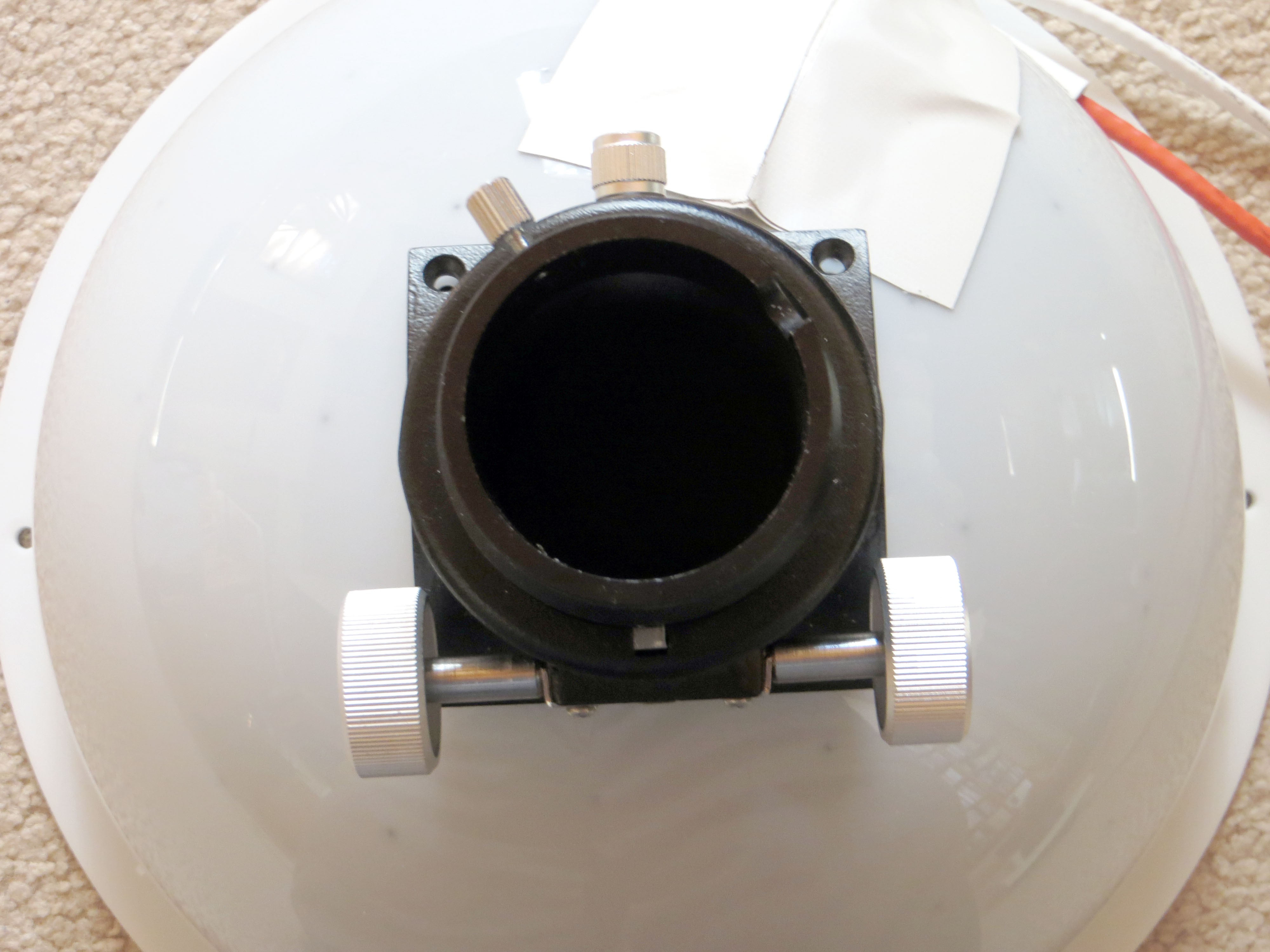
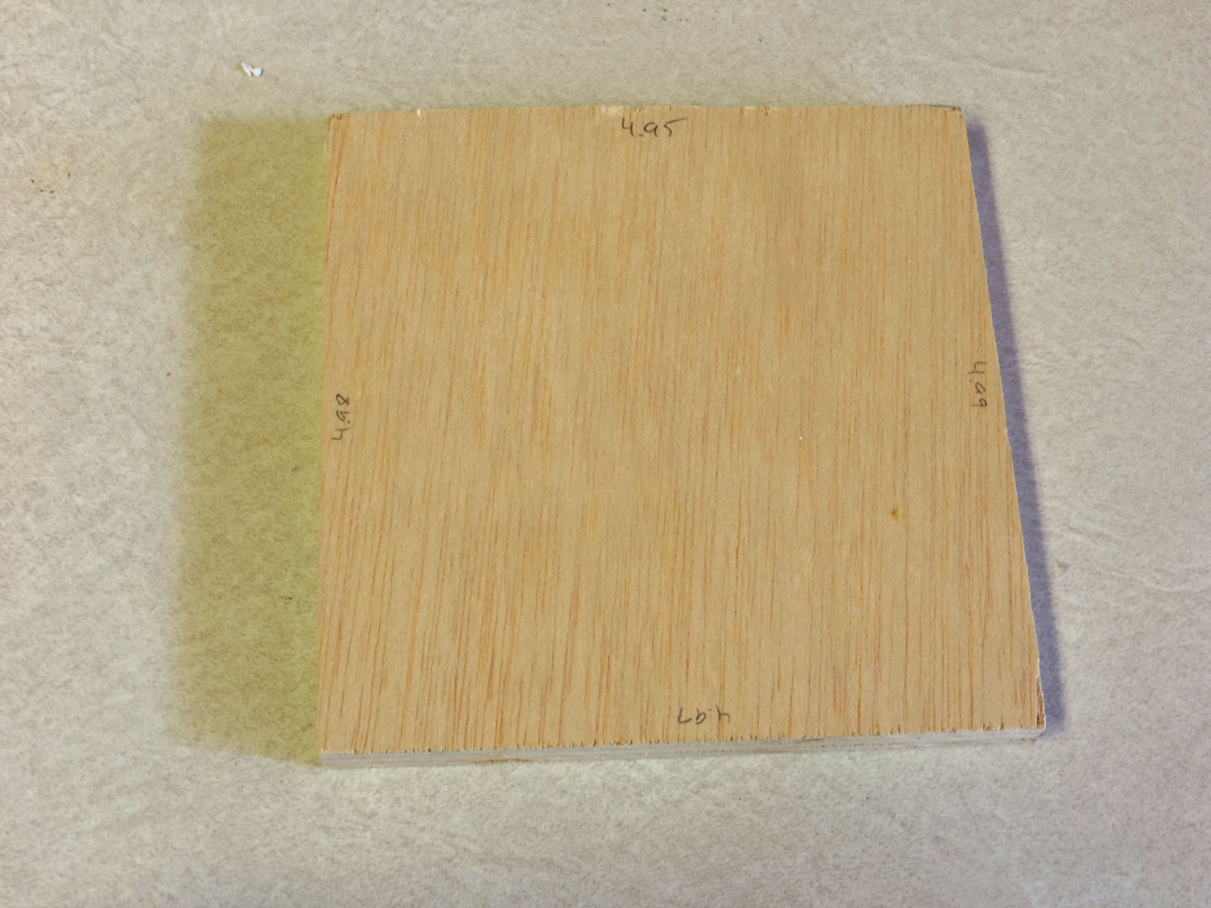
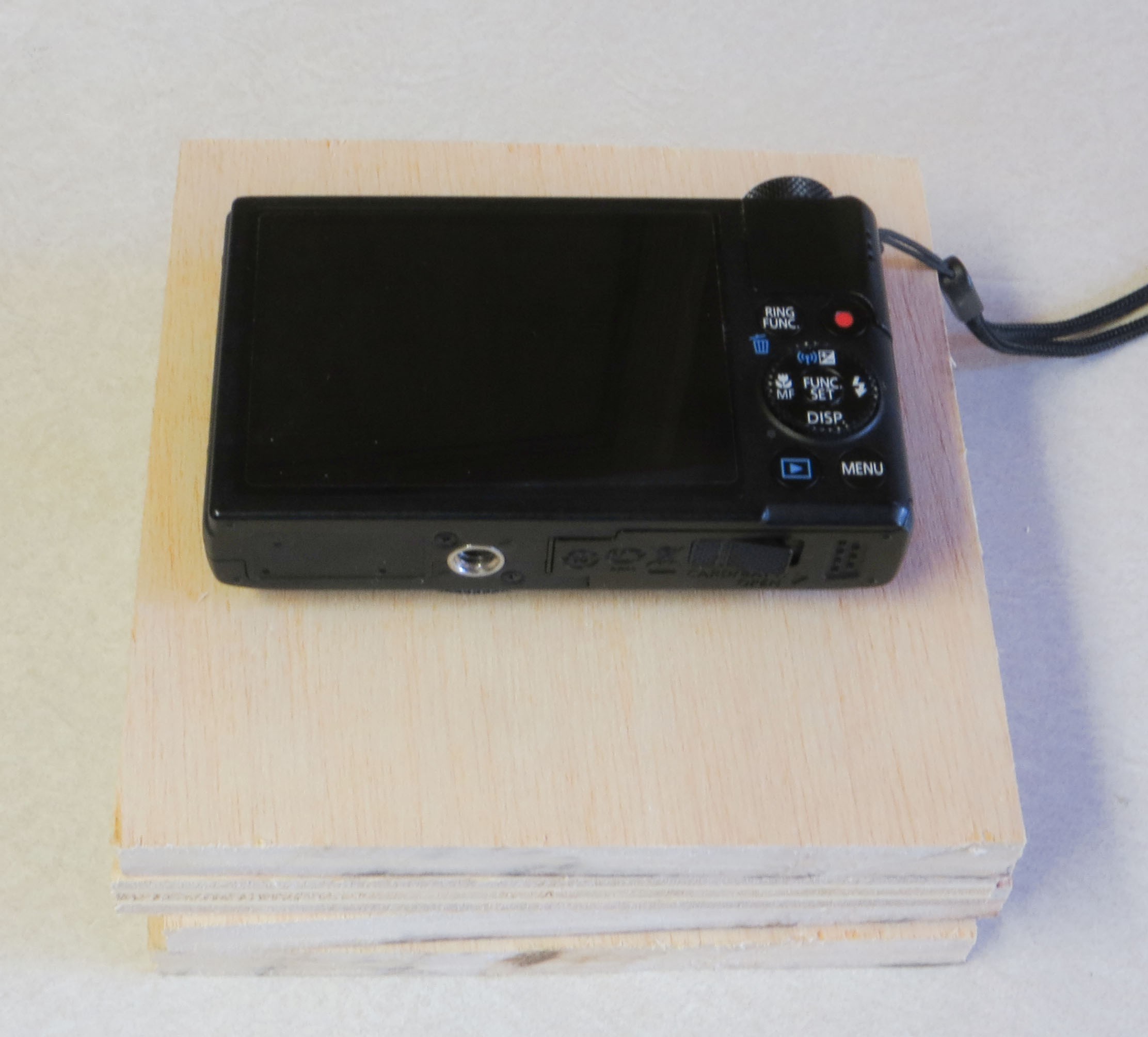

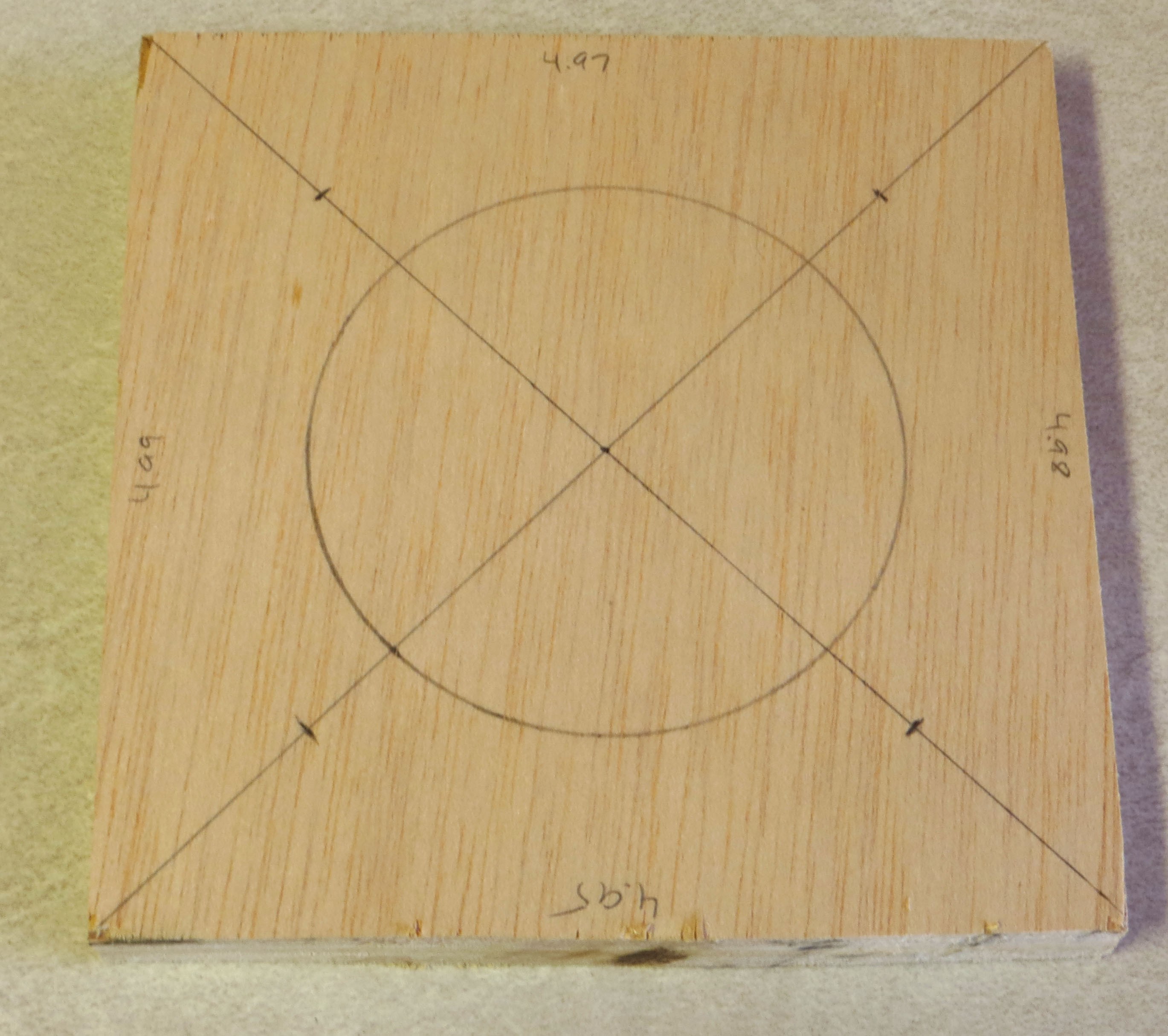
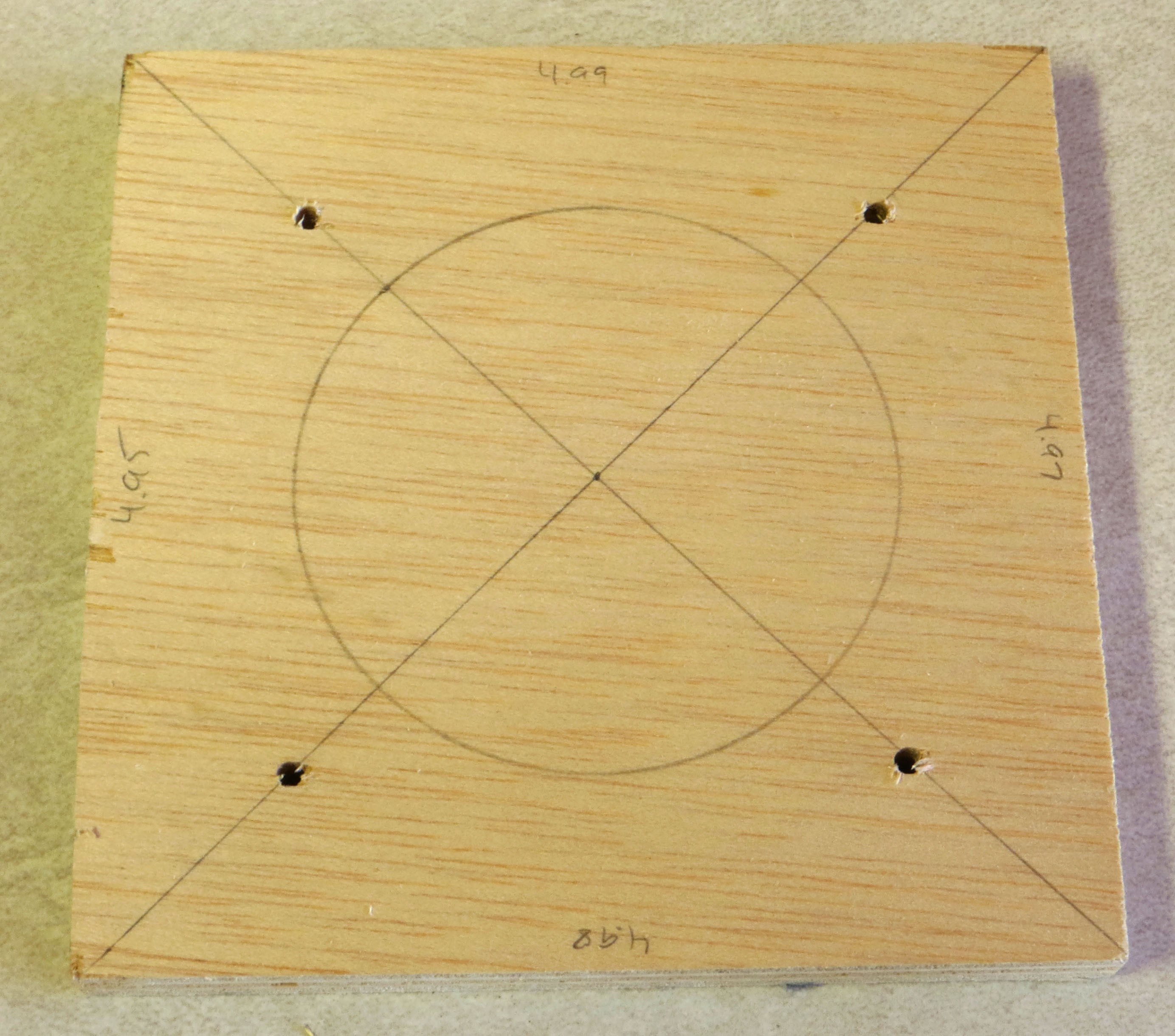
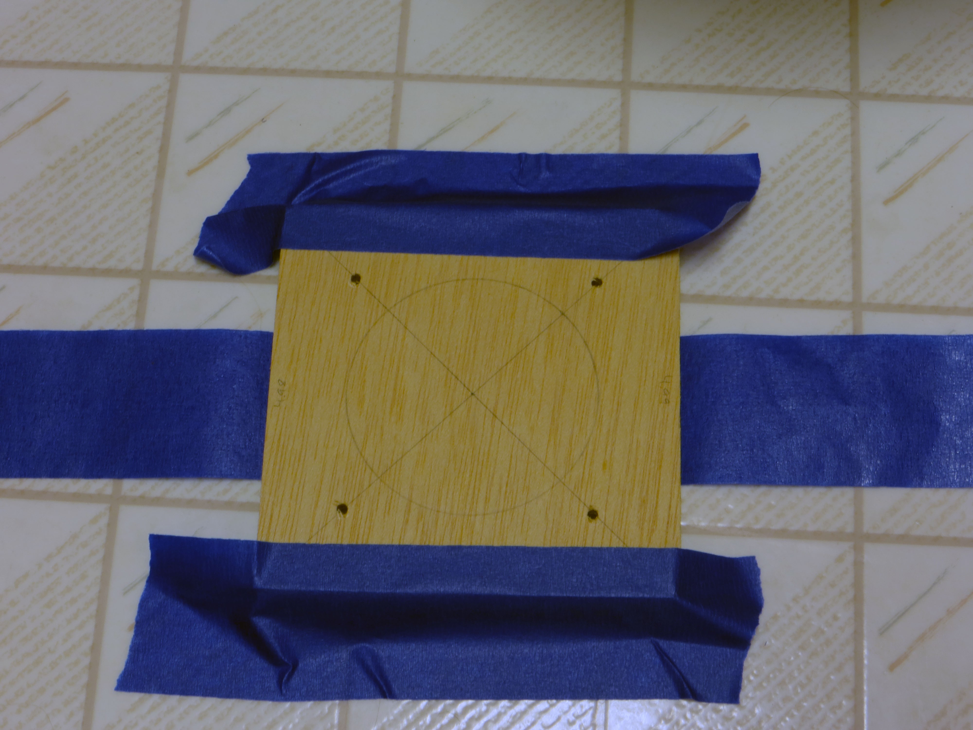

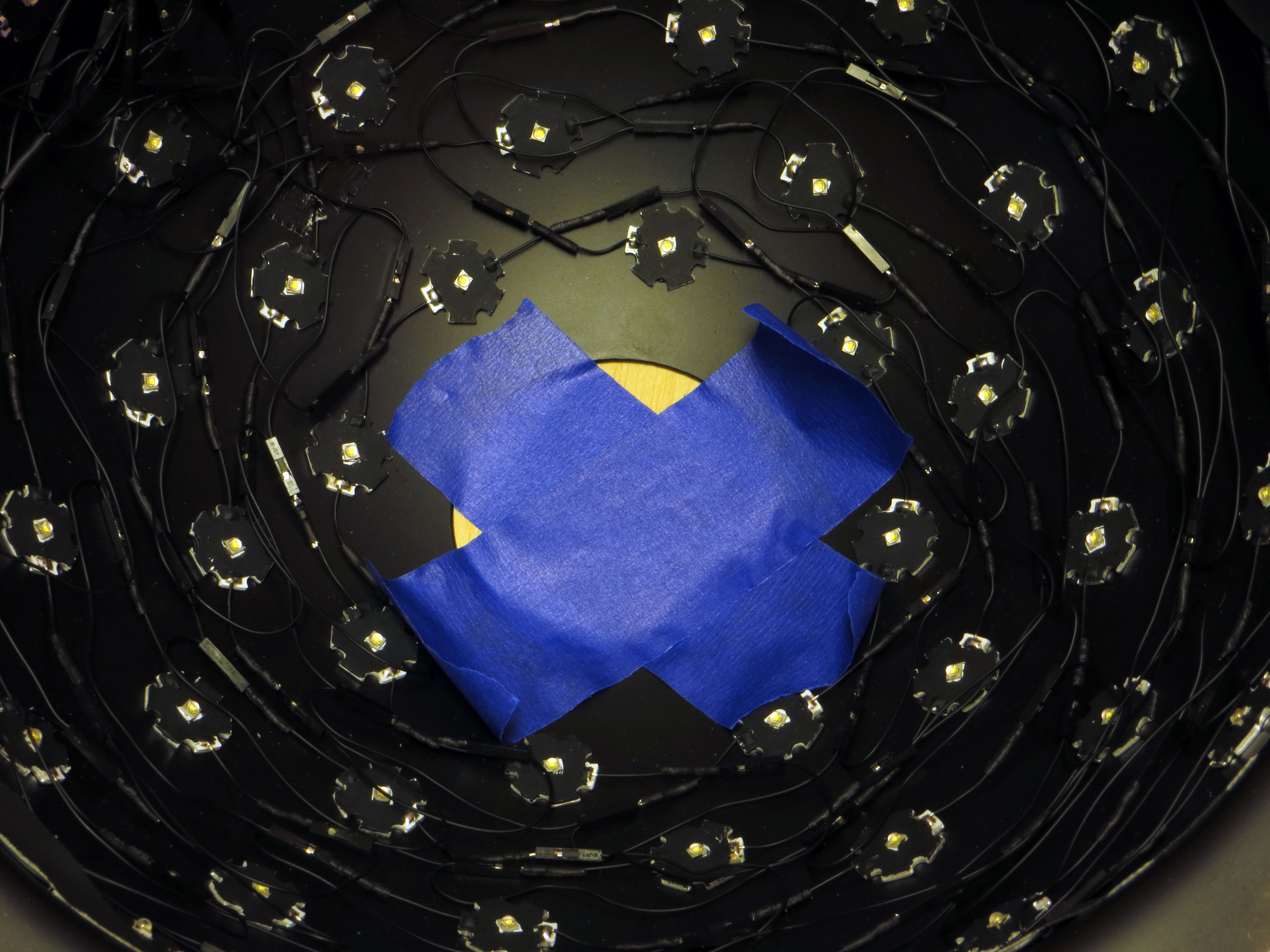
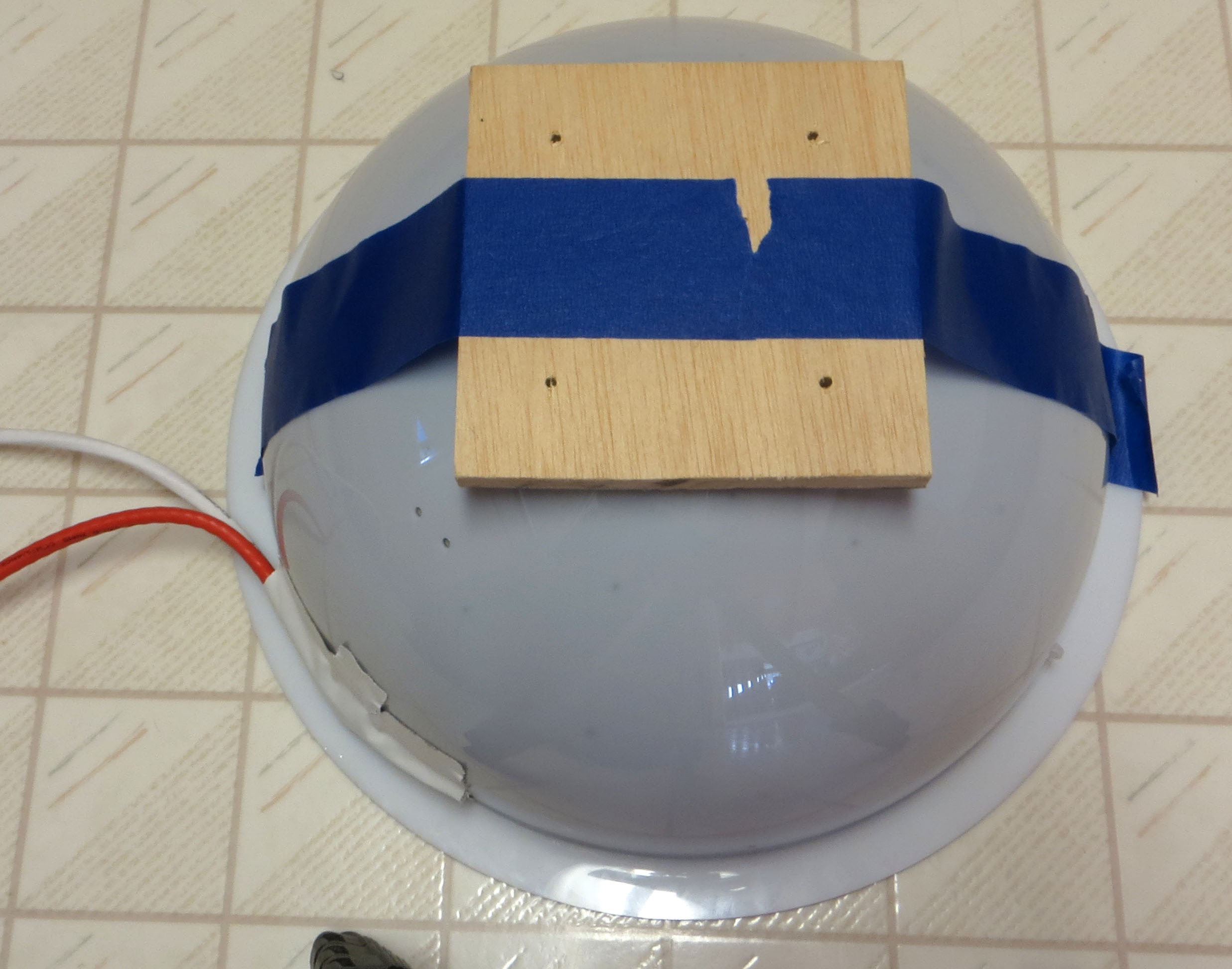
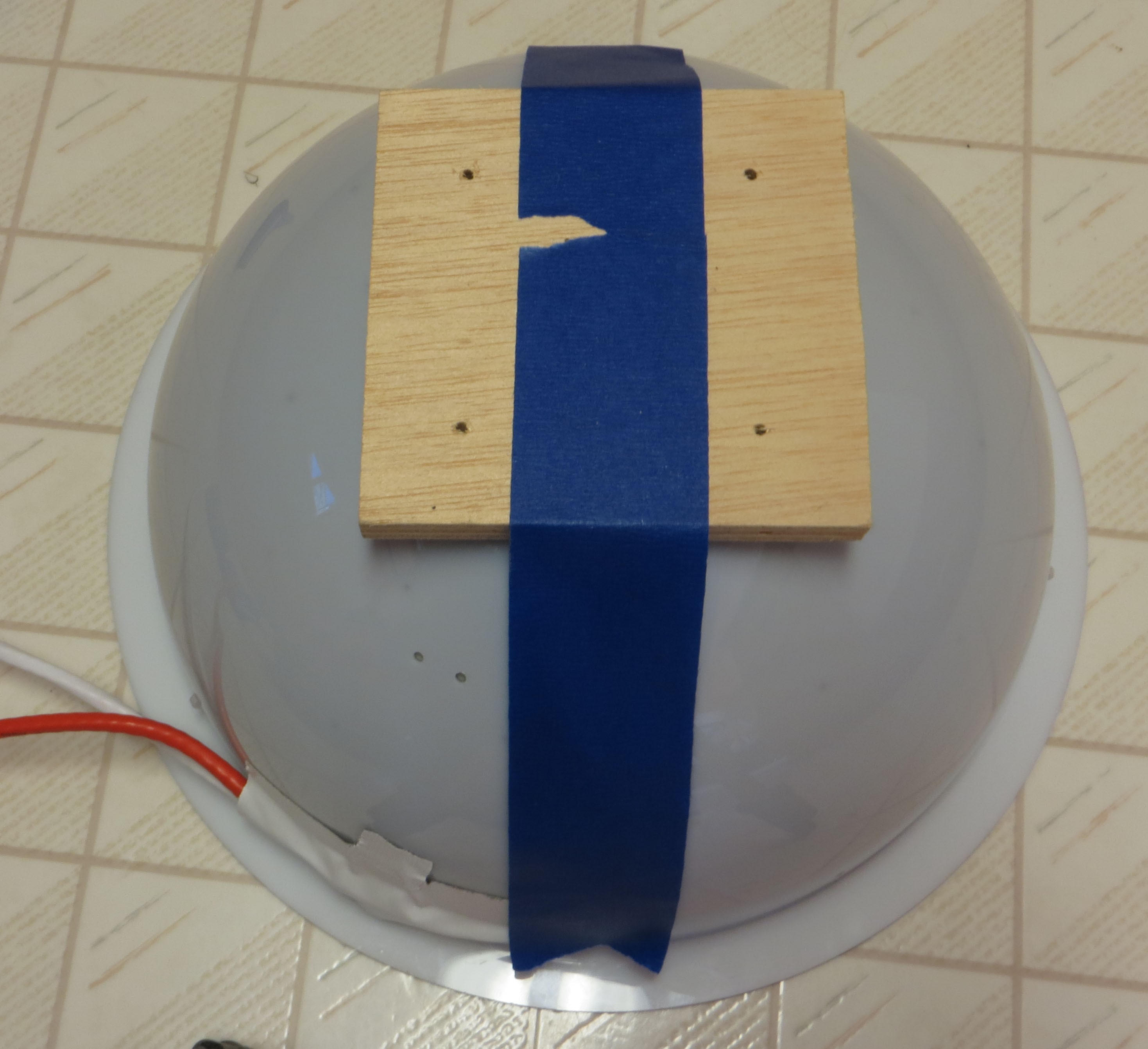
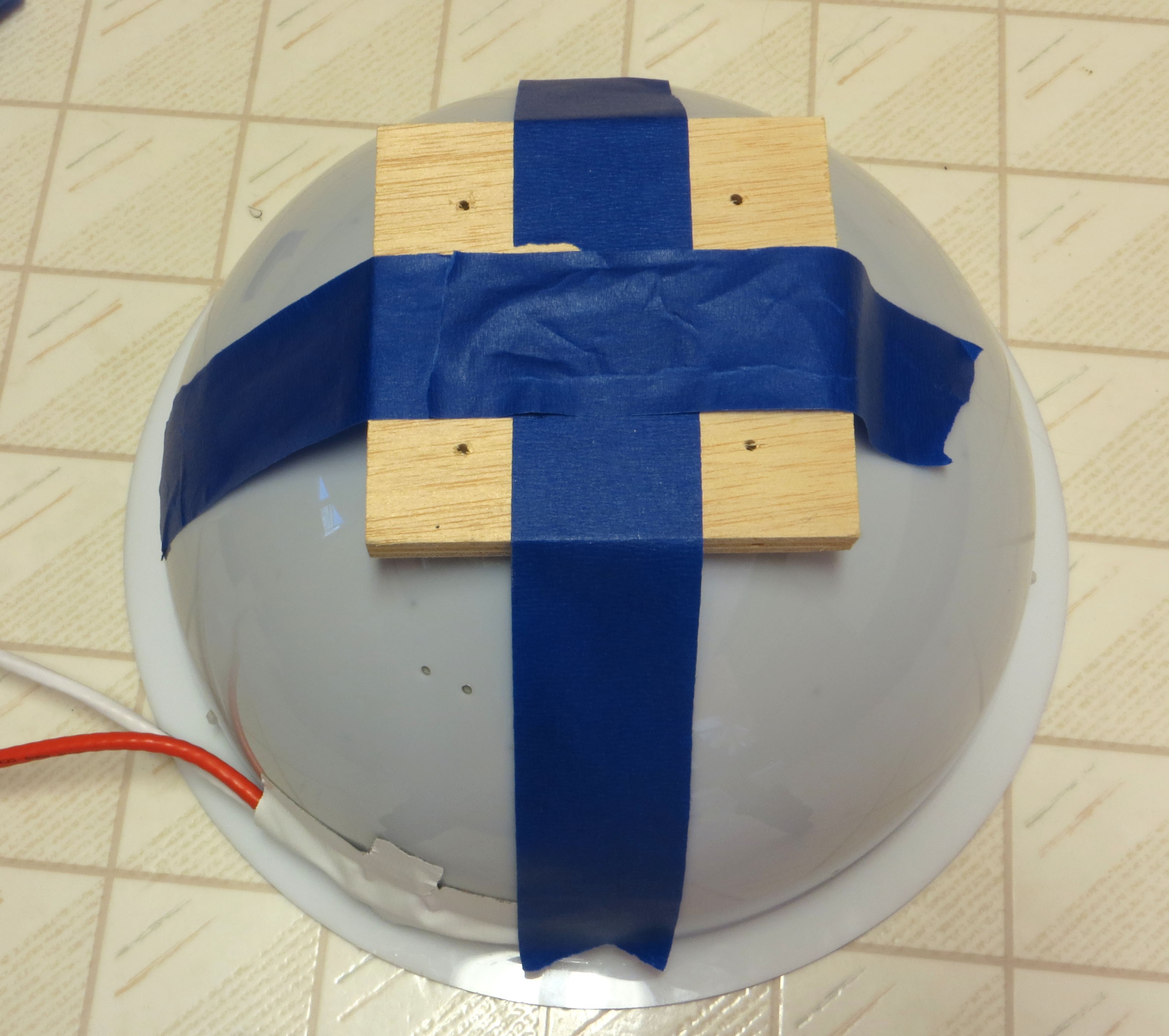
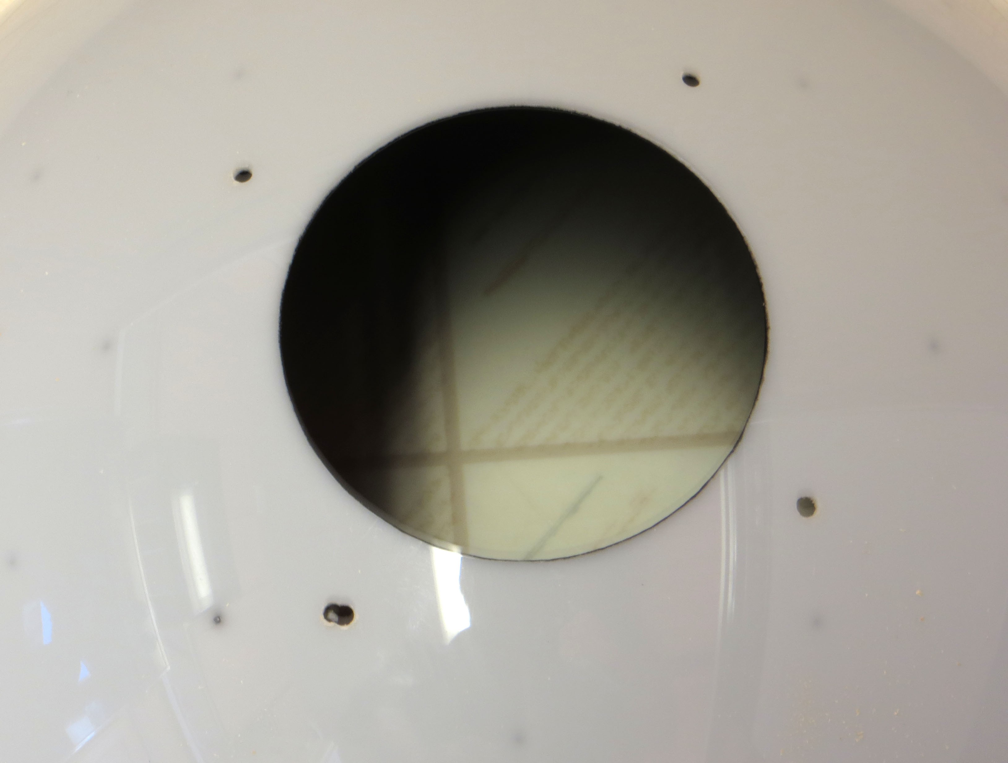
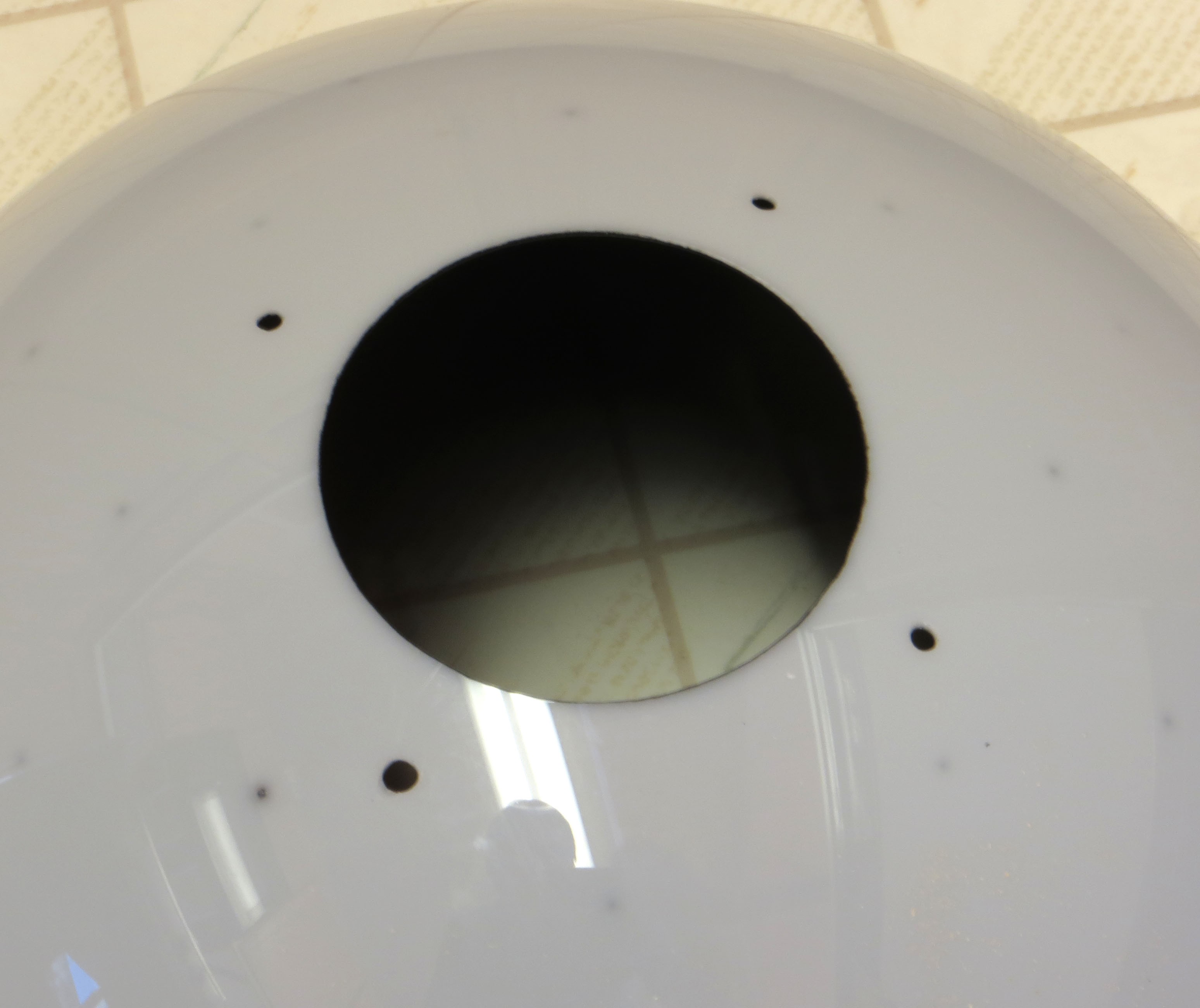

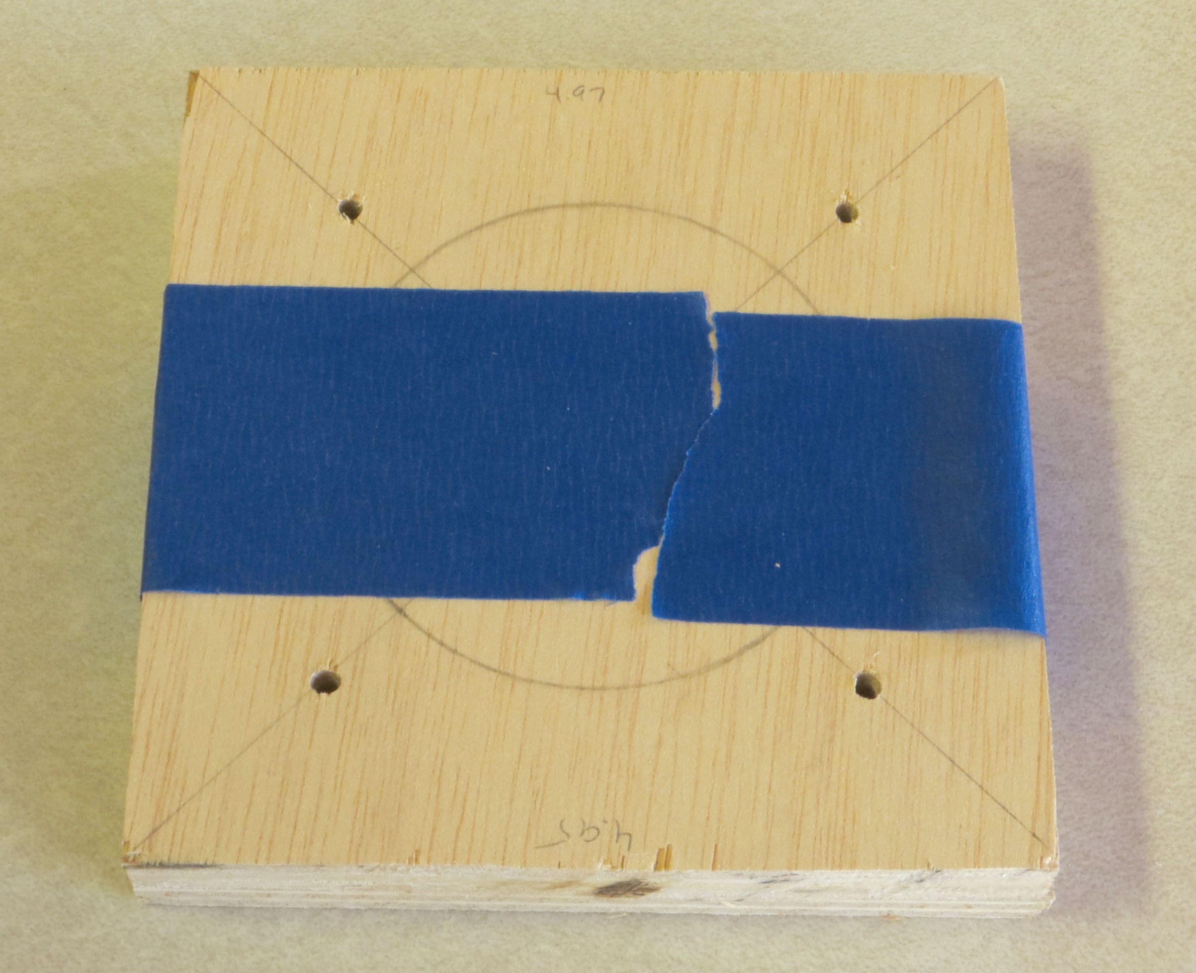
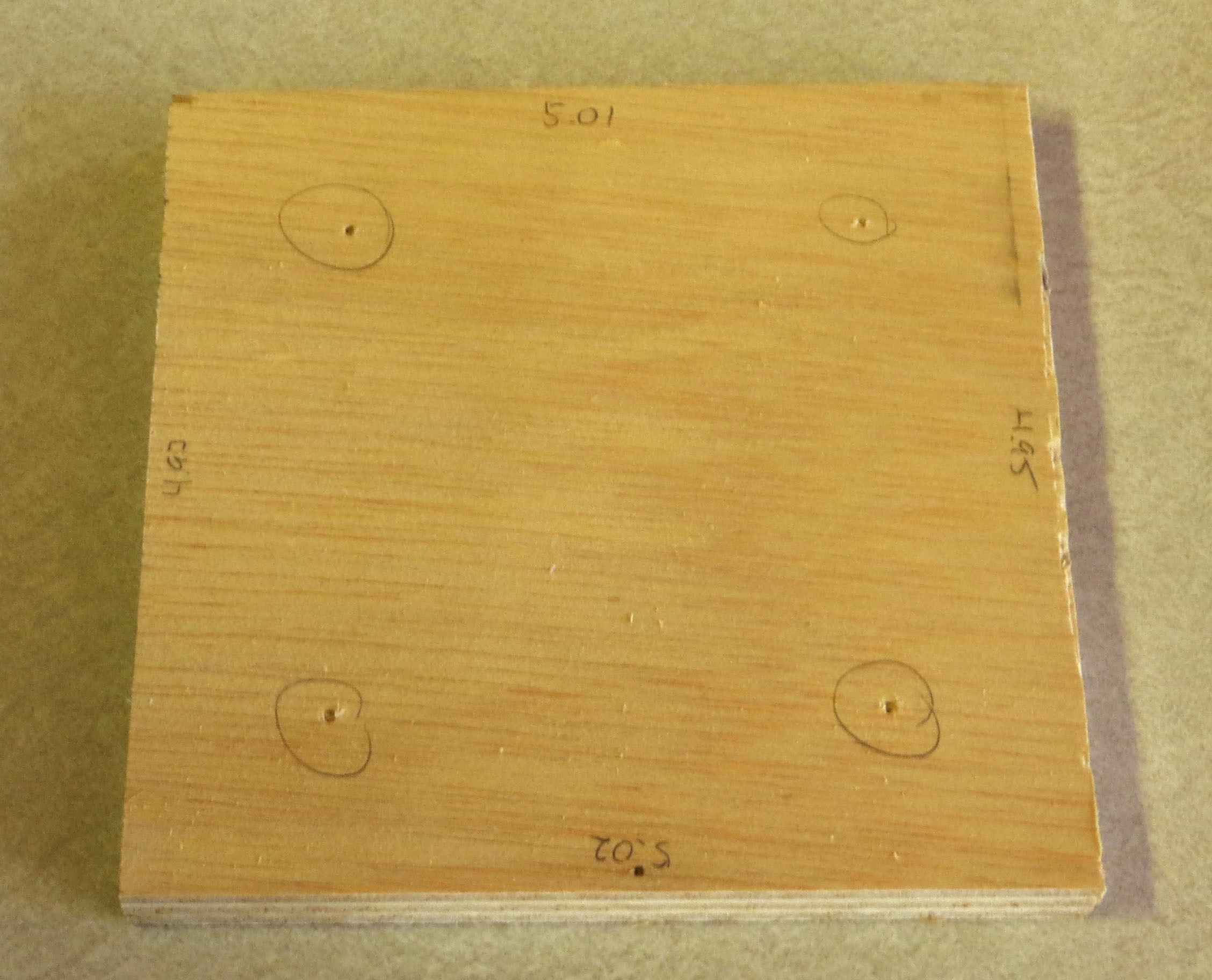
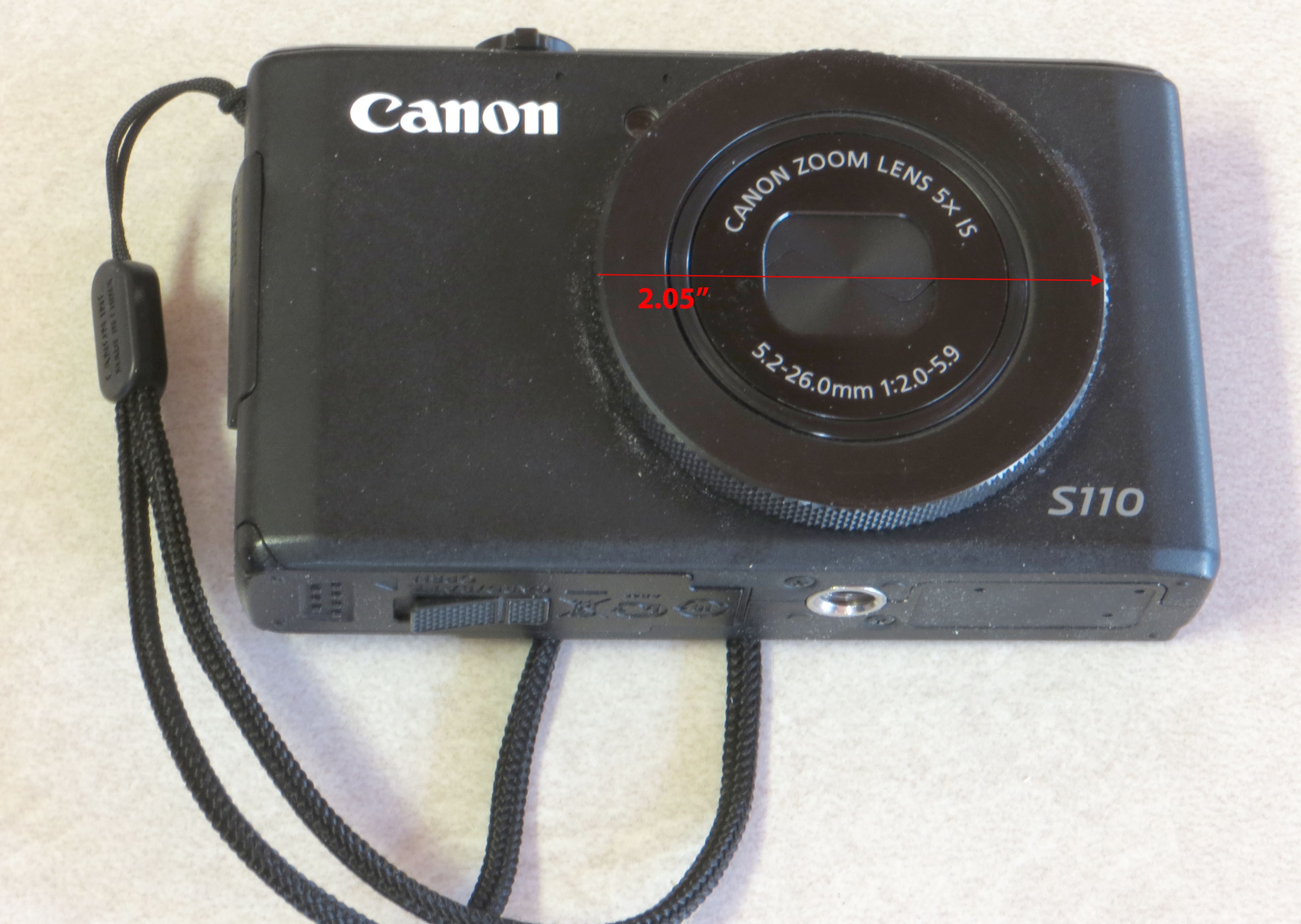
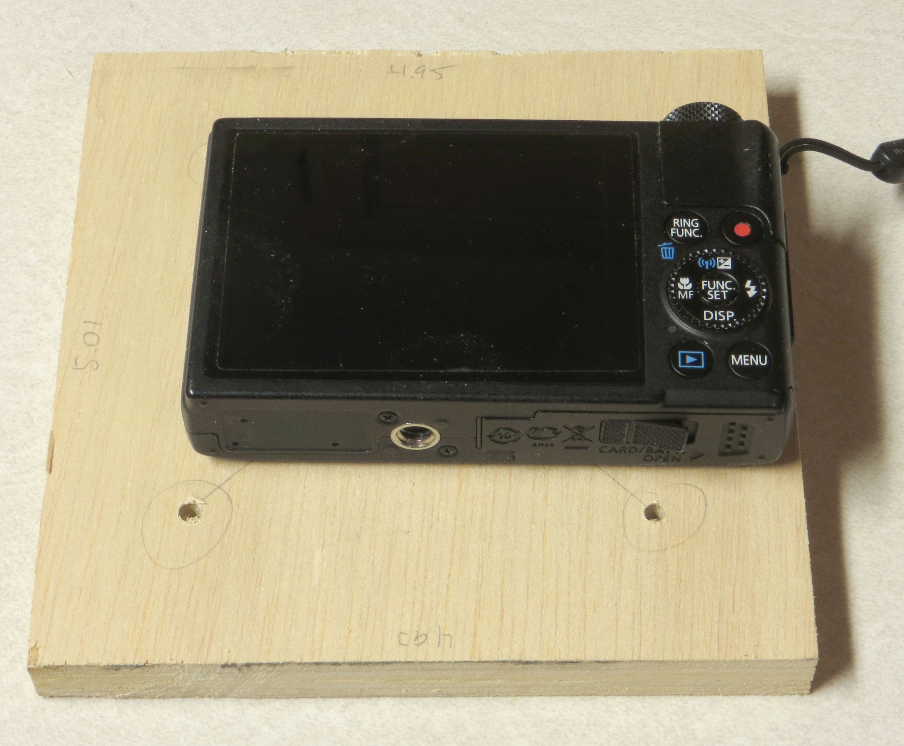
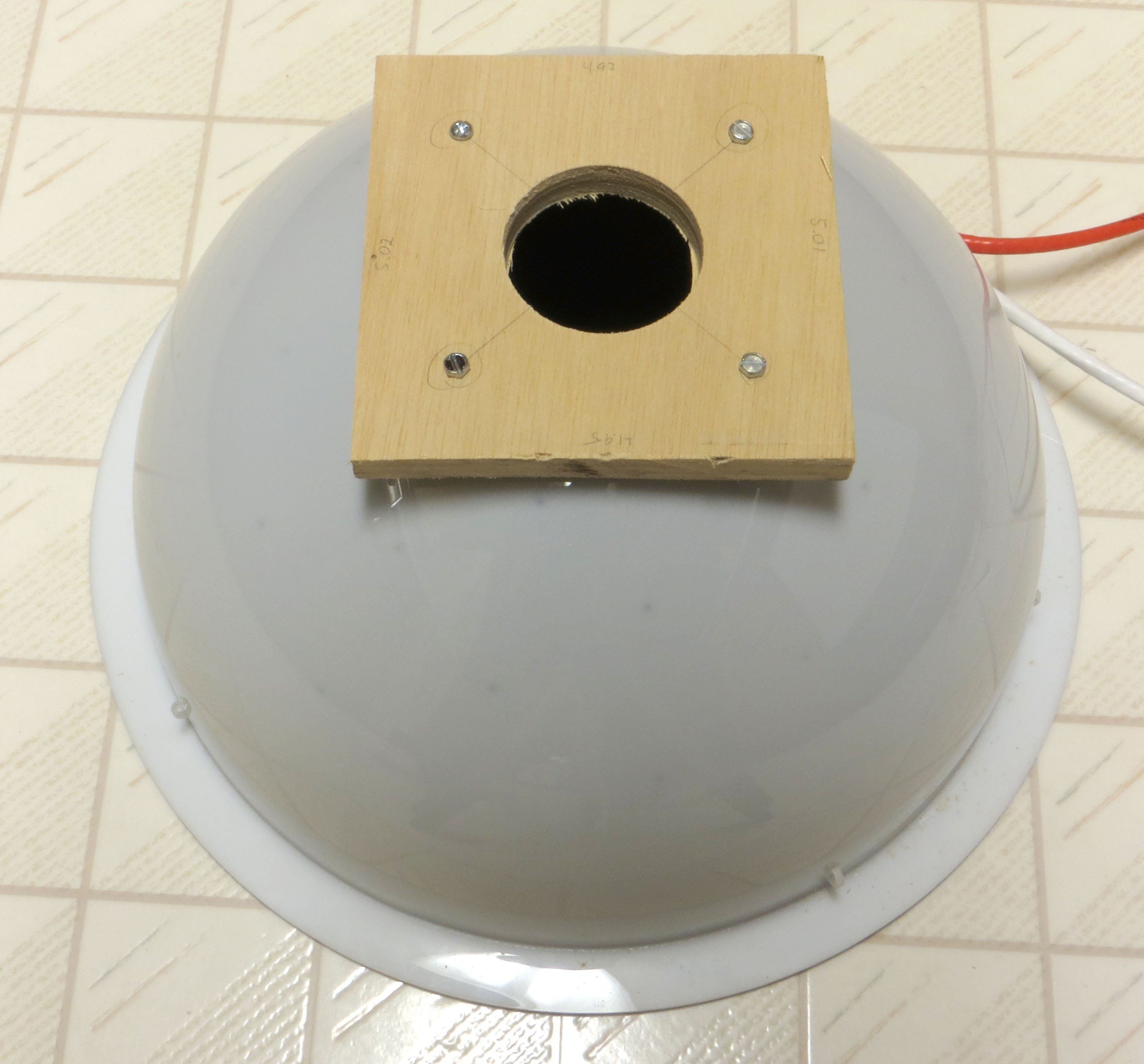
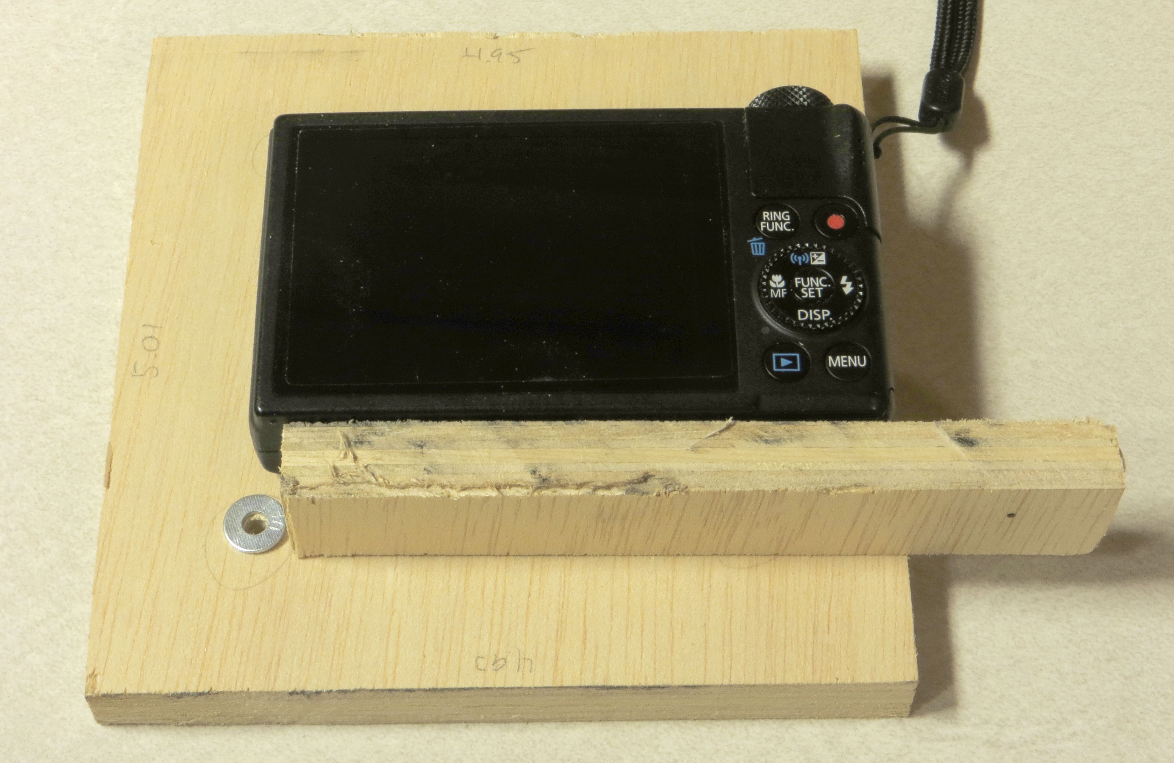
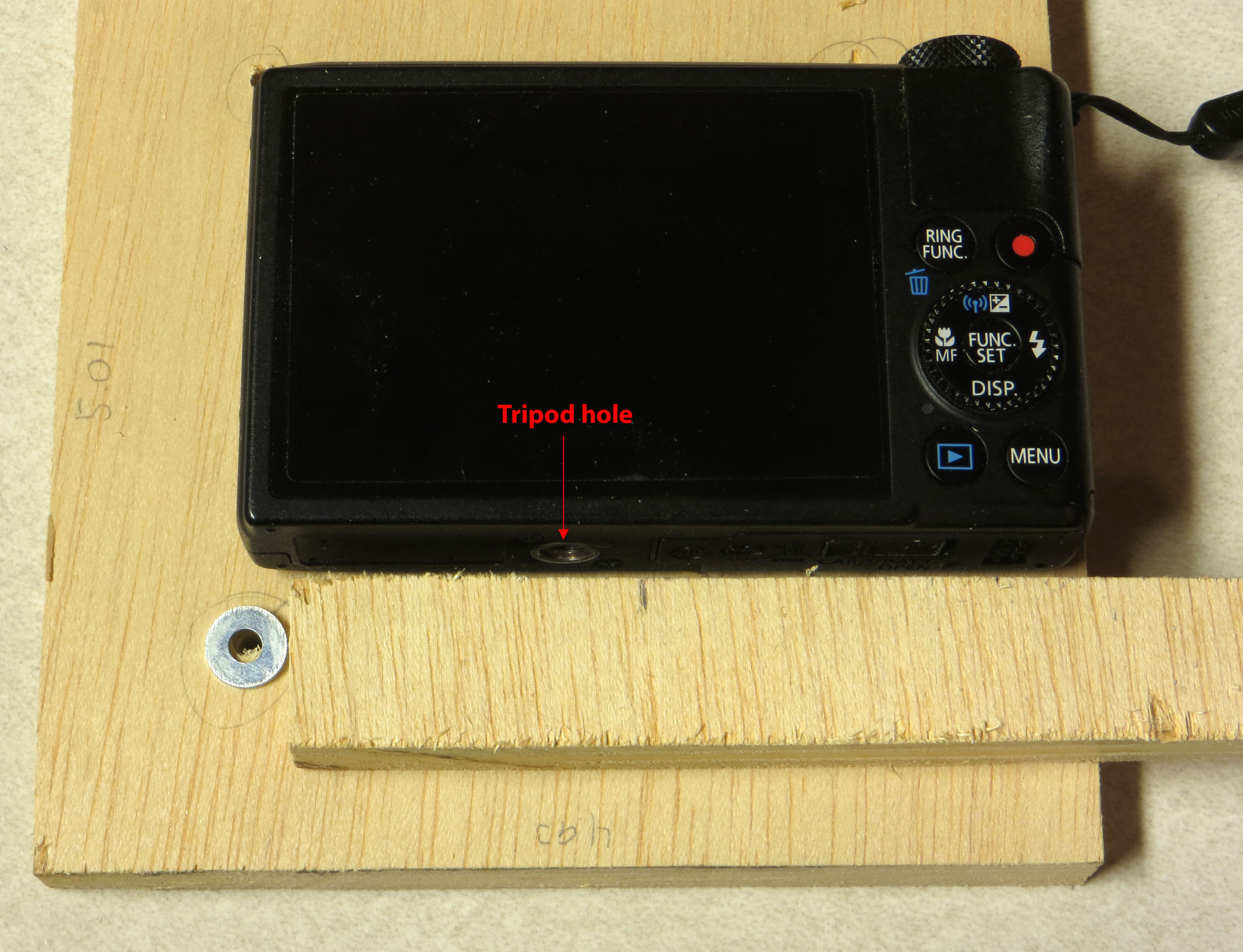
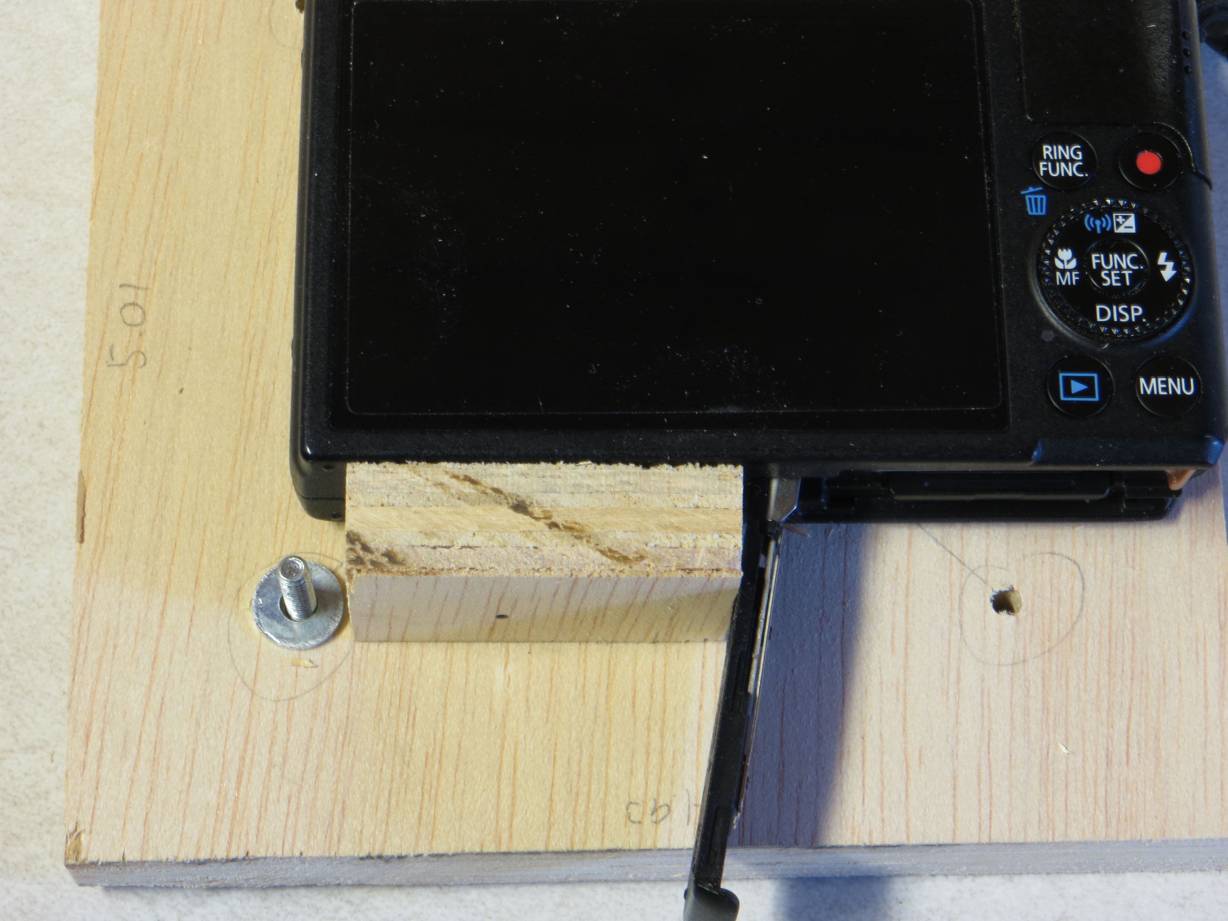
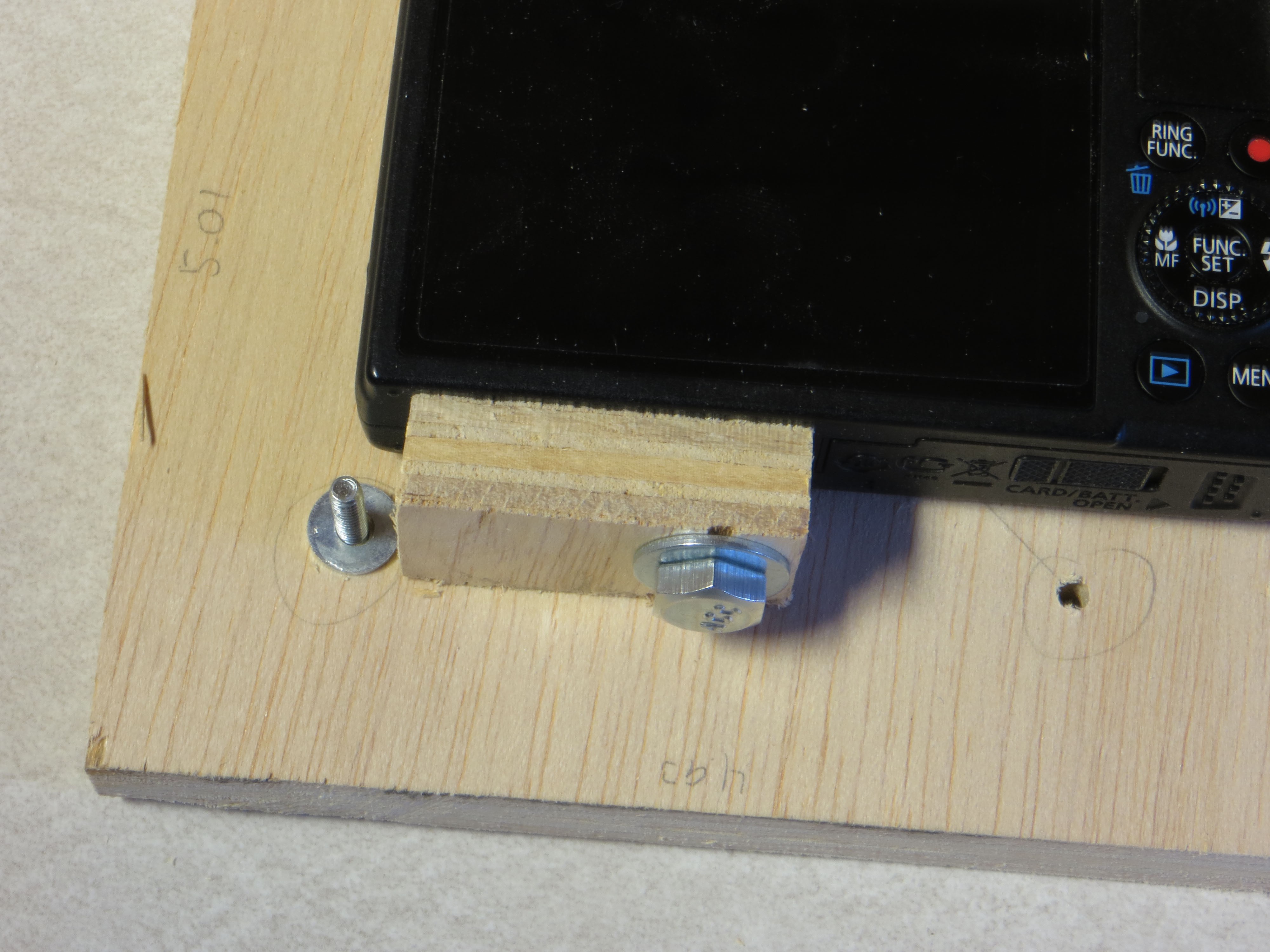
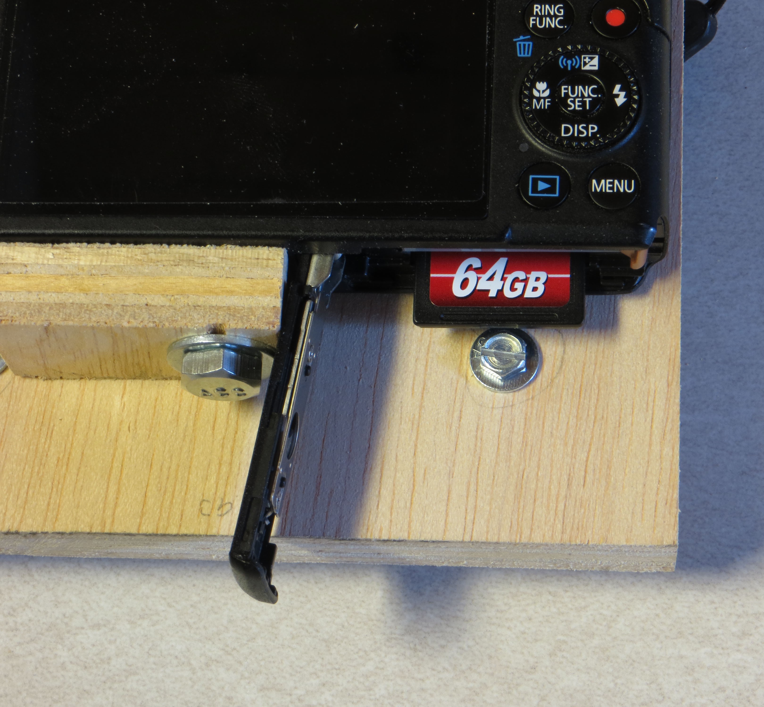
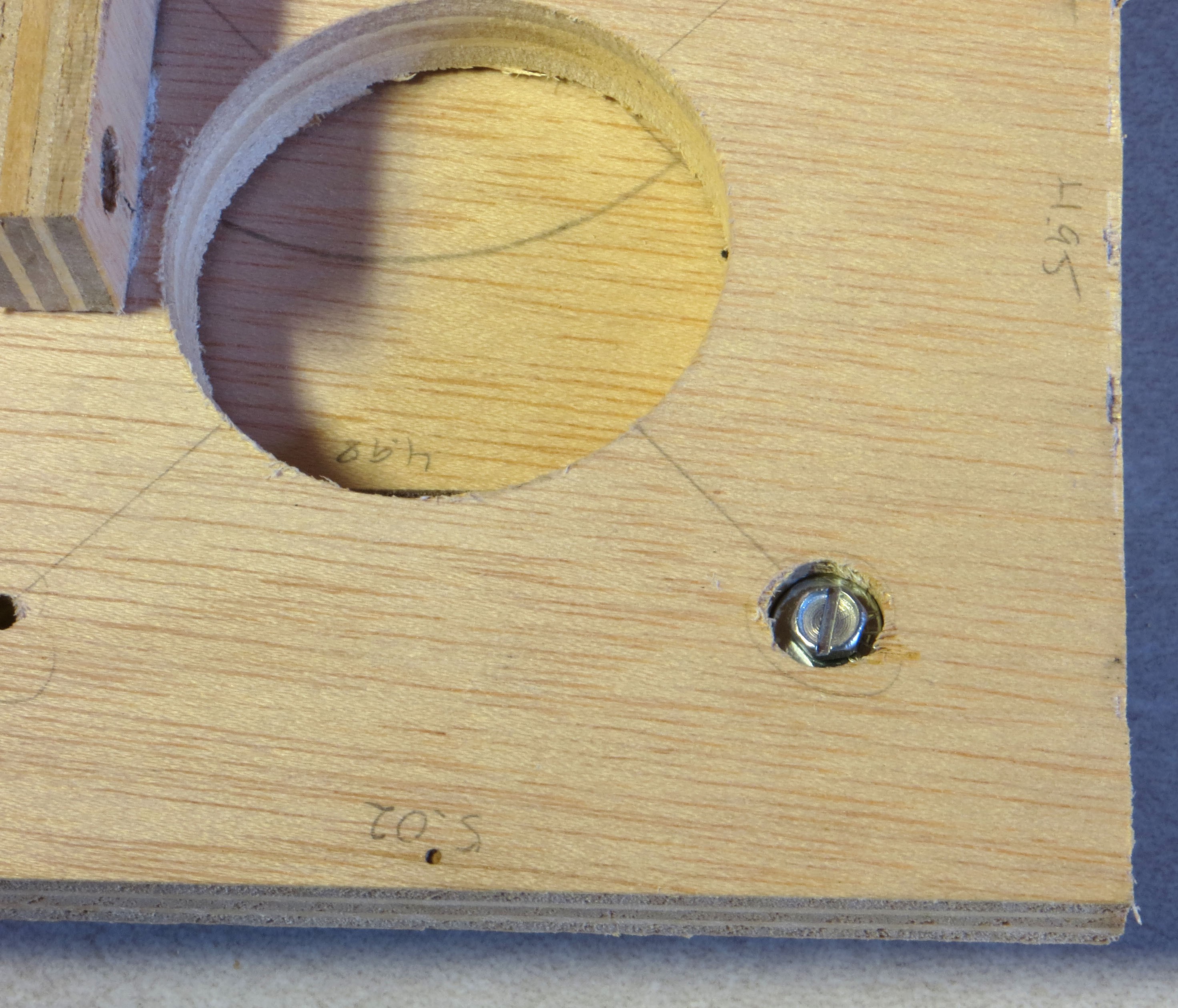
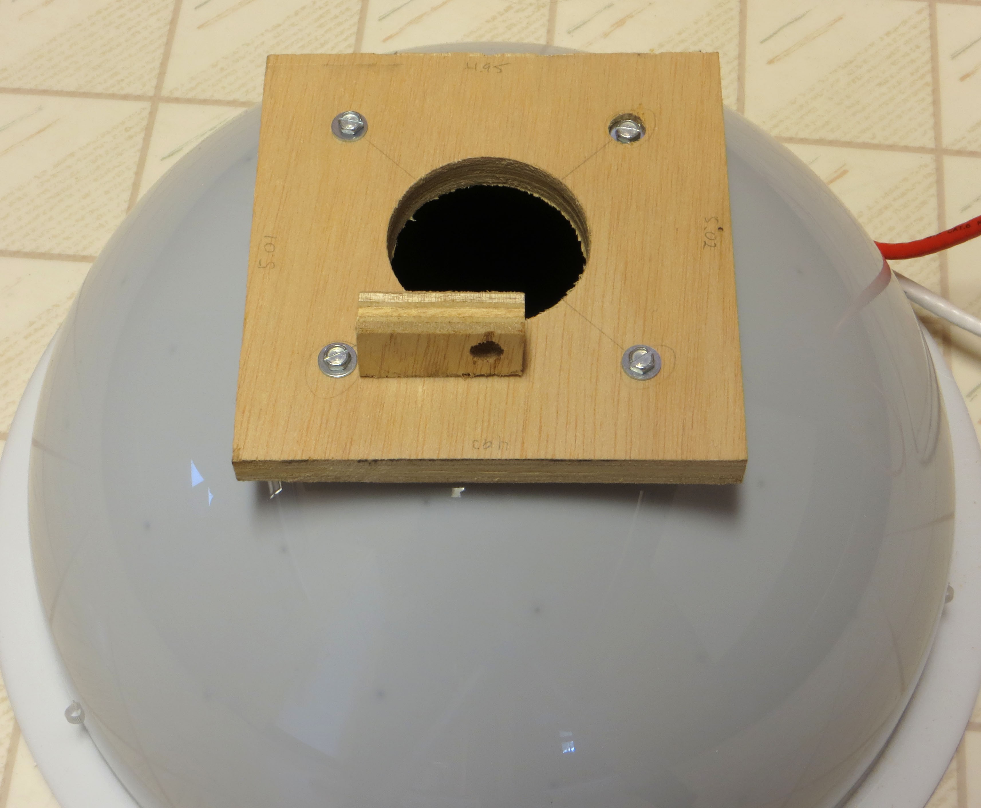
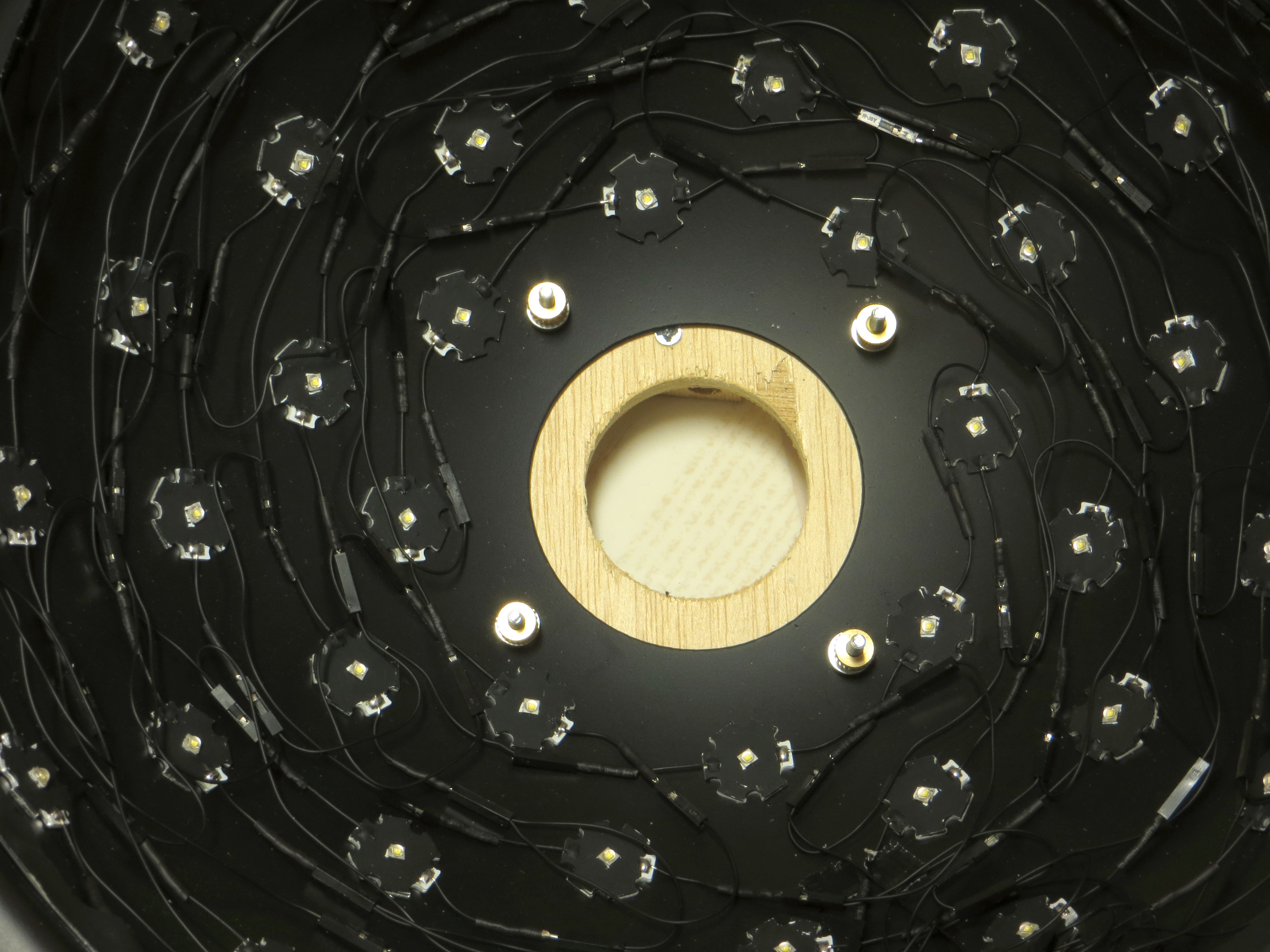
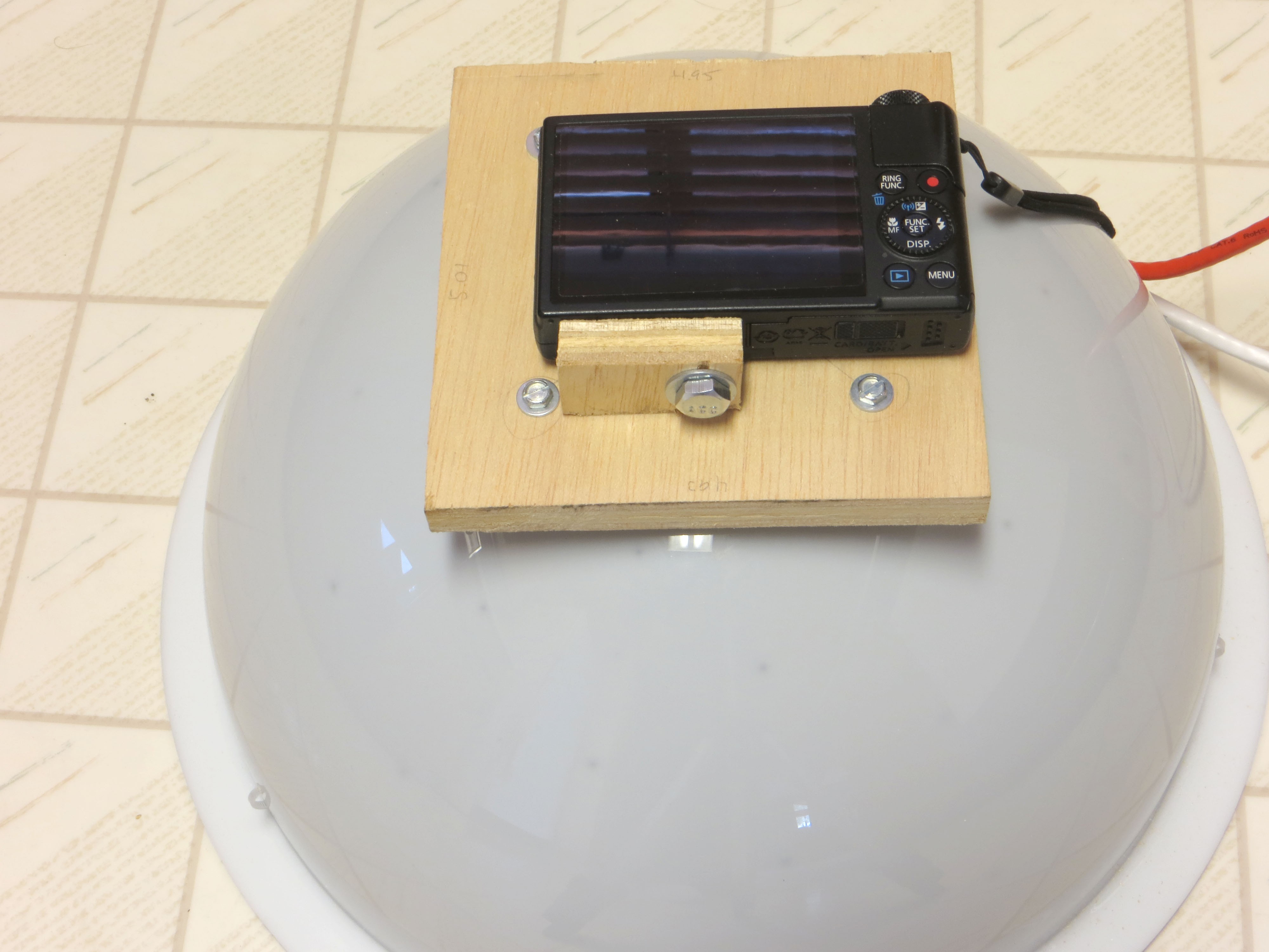
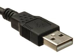
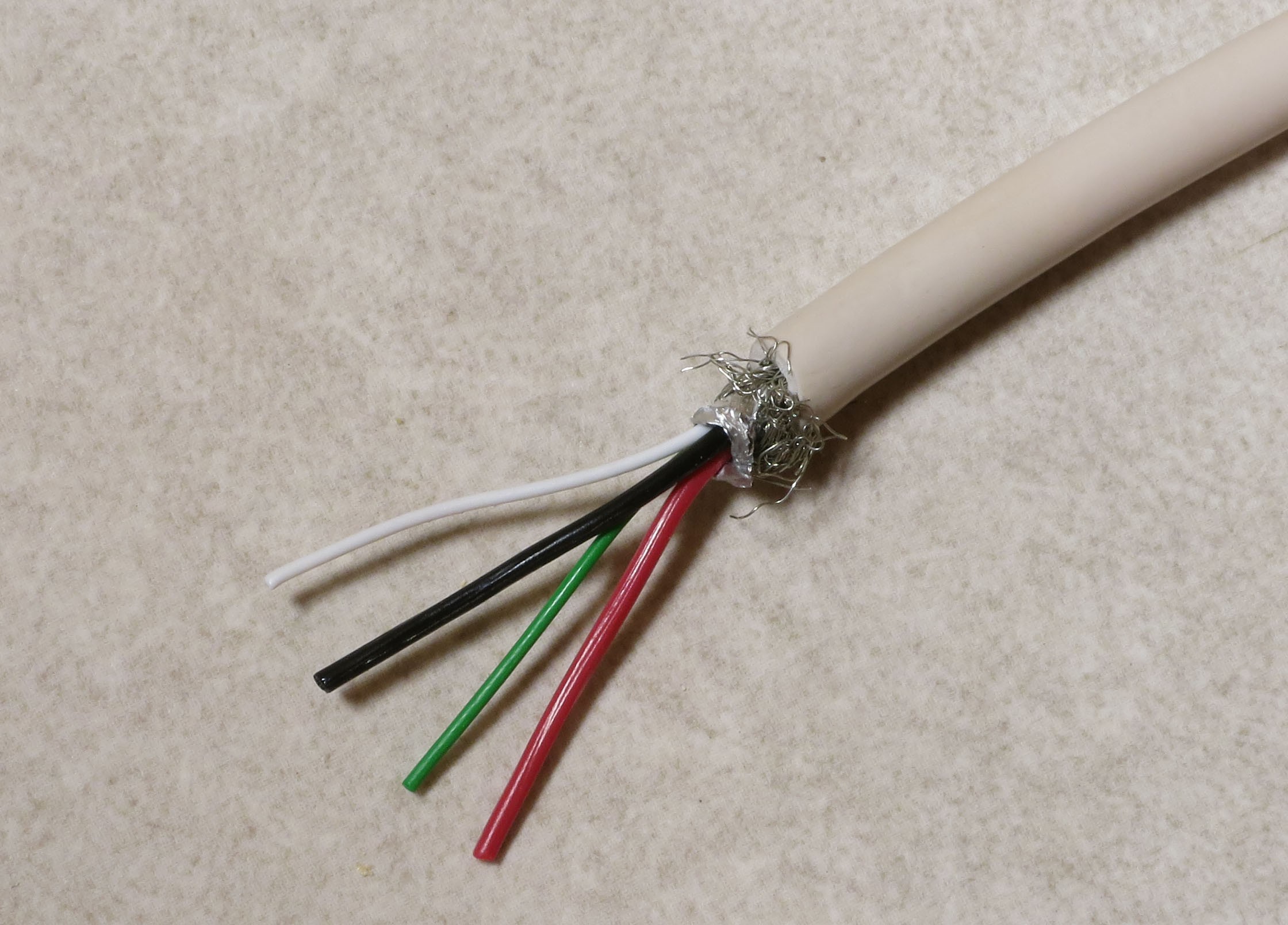
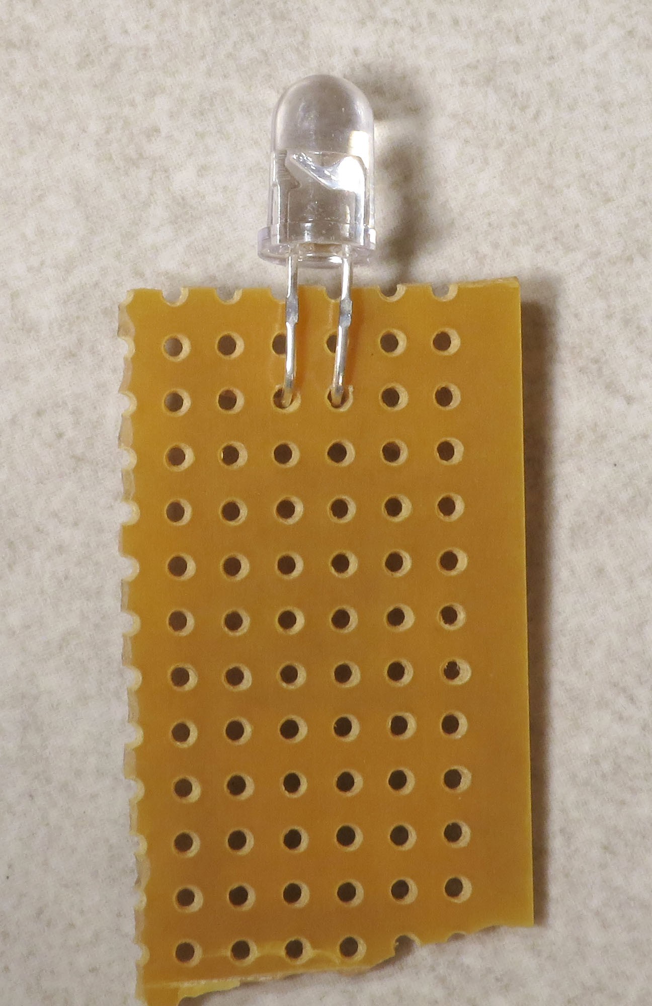
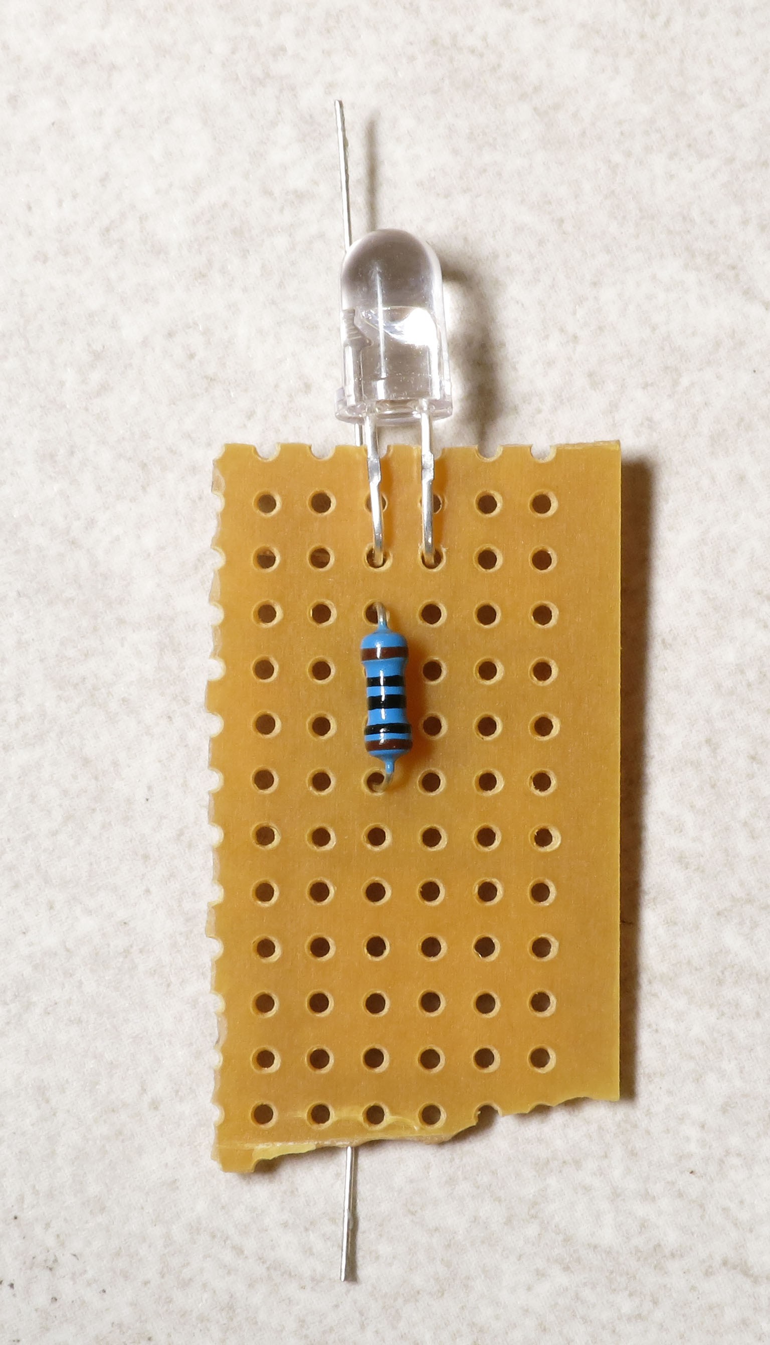
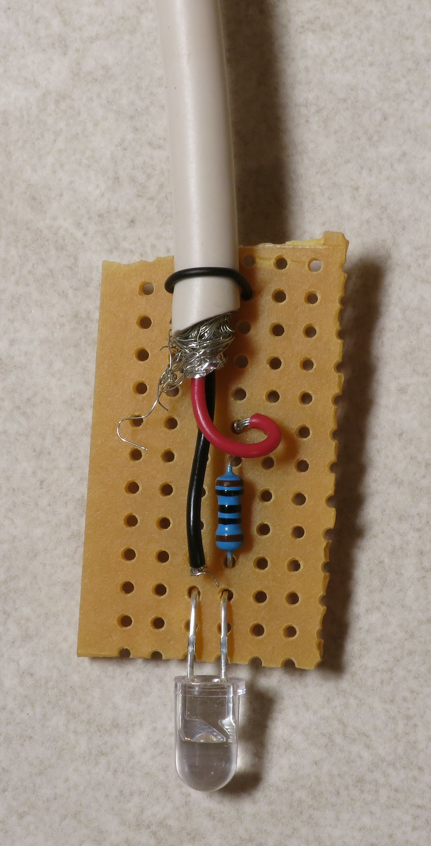
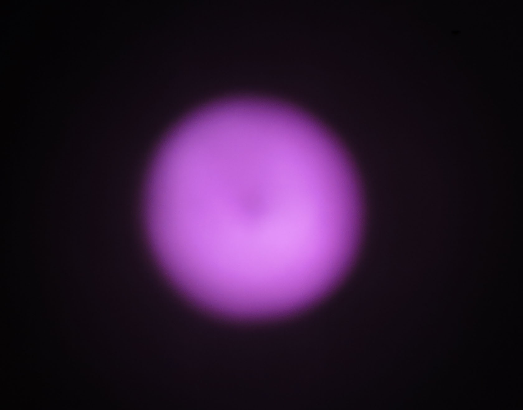


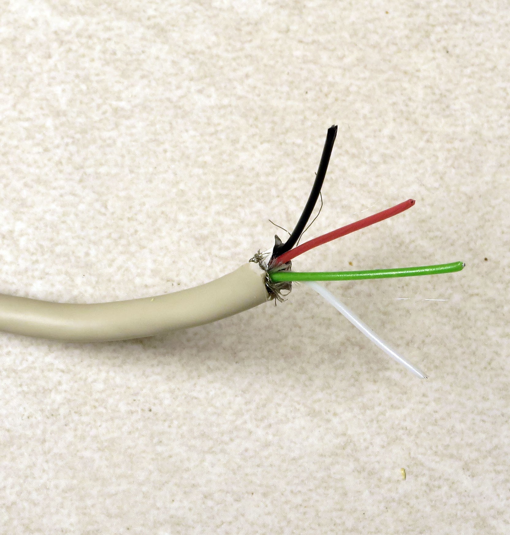
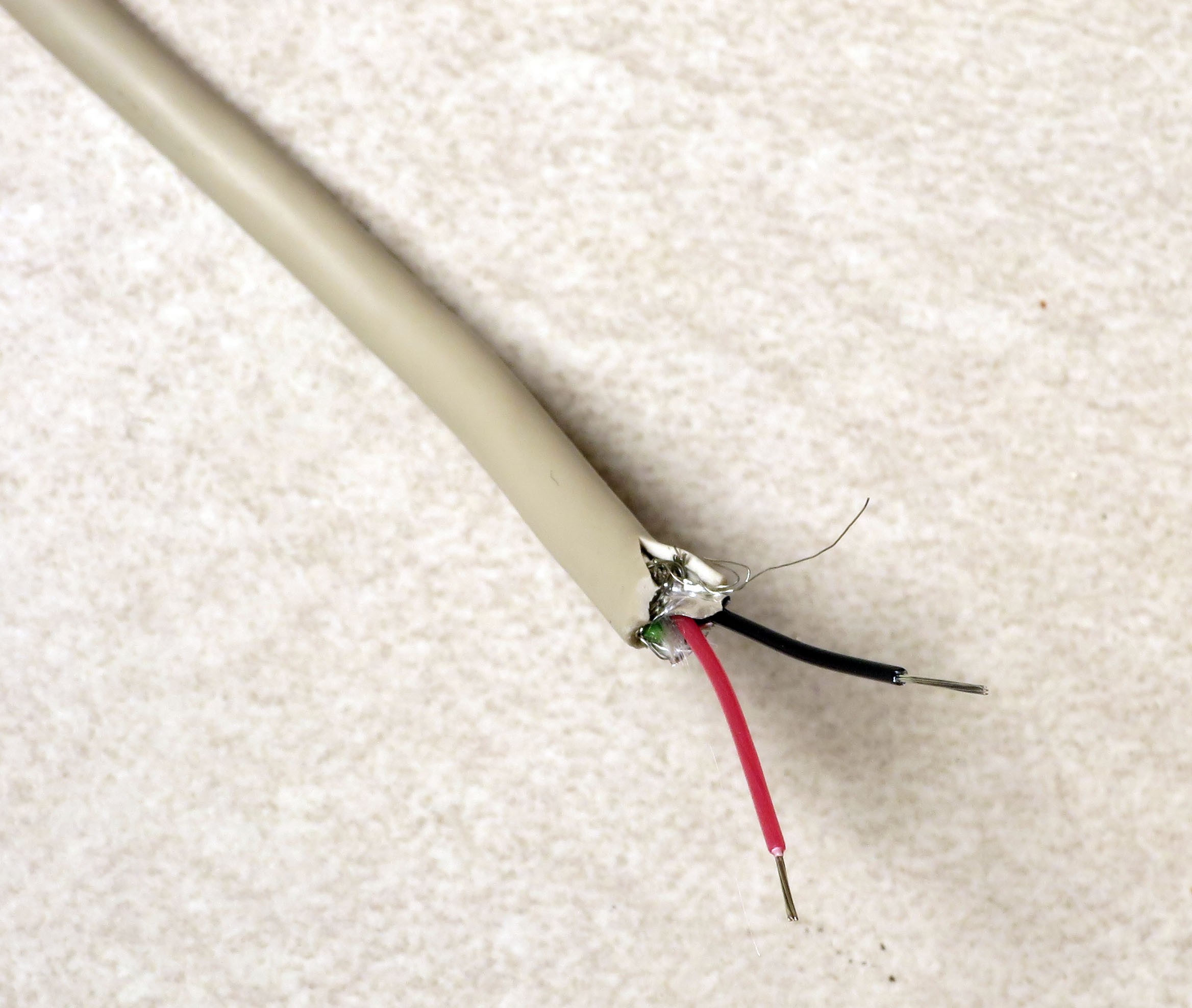
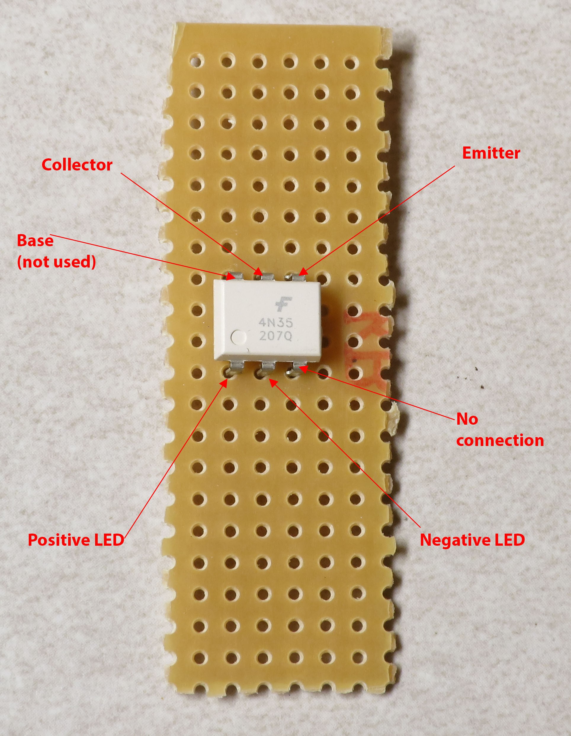
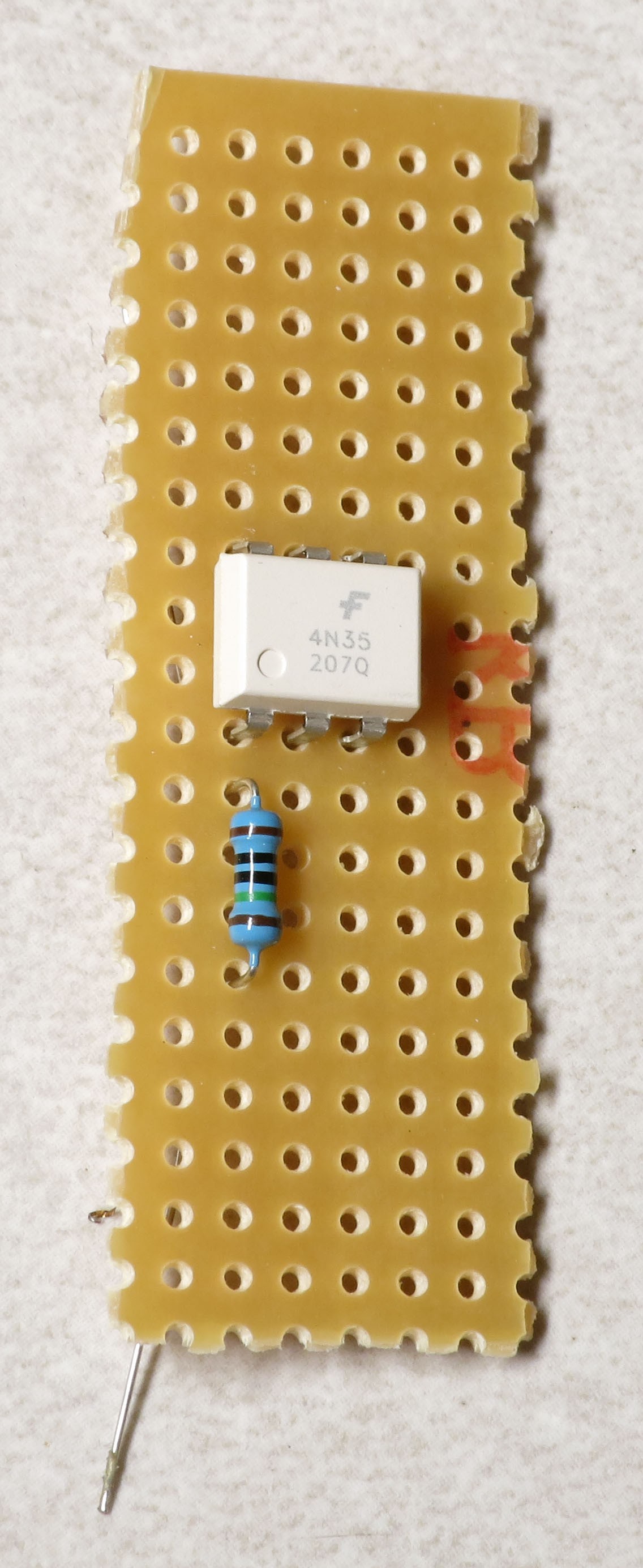
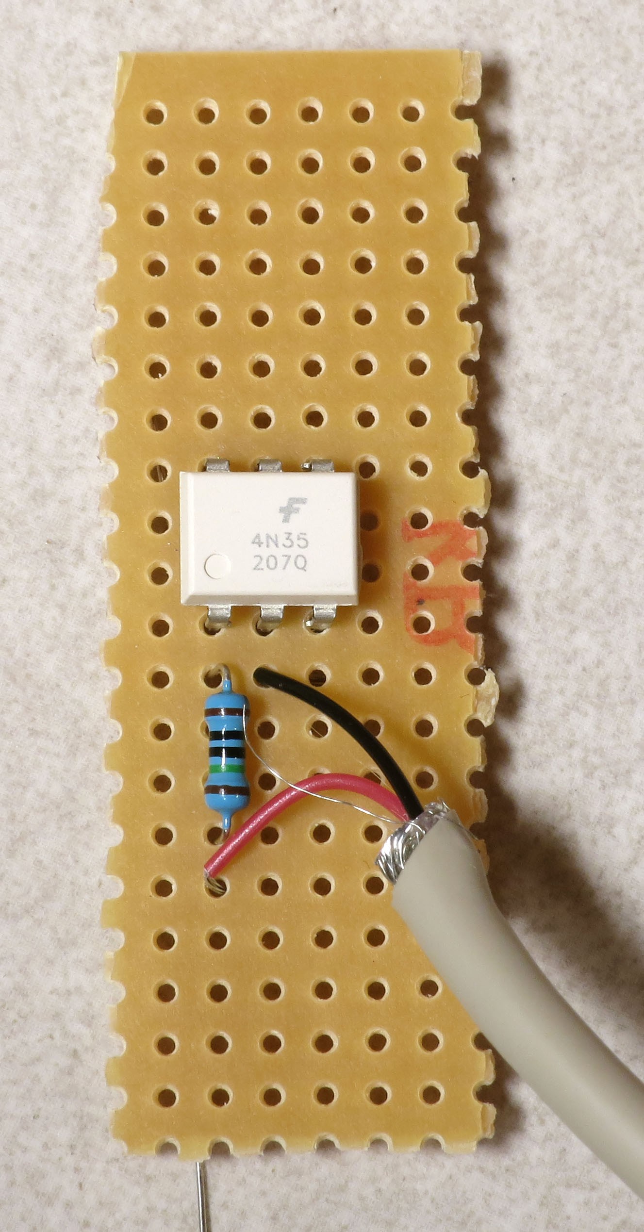
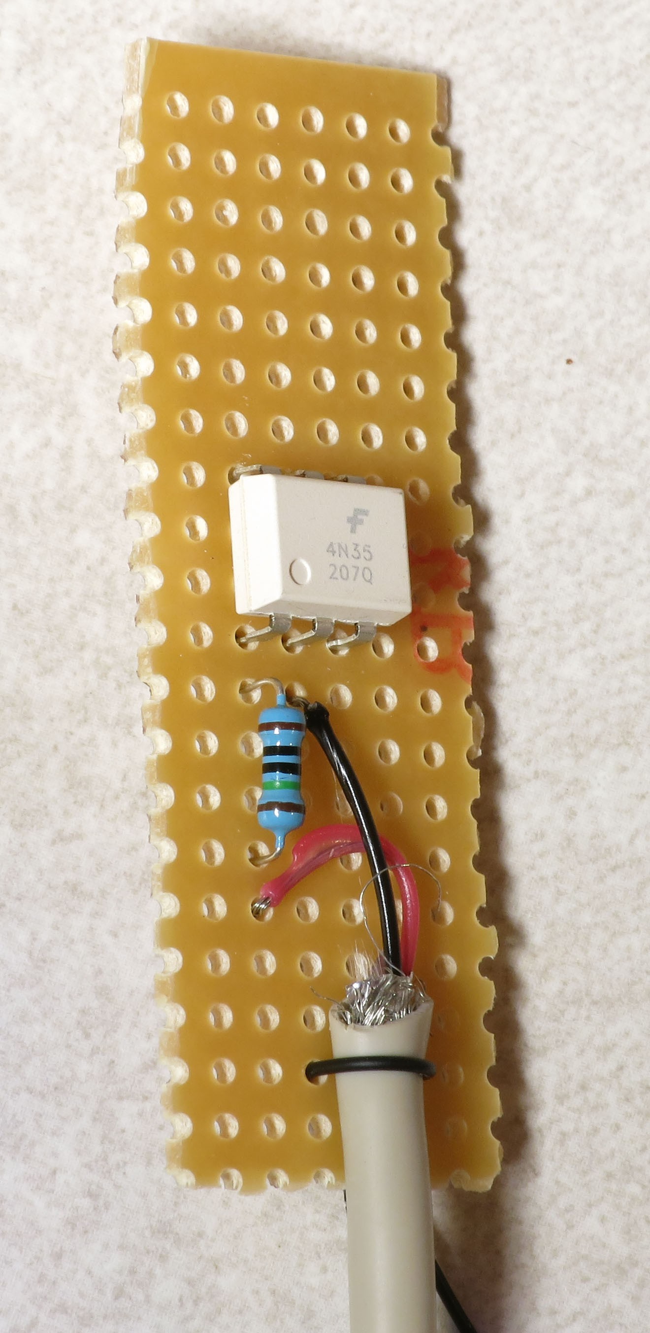
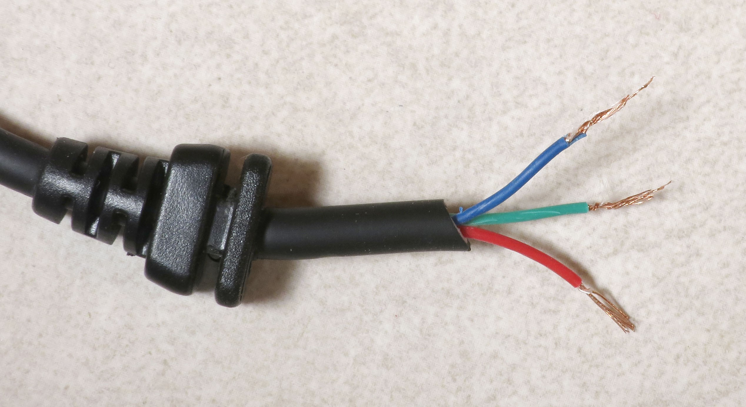
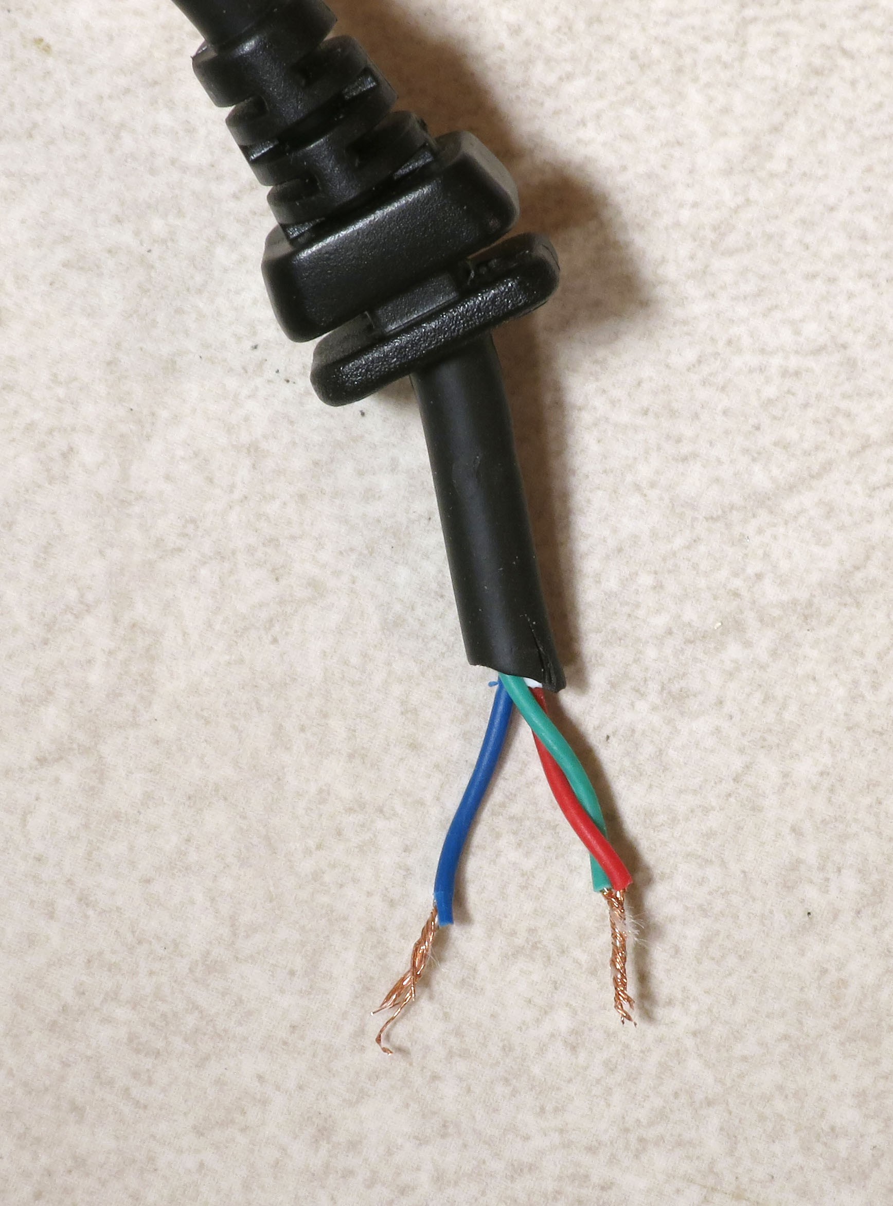

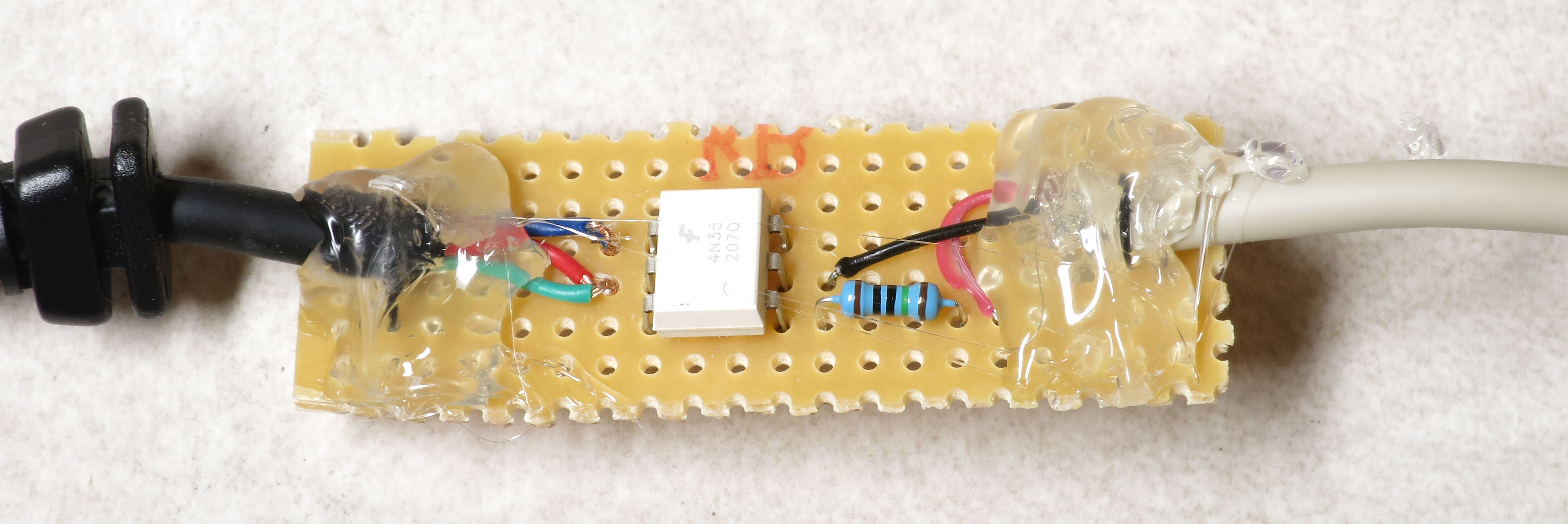
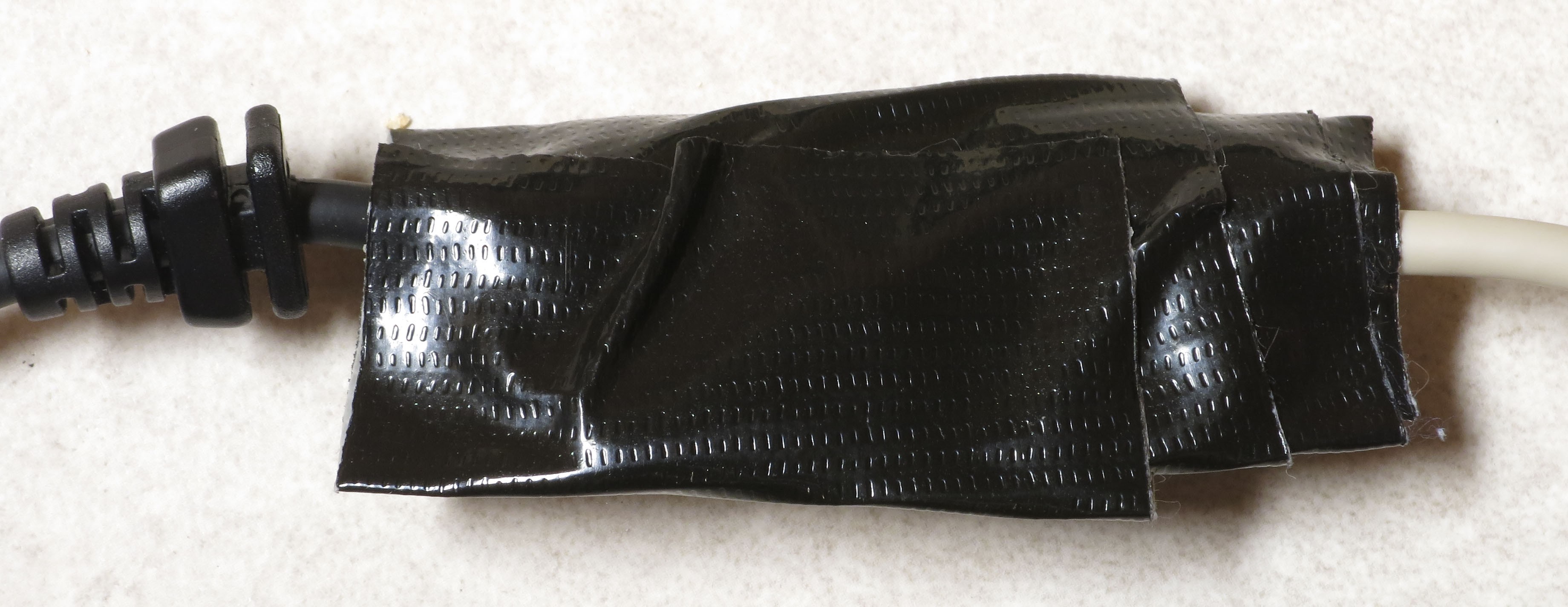

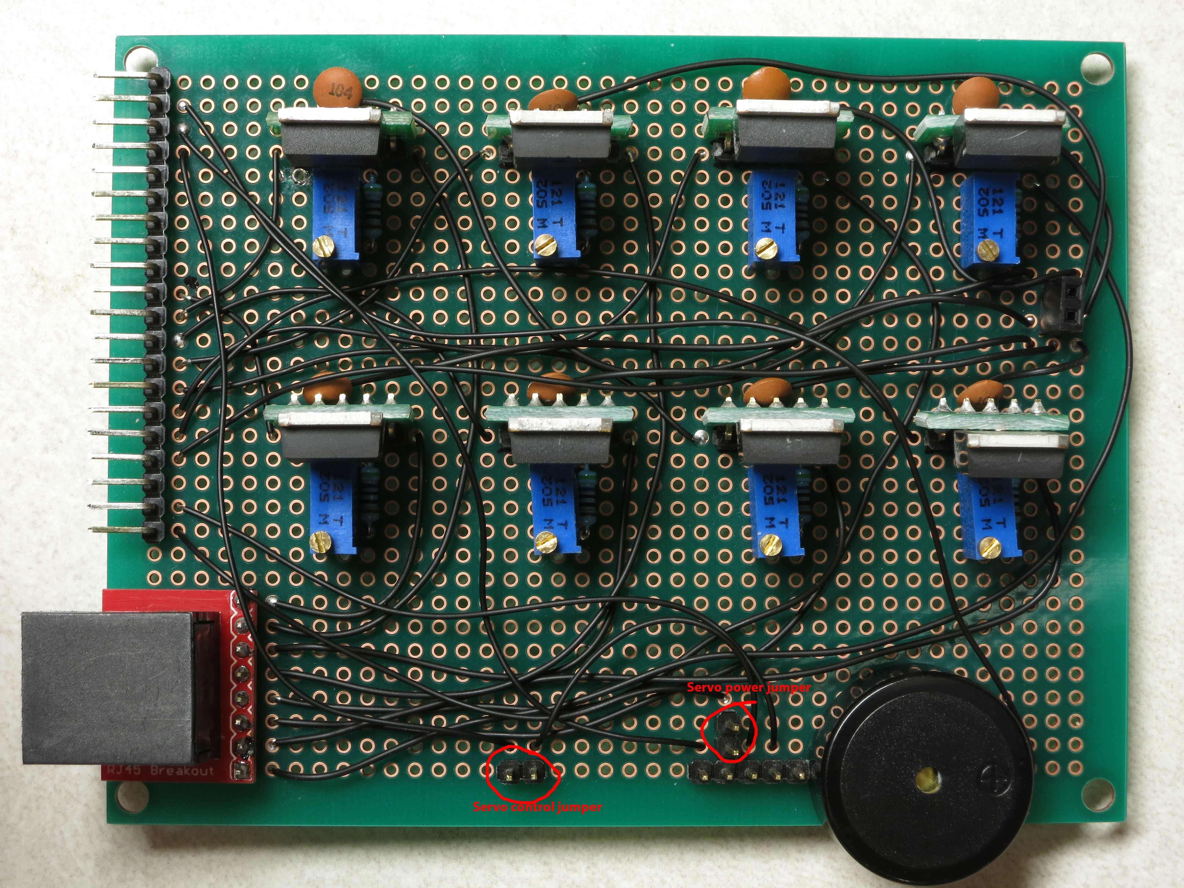

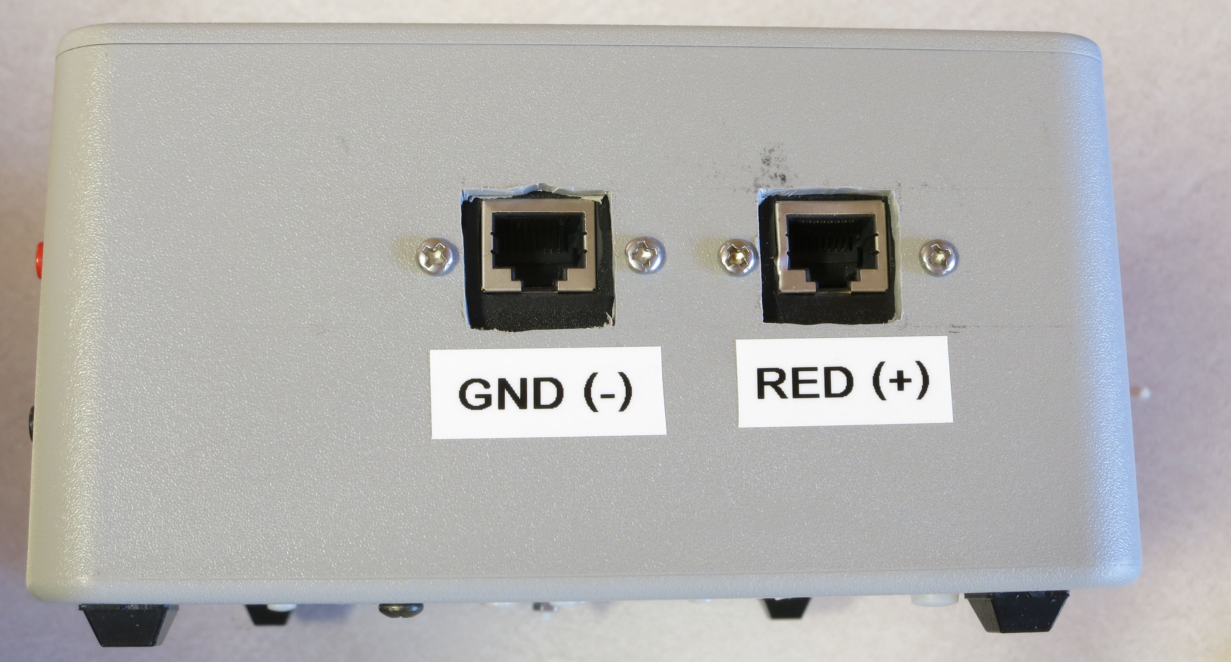
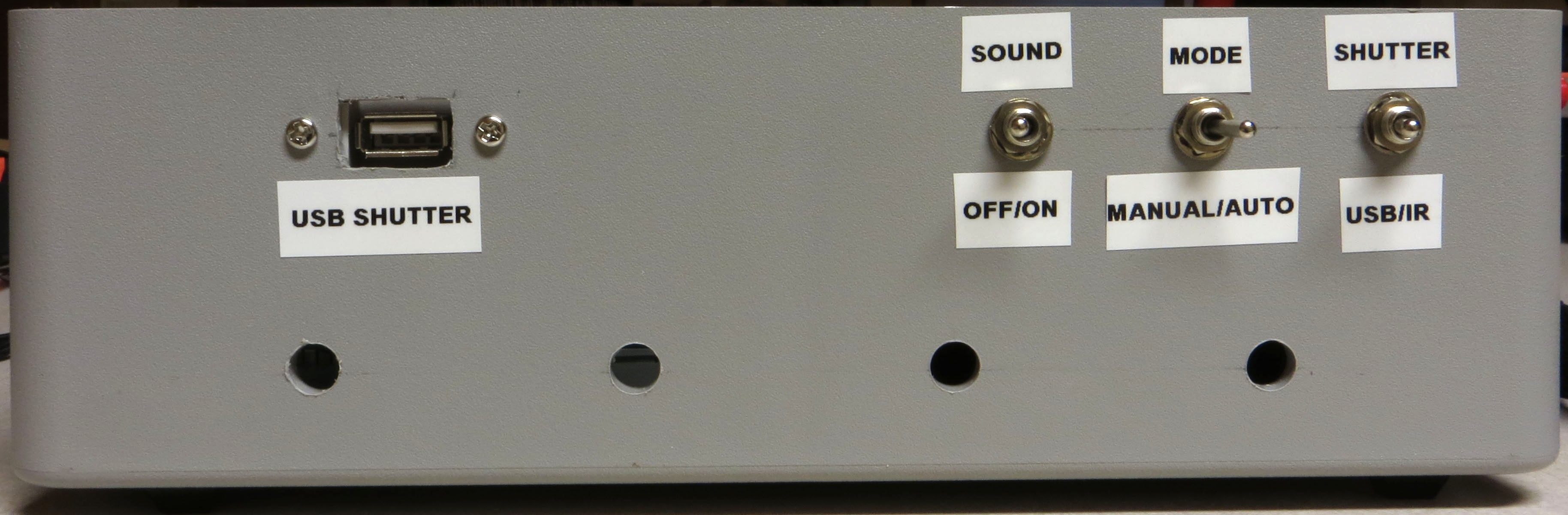
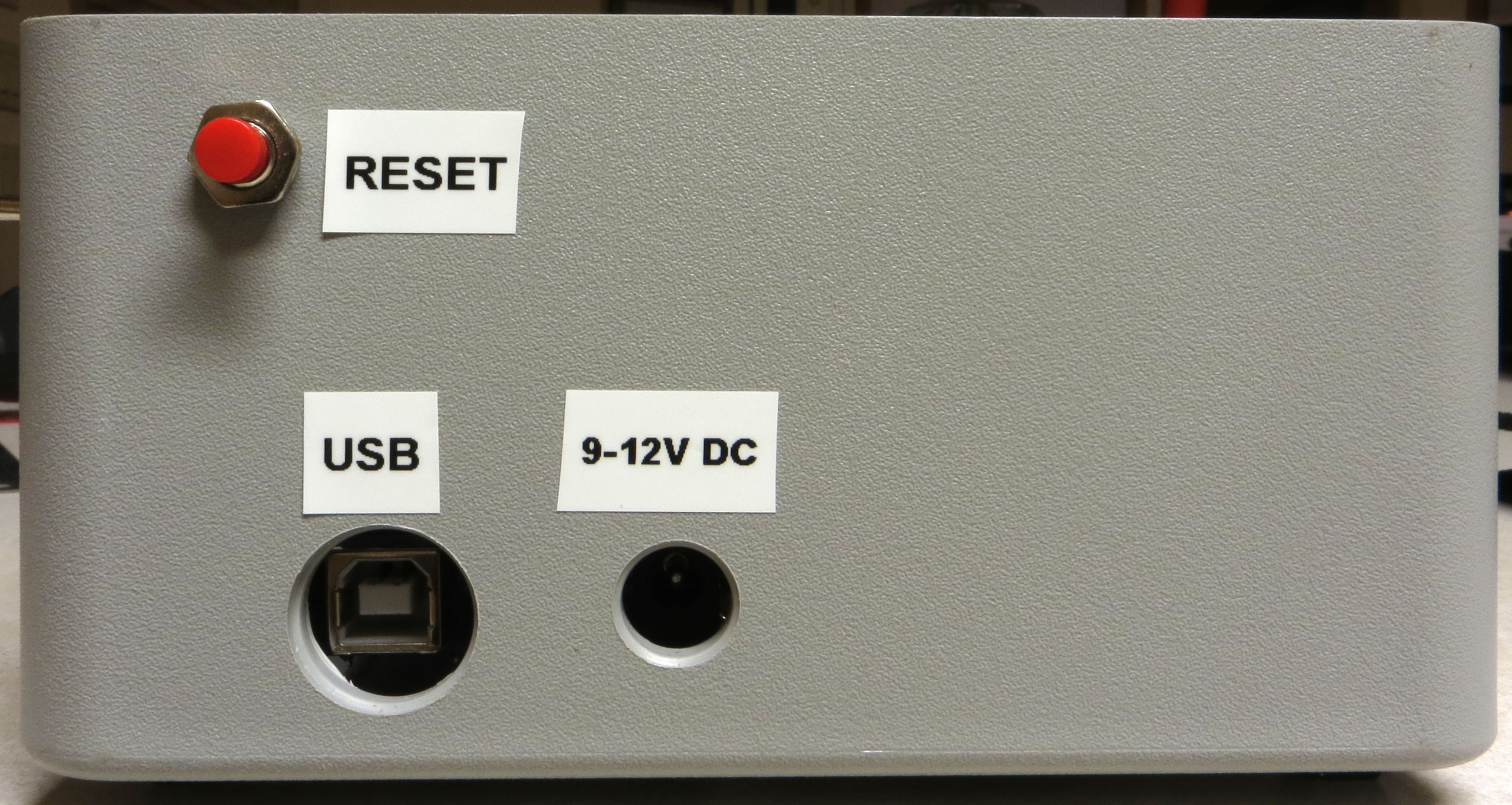
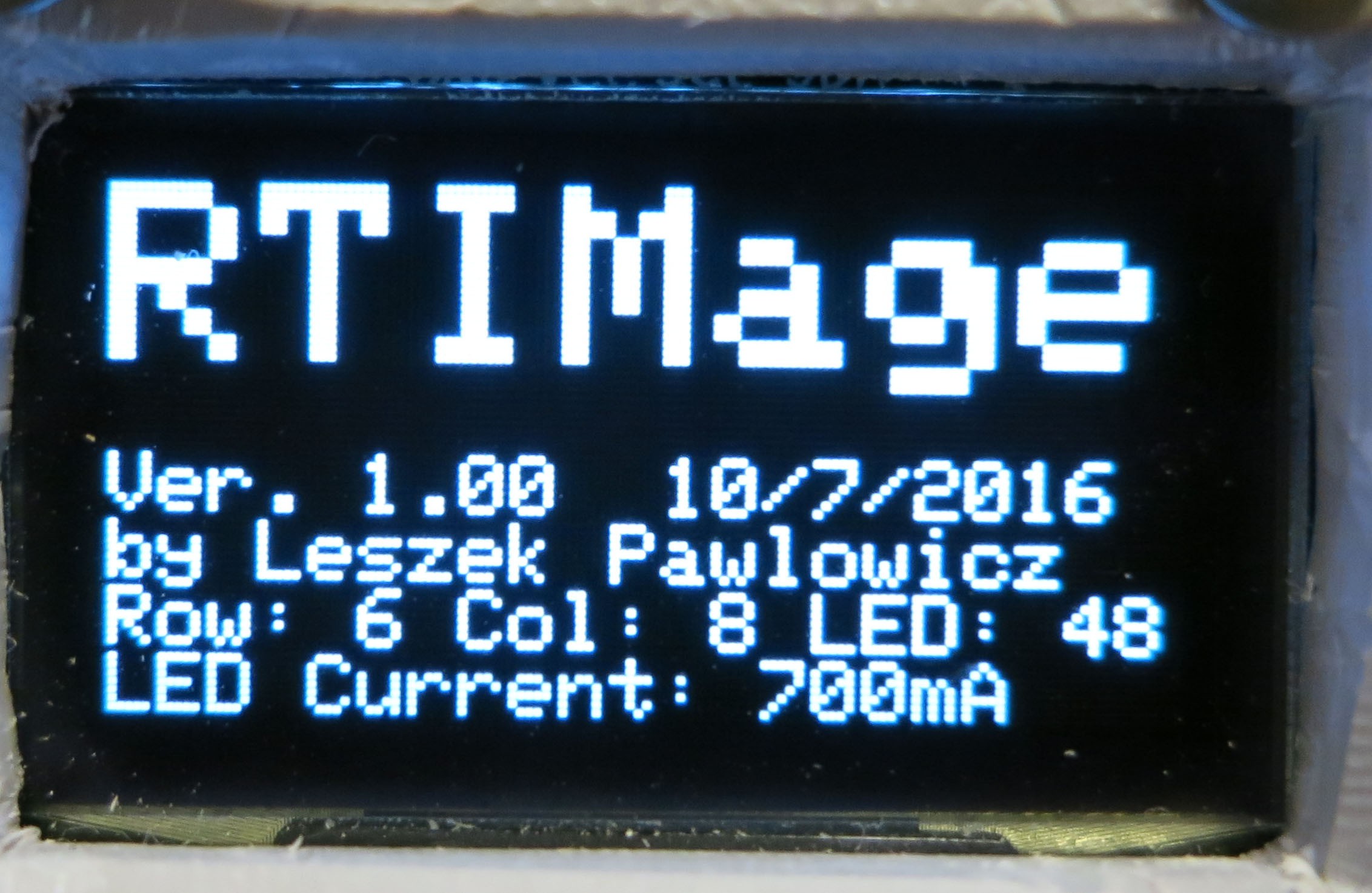
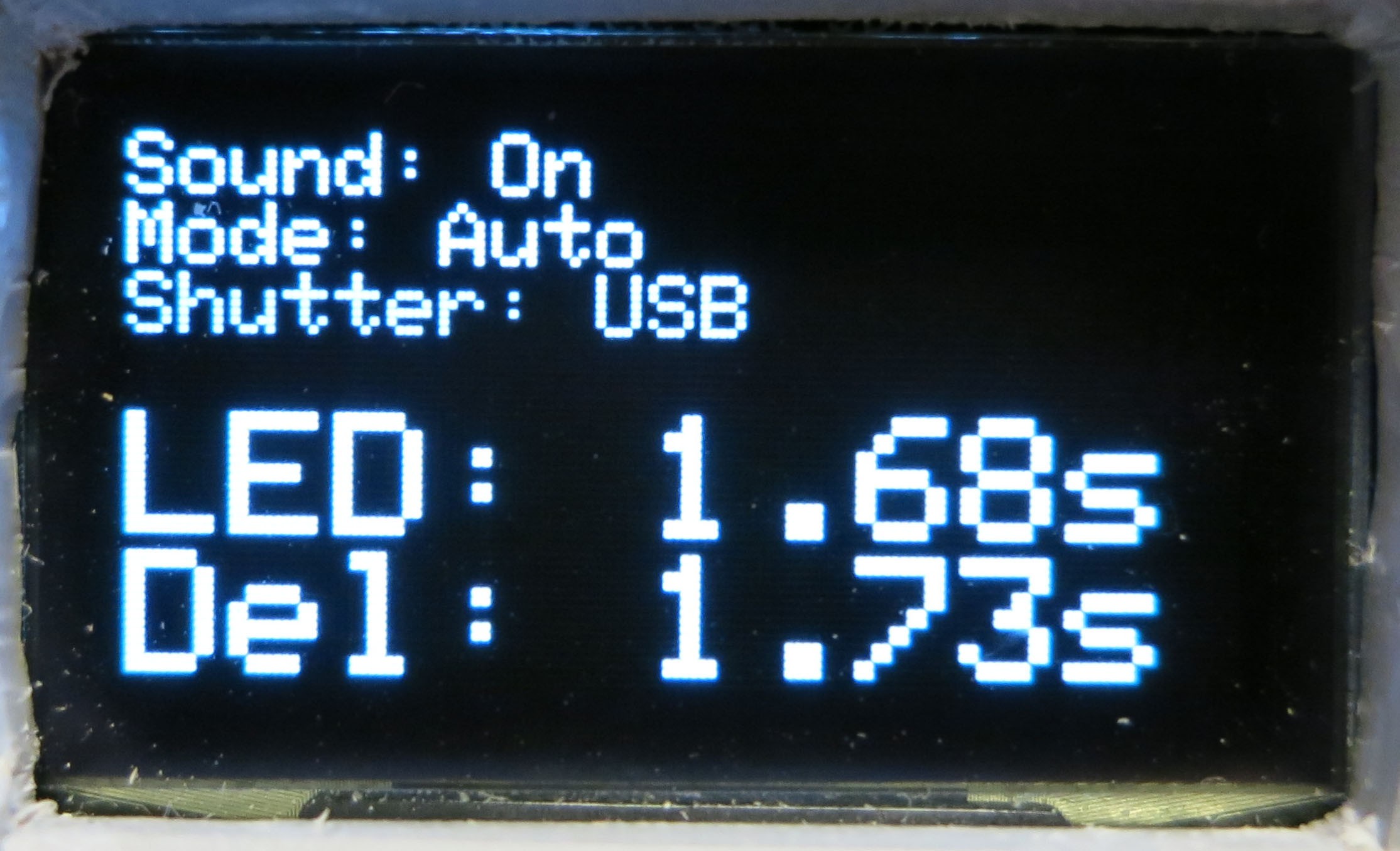

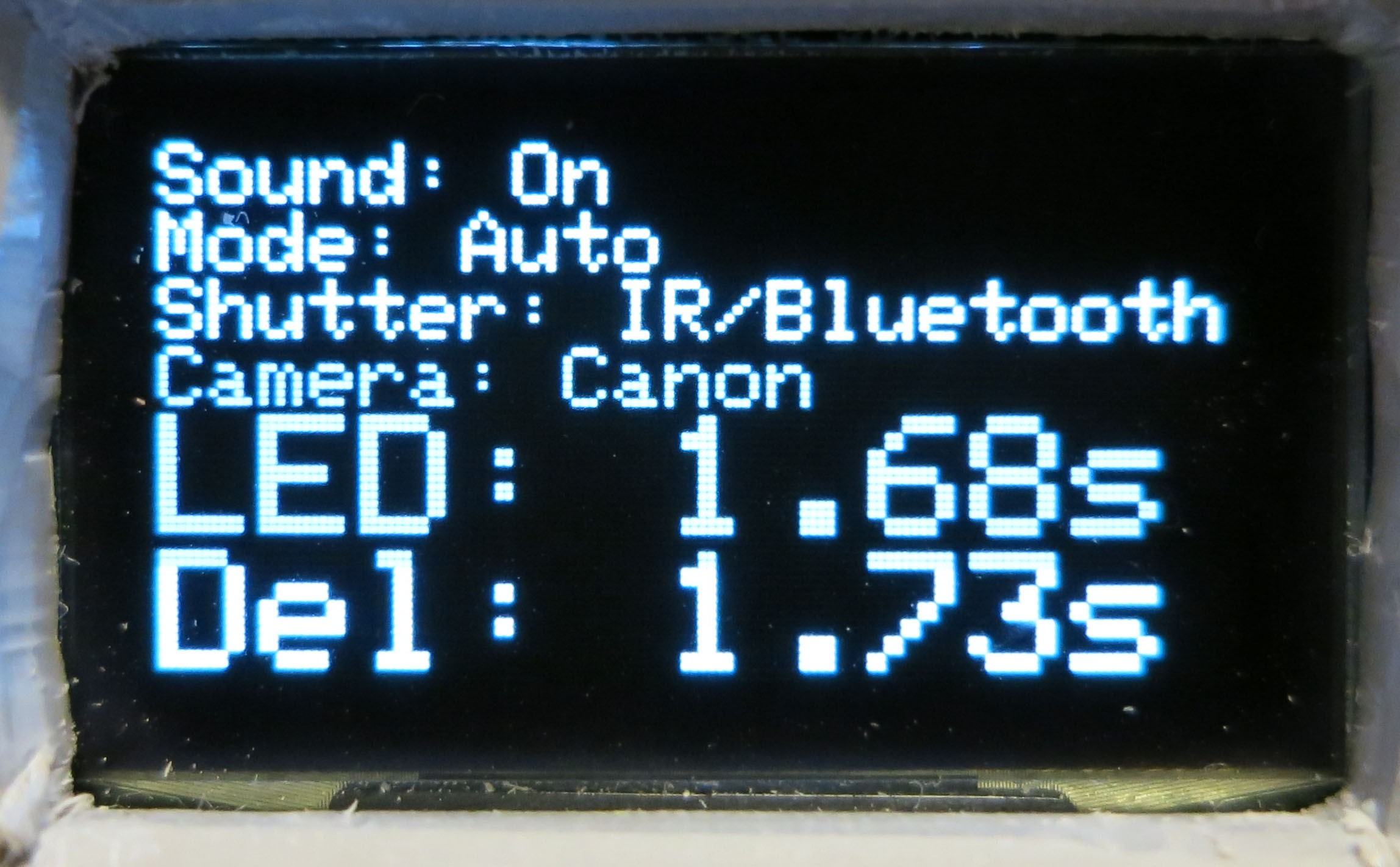
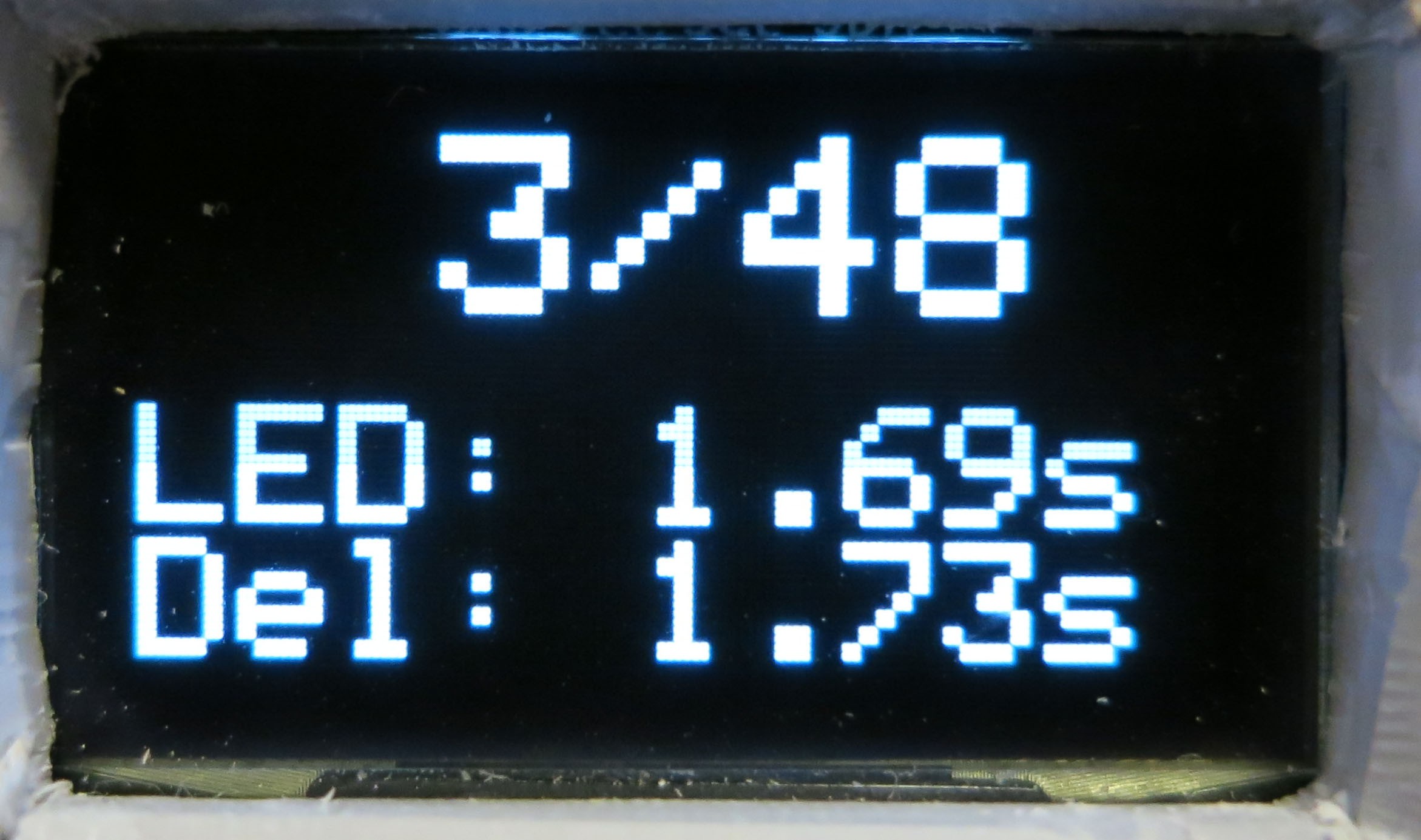
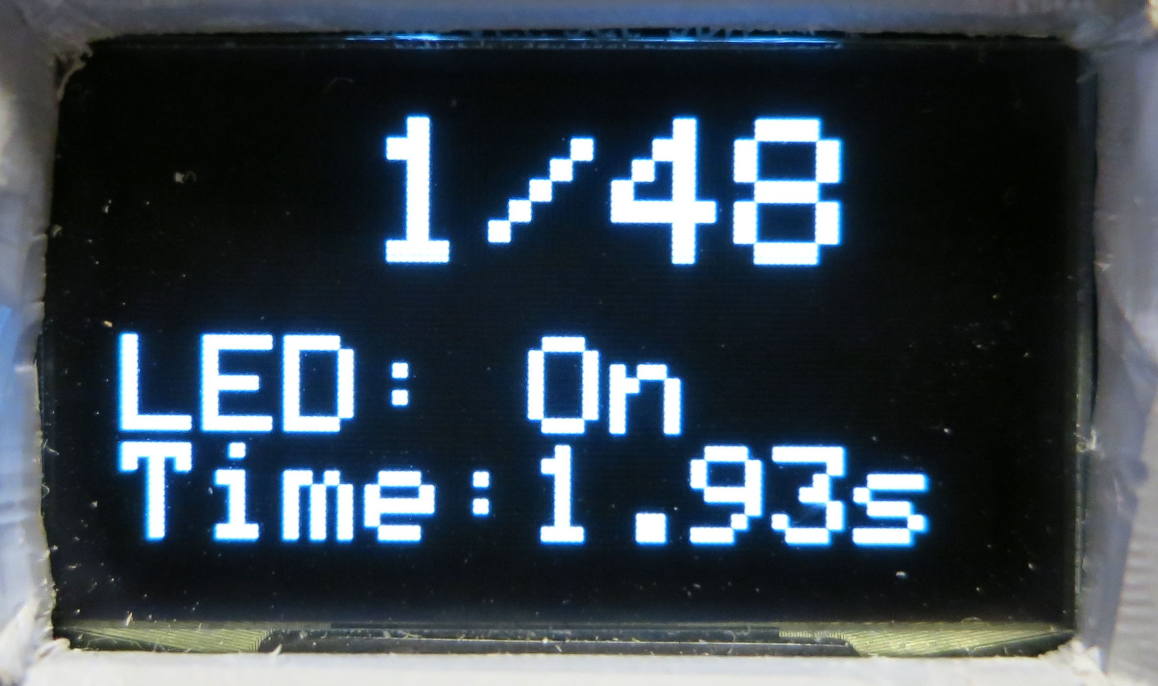
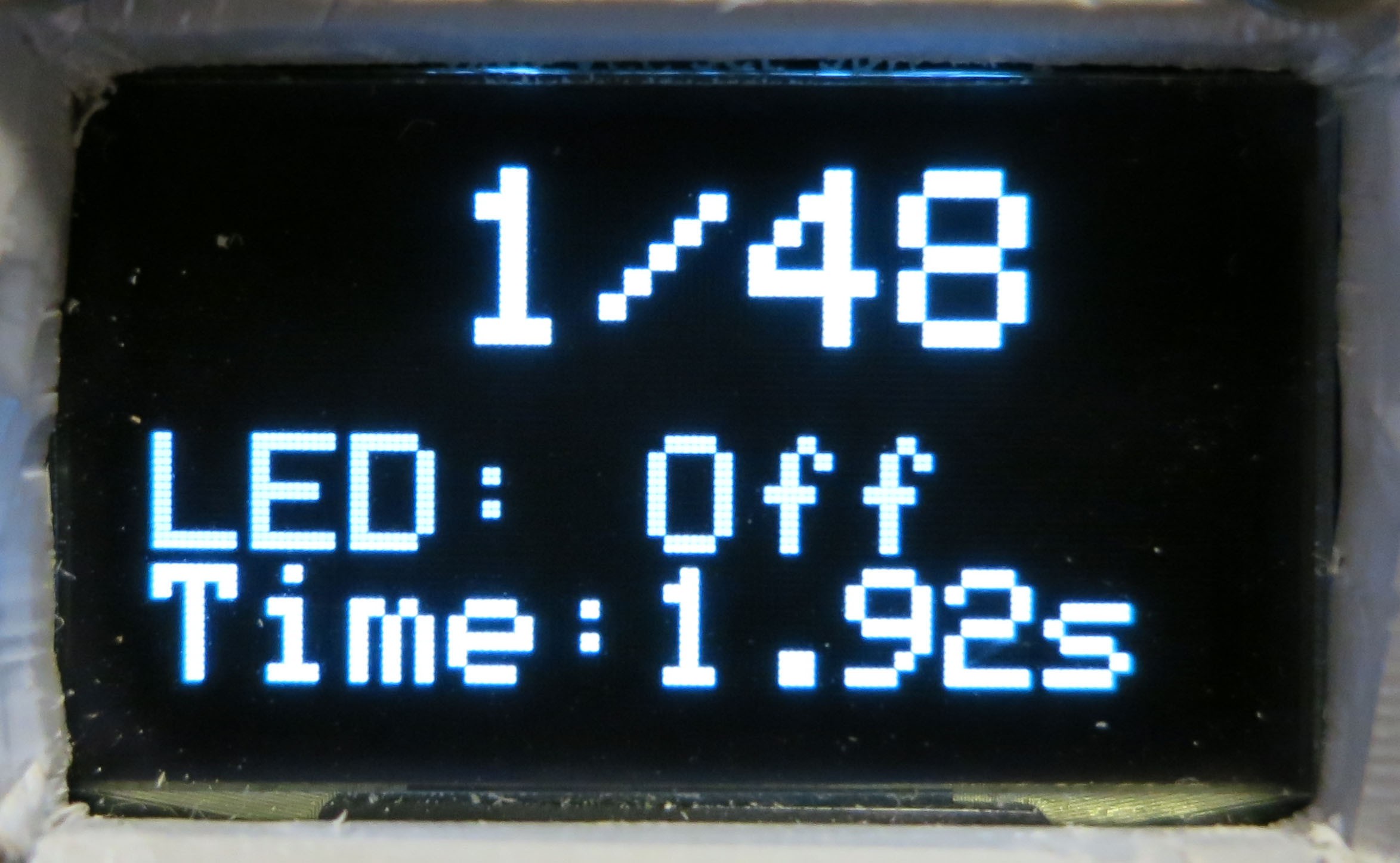
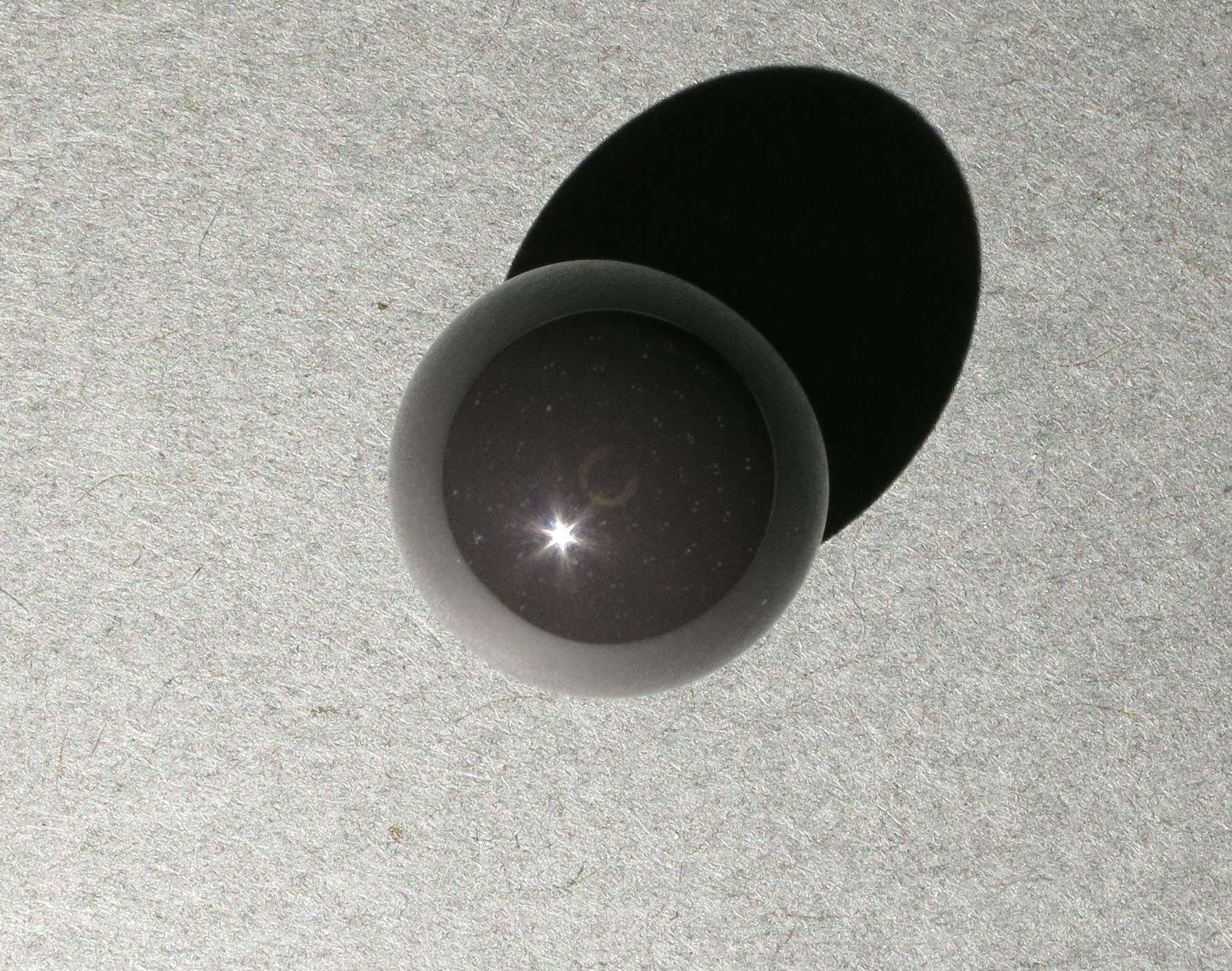

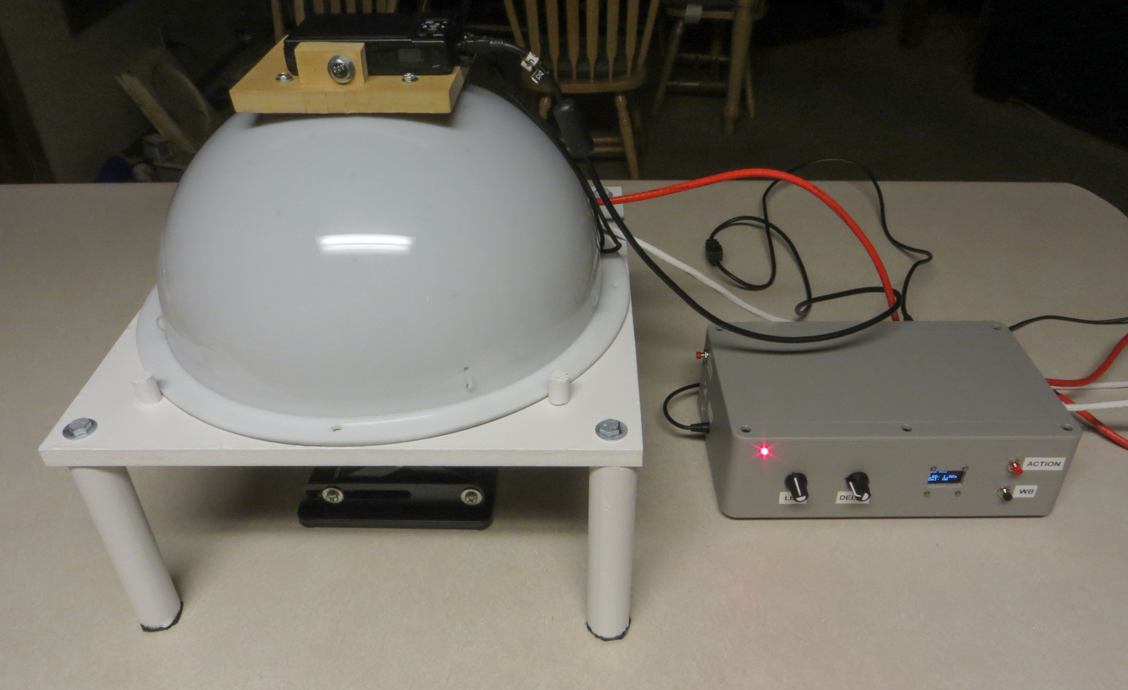
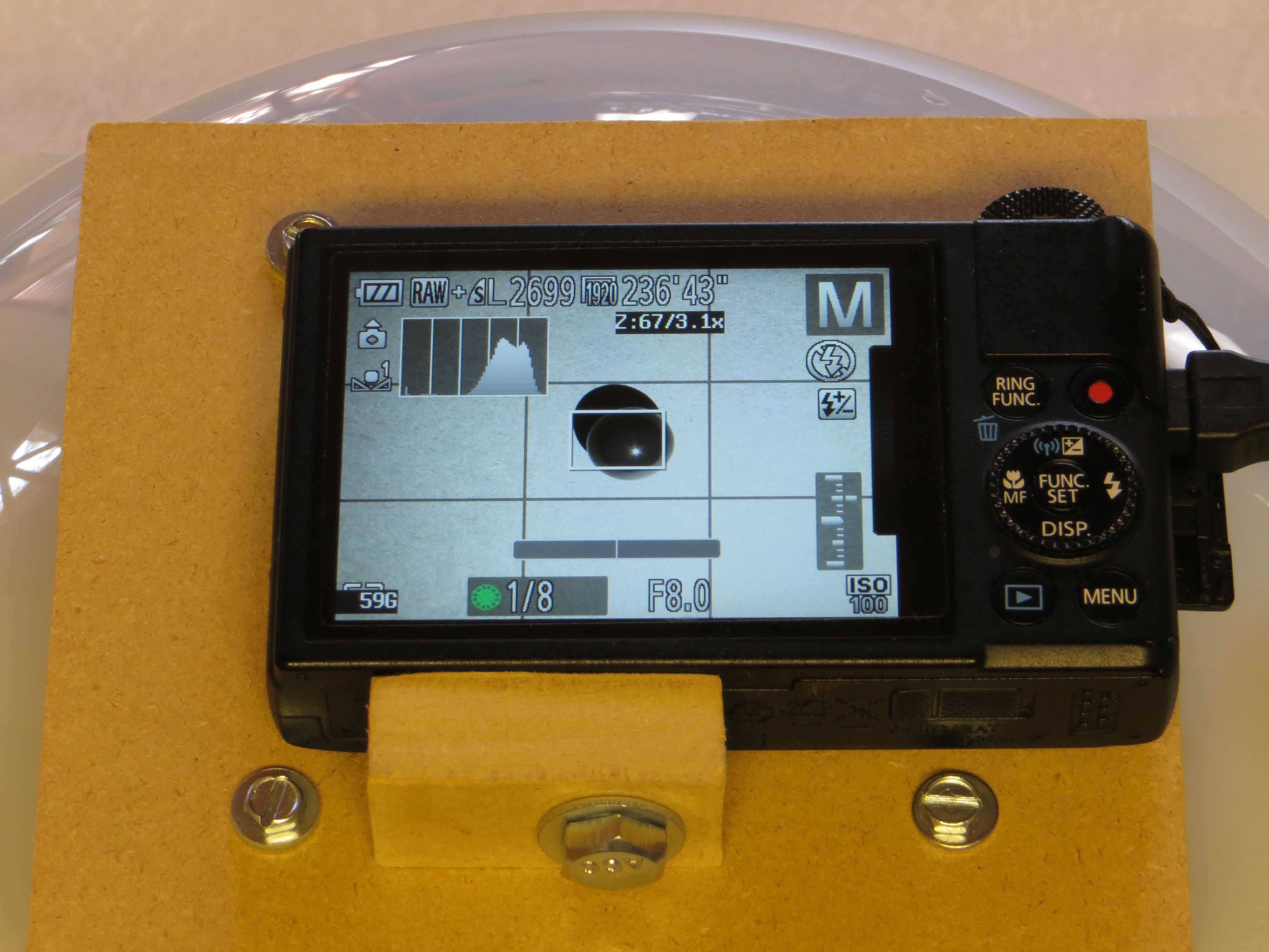
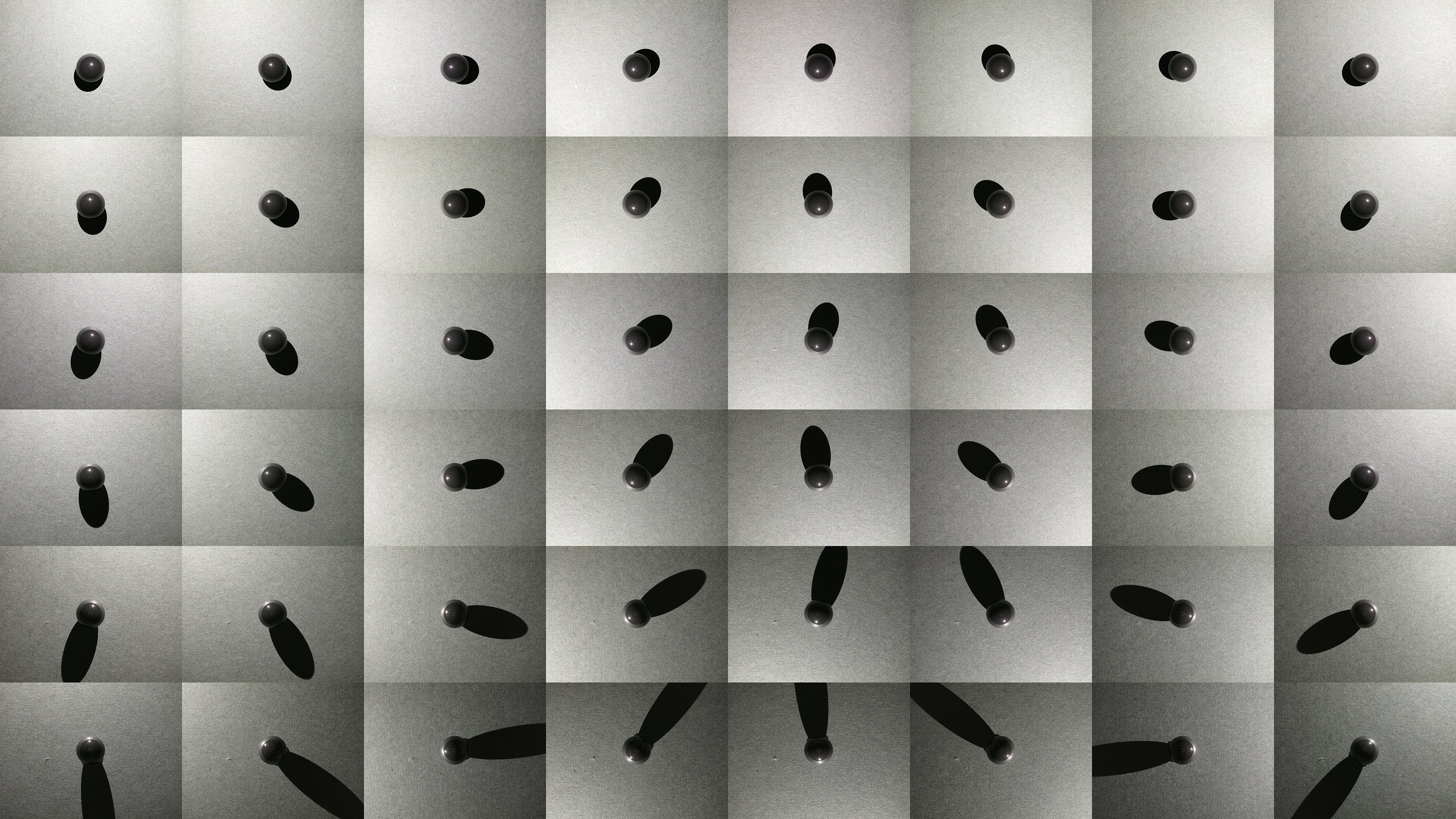
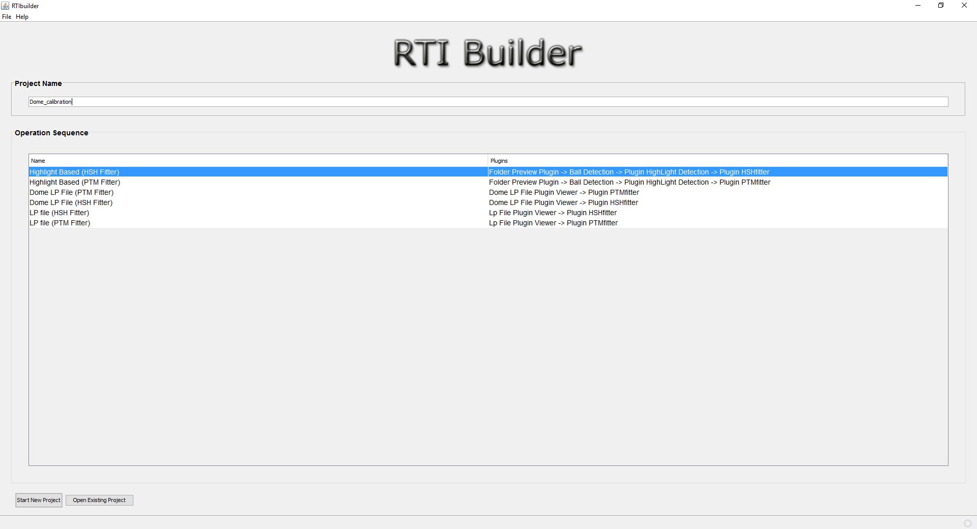
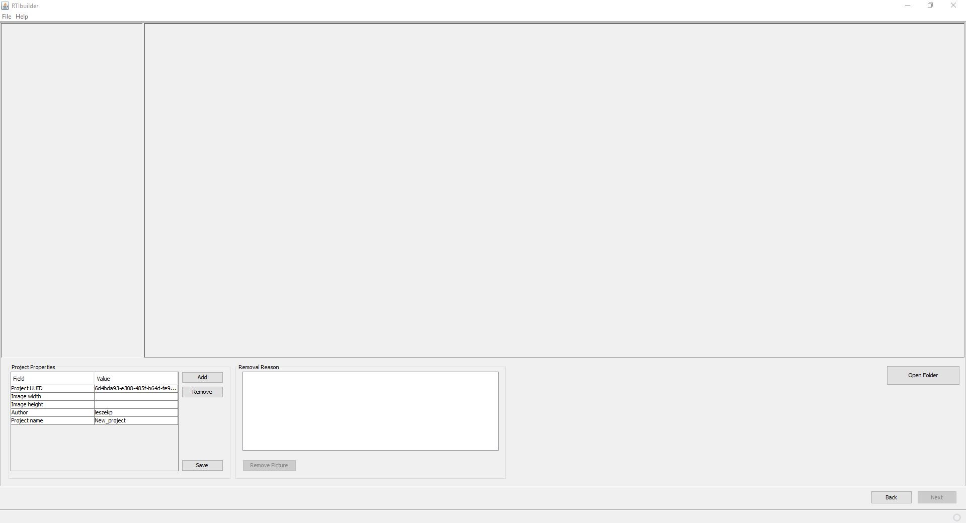
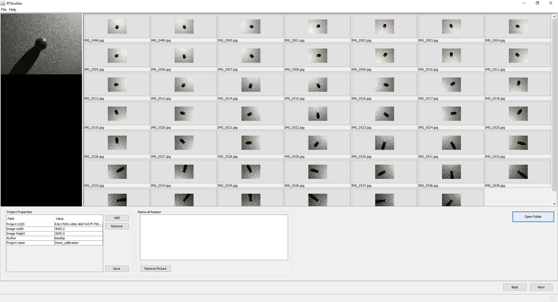
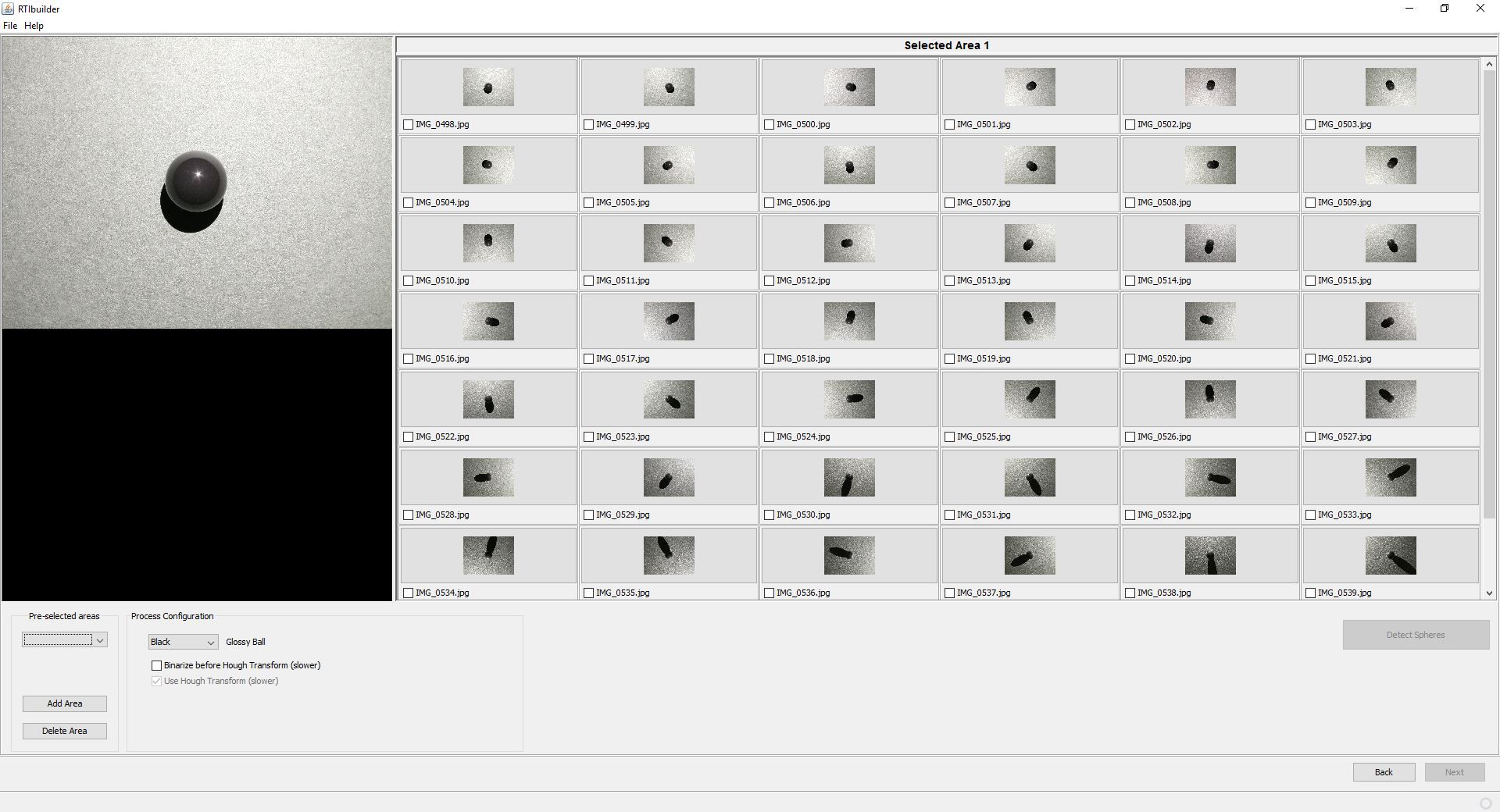
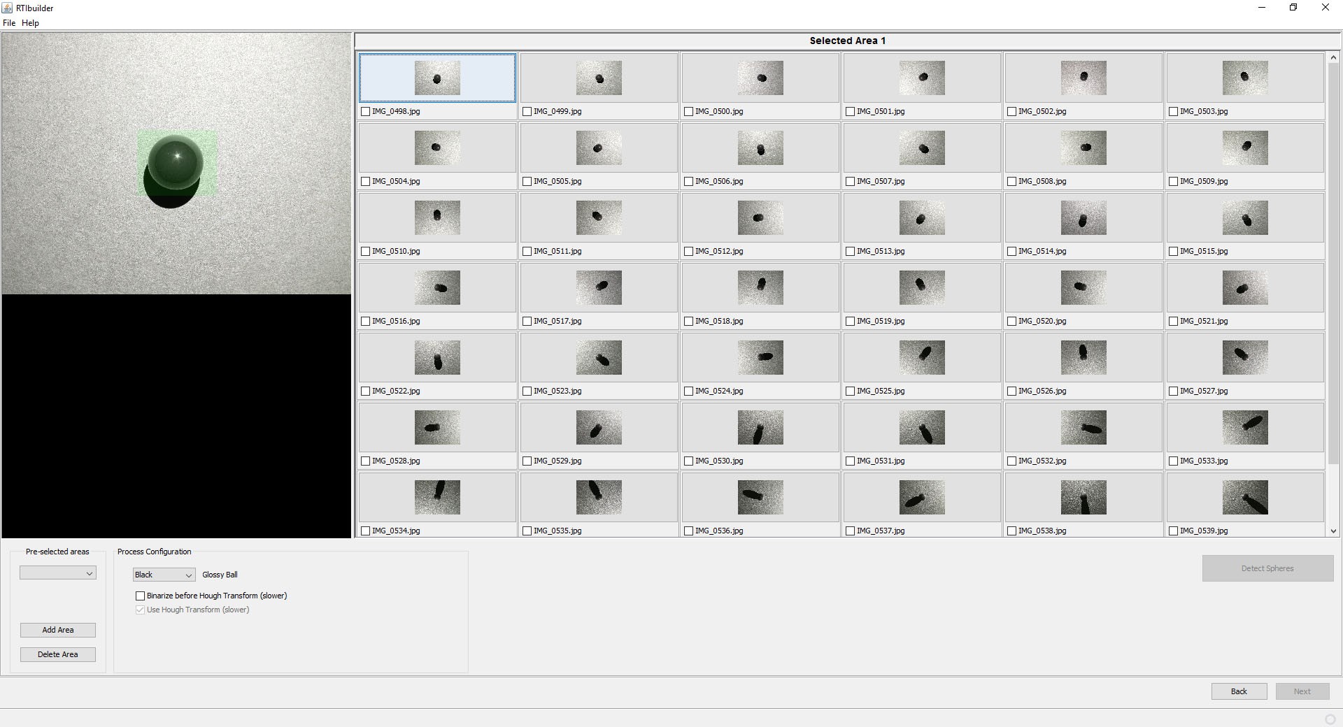
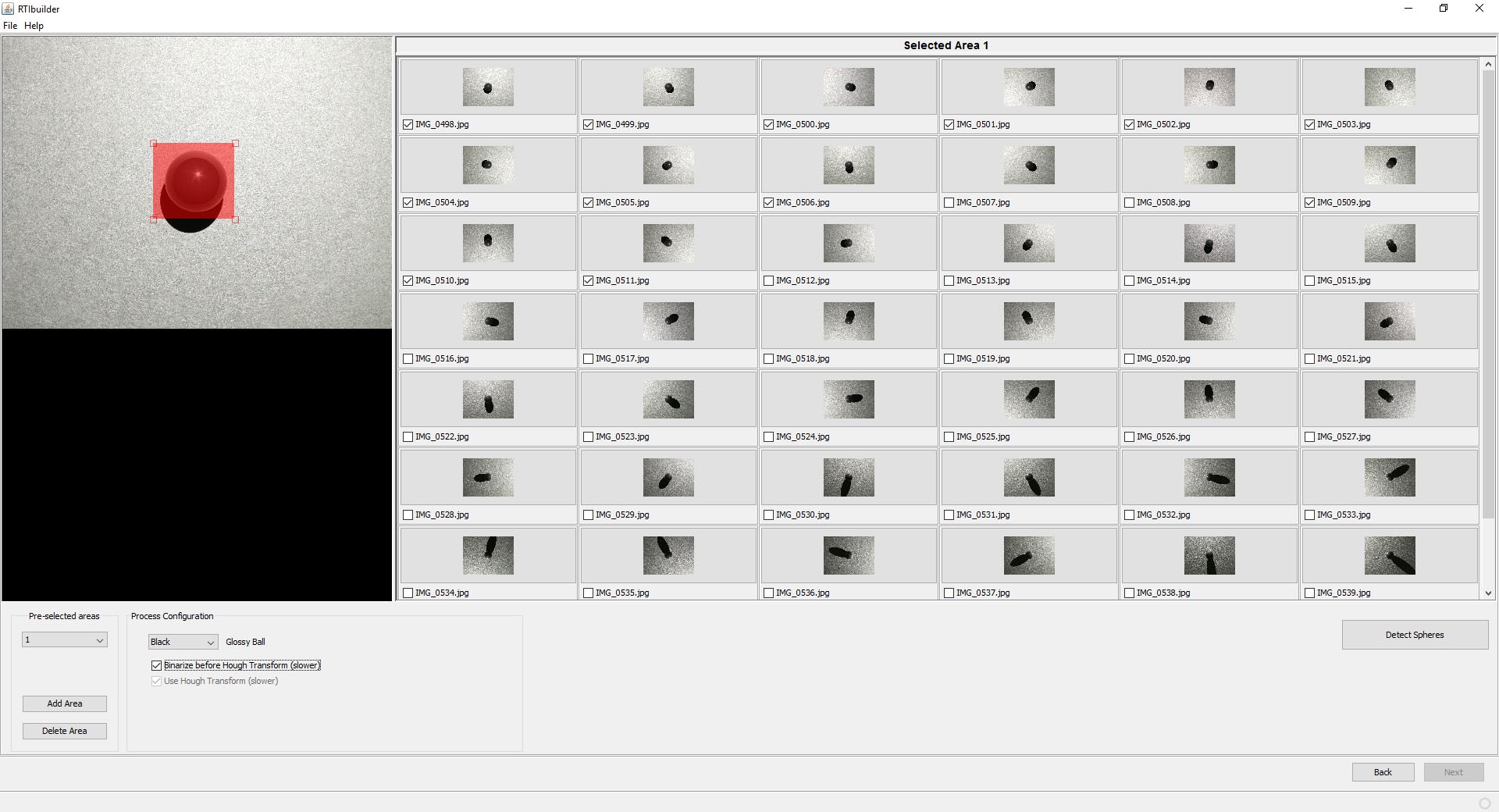
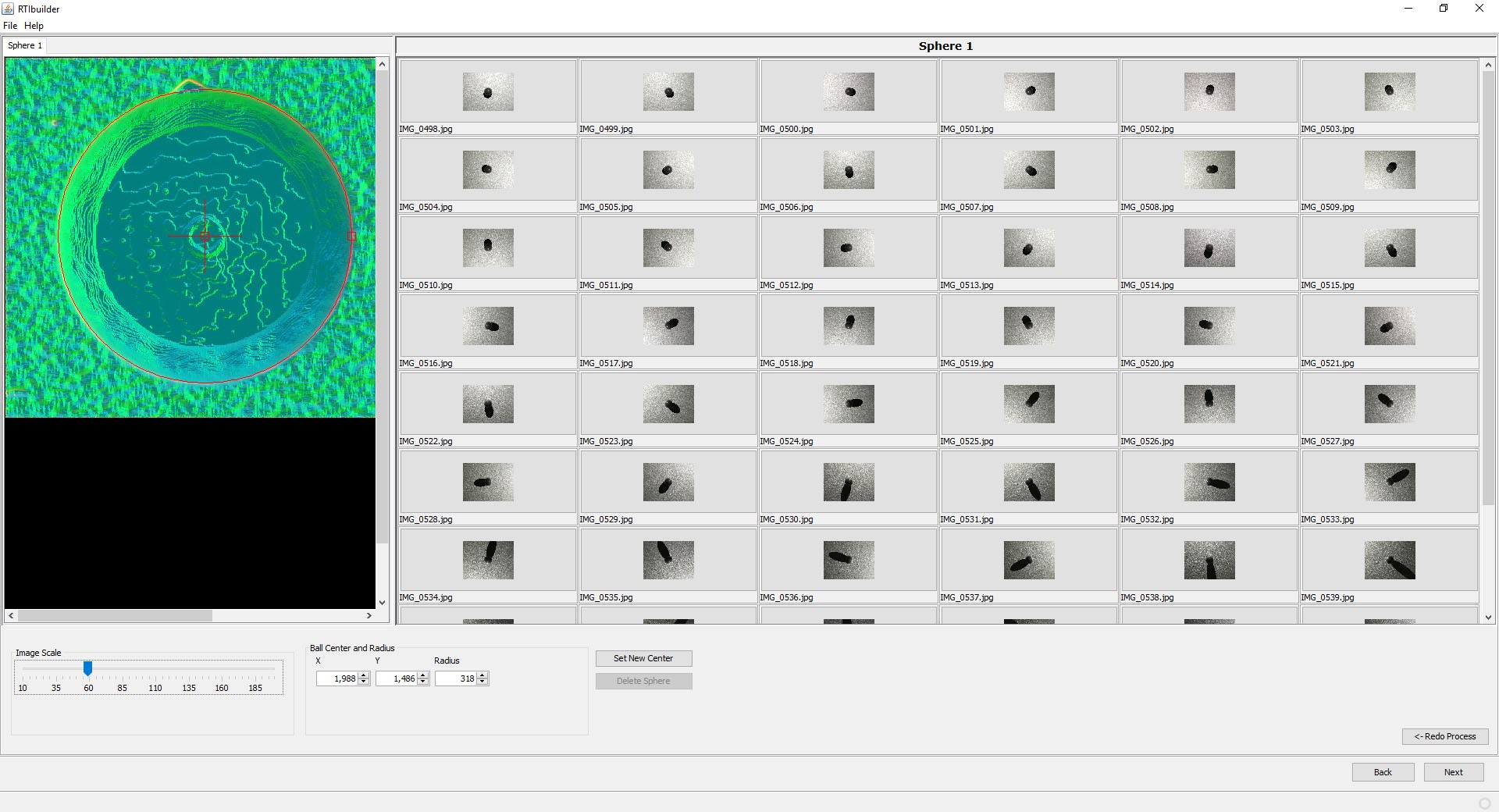
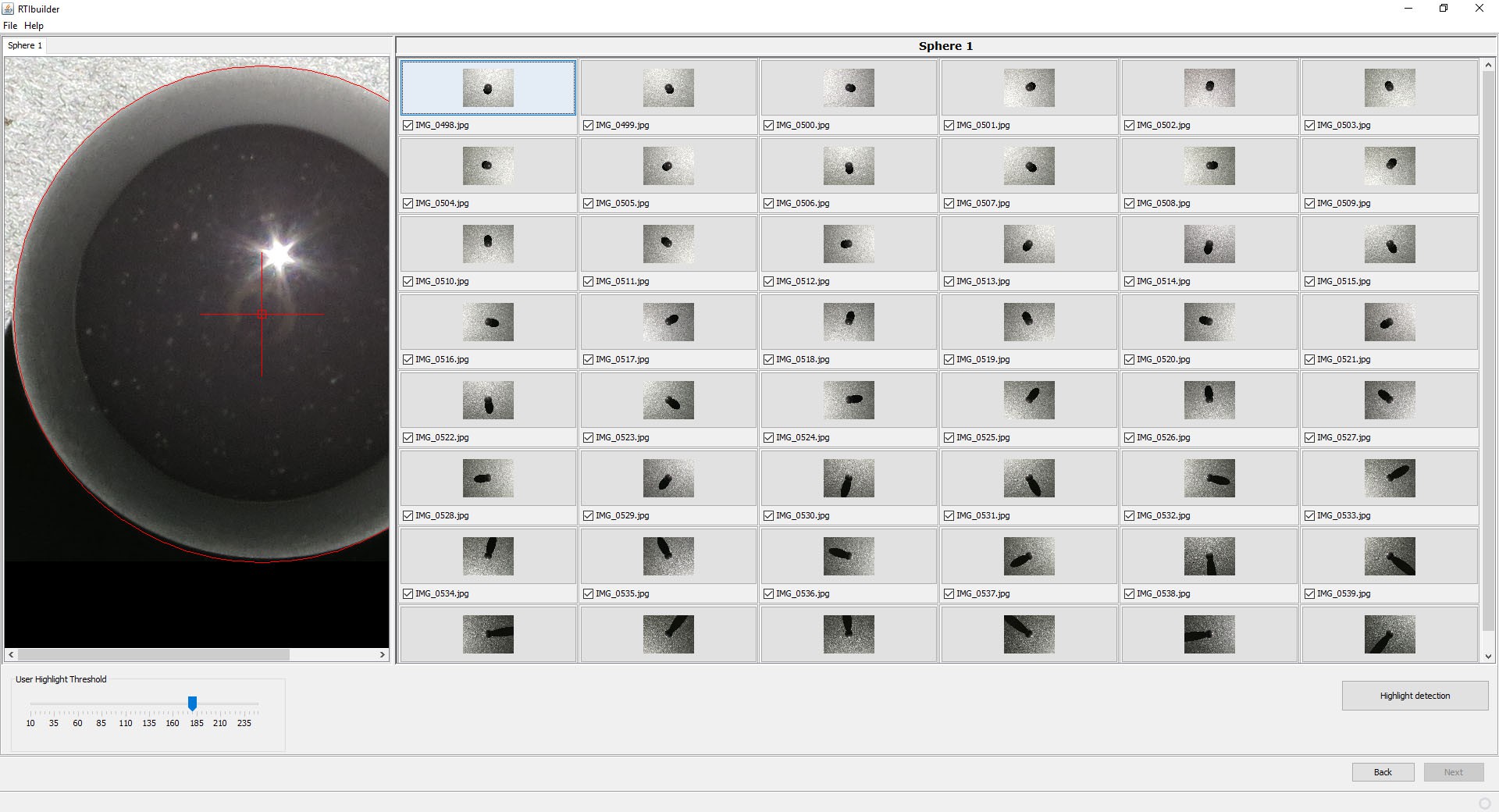

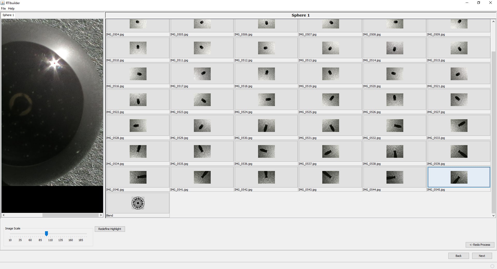
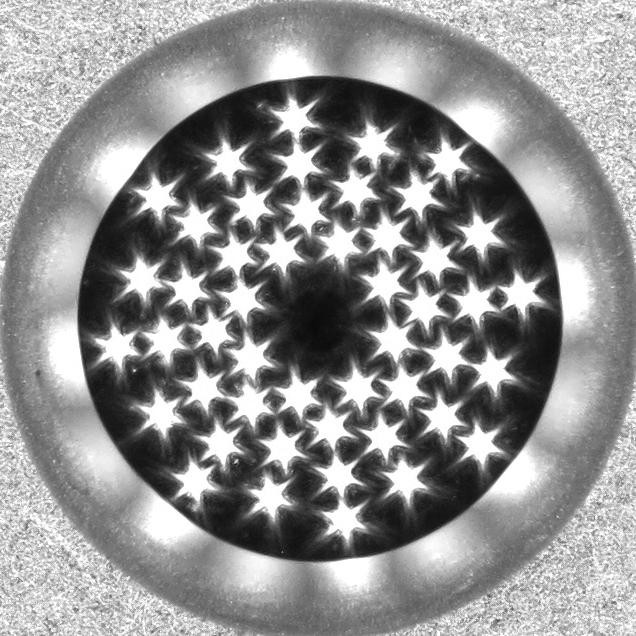
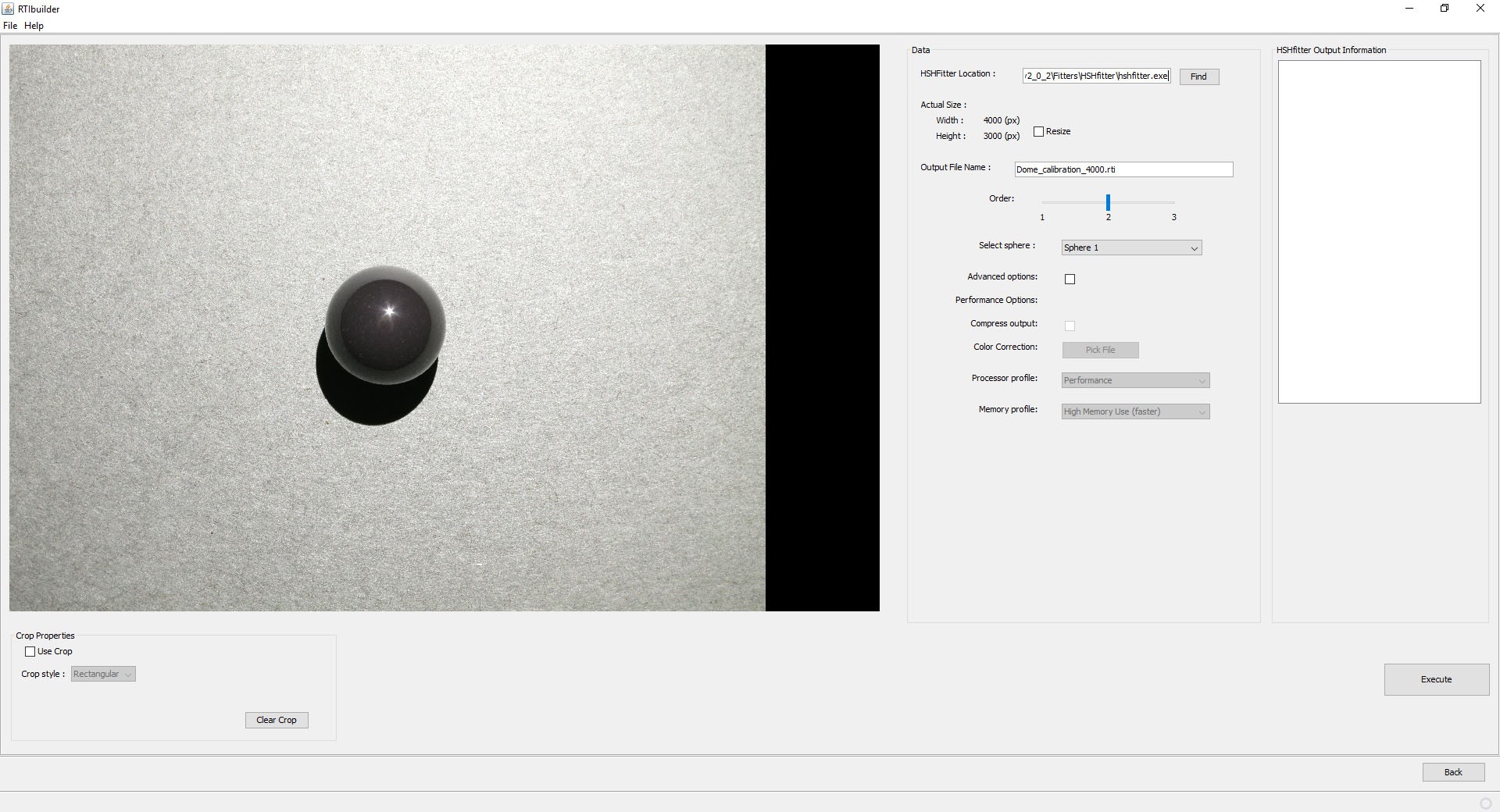
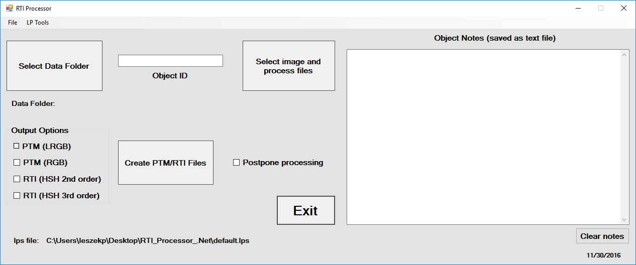

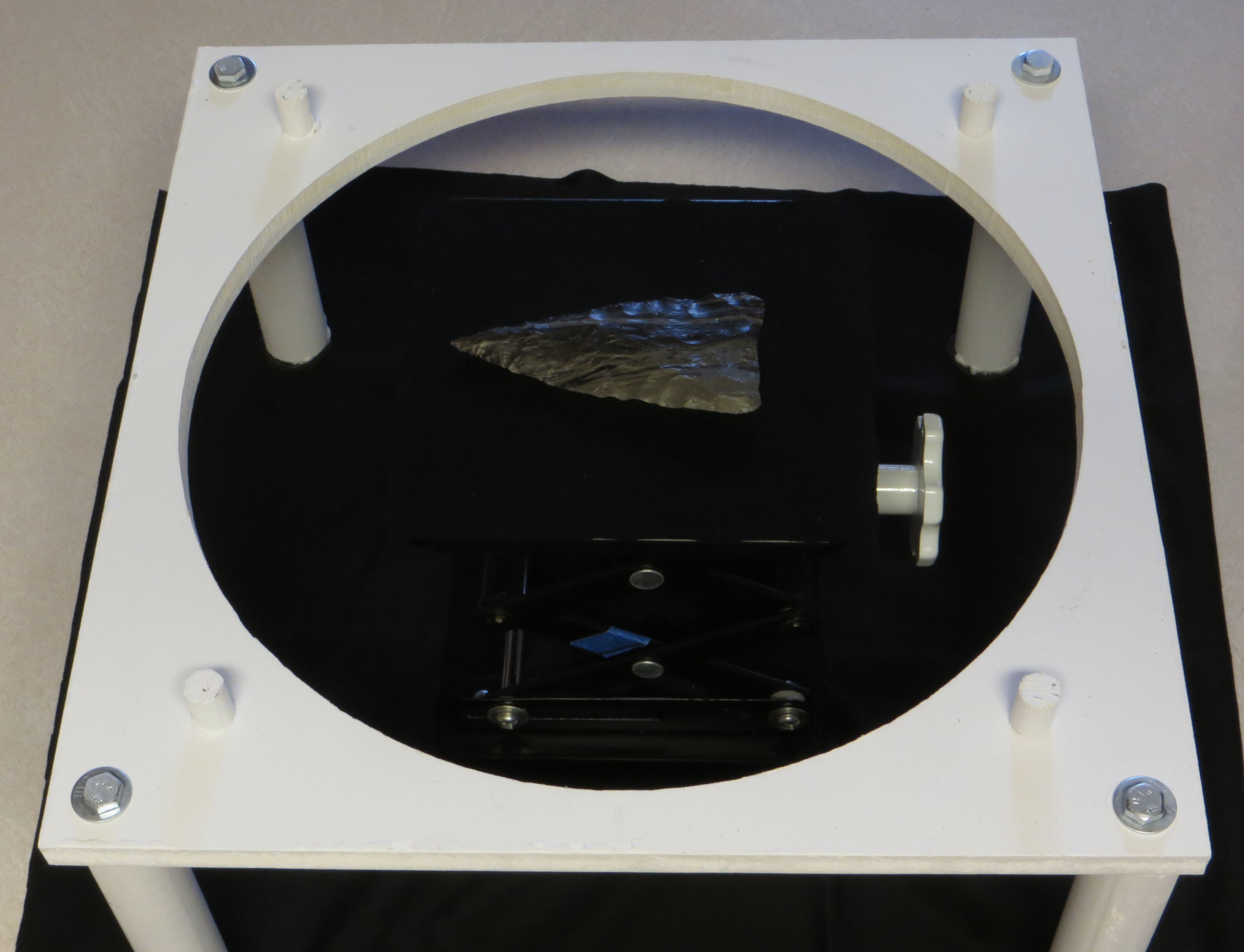

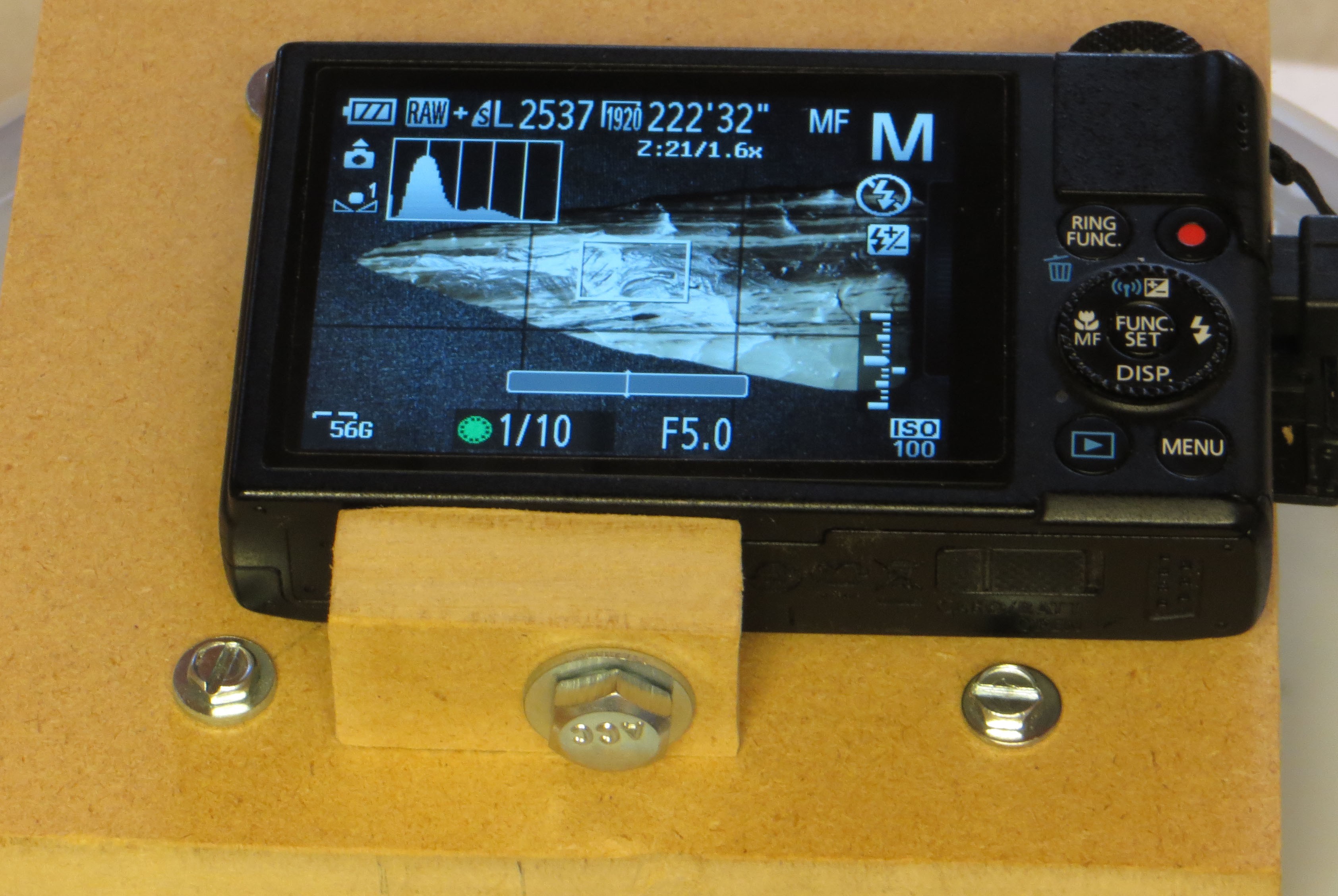
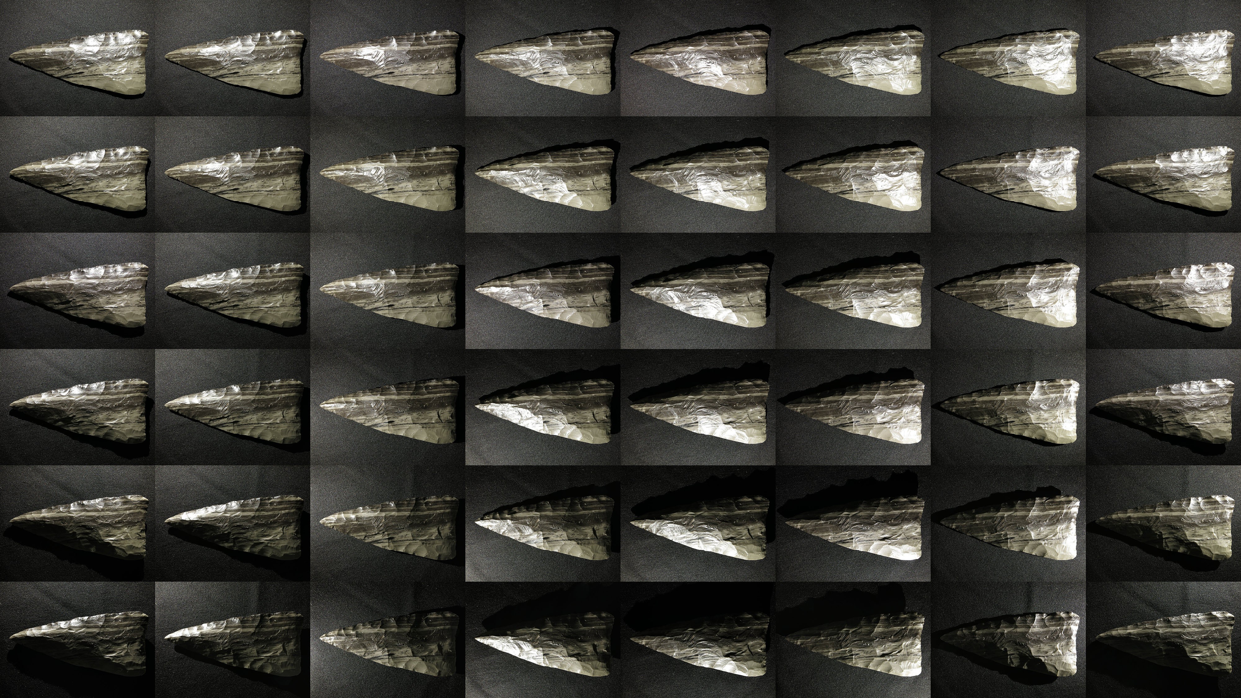

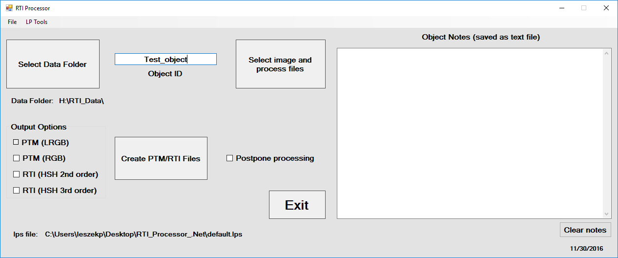
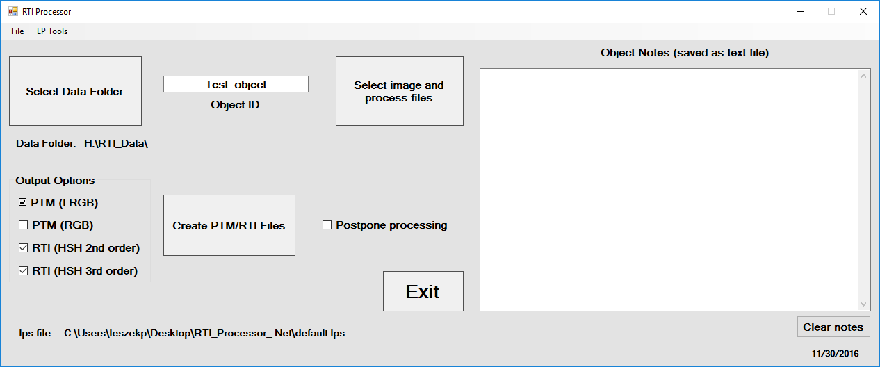

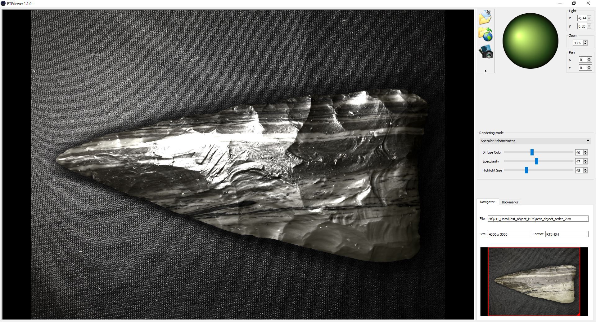
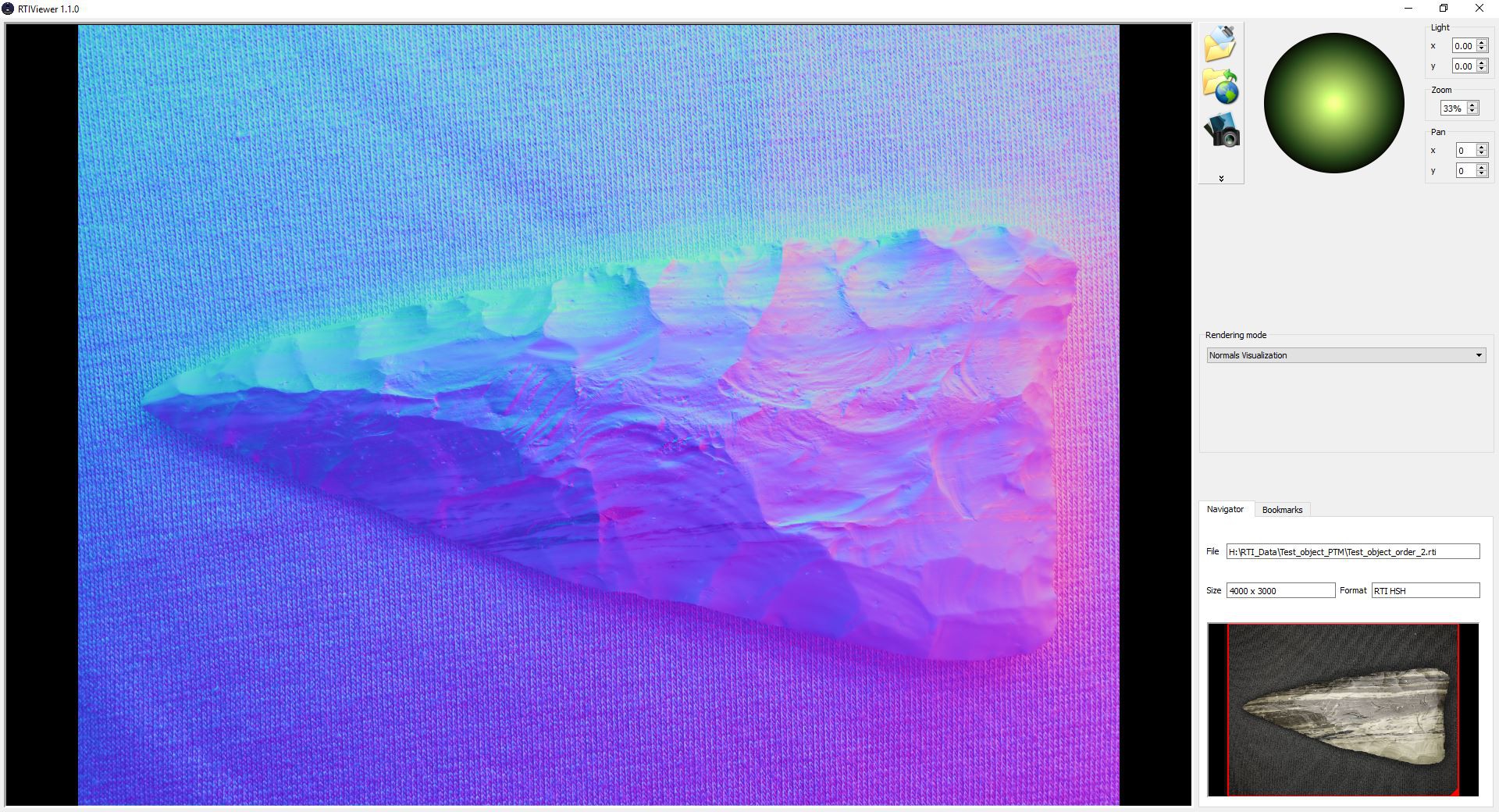
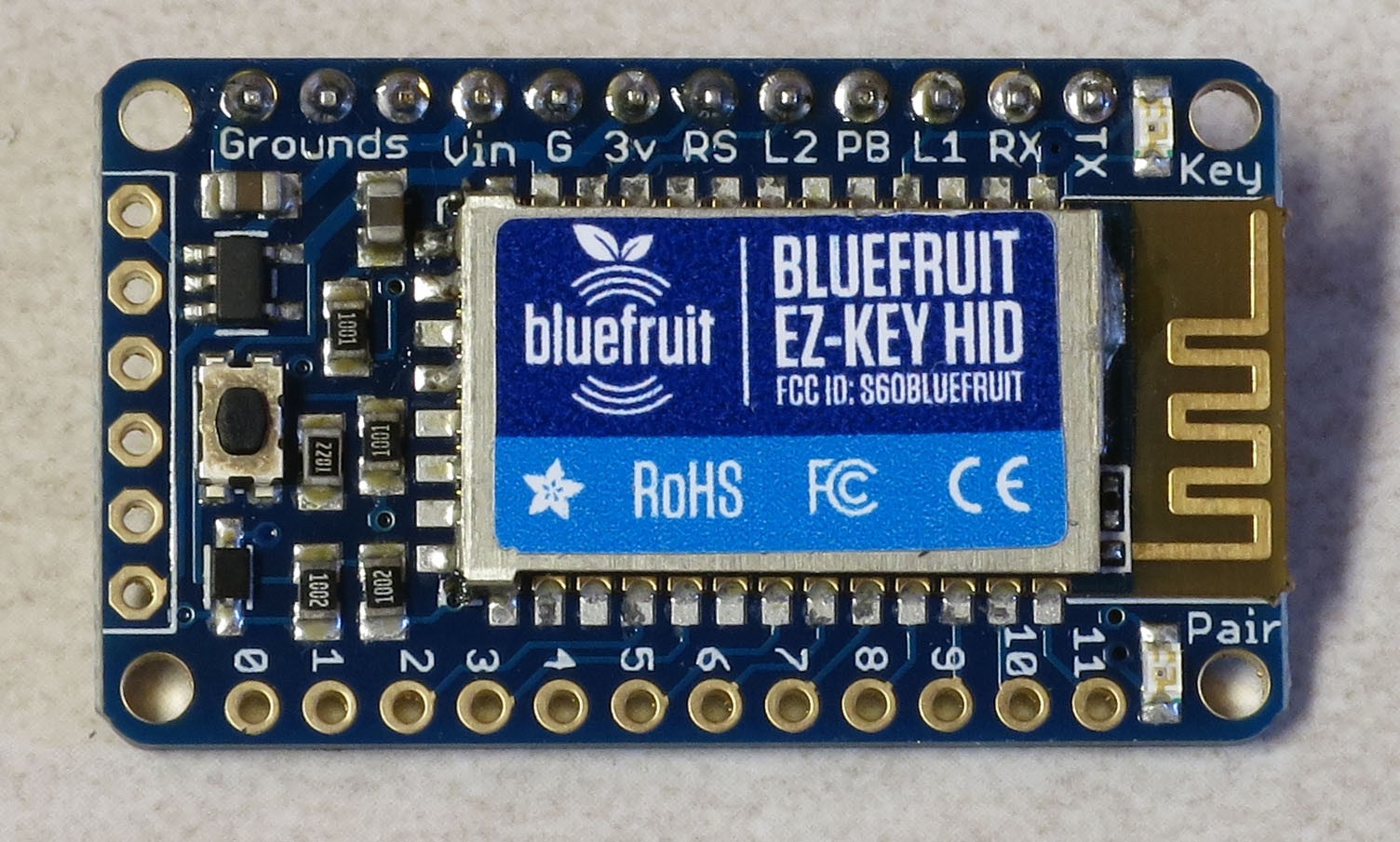
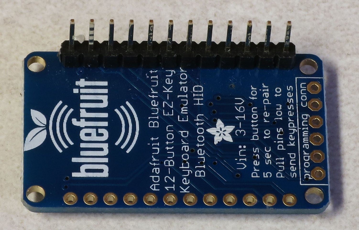
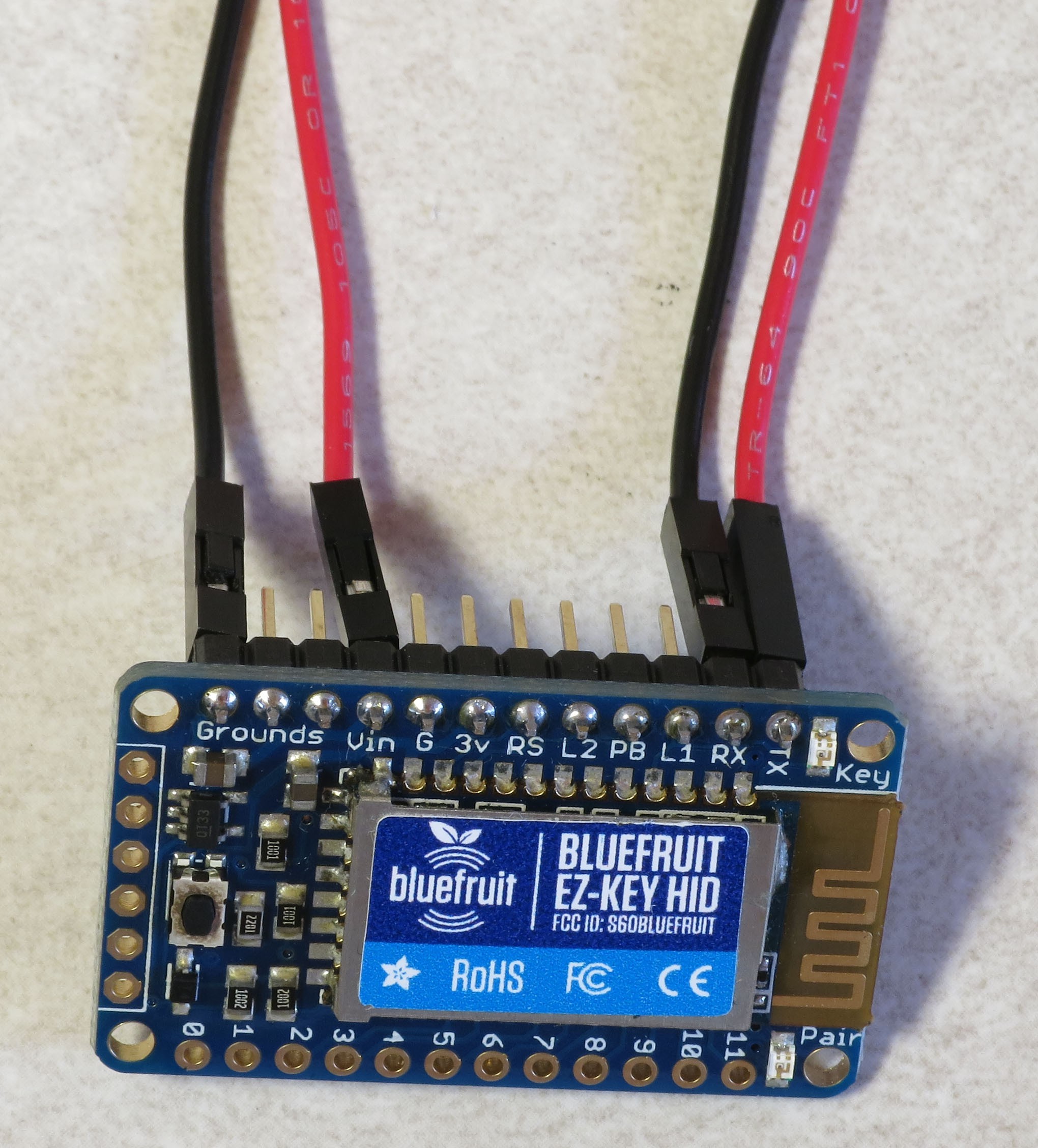
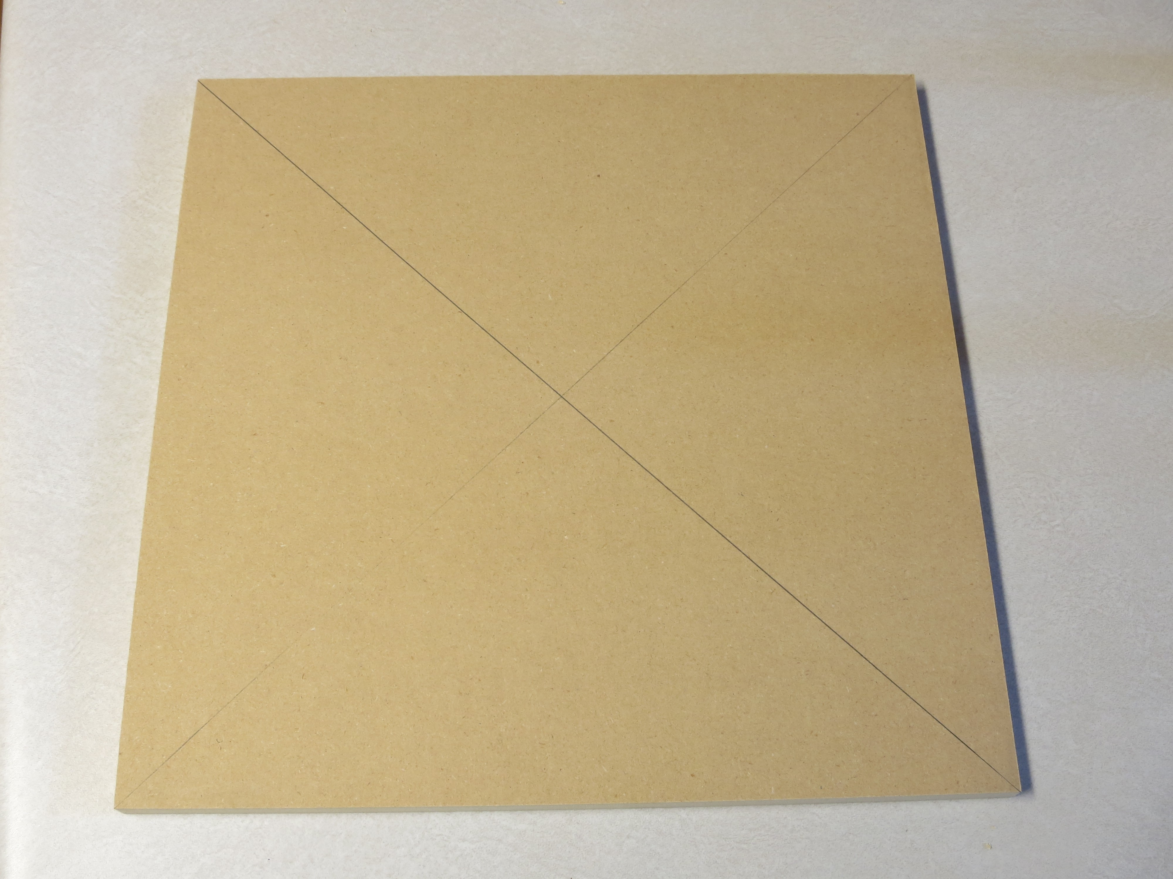
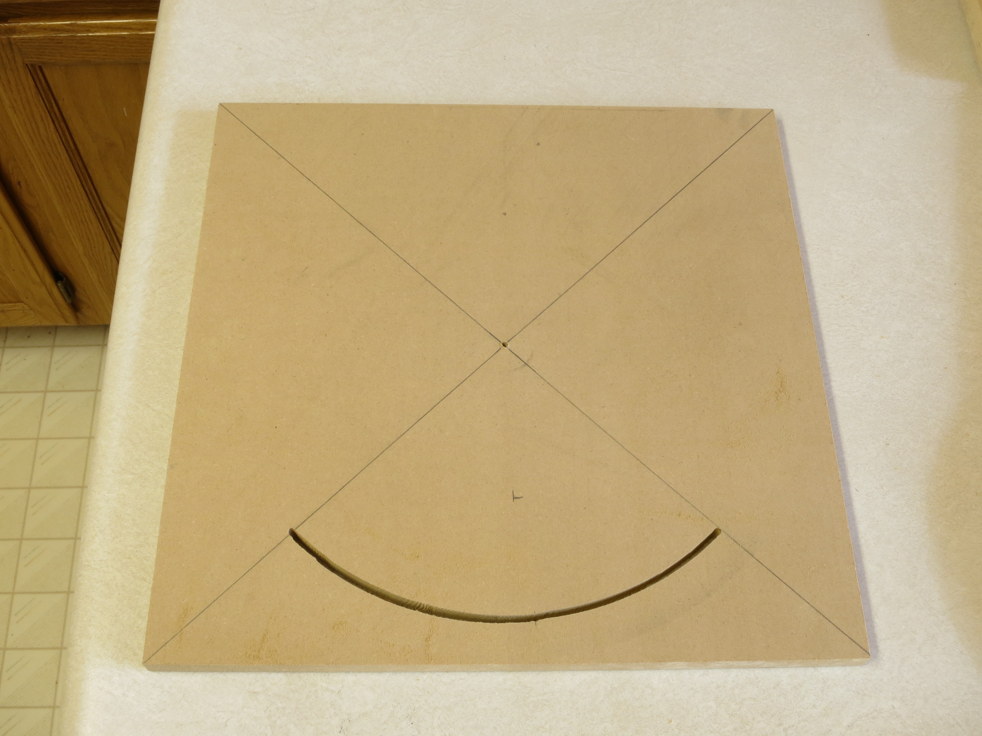
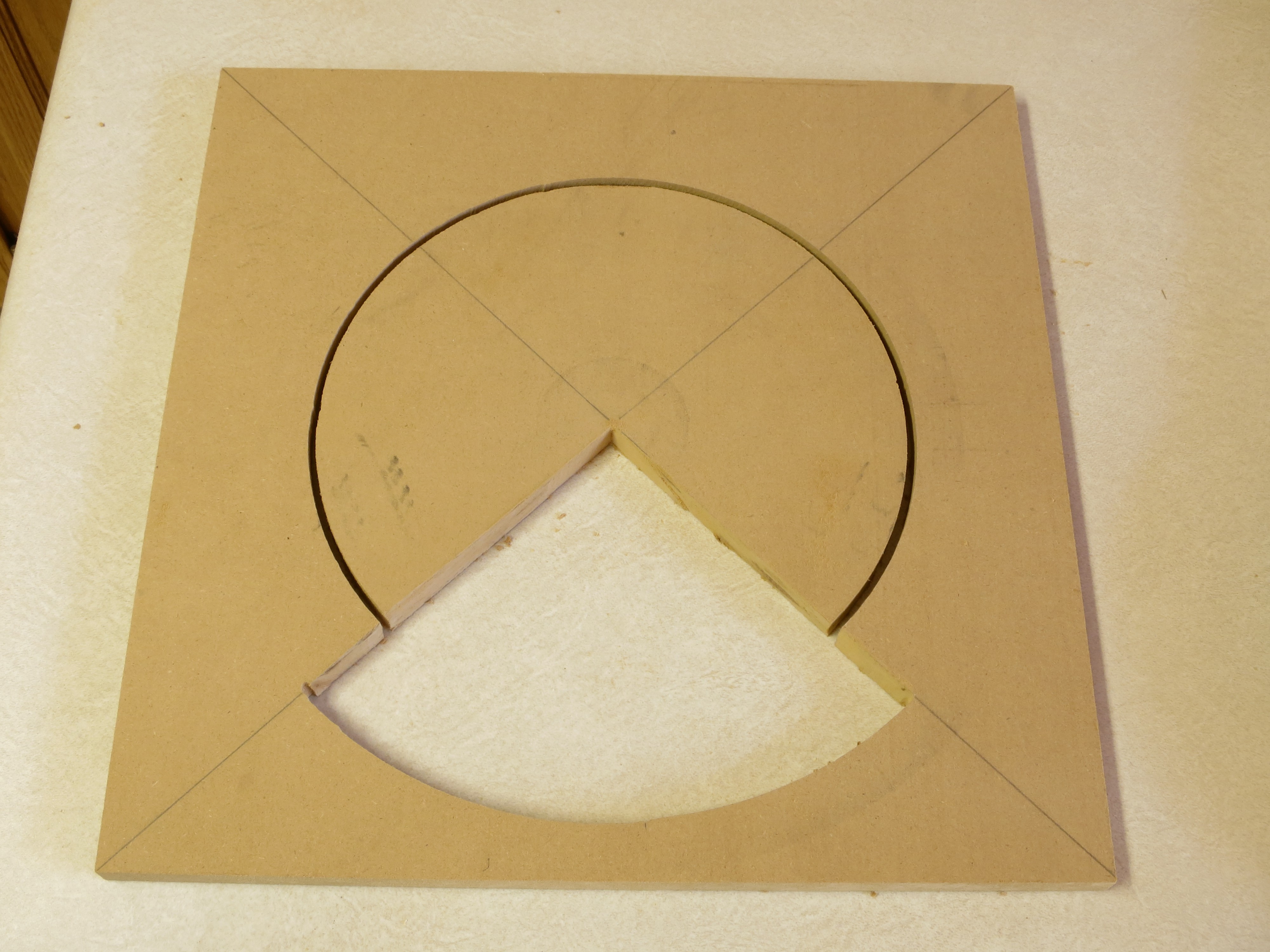

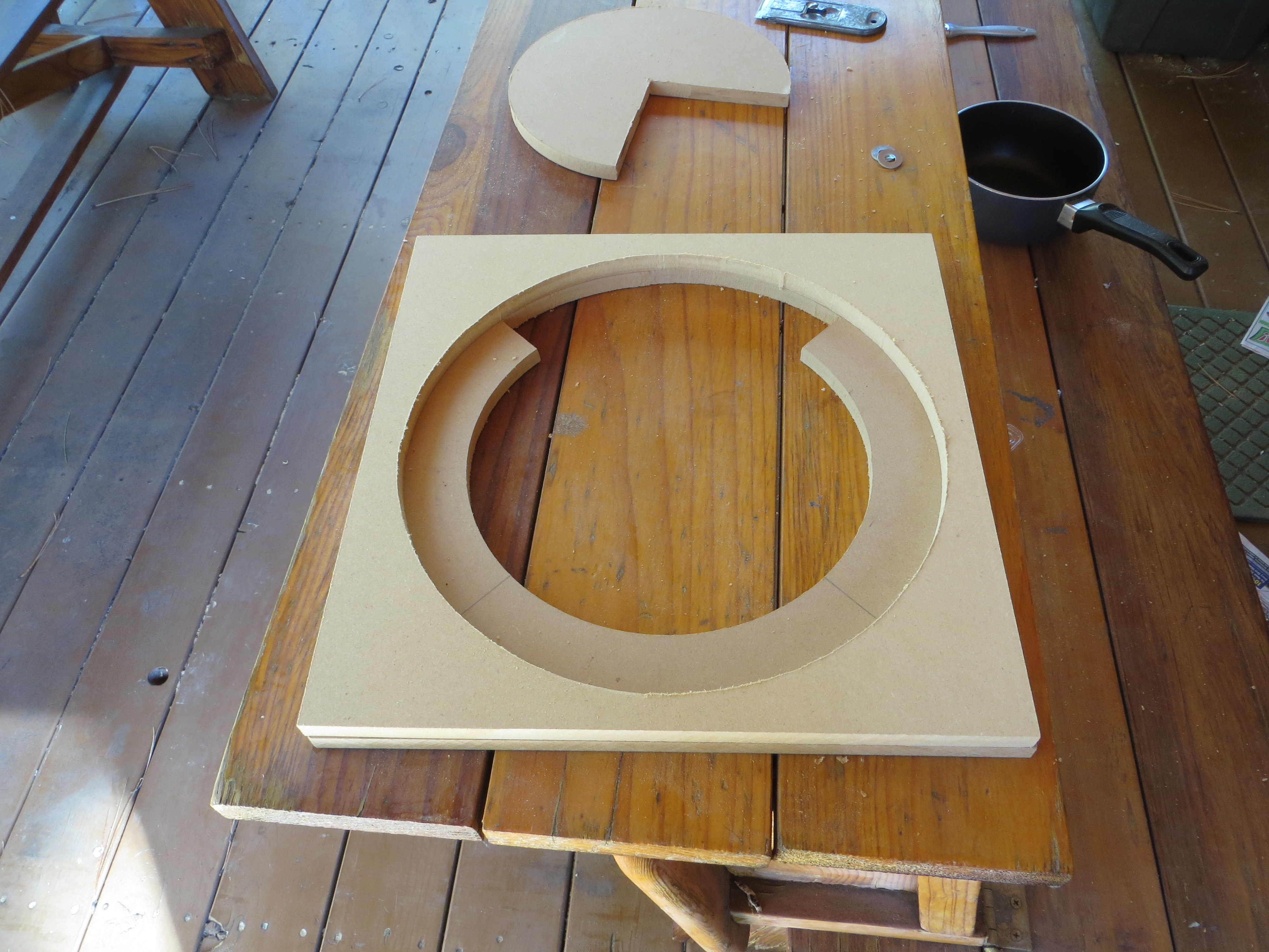

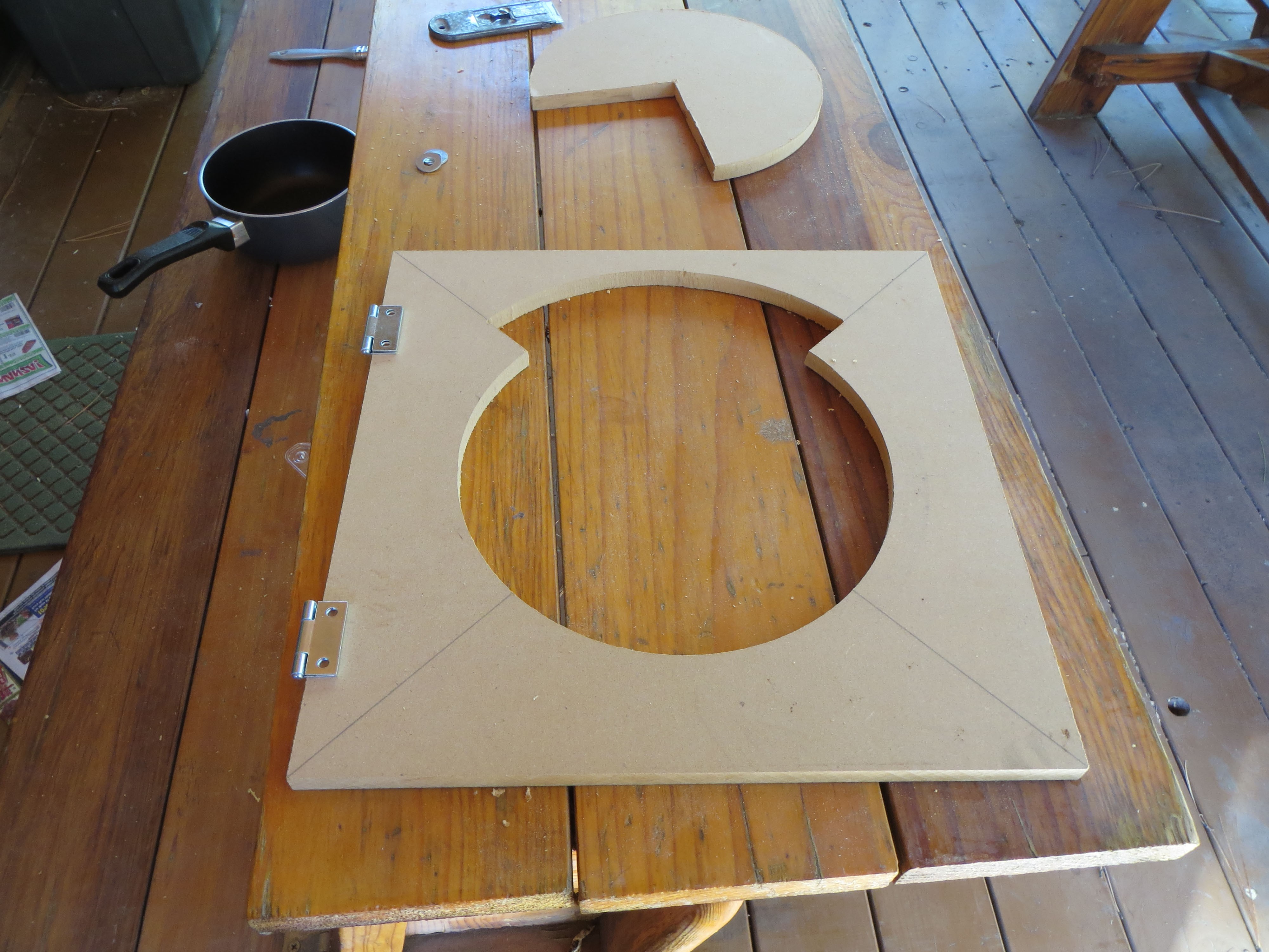
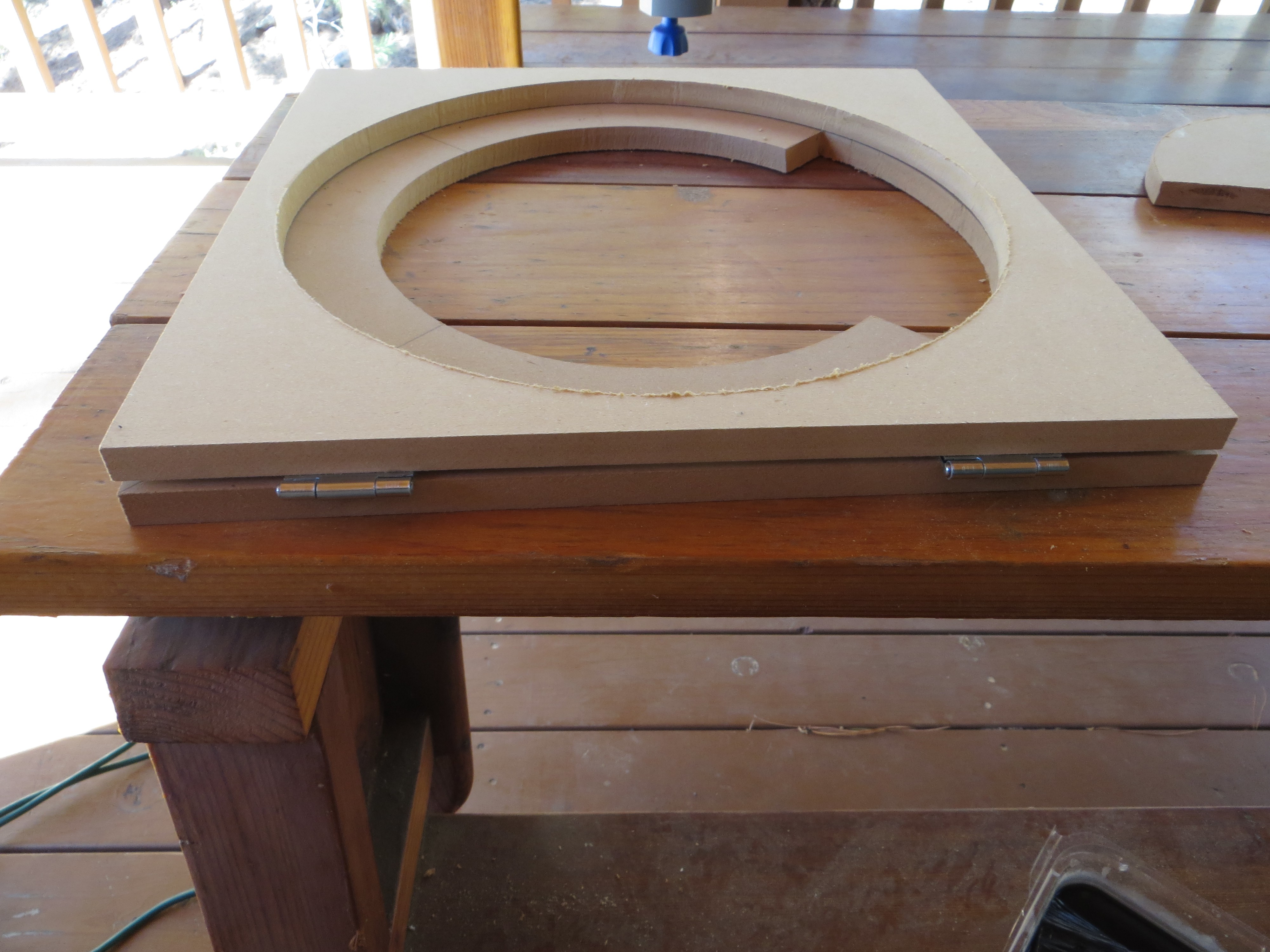
 And here’s the opposite end:
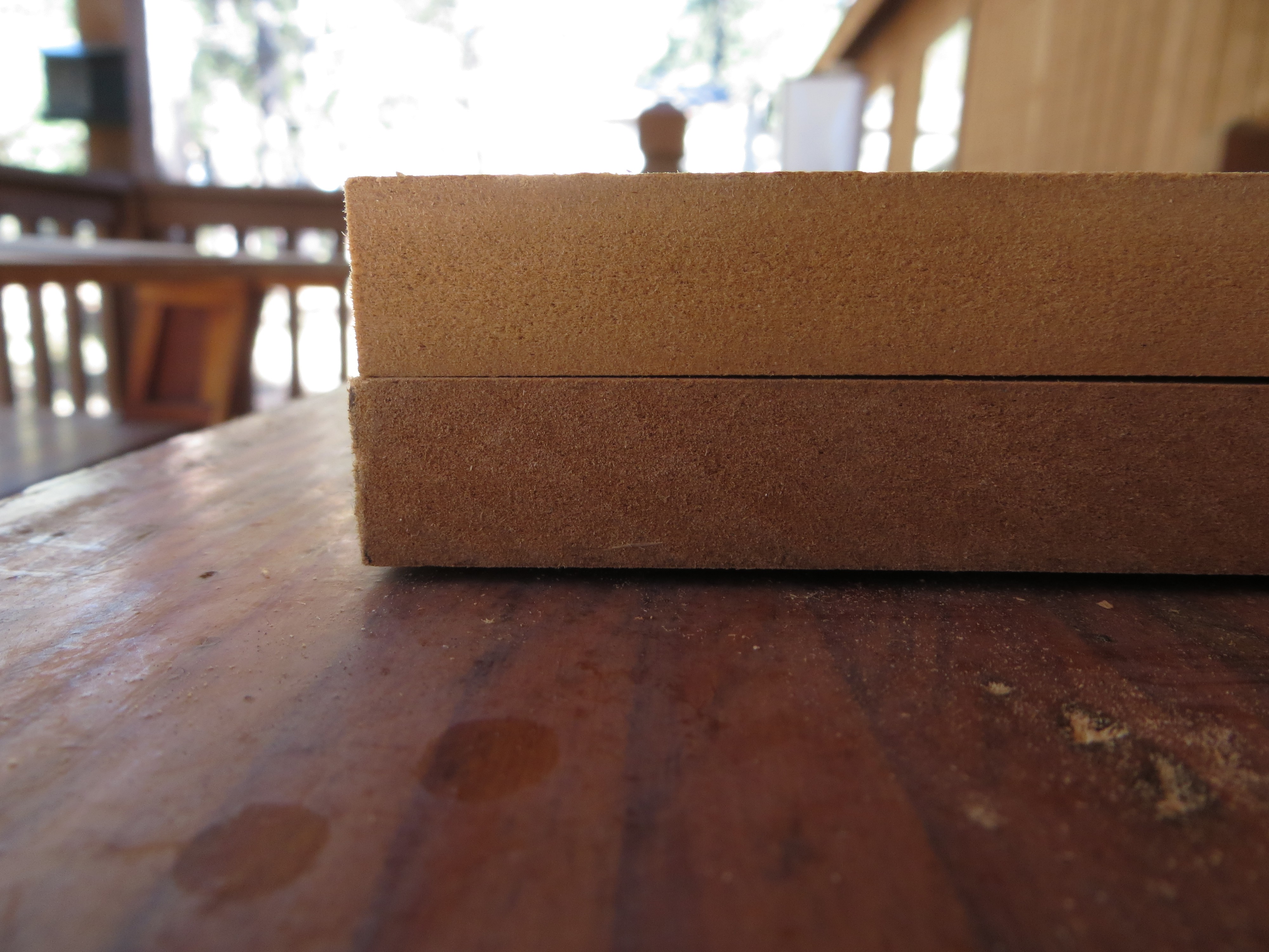
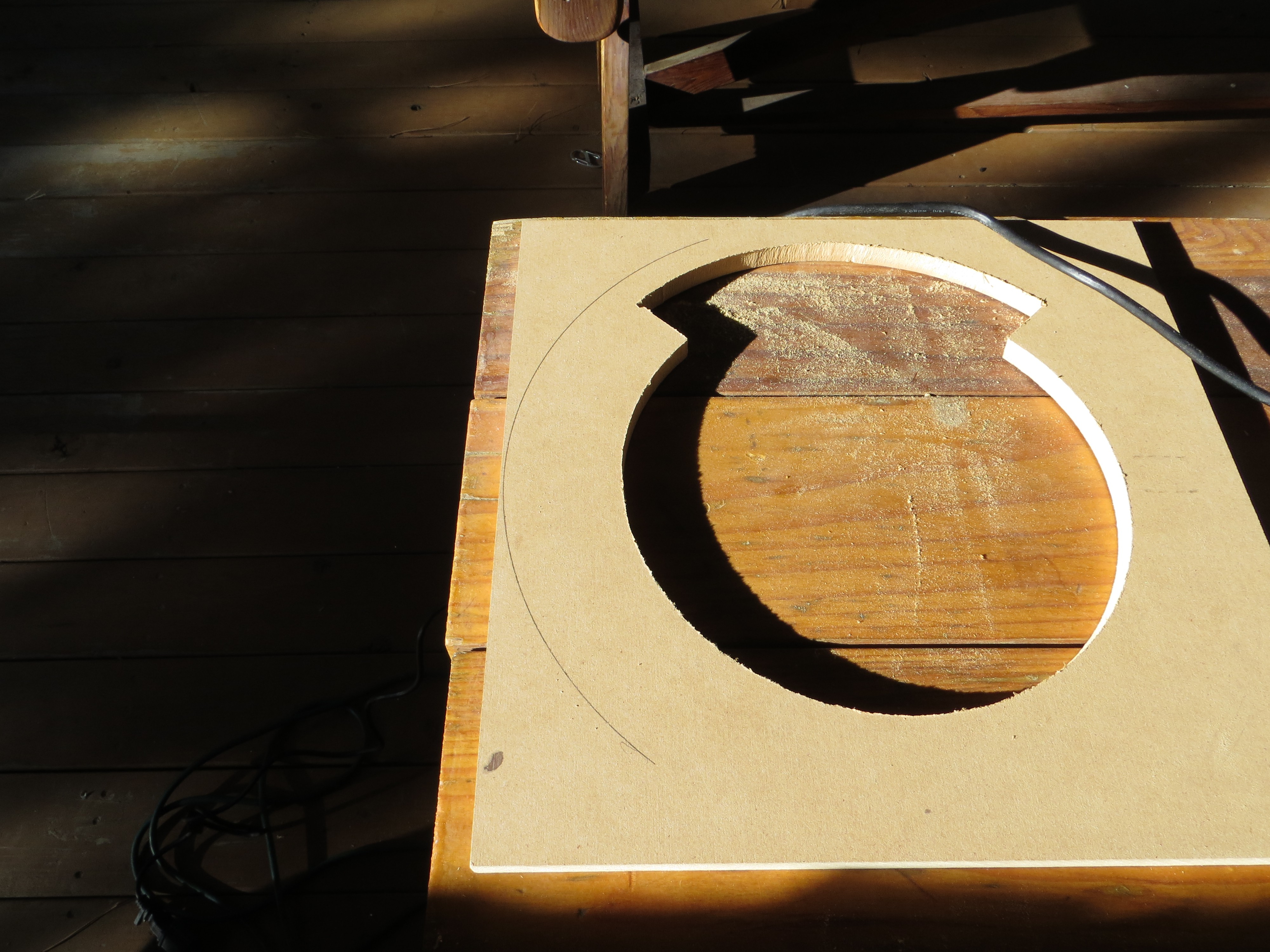
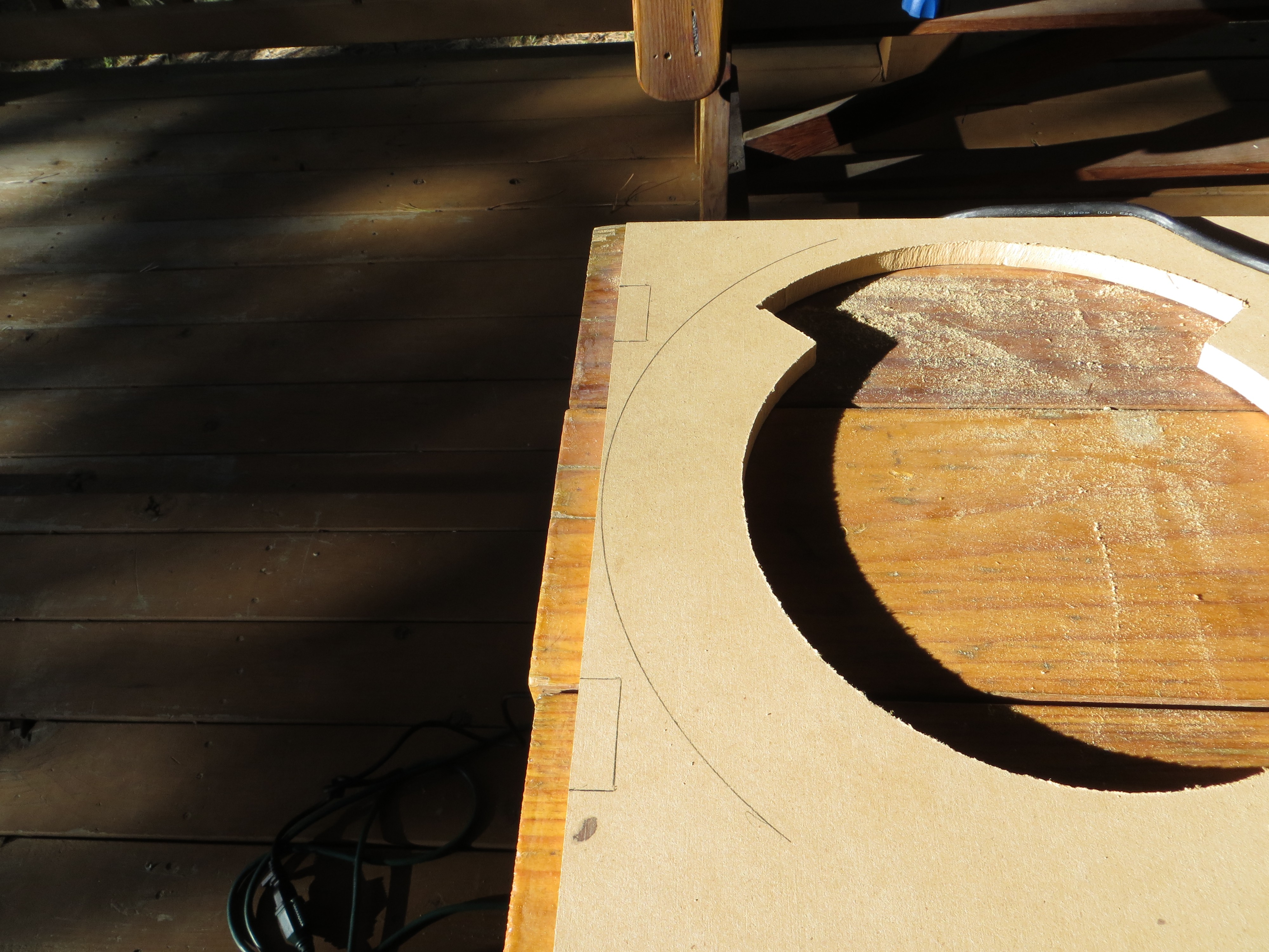
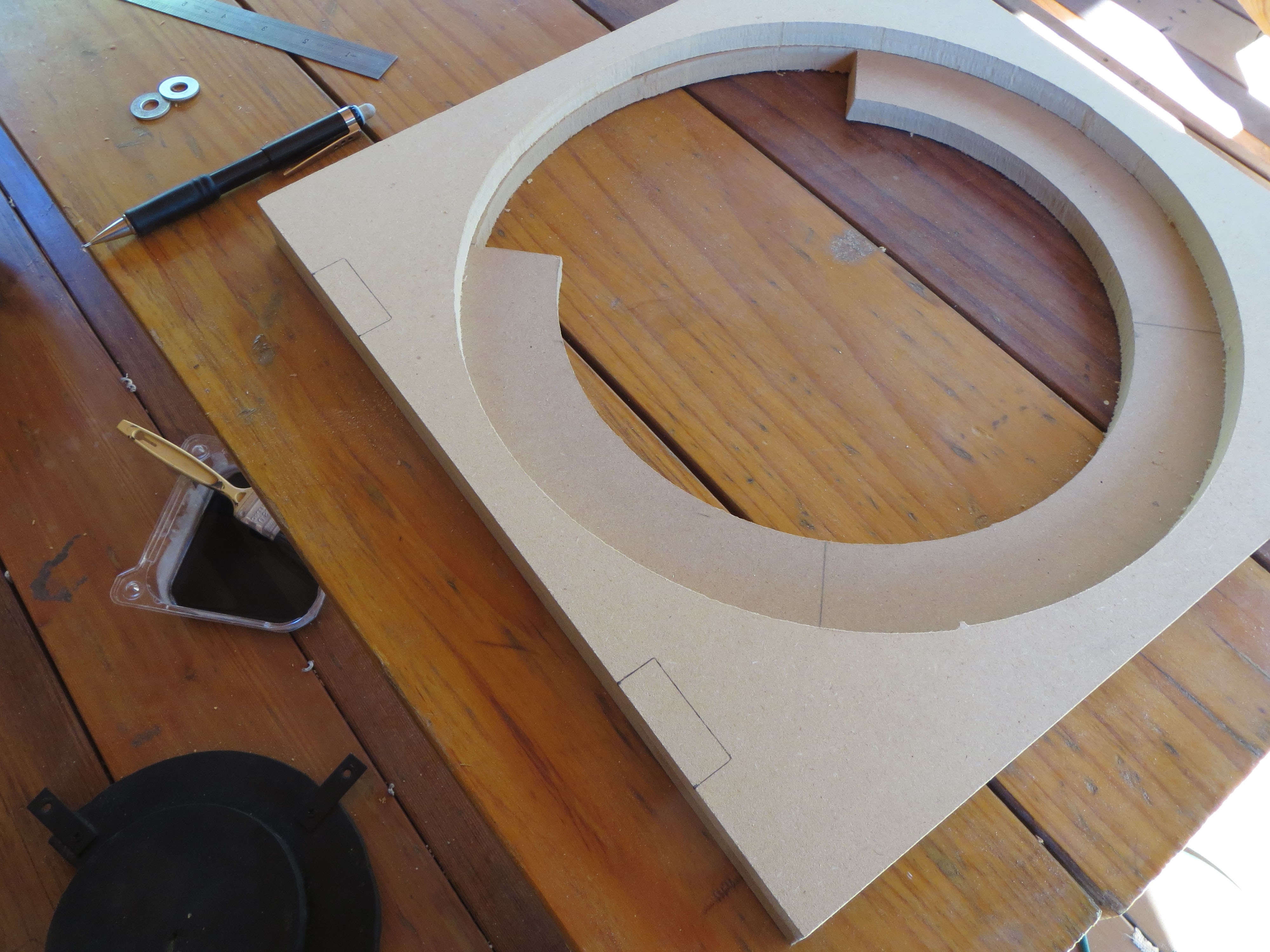
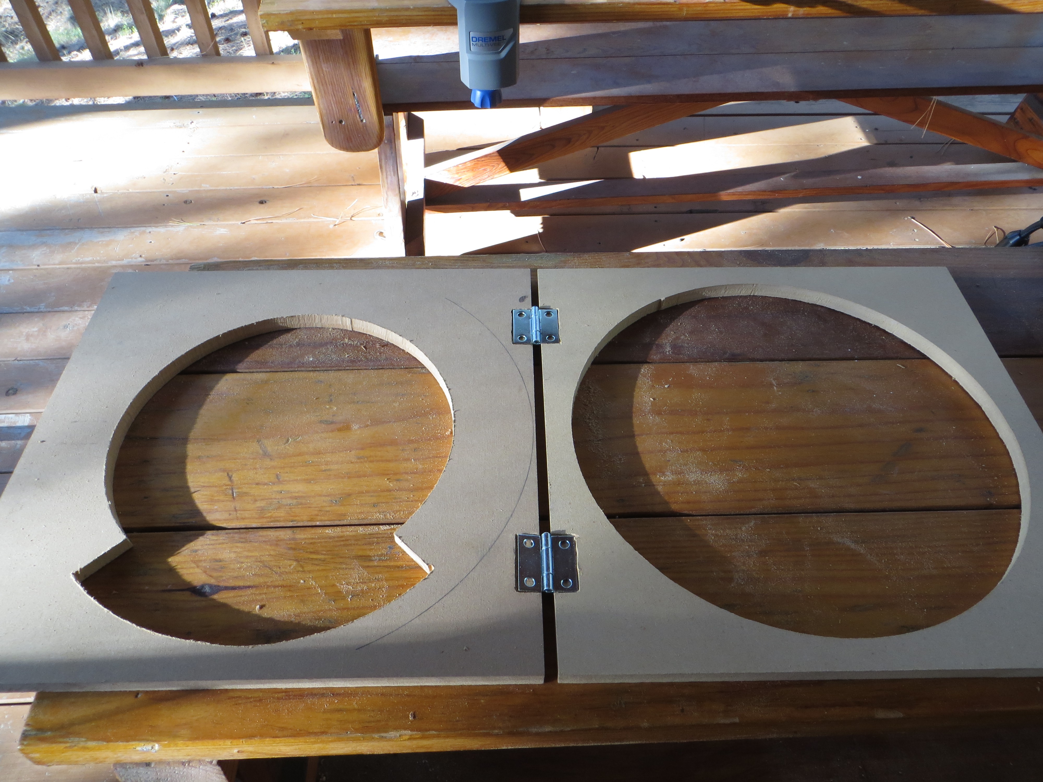
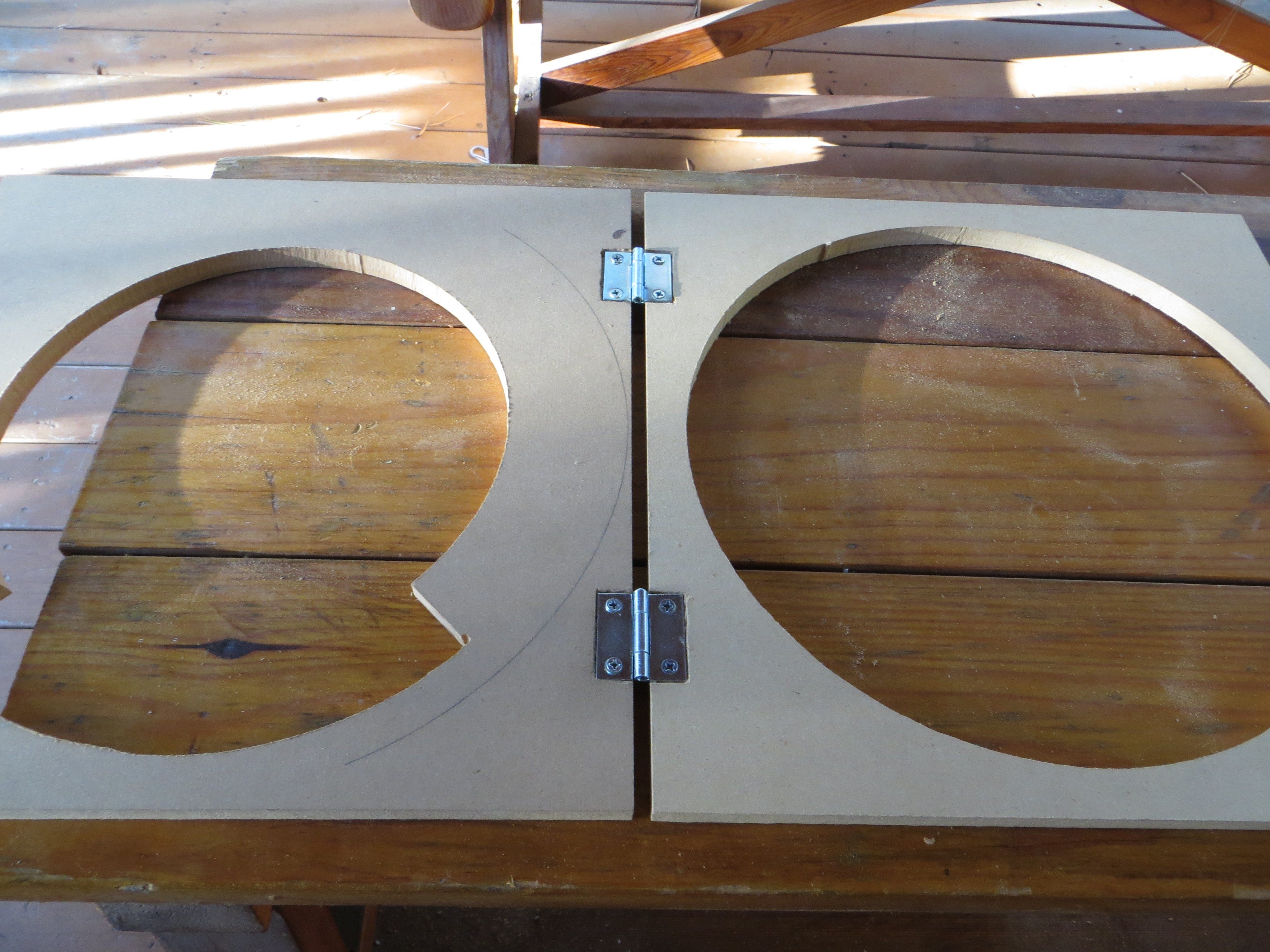
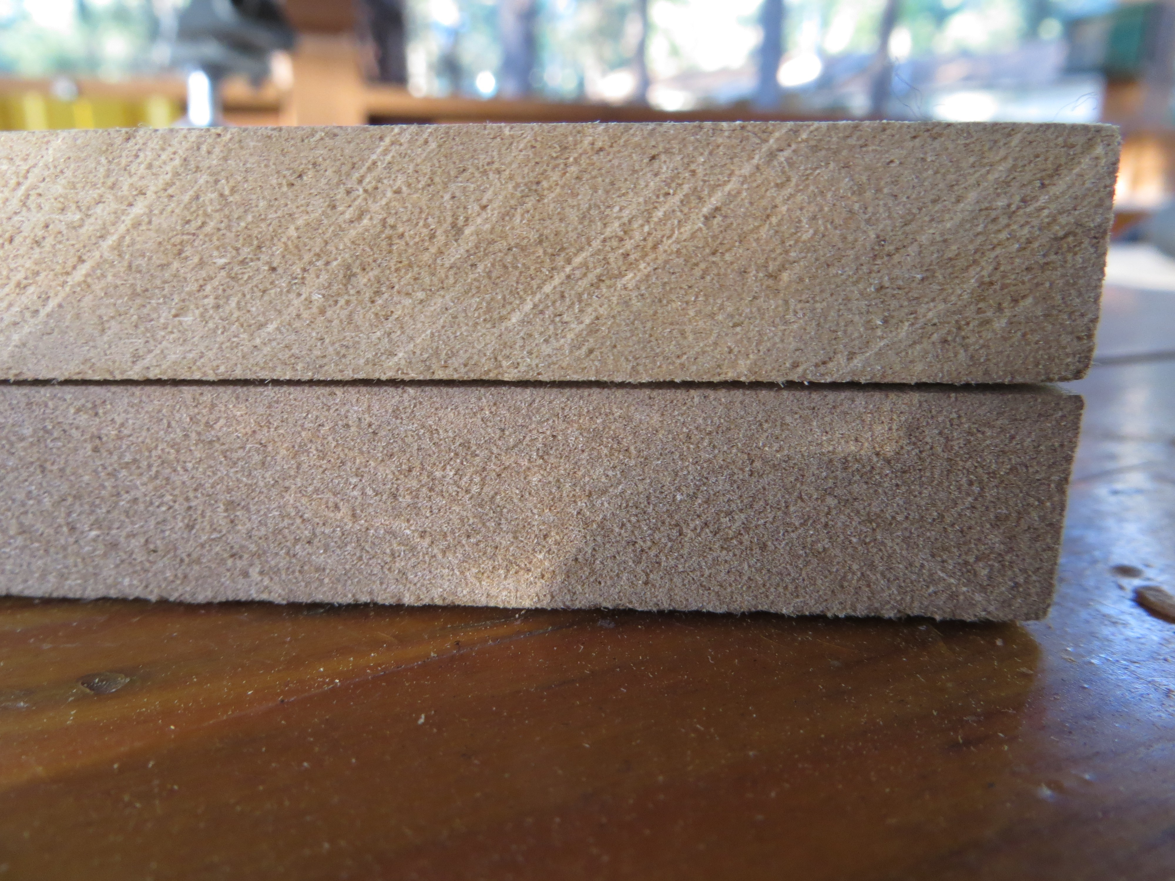

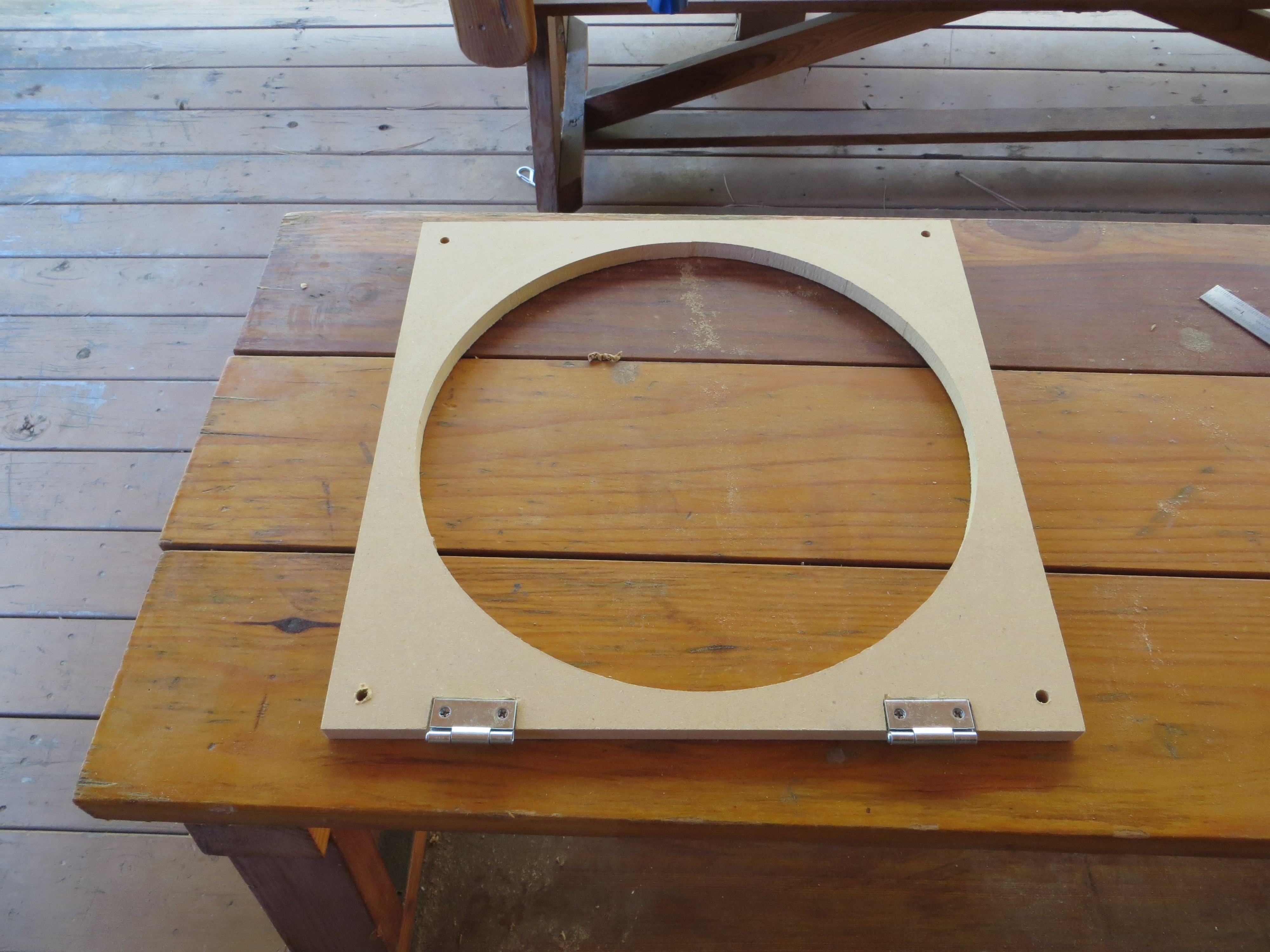
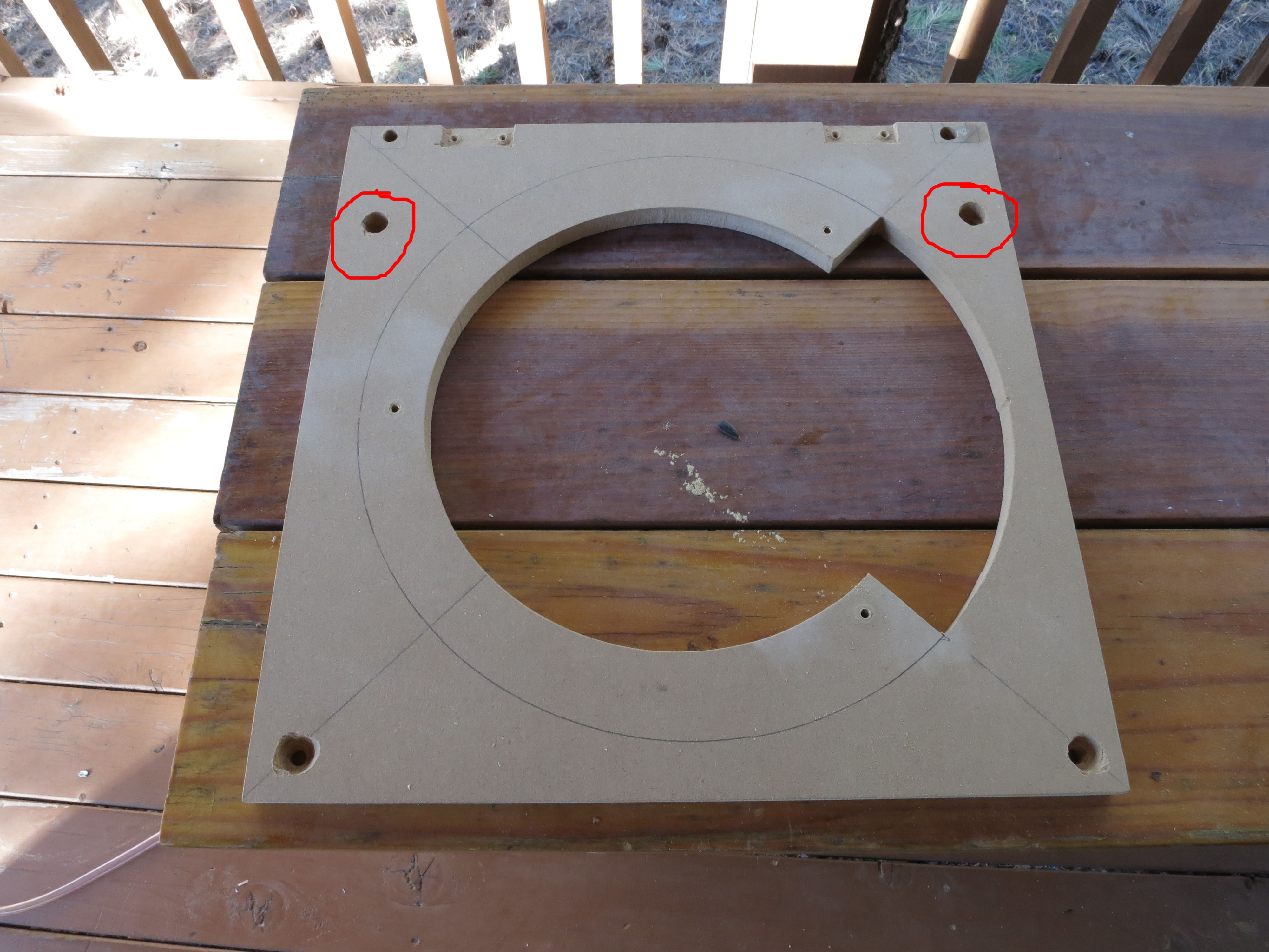
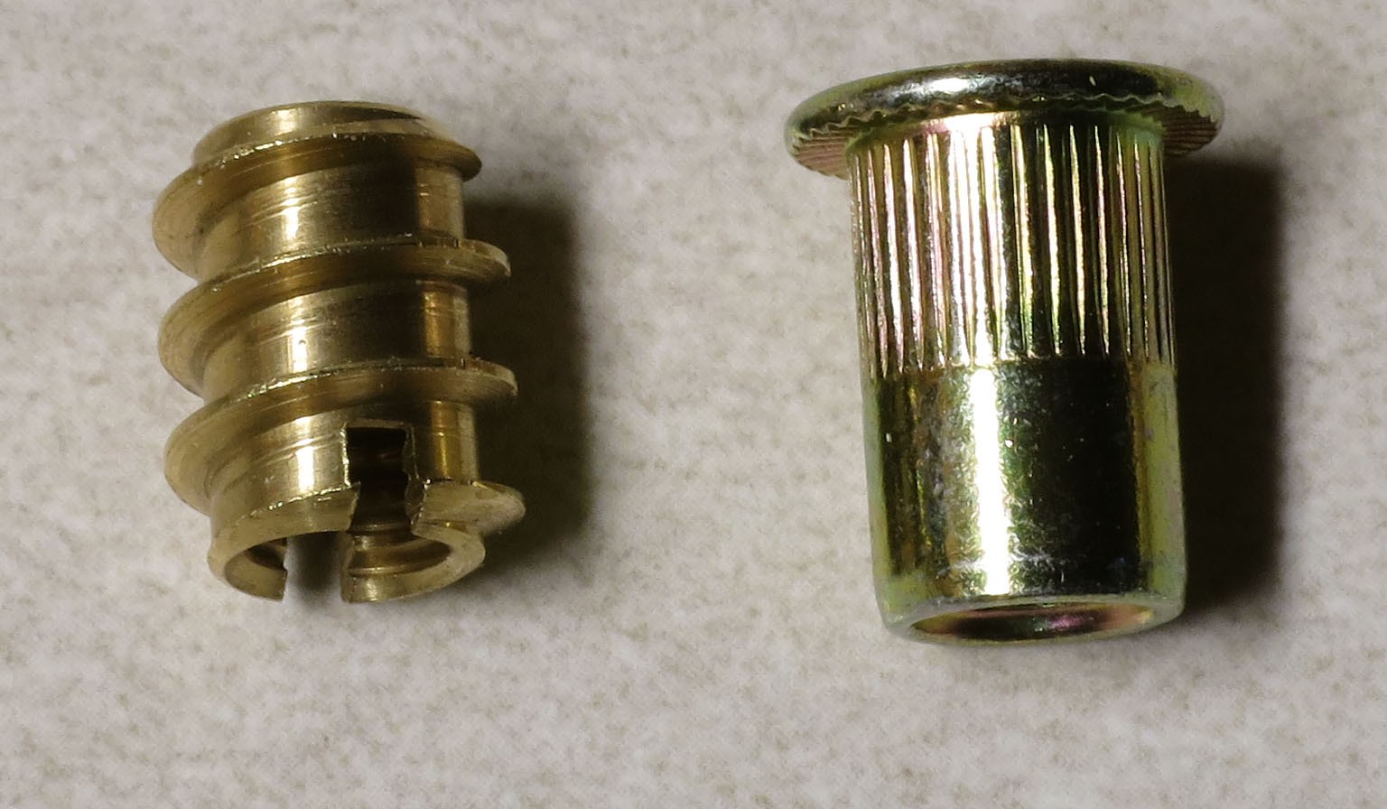
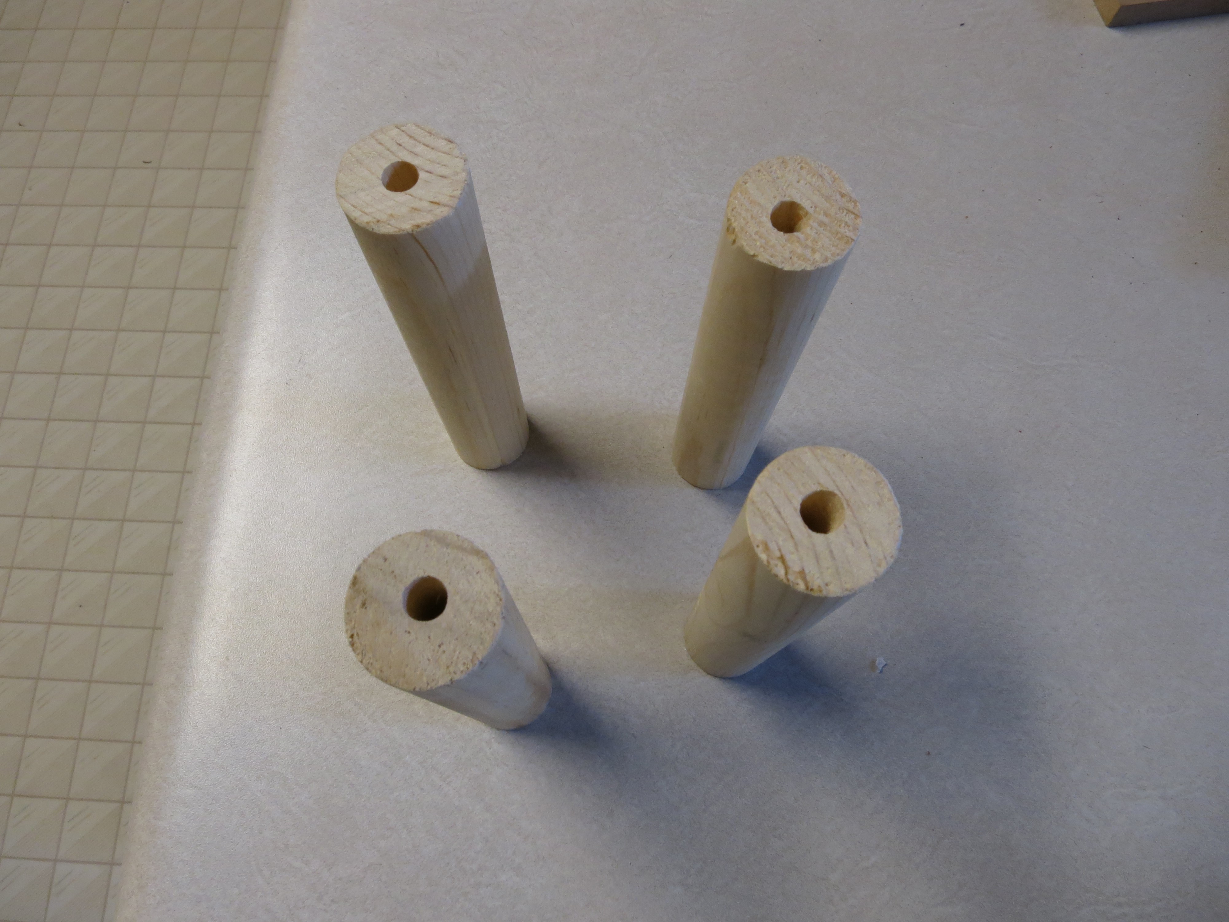
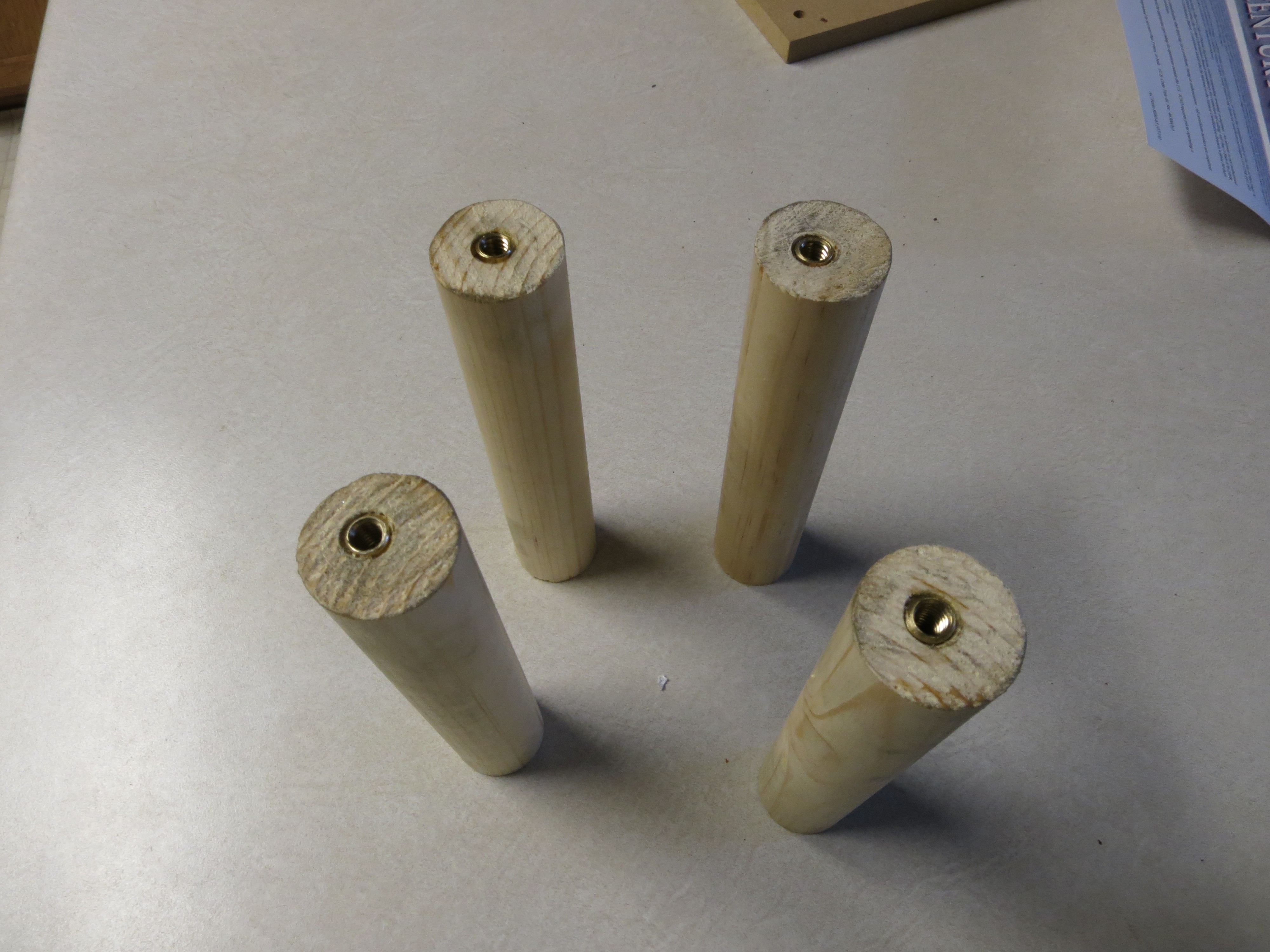
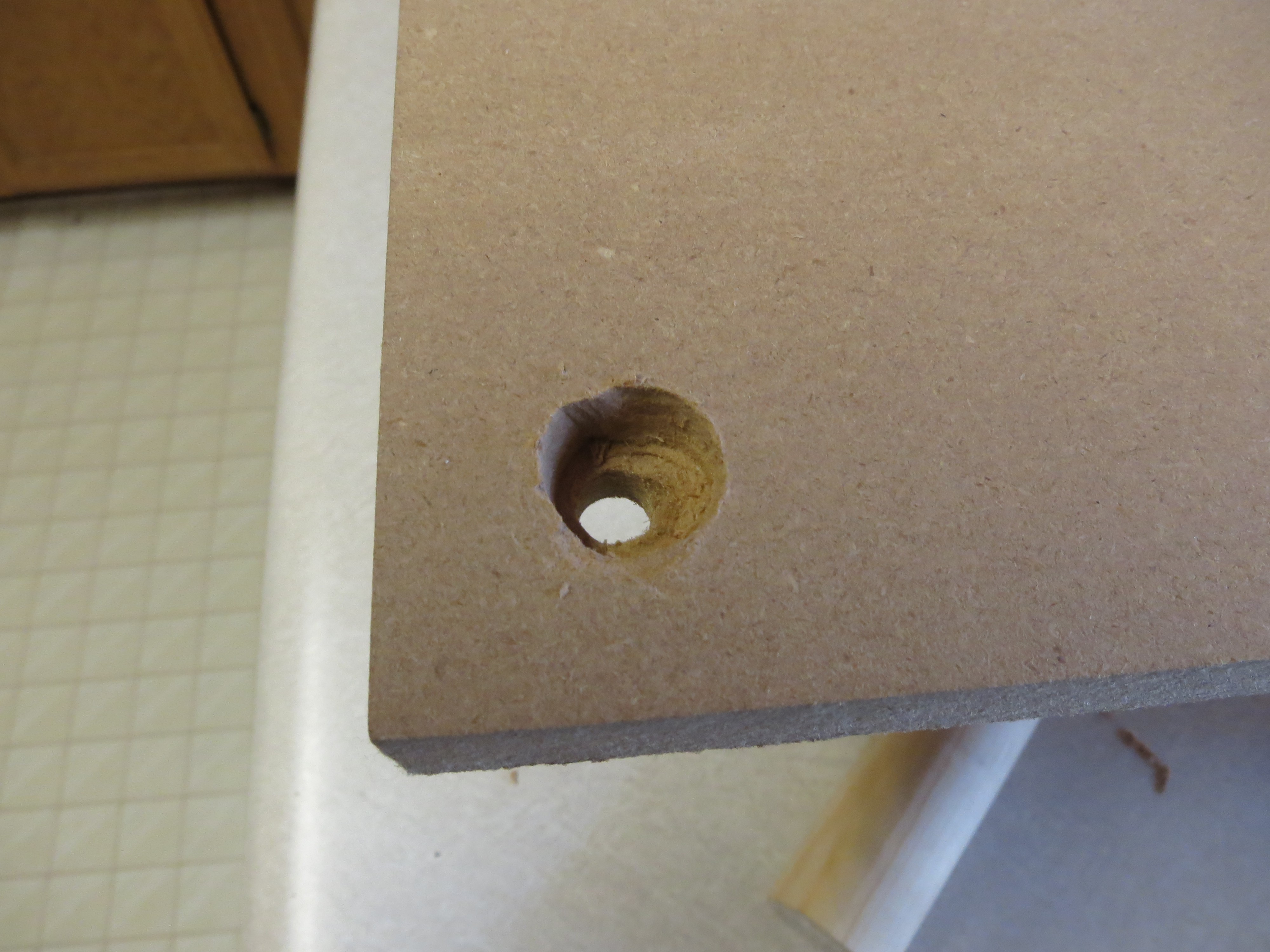

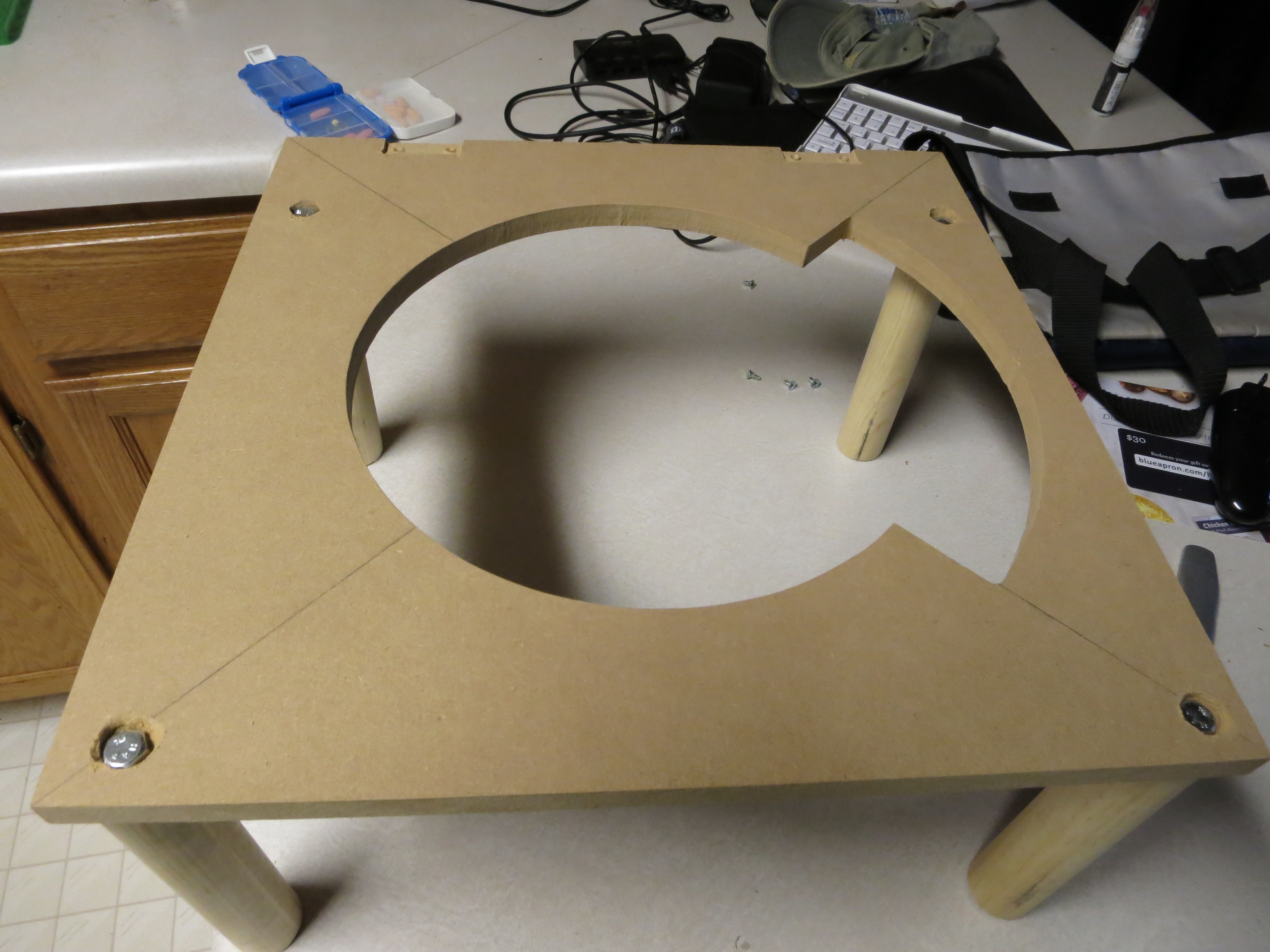
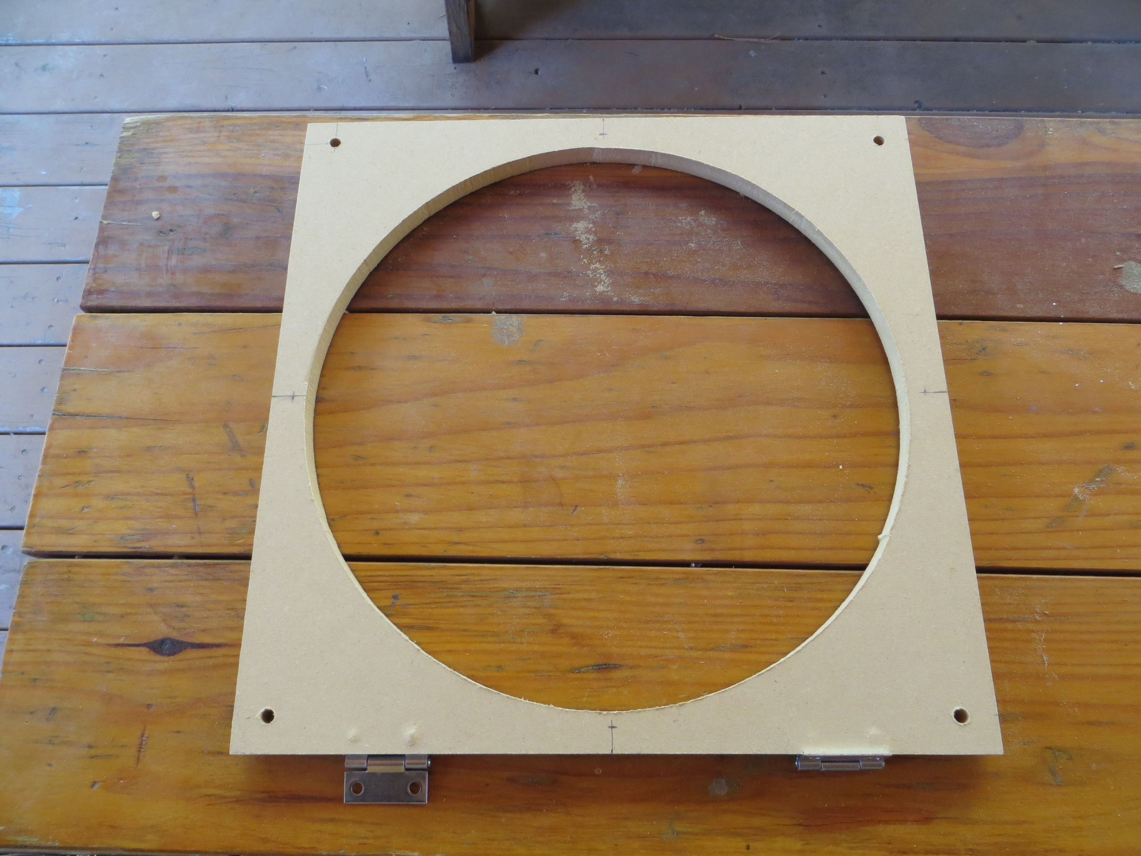

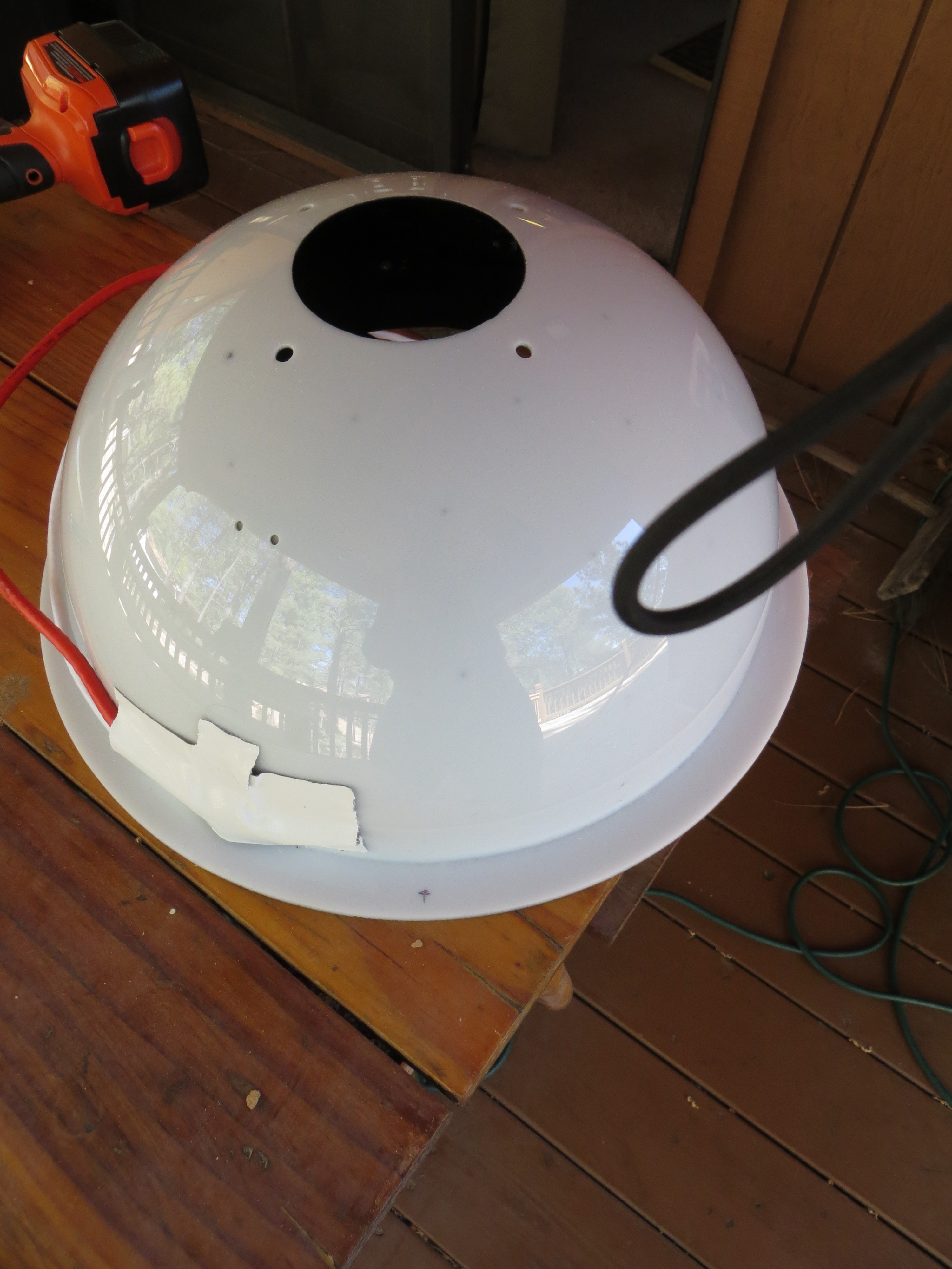

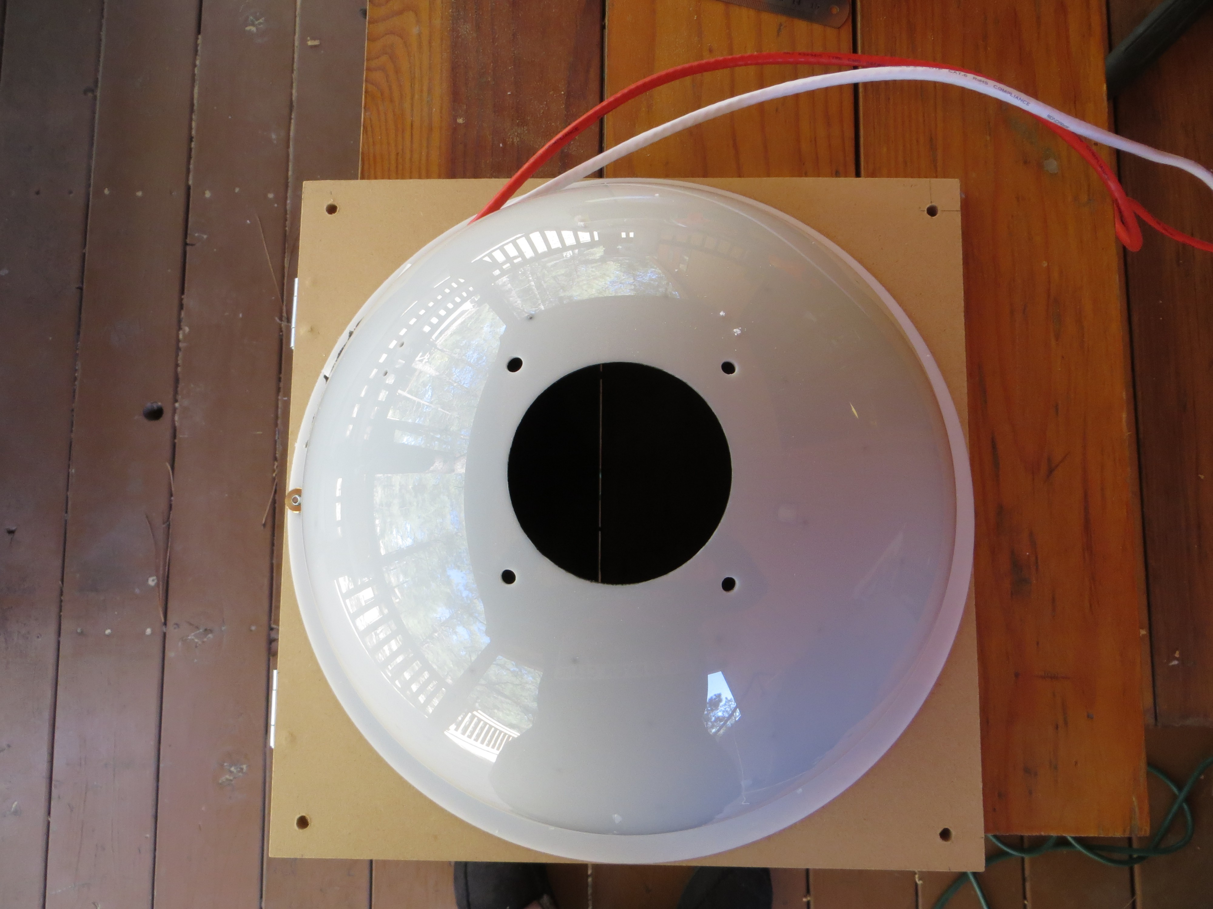
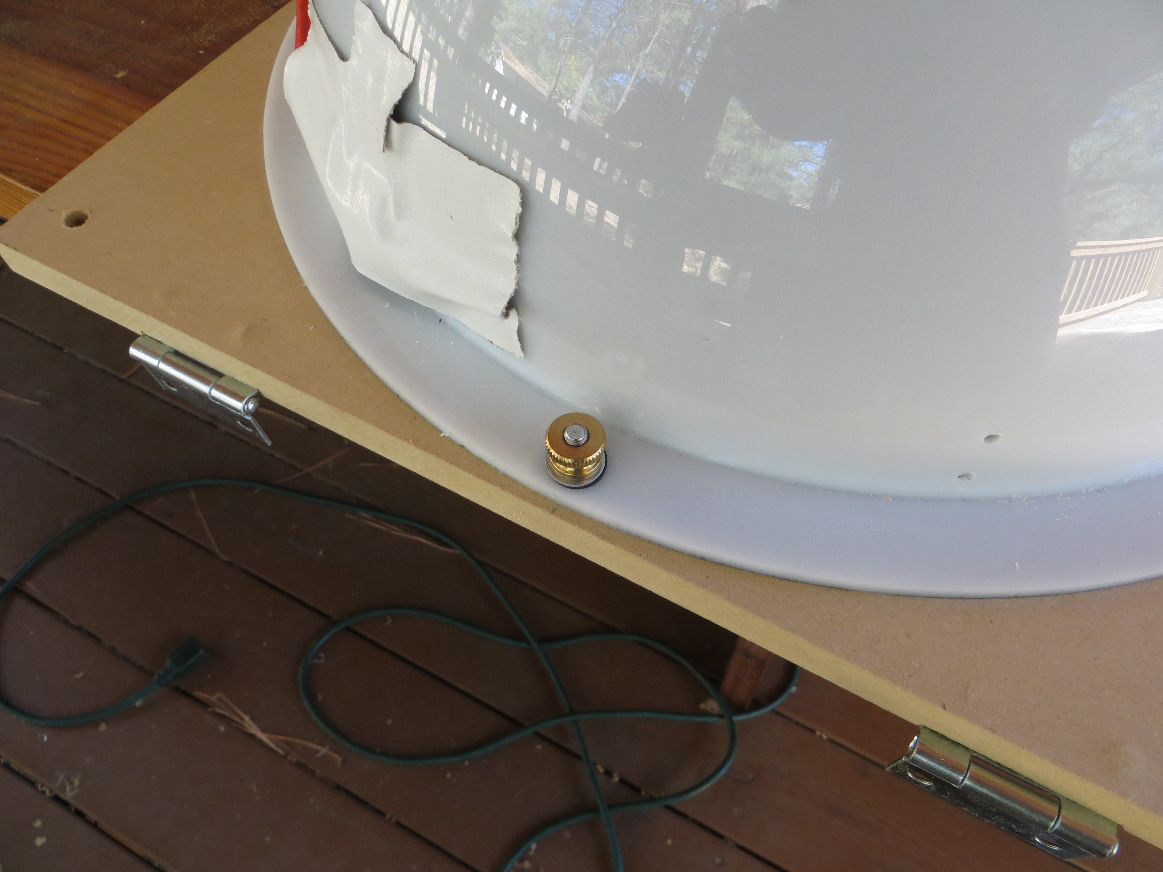
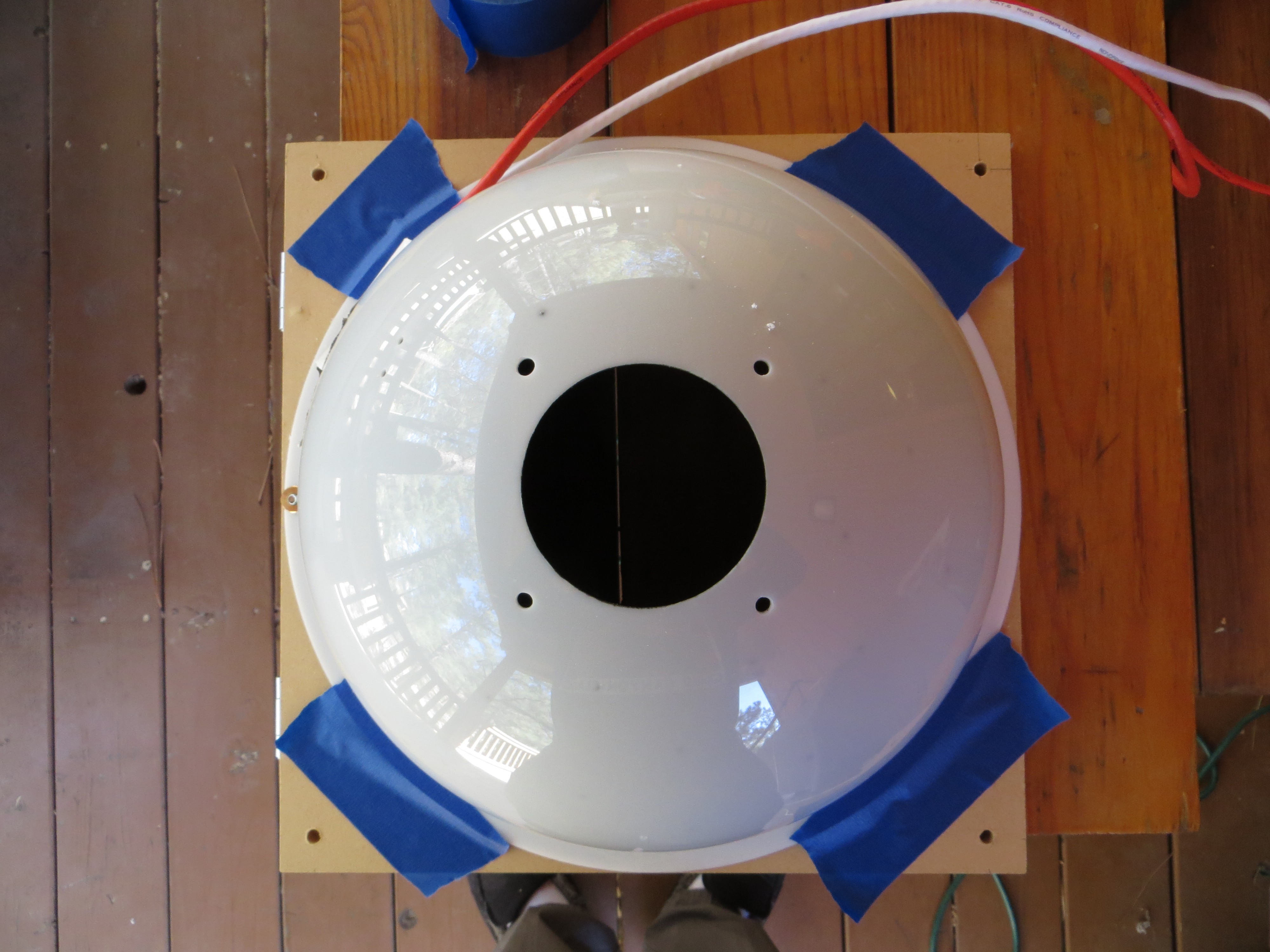
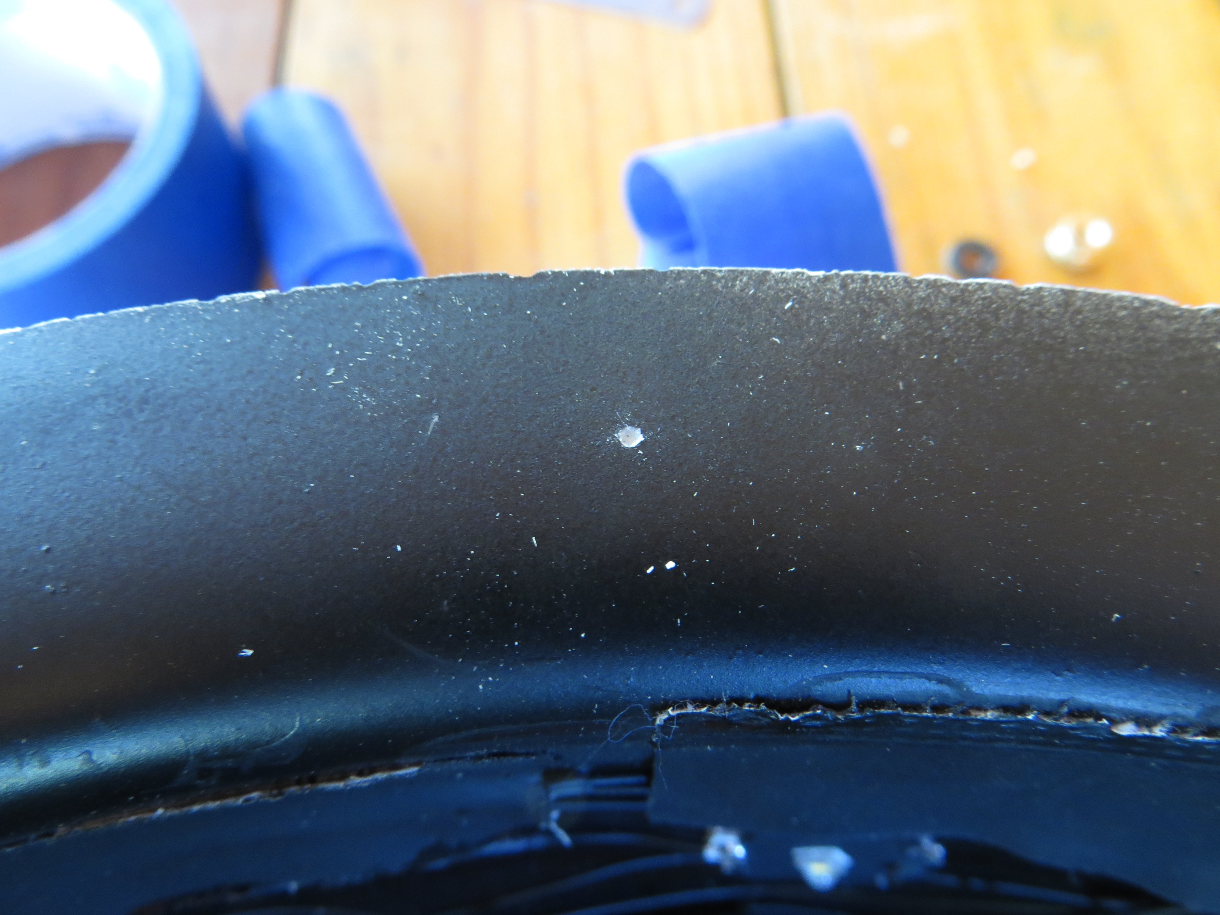
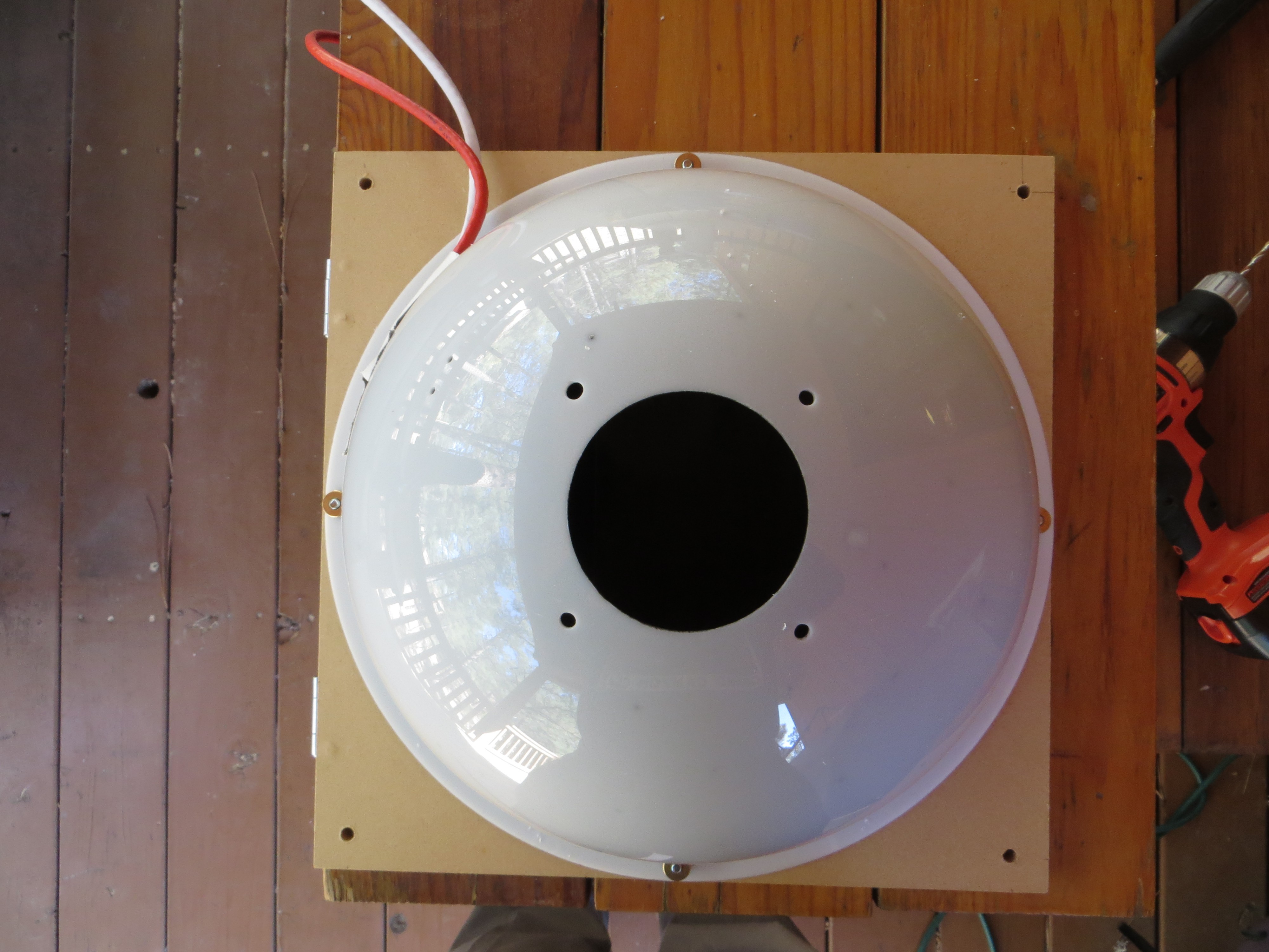
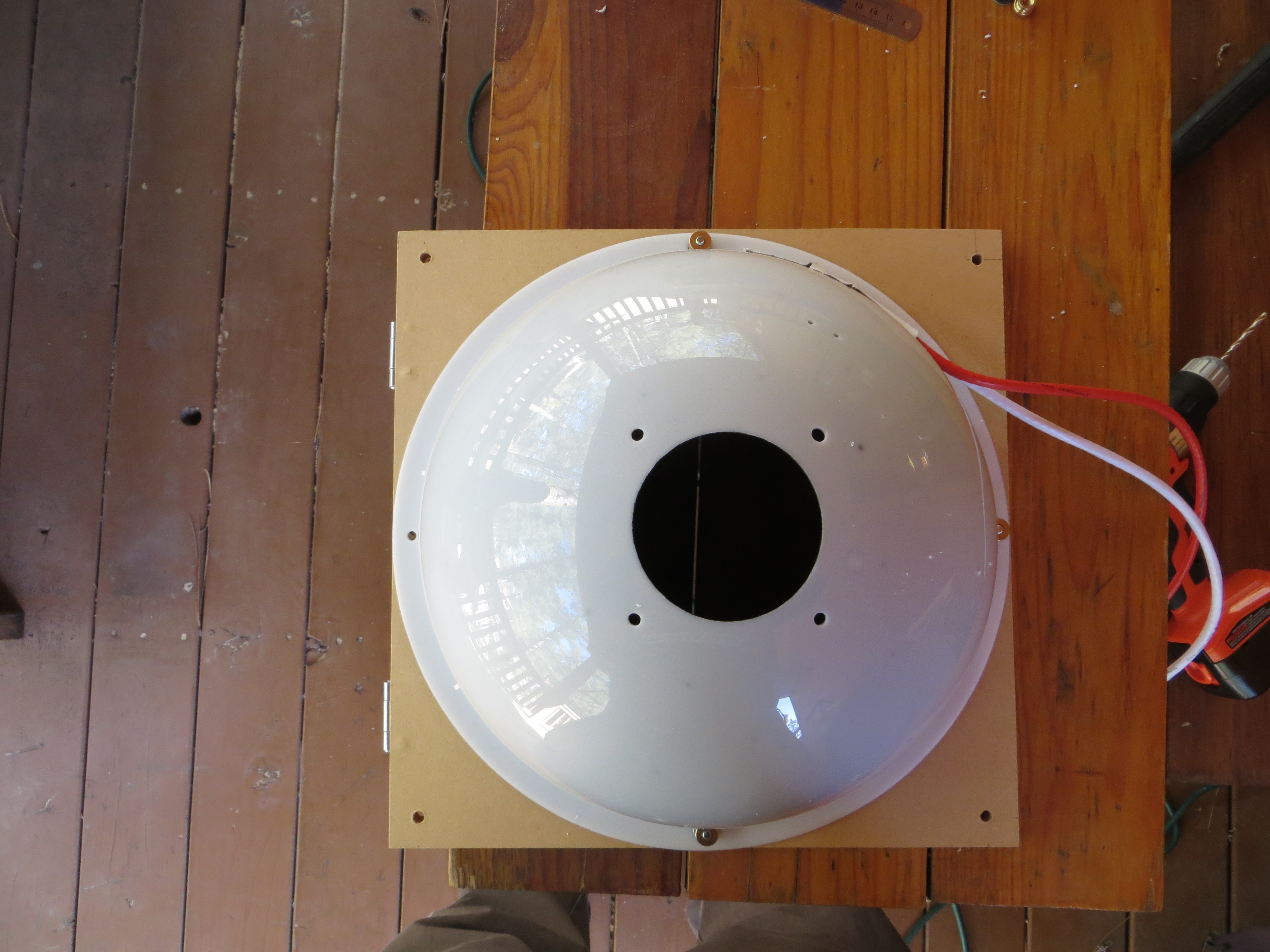
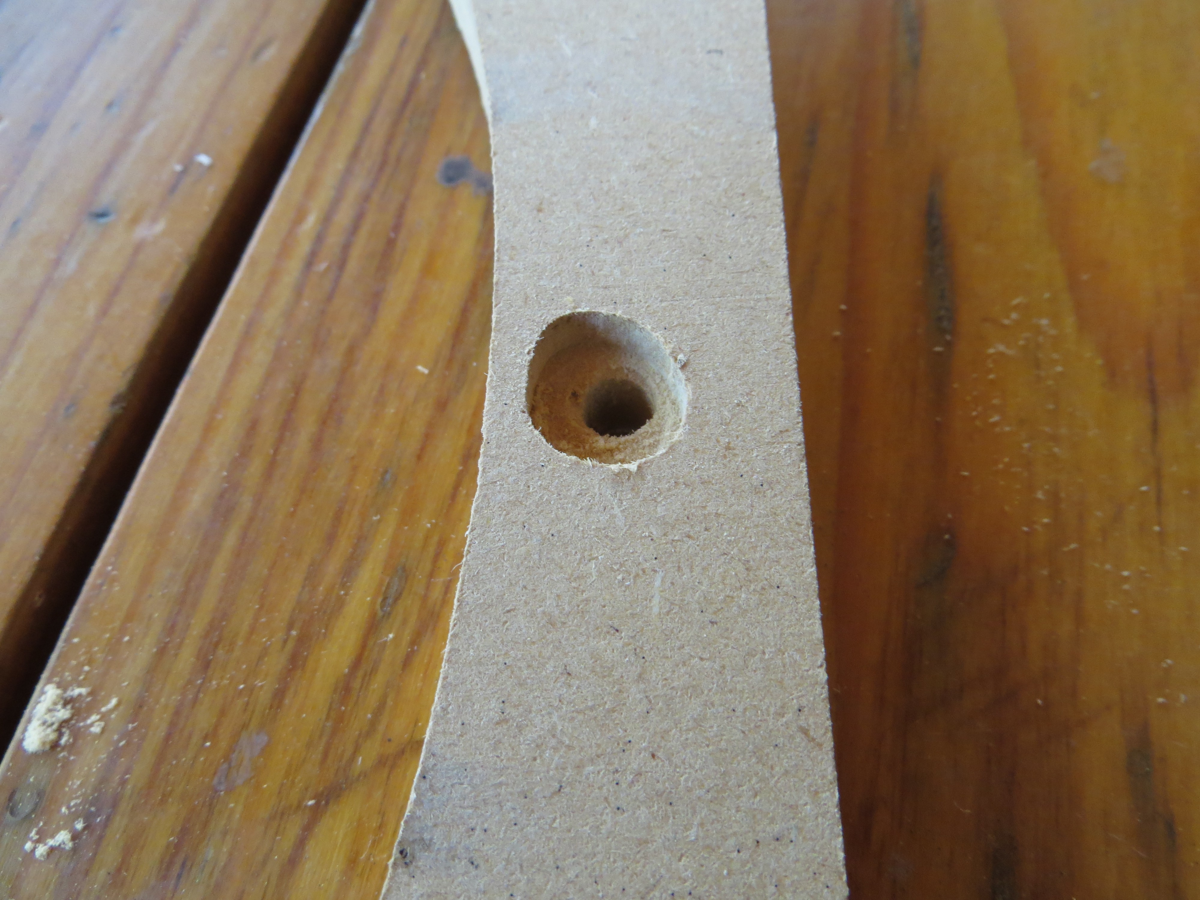
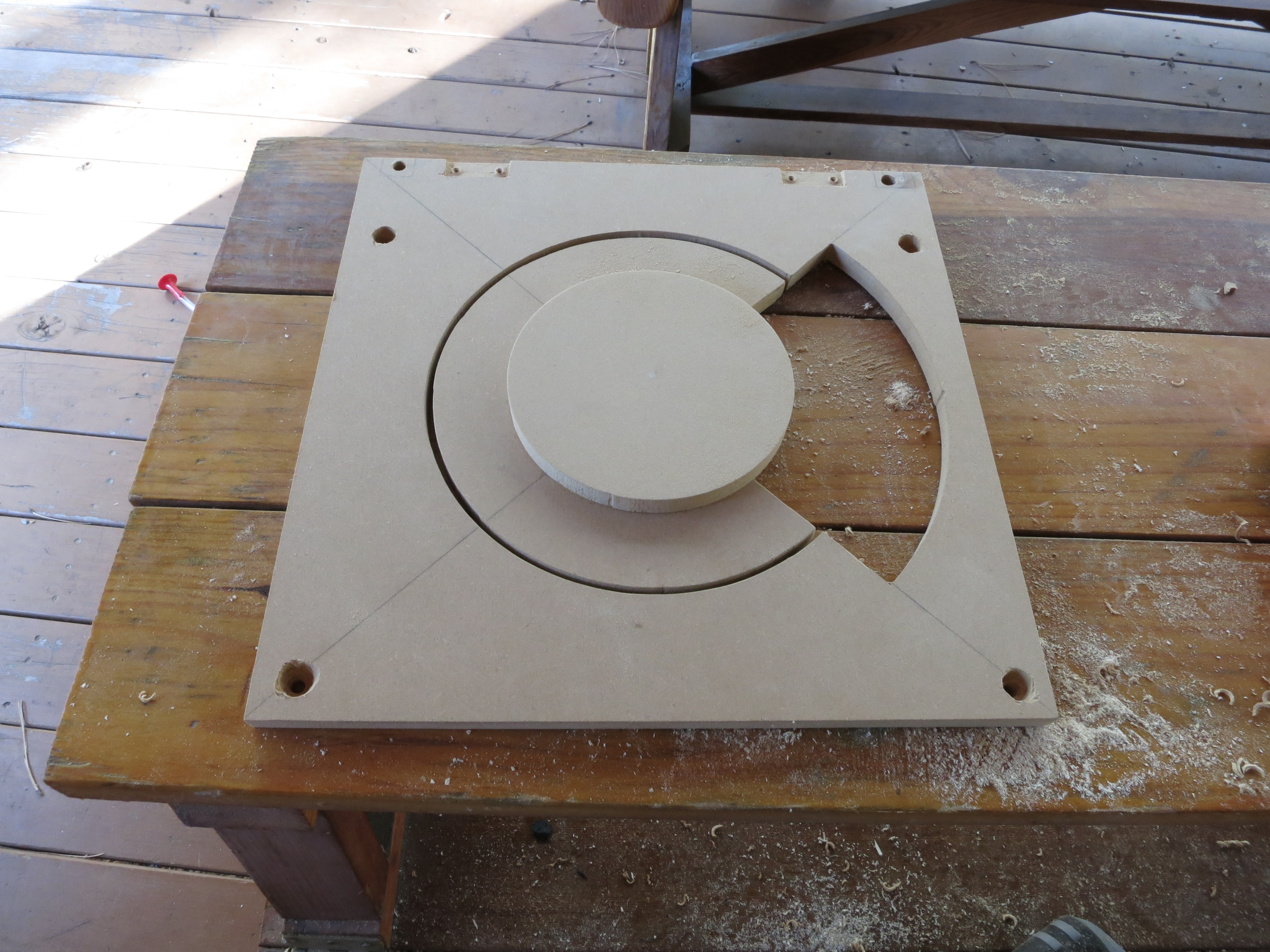

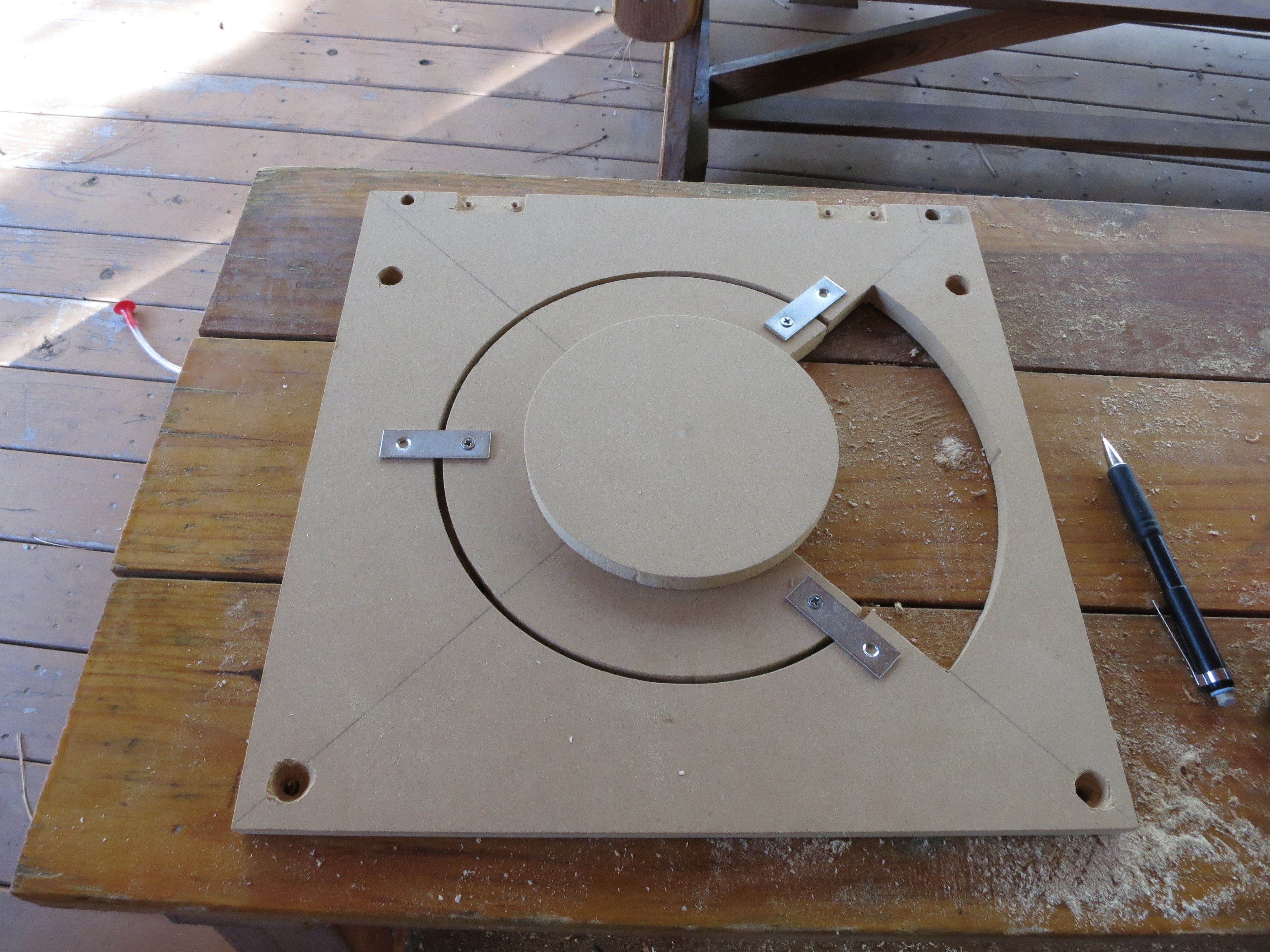
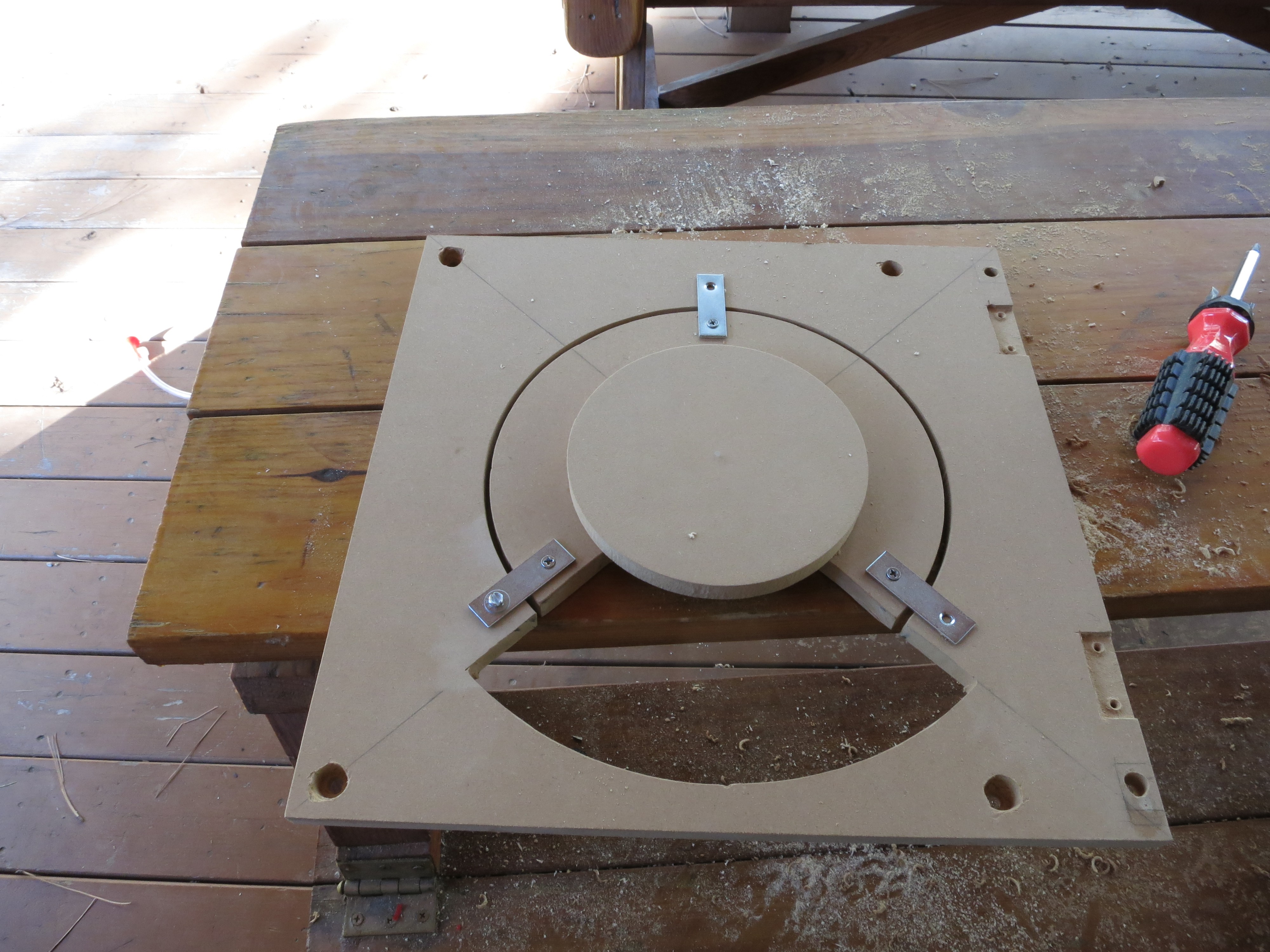
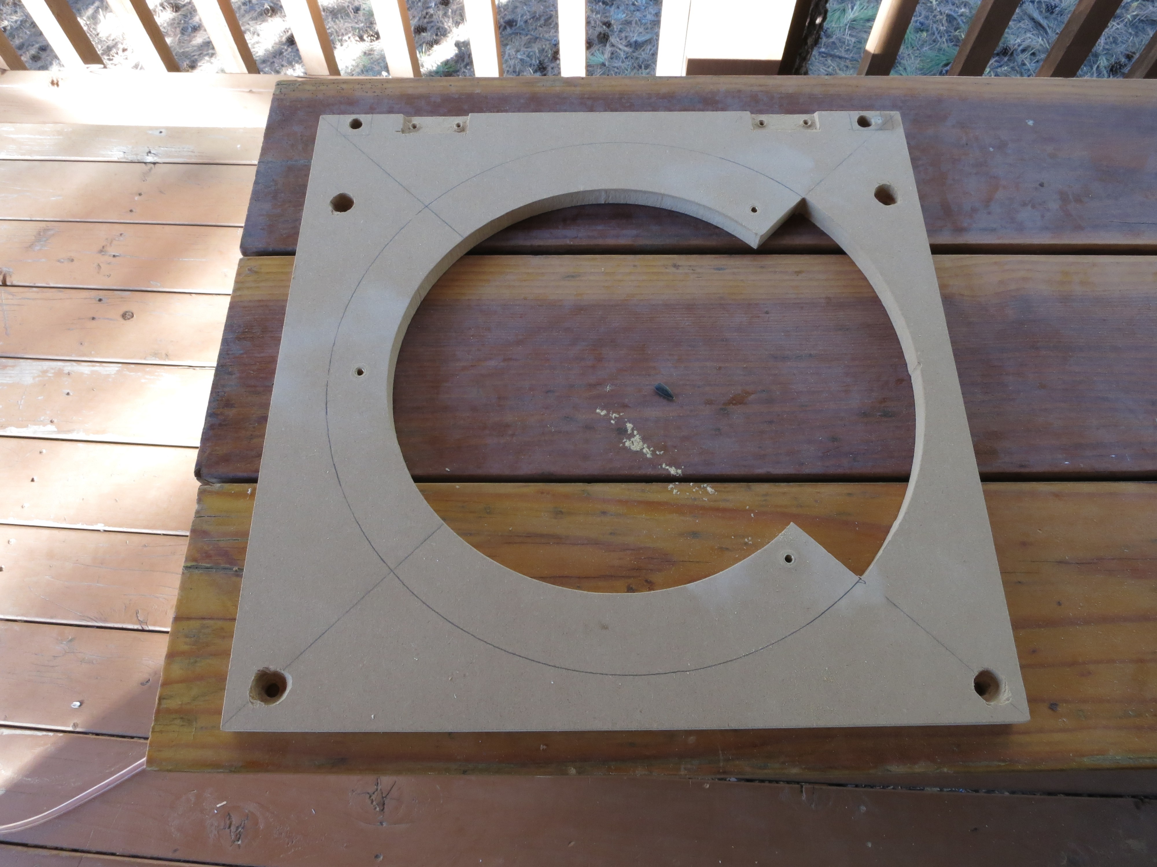
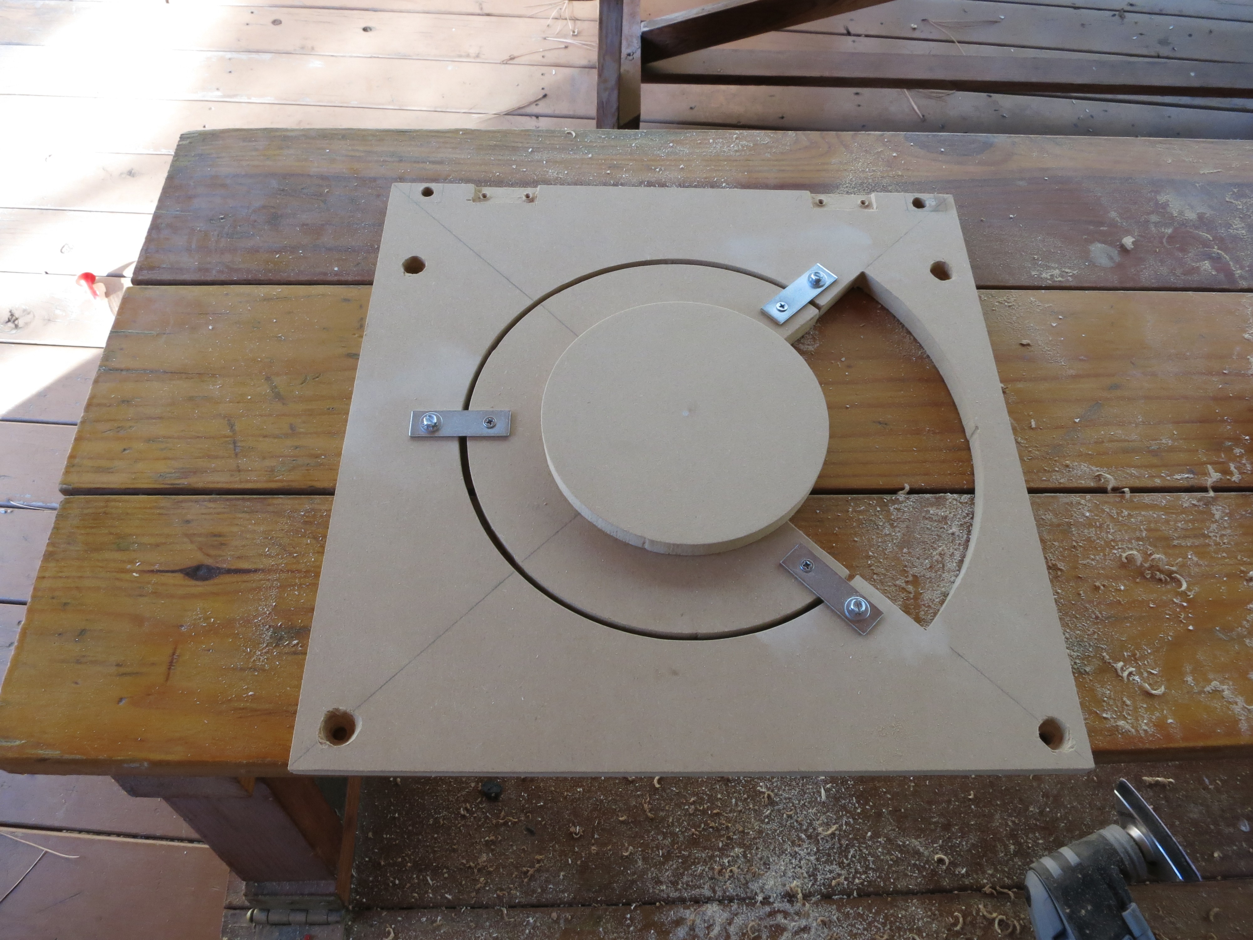
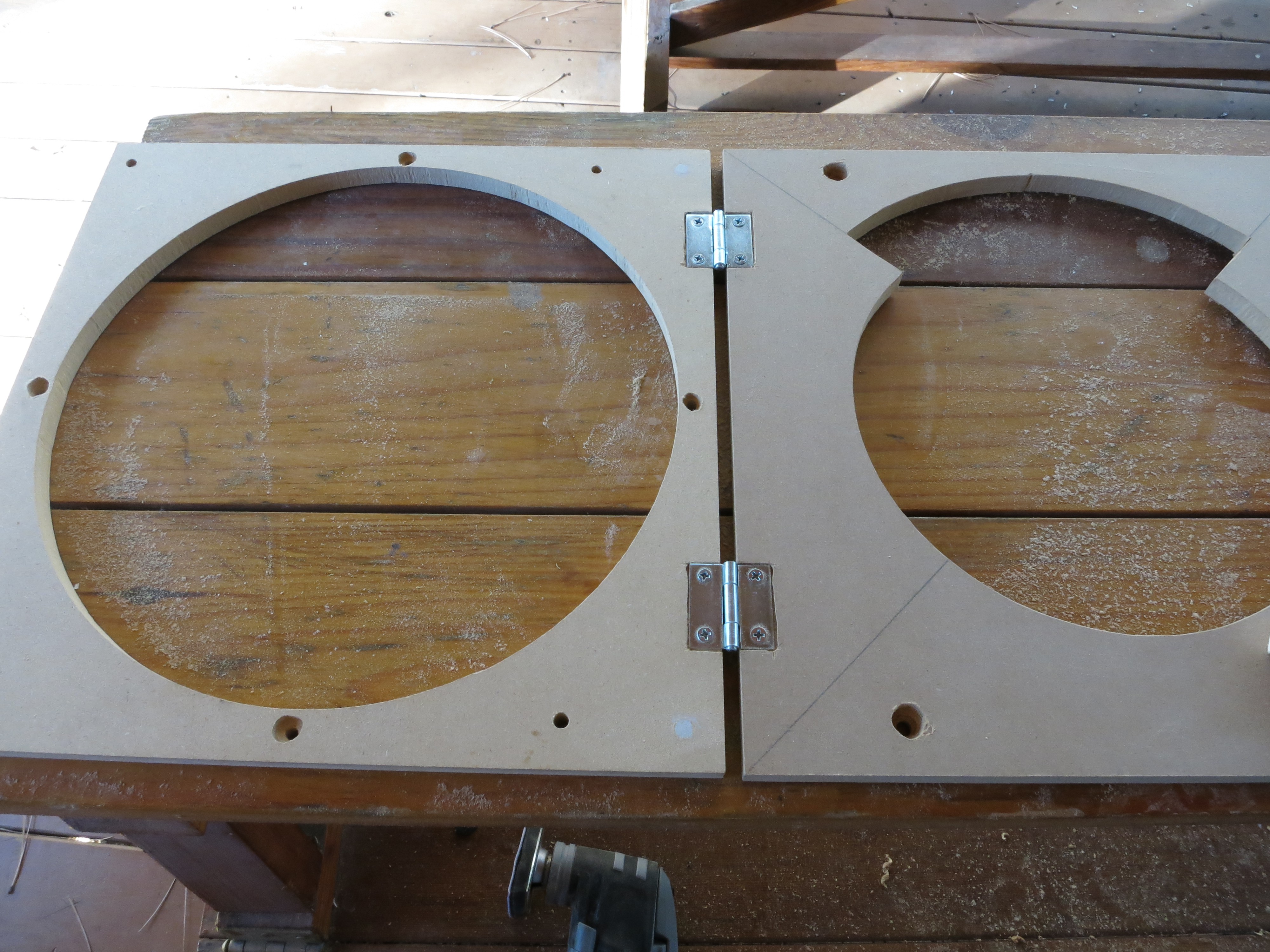
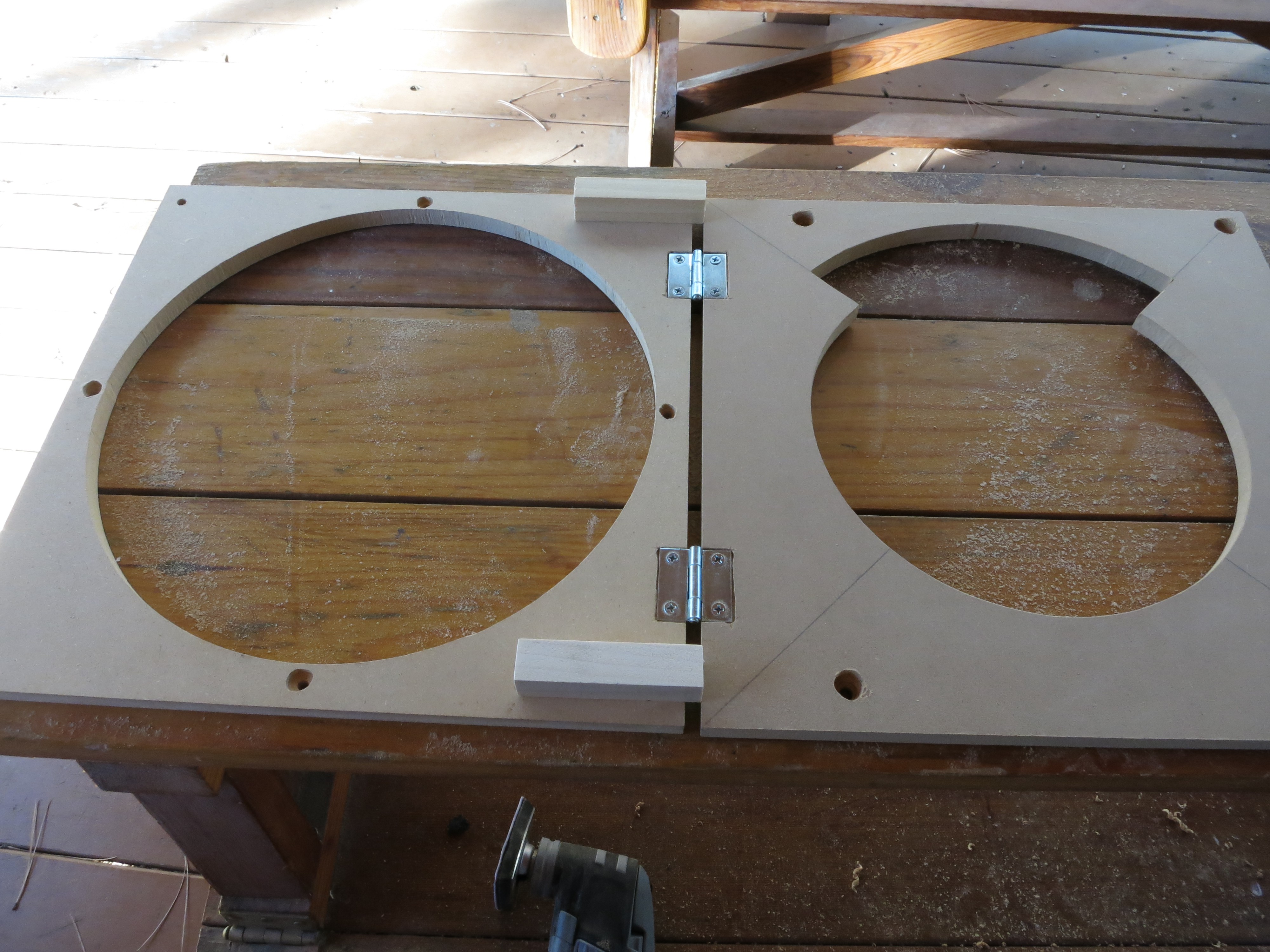
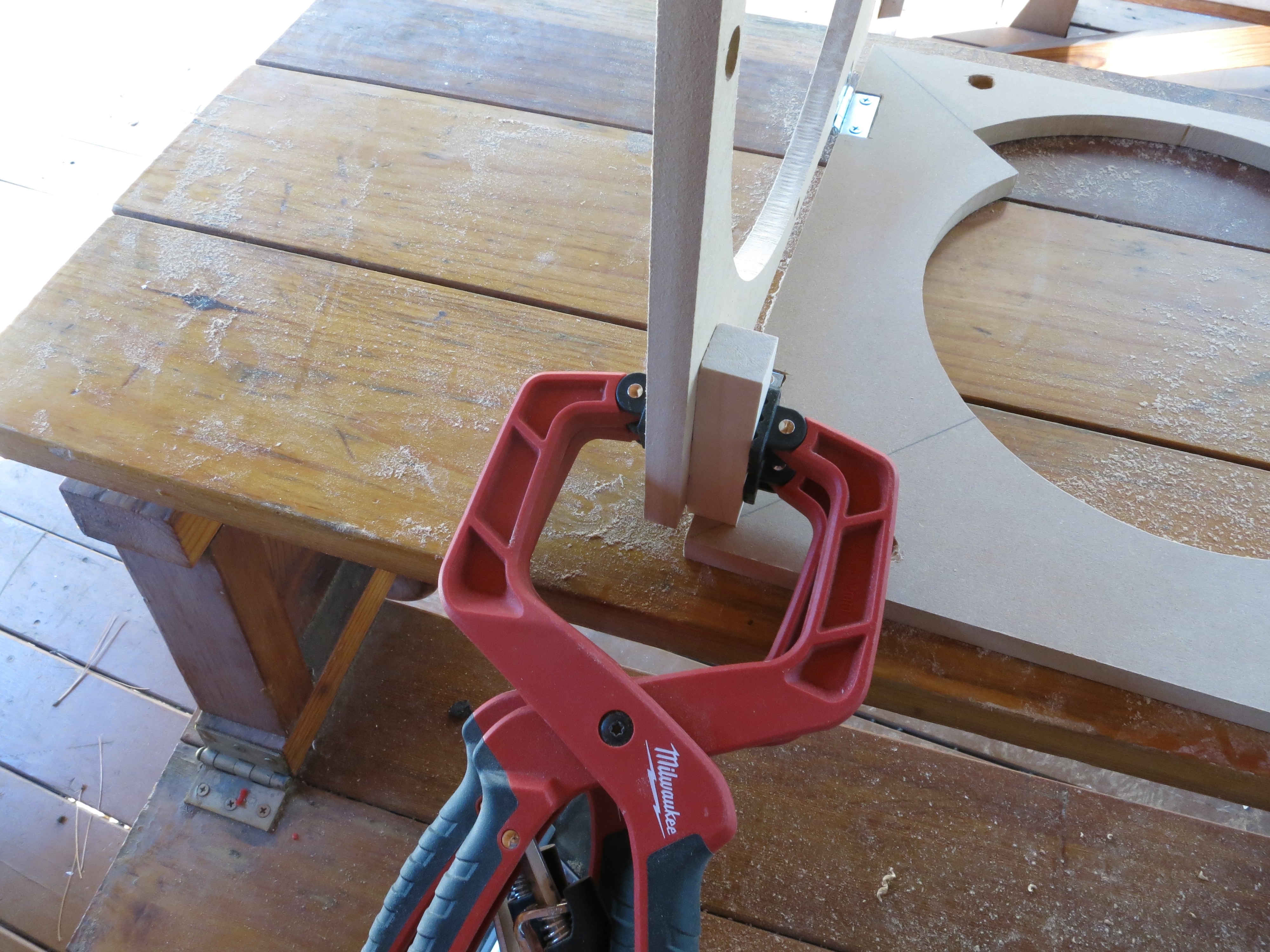
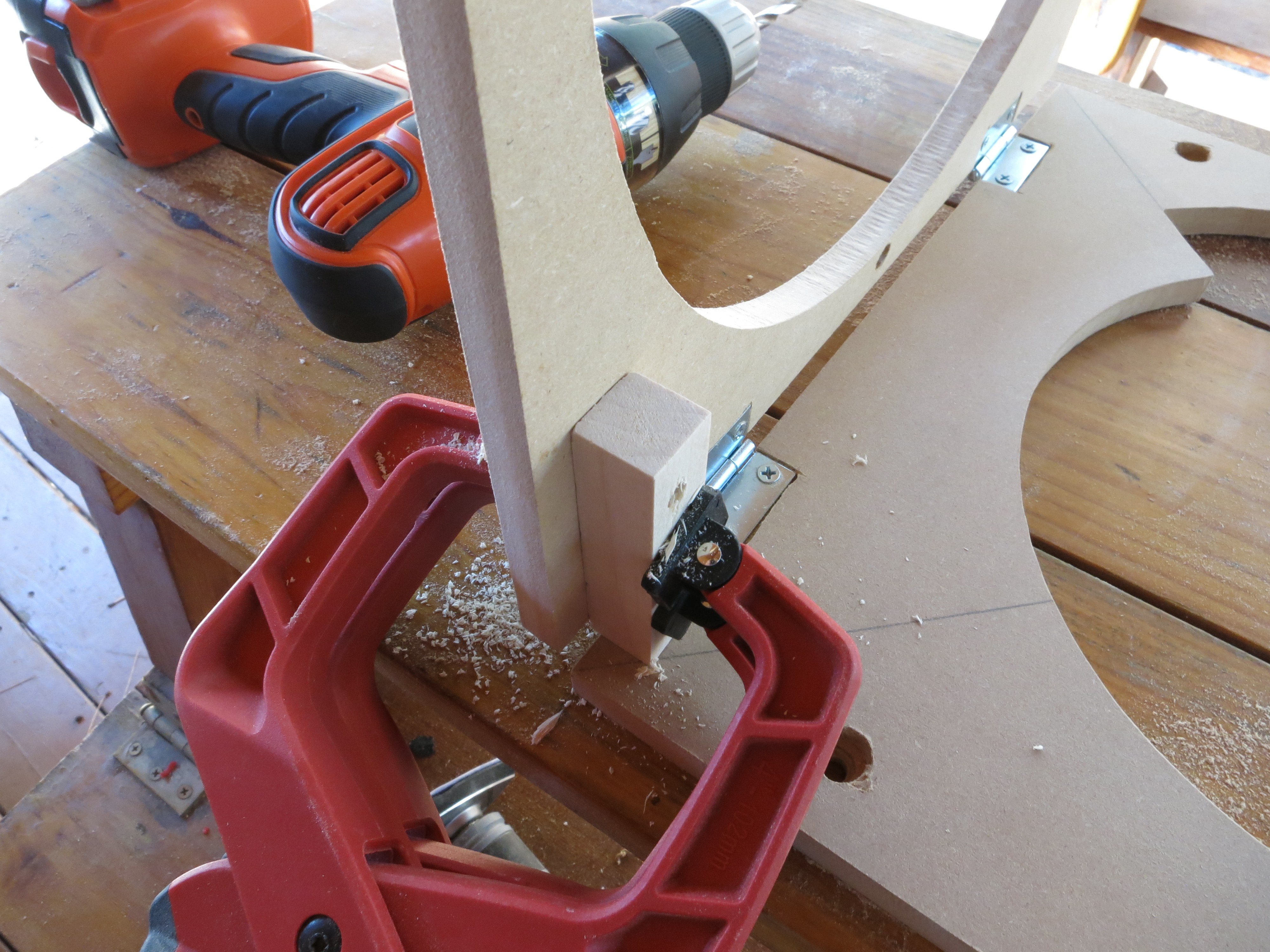

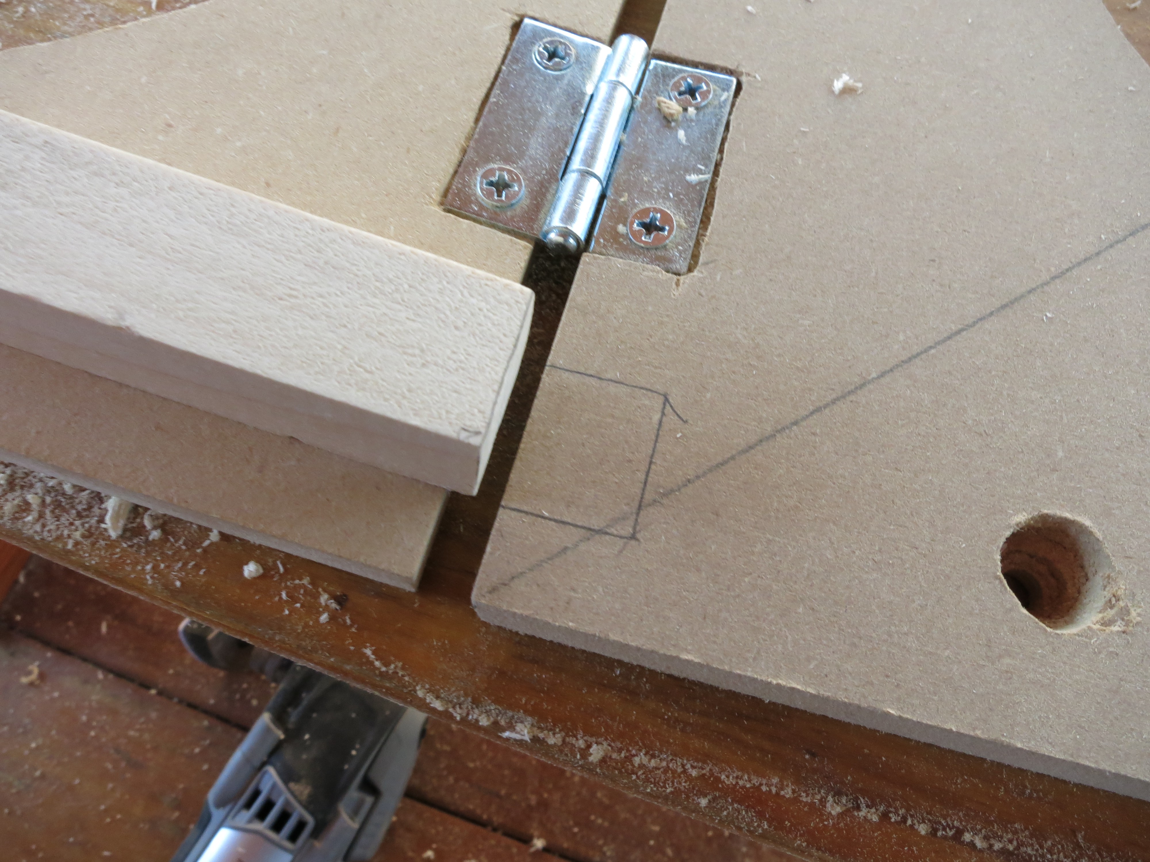
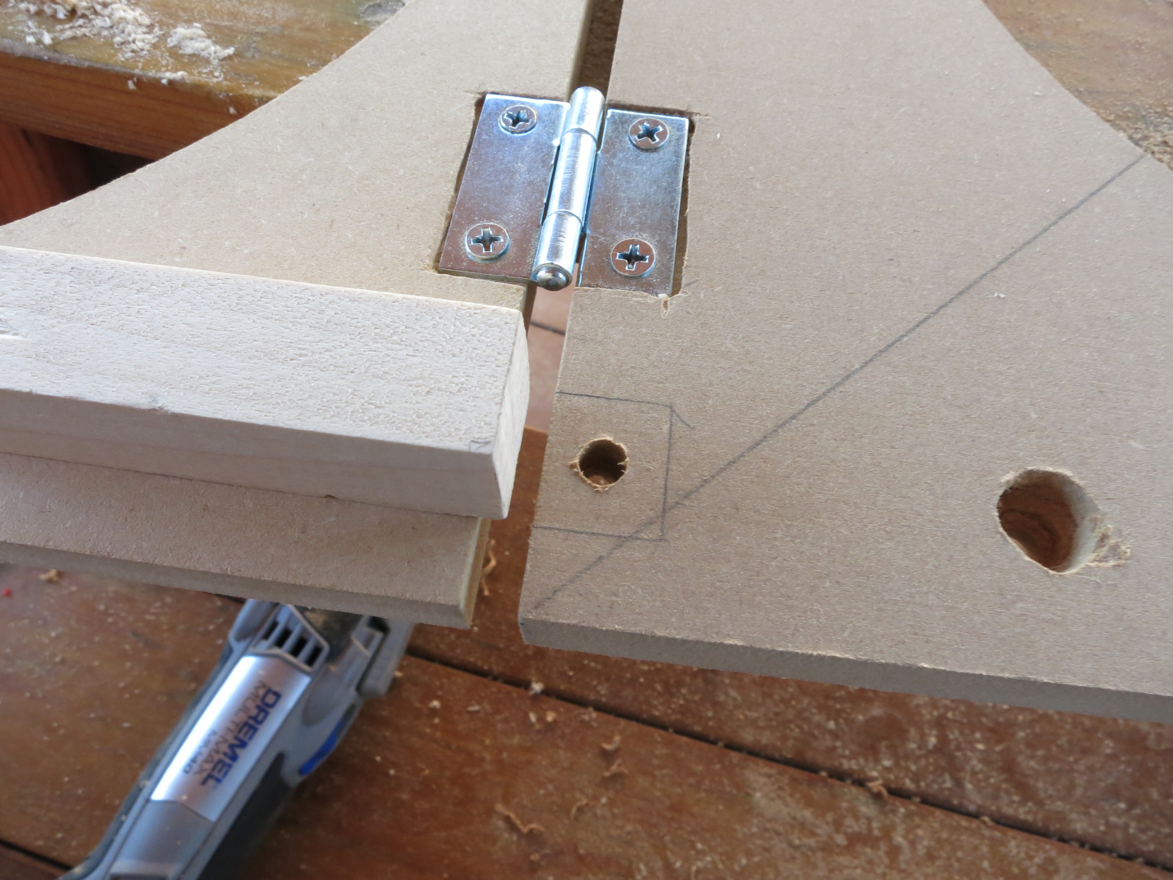
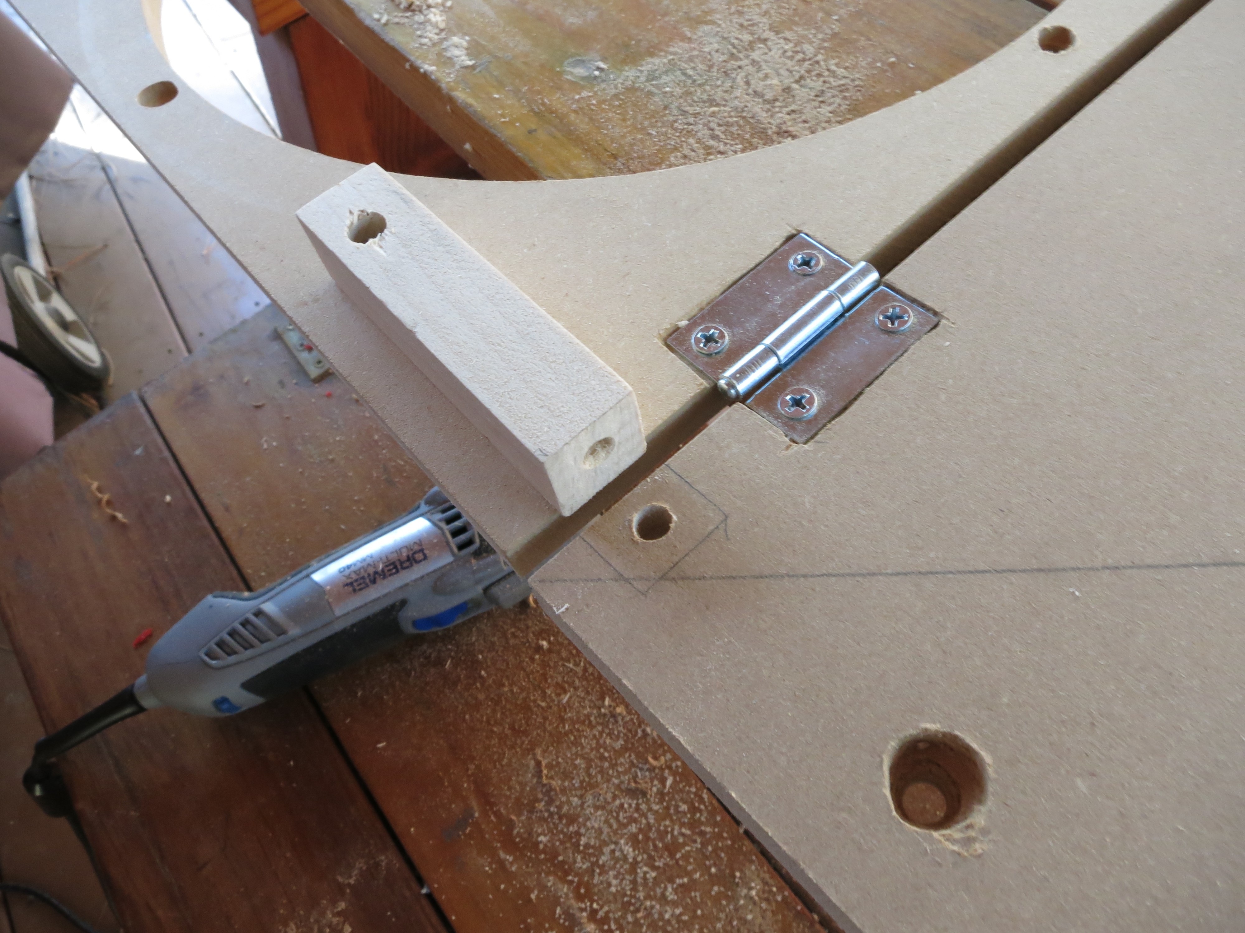

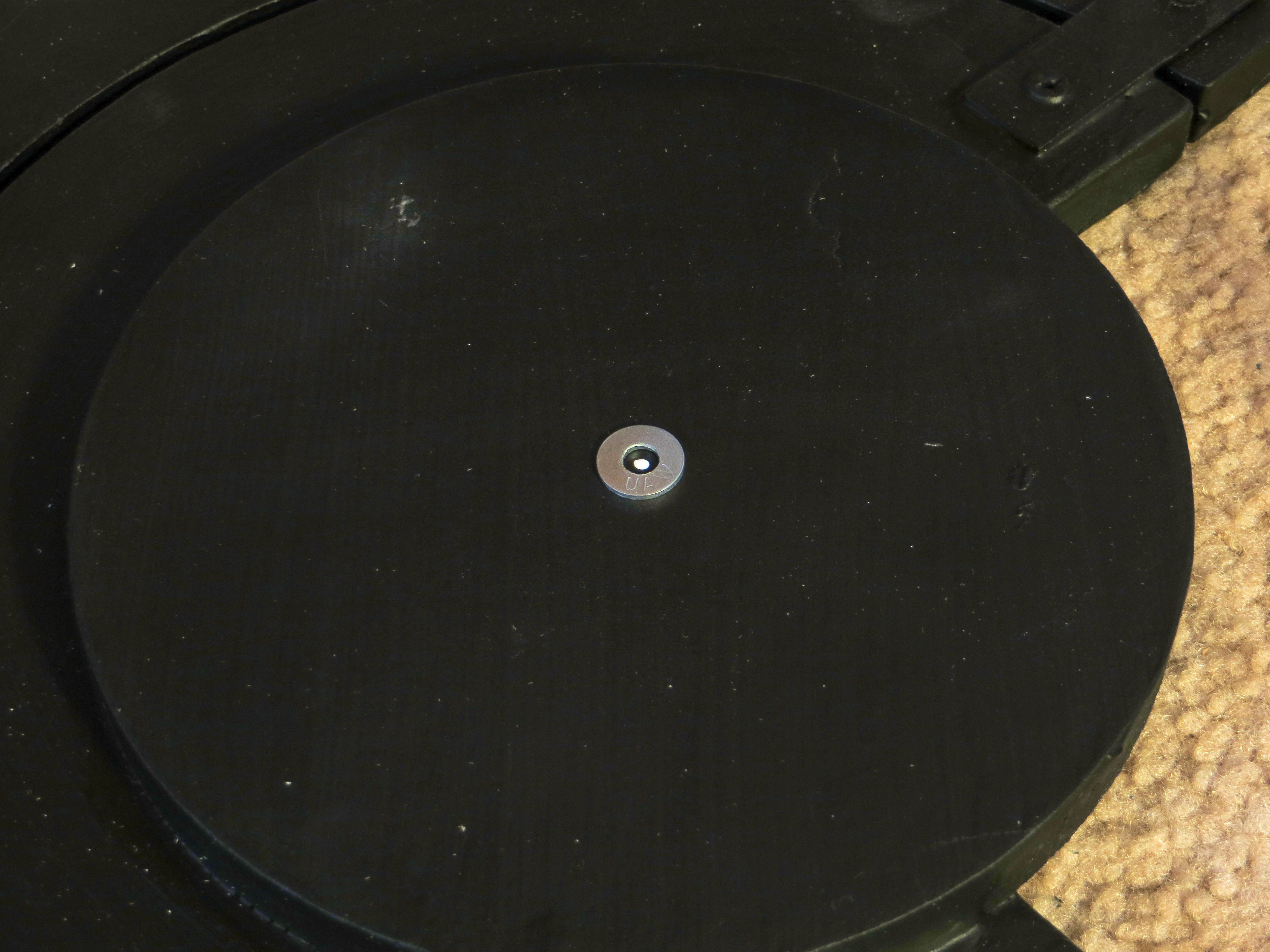
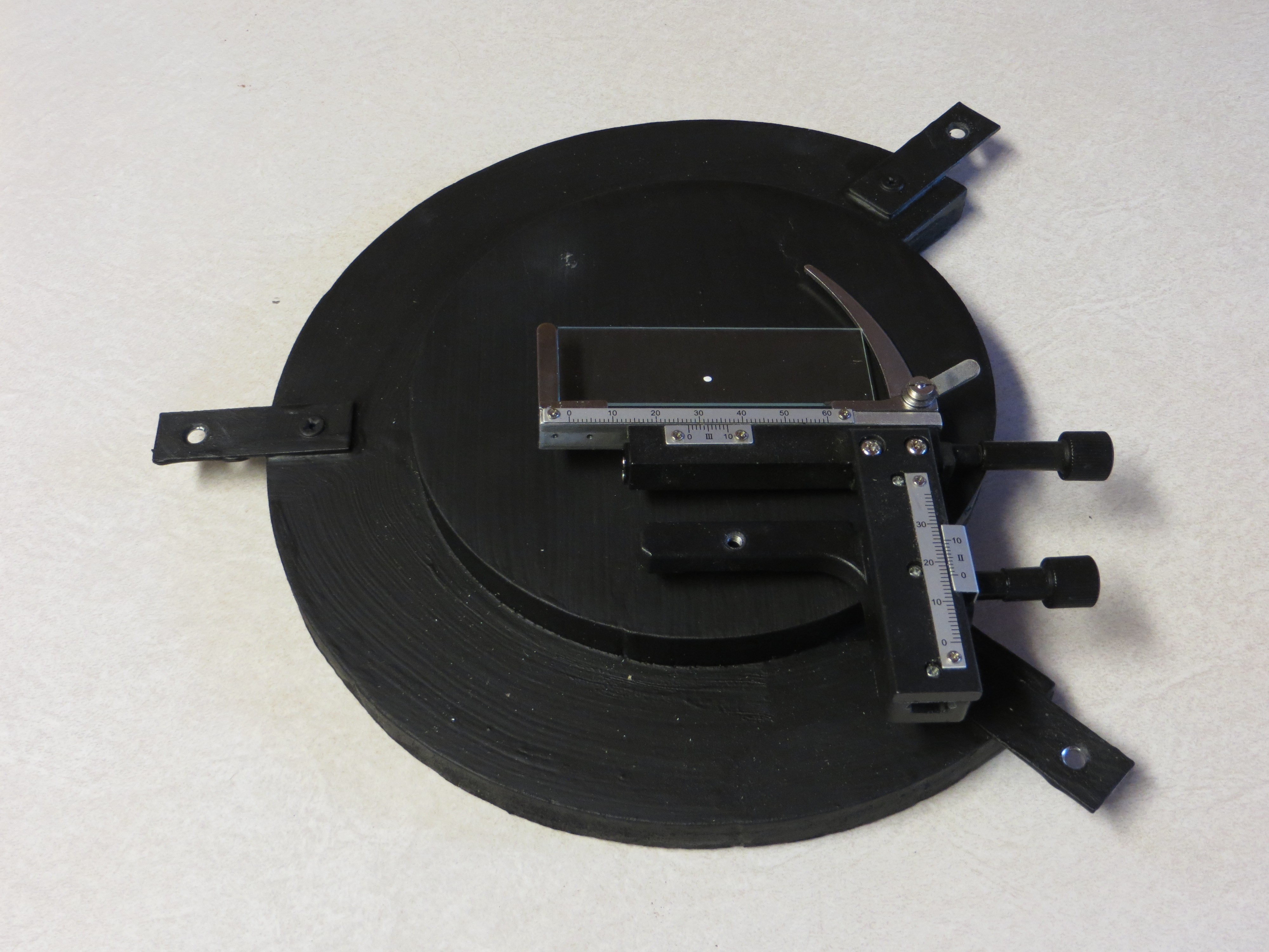
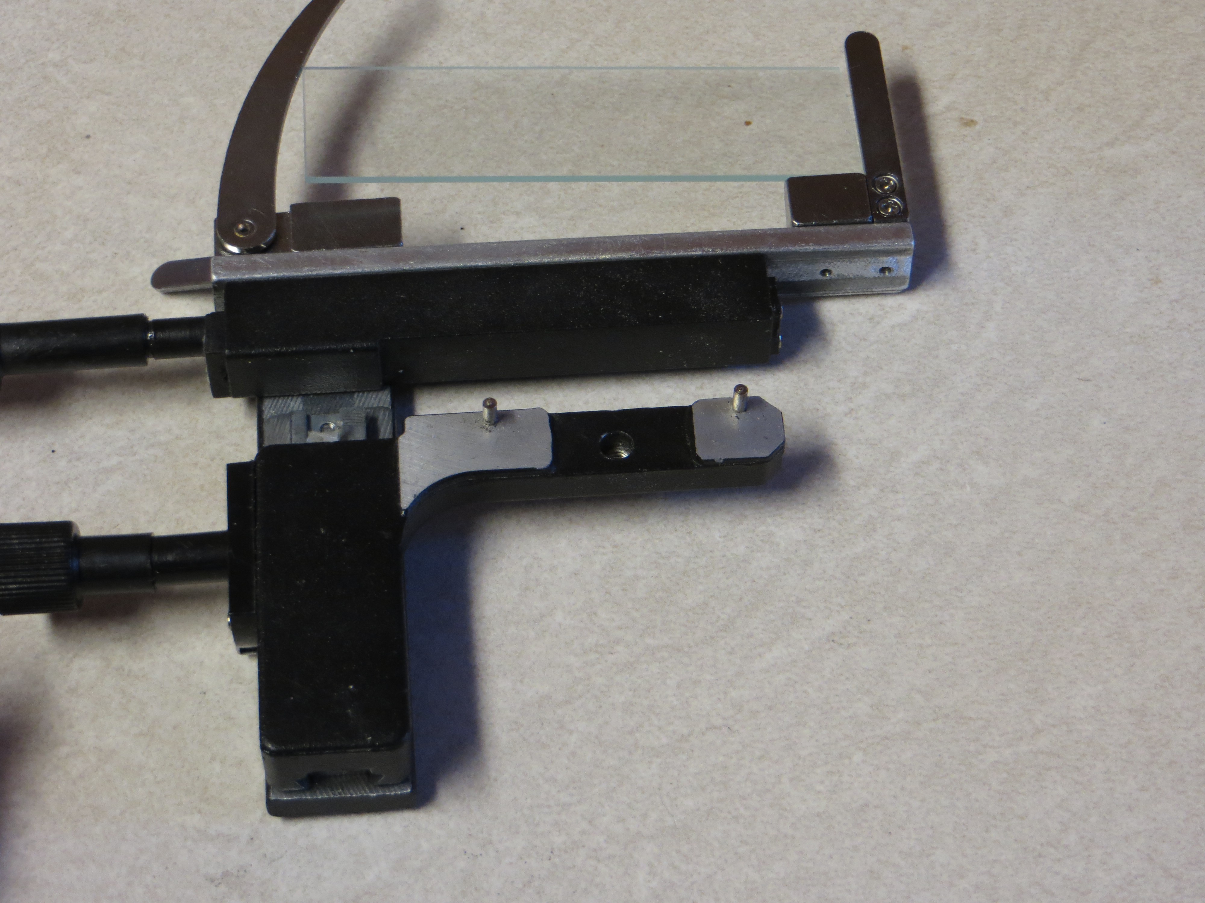
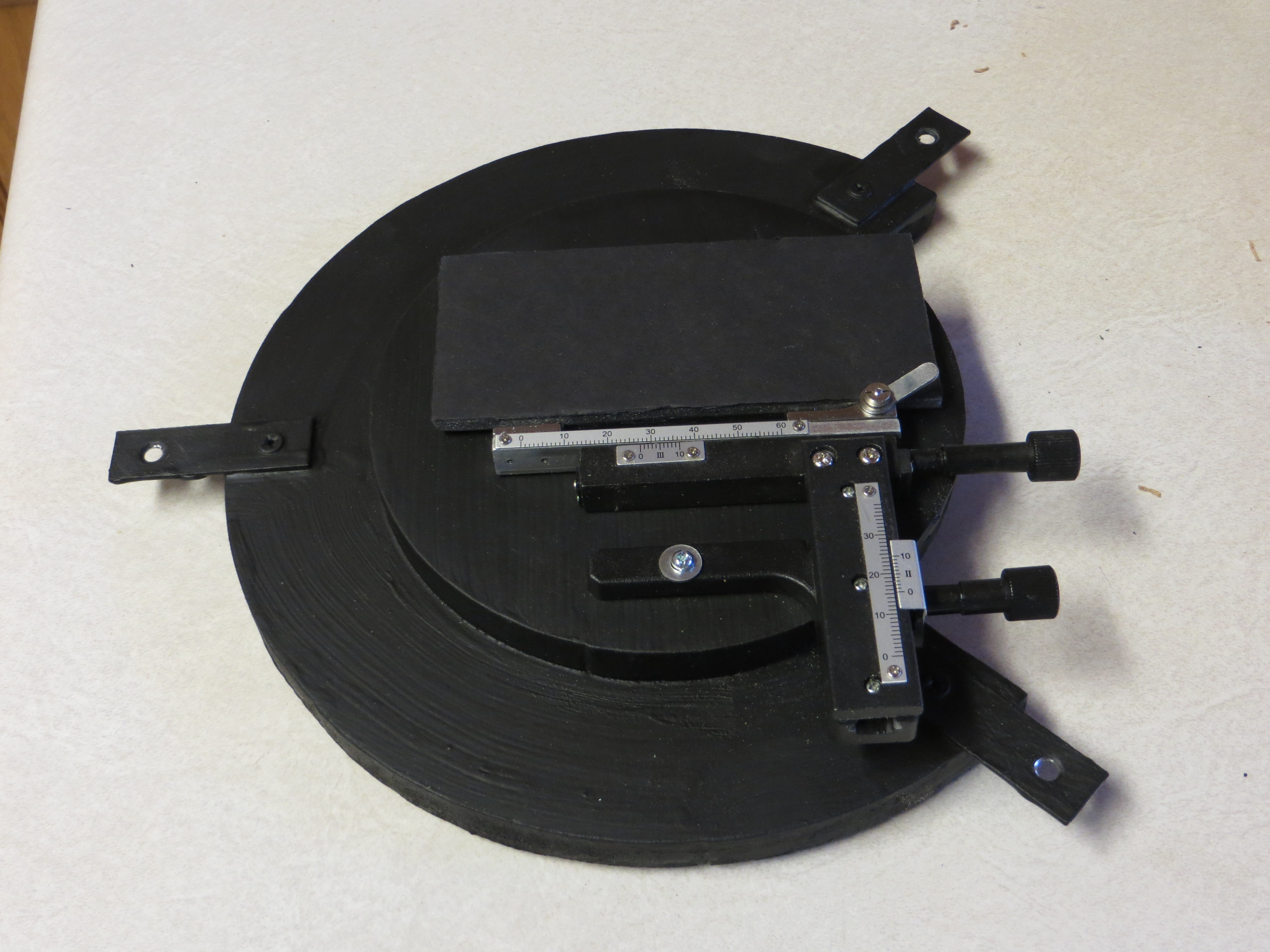
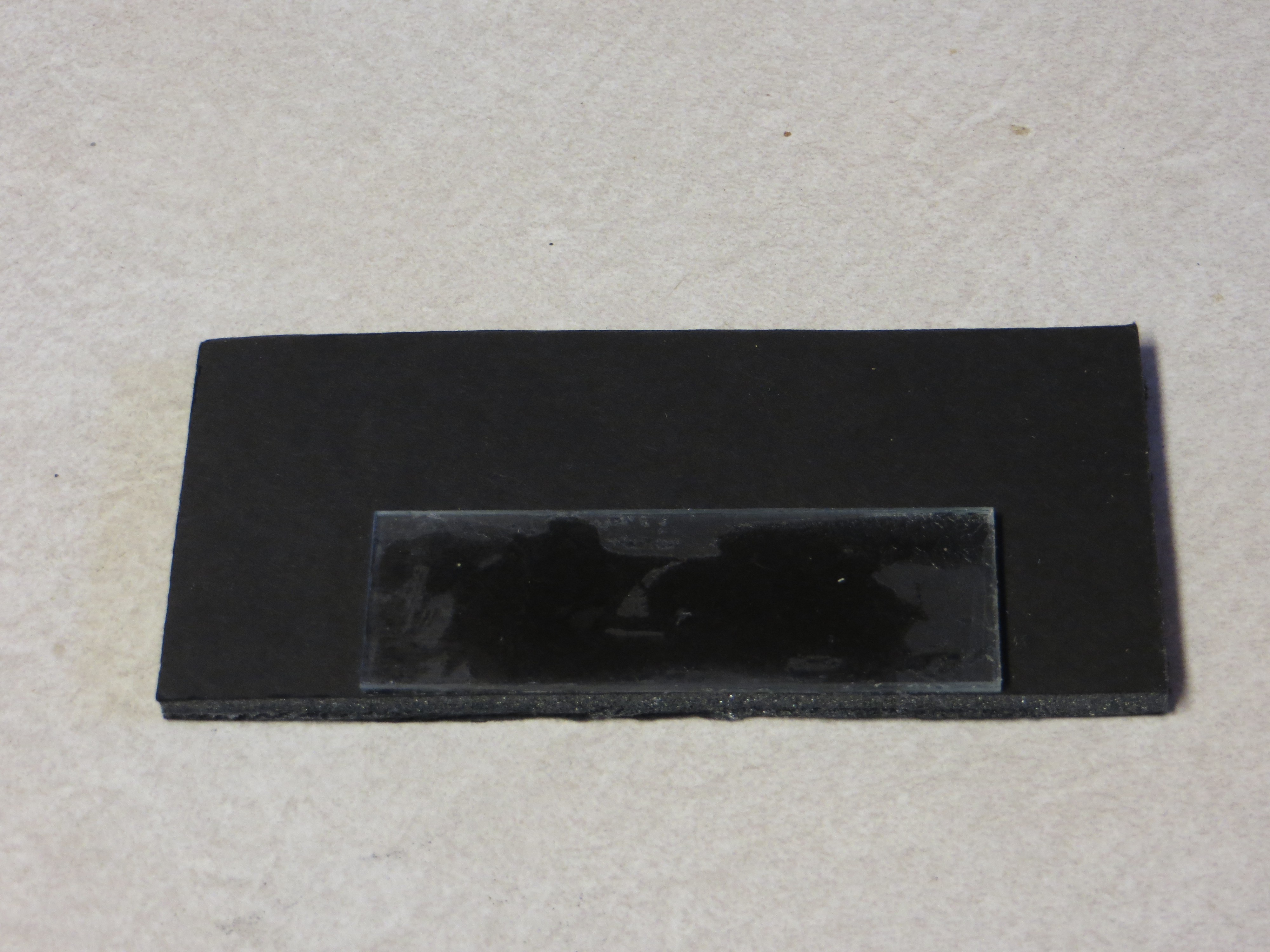
Discussions
Become a Hackaday.io Member
Create an account to leave a comment. Already have an account? Log In.