-
Dinero
07/30/2016 at 18:32 • 0 commentsThanks to the folks at Hackaday for their very complimentary blog post on my system - much appreciated. Reading it, two possible questions came to mind:
- Why are custom systems so outrageously expensive (tens of thousands of dollars)?
- Given that my system is so simple, why does it even cost $600 to build?
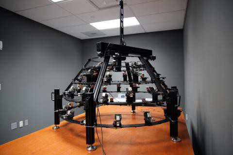
The answer to the first question is easy. These systems are typically built to the customer's specification, which often requires a design unique to that customer. The parts are often not off-the-shelf, but have to be custom fabricated. A high-quality DSLR and lens is often included, which can easily add > $5K to the cost. The design needs to be rugged, the software bullet-proof, and the whole system has to be warrantied by the builder. The builder will typically have to travel to the customer's location to install the system, and train people on its use. Plus there's the overhead associated with the organization that's building the system. It all adds up. Here's one example of a very nice custom system at the Yale Institute For The Preservation of Cultural Heritage, built by Cultural Heritage Imaging:
![Custom RTI system at the Yale Institute for the Preservation of Cultural Heritage]()
That's a really sweet system - if I win tonight's Powerball, I just might order one like it :).
Having said all that, one of my systems is capable of producing comparable results to the one above, even if it doesn't look quite as elegant. Which leads to the next question: given that this is just a bunch of LEDs turned on and off inside a dome, what makes it cost as much as $600? Well, here's a list of the most expensive components in the system:
- Acrylic dome - Cost of this depends on size. The dome for the 12" system whose build I'm documenting here cost about $86; an 18" dome for a previous system cost about $135; and so on for larger sizes.
- LEDs - This is the number one cost. I use 3W/1A Cree LEDs on a star heatsink; smaller/less powerful LEDs just won't cut it. As I mentioned in an earlier log, don't cheap out on these - buy them from a reputable source. Chinese websites advertise "Cree LEDs" for less than a buck each in quantity, but the quality of these is dubious, as I found out to my chagrin. Last time I bought these, I paid about $3.30 each in quantity; just checked the price at LEDSupply, and they're down to about $2.75 in quantity. For a 12" system, you'll need 48 (plus a few spares), so that's about $150; for an 18" system you'll need 64 plus spares for about $200.
- Enclosure - The only enclosure I found big enough to hold the Arduino and accessory parts is this one from Polycase for about $14; however shipping kills you at an extra $10. About $15 more for additional screws, nuts, washers, spacers, bringing the total up to about $39.
- CAT4101 LED drivers and breakout boards- You need 8 of these. $2.92 for the chips at Digikey, but since you get a price break at 10, makes sense to get two spares at $2.62, for a total of $26.20. $2.21 each for the breakout boards. Total of about $44.
- Arduino Mega R3 - About $10 for a clone, about $30 for the brand name board.
- Kynar AWG24 wire - $23
So for a 12" dome we're already up to about $370, for an 18" dome about $470. The remaining parts are pretty cheap, so the total should come in at about $100-125 or so, and that's where the "about less than $600" figure comes from. If you can find these parts cheaper, let me know - I'll add links to the components list.
You could design and build a system with lower-power LEDs at a significantly lower cost, but then you have to deal with substantially longer exposure times even for small domes, and impractically long exposure times for large domes. My first dome started out with 0.5w/0.1A LEDs, and was painfully slow; the next iteration at 1W/0.3A was still pretty damn slow. 3W/1A LEDs are the way to go, even they cost more upfront and complicates the design. Even higher power would be better, and I may look at that for future iterations. But not now.
-
New Components List
07/30/2016 at 04:09 • 0 commentsThere's a new file in the file list, RTI-MAGE_components_list.xlsx. This is just the original components list copied over into Excel format, to make it easier to read and print. I will endeavor to keep both parts list in sync, but if there's a discrepancy, you should defer to the Excel sheet (but do let me know).
-
Clever Name
07/24/2016 at 21:29 • 0 commentsLooking at the list of Citizen Scientist winners, looks like about half of them have a clever name associated with their project; makes me embarrassed to have my lame-o one. Not going to change the project title, but I now have a semi-clever name for it: the RTI-MAGE, an automated wizard system for doing Reflectance Transformation I-MAGing ... E. Laugh if you like.
On an unrelated note, updates will be sparse the next few days, as I'll be traveling to training on how not to blow myself up. On the flip side, when I get back, updates should come fast and furious for the next 1.5 weeks - I have a big archaeological survey project starting August 8th, so I want to get as much stuff done as possible before then.
-
How Difficult Is This To Make? How Long Will It Take?
07/21/2016 at 02:51 • 0 commentsI've had a few emails asking about how difficult this project will be to make, and how long it will take. Not exactly sure how to answer the first question, as it depends on your level of experience and willingness to learn. Having said that, if you know or can pick up simple soldering, and know how to use tools, there's nothing that you should find particularly challenging. Hopefully that's especially true because, for better or for worse, I'm trying to document every single step as thoroughly as I can.
As far as time, I think that if I were pushed, and had all the parts, I could probably put together a system in a long weekend plus a few extra weeknights (given the benefit of experience plus now having a set of written instructions). However, if you can grab a bunch of friends to help, much of the project could be broken down into subsections that people can work on independently of others (and even some of these can be broken into concurrent processes):
1. Dome prep, marking and painting
2. MOSFET driver shield assembly
3. LED driver board assembly
4. Enclosure preparation
5. Individual LED wiring
6. LED Matrix / Dome wiring
7. Controller/enclosure assembly/wiring
8. Stand construction
With multiple assemblers at work, this can easily be a one-weekend project. Beer is a useful bribe.
As of today, I've got steps 1 and 2 fully documented in the instructions section. My hope is to have all the instructions up within a month or so.
-
Hey! I Won!
07/18/2016 at 17:43 • 0 commentsWell I'll be damned. They just announced the 20 winners of the Hackaday Citizen Scientist prize, and I made the list!
Thanks to all of you who have followed and liked my project. I will continue to put out excessively detailed instructions on how to build your own until it's done. As always, I welcome any questions, comments or suggestion.
-
I'm An Idiot
07/12/2016 at 05:38 • 0 commentsI've just finished wiring up the driver board (instructions to come), and boy do I wish I had taken some notes the last time I did it. Wound up making some of the same mistakes - aaargh! Nothing that couldn't be fixed, but it wasn't a lot of fun. I'll put more info about those mistakes in the instructions when I finish writing them up over the next few days. Moral of the story: keep a notebook, and keep track of what works and what doesn't.
Wish I knew how to use KiCAD - this thing would be a *lot* easier to put together with a PCB board. Probably save about three hours of work.
Good news is, I'm done with the most difficult bit of soldering and wiring; everything from this point on should be a lot easier (albeit possibly a bit tedious in some spots - doing the same thing over and over again dozens of times).
-
Video Demos Of How The System Works
07/10/2016 at 23:02 • 0 commentsRTI is a dynamic surface imaging technique, and while I've got static photos and links to information sources up already, I don't have a good demonstration of the system and results handy on this site. So I've created a few short videos, embedded below, to show off how the system actually works, and what kind of results you can get. Hopefully, they'll make the technique, and the system I'm documenting here, clearer. There's a lot more info, including more videos, at my RTI for Lithics site, including RTI data files you can download and play with.
The first video shows an earlier prototype RTI system; the one I'm documenting here will be a bit more sophisticated, but operation and results should be very similar.
Next is a closeup of the camera screen while the system is in action, showing the LEDs turning on and off, and the camera being fired in synch with the LEDs at different lighting angles.
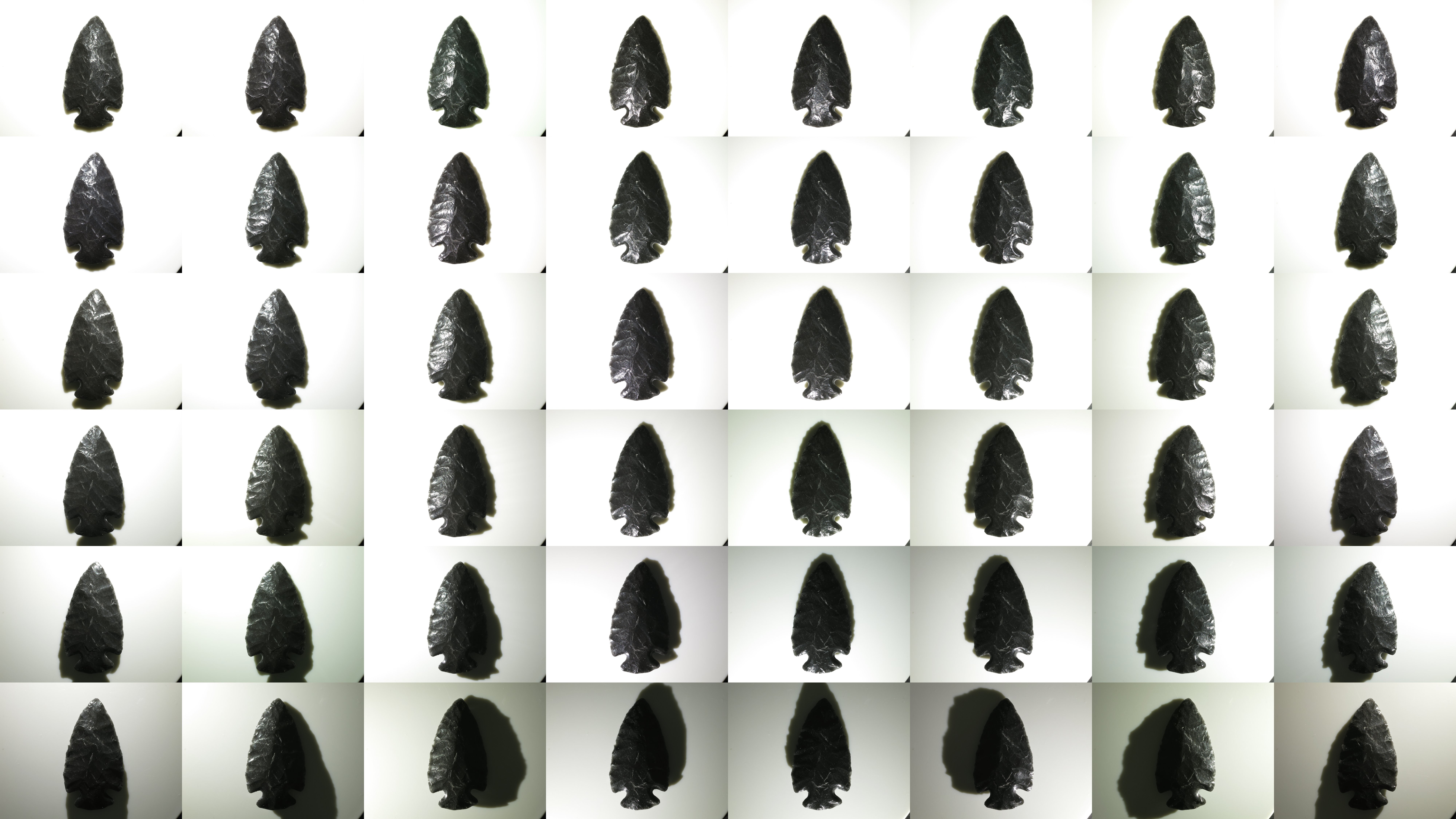
Here's a montage of all 48 photos taken of the sample artifact (a modern replica obsidian arrowhead) during the RTI dome system imaging run shown above; each photo was taken with a different LED lighting angle, and the camera in a fixed position looking straight down at the object:
![]()
These 48 photos are processed using free software into an RTI data file, which can then be interactively viewed and manipulated using the free RTIViewer software (available at the Cultural Heritage Imaging website). Here's a quick video demo of some of its features:
-
Tool Time
06/25/2016 at 18:44 • 0 commentsApologies to experienced makers - you probably have/know all of this. This project is potentially of use to many people that might not be makers (like archaeologists and paleontologists), so I'm throwing in a bit of background material on the toolset that's needed. The links are to show you examples of what you'll need (I don't usually own the ones I've linked to) - any equivalent to these tools will be fine.
Absolutely required
If you're going to build this RTI system, you'll definitely need the following tools: buy, beg, borrow or steal.
Soldering tools
The electronics are put together using soldering - for the most part, nothing fancy. If you've never soldered before, it's not that hard. Check YouTube for training videos on how to solder - some are very good. This Adafruit guide is worth a look.
Soldering iron - Don't need a super-fancy one, just make sure it has a point tip on it; I'd recommend 40W or higher, with controllable temperature. You don't want a soldering gun, or an iron with a large chisel tip, as these won't work well for the small-scale through-hole soldering you'll be doing. The linked soldering iron includes a few extras, including some items listed below. I own this one, a bit more control.
Solder - Get the thin stuff, 1 mm (.039") or smaller in diameter; easier to handle, and melts faster. Also make sure it's rosin core.
Brass tip cleaner / sponge tip cleaner for solder - Cleans oxide and unneeded solder of your soldering iron. I prefer the brass cleaner, but the wet sponges work as well.
Wiring tools
Wire stripper - No, the cheap one with the screw adjusted won't work. Get one with fixed holes for AWG wire diameters 22 to at least 26. I use the linked on, but there's a slightly cheaper one by a reputable maker at Digikey.
Flush cutter or diagonal cutter - Used for trimming electrical wires and part leads. The Hakko flush cutter works well and is cheaper, but the diagonal cutter works nearly as well, and you're likely to find it handier for other tasks in the future than the Hakko.
Needle-nose pliers - For inserting parts, bending wires, holding nuts.
Multimeter - Critical for testing the circuits, and measuring/calibrating the output current. Pick one that can handle currents up to at least 1 A (most do up to 10 A).
Alligator leads - Useful for connecting the multimeter to wires; also double as clamps for soldering.
General assembly tools
Crimper - Even with a small dome, you'll be crimping hundreds of Dupont pins, male and female. Technically you could do this with a pair of pliers, but after 50 or so crimps with pliers (and with multiple failures), you will start praying for death.
Electric drill, drill bits - No link for this one, hopefully you have one of these or know someone with one. Largest hole you may have to drill is 1/2" diameter.
1/8" acrylic drill - Acrylic plastic is a pain to drill with regular bits; you'll get lots of chipping, grabbing, and even breaking. This bit has a special design to help eliminate these issues. For larger holes, you can use regular bits after creating a started with this one; just gradually use bits of increasing size until you get to the final size.
Random tools (screwdriver, file, saw, etc.) - A whole bunch of random tools that you may need, but are pretty common.
Silicone adhesive - Used for attaching LEDs to the dome. You won't need a lot of it.
Safety glasses - 'Nuff said.
Optional, but helpful
Head magnifier - If you have young, good eyes, you may not need this. My eyes are old and decrepit, so this magnifier makes soldering and other fine work possible.
Solder sucker / solder wick - If you're a master solderer and never make mistakes, you may not need these - they help fix soldering problems by removing solder. I have both :). Check this video for more info.
Flux - Love this stuff; makes soldering problem connections a lot easier. Cleans off with rubbing alcohol.
Dremel or other rotary tool - Primarily useful for cutting holes in the controller enclosure, as well as general cutting/sanding/filing/milling. You can do all this stuff with other tools as well, it may just take longer.
Heat gun - Used for heat-shrink tubing in this build, special flexible tubing that shrinks when heated to insulate/protect/reinforce wire connections. I don't have a heat gun, but use a hair dryer on the hottest setting put right next to the heat shrink tubing; works, but a bit slow. A lighter or candle flame works on heat shrink tubing as well, as long as you're careful not to melt the tubing or set it on fire.
Anti-static wrist strap - Static discharge is bad in general for electronics, and the P-channel MOSFETs in particular are very static-sensitive. This wrist strap offers a level of protection from static discharge.
Step drill (aka Unibit) - The 1/8" acrylic drill listed above will be good enough for most of the holes you need to drill. However, there are a couple of holes in the dome that will need to be a bit larger. You can drill these by starting with the acrylic drill, and then gradually increasing the size of the drill bit you use until you reach the final size. If you skip too quickly to a larger size, you risk cracking or breaking the dome. A step drill has a conical shape with gradually increasing bit sizes in a single bit - you start with a smaller size, and gradually work your way up to a larger size. I've used these often on acrylic plastic, and as long as you start with a pre-drilled hole, you shouldn't have problems with cracking/breakage as long as you don't apply too much pressure while drilling.
I'm sure I'll think of more tools as I write up the build - watch this space.
-
Parts, Parts, Parts
06/21/2016 at 03:57 • 0 commentsWell, I think I've got the components list done. But wouldn't surprise me if I missed an item or two; will update on the project log if that happens. Just for reference purposes, I'll talk about elements of the components list here with a description of what every part is supposed to be used for; hopefully, that will make the design and assembly process more understandable. Check the original components list for required quantities.
A few comments on parts suppliers. For many of the discrete components, I link to a Tayda Electronics page. These guys have great prices on discrete components even in small quantities, they ship fast, and the shipping costs are very reasonable. For parts/items they don't have, I use Digikey - great service and fast shipping, but prices tend to be somewhat higher for many components. I also link to pages on eBay, AliExpress, Amazon and other vendors for various items not found on Tayda or Digikey. But feel free to use your own favorite vendor.
Three general categories: controller parts for the main control unit, dome parts for the RTI dome itself, and camera parts for the odds and ends that you'll need to connect your camera to the controller for automatic shutter control.
Controller parts
Arduino Mega 2560 R3 Controller - Main control unit. I've used several brands of less-expensive clones without problems. R3 is the most recent model, with the fastest processor, but if you have an older non-R3 unit, that will work as well.
Power supply - Any Arduino-compatible power supply should work, as long as it's rated for at least 2A current (9-12V OK but 9V recommended, 2.1mm x 5.5mm barrel jack, center-positive.
Battery power supply (optional) - Required for portable operation. Uses 6 AA alkaline batteries. The linked item already has a standard Arduino jack (2.1mm x 5.5mm barrel jack, center-positive), but you can certainly hack together your own as well. If you plan to use rechargeable NiMH batteries, you'll need a holder that takes 8 AA batteries, since NiMH batteries have lower voltages than AA (1.2V vs. 1.5V each).
Arduino Mega protoshield - A handy protoboard that plugs into the Arduino Mega, and has room on top to solder in the high-side driver components (albeit just barely). Make sure the one you buy looks like the one I link to.
11 x 8.5 cm protoboard - I highly recommend the one I link to, as it's cheap, the right size, and the metal goes all the way through the holes producing a secure solder hold. On cheaper protoboards, the metal is often just a little disk on top, and has a tendency to fall off.
10K linear taper potentiometers and knobs - Control the duration of the light, and the delay to allow the camera time to process and save the image before taking the next picture. 5K will work fine as well, and feel free to choose any style knobs you want.
Momentary push buttons (red and black) - Activate key functions, and one red button also resets the Arduino.
Toggle switches - Set options: sound on/off, manual/auto mode, shutter hardwire or IR/Bluetooth mode.
Red LED, panel LED holder, 560R resistor - For power indicator that hooks up to 8-12V power supply. I use a 560R resistor because 8 of those are needed for another purpose, and minimum resistor order from Tayda is 10. If you have a 470R resistor, you can use that instead.
USB Female A Panel Connector - Main jack for hardwired camera shutter connections, and also for the IR LED if you use a camera with LED remote capabilities.
Ethernet RJ-45 panel jack - The controller connects to the dome through Cat5E cables, which plug into these panel jacks.
RJ-45 Jack and breakout board - One RJ-45 jack is mounted internally, and the breakout board is needed to mount it to the protoboard.
CAT4101 LED Driver and breakout board - CAT4101s are the main switch/drive/current controller on the low side. They are surface-mount devices, so breakout boards are needed to use them on the through-hole protoboard.
0.1 uF disc capacitor - Use to suppress noise on input of CAT4101.
560R resistors and 5K trim potentiometers - CAT4101 use a resistor to set the desired currrent, with lower resistances yielding higher currents, up to 1 A max. The 560R resistor sets the maximum allowed current of 1 A; the trim pot is in series with that resistor, allowing you to set lower output currents if desired, as well as allowing you to fine-tune the output of all eight CAT4101s so that they match.
10K-ohm resistors - Used in several locations to limit currents.
IRF9540 P-Channel Power MOSFET - High-side switch to LED matrix; controls columns.
2N3904 NPN transistor - Controls IRF9540 MOSFETs.
Power strip protoboard - There are a lot of ground and +5V/+9V connections required, more than are available on the Arduino itself. The power strip protoboard adds extra female pin headers to accommodate those connections.
100 uF capacitor - Smooths out any major variations in the 9V input.
Piezoelectric buzzer - For audio feedback of several functions. Can be turned off in hardware or software.
Heat sinks (7mm x 7mm to 10mm x 10mm) - These probably aren't necessary. The MOSFETs are rated to operate continuously at up to 13A at 100C, and they will never see more than an amp for a few seconds at a time at much lower temps. The CAT4101 drivers will need to burn off more voltage, but even they won't be on for long periods, and have a thermal shutdown at 150C. Still, just to be safe, I use small heat sinks on both. I recommend getting heat sinks that come with tape adhesive in place - makes installation a lot easier.
Various headers - Used for wiring connections.
Dupont pins (male and female) - Used primarily for the LED wiring connections, but also in a few other locations. Housings needed for the female pins. If you live near the sea and corrosion is an issue, consider getting gold-plated Dupont pins, available on eBay; just slightly more expensive.
Black and red 22 AWG solid hookup wire - used for making connections inside the controller. Red and black to keep track of hot and ground connections, respectively. I say 10 ft. of each, which is probably more than you'll need, but it's cheap.
Black Kynar insulated 24 AWG solid wire - The main wire for connecting LEDs inside the dome, and protoboard interconnections. One 100-foot roll is probably enough for domes up to 24" in diameter; larger domes may require a second roll.
The next set of parts is for the enclosure that will hold the electronics, and into which will be installed switches, pots, LEDs, panel jacks, etc. Feel free to design and construct your own, using my model as an example.
Plastic enclosure box - This was the only pre-made one I could find that was big enough to hold everything. It's a nice box, but kind of expensive- shipping almost doubles the price.
Rubber feet - To put on the bottom of the enclosure box, to keep it from sliding around,
Mixed nuts, washers, bolts, screws, spacers - Attach the main control electronics to the box.
RTI Dome Parts
What you need to build the RTI dome, to light up the object from multiple angles and take photographs through the top.
Dome - I've already posted here and here on what's required for your dome. Deviate from these recommendations at your own peril.
Flat/matte black spray paint for plastic - Used to cover the inside of the dome, to minimize scattered light from the interior. Make sure whatever black paint you choose dries with a "flat" or "matte" non-reflective finish - avoid "satin" finishes, and "glossy" is totally unacceptable. Also make sure the paint is specified as working with plastics. I found Rustoleum works best; Krylon also works, but requires more coats.
Black reflective sphere - This will be used to calibrate the dome LED positions. I reference a high-quality silicon nitride bearing, but any decent black reflective sphere will work. This includes black marbles, stainless steel ball bearings dipped in black ink, or obsidian spheres for larger systems. For proper calibration, the sphere must have a diameter of at least 250 pixels when photographed from the top of the dome.
LEDs - The system was designed to handle up to 3W LEDs mounted on star bases for heat sinking. I highly recommend Cree LEDs, and I also highly recommend buying from a reputable source. I made the mistake of buying "Cree" LEDs at bargain prices from Chinese vendors, which suffered from non-uniform intensities and wildly varying color balances. Official Cree LEDs are binned to match fairly closely in intensity and color balance. My vendor of choice is LED Supply - decent prices, volume discounts, and they ship quickly. Buy a few more than the minimum you need, in case you have problems in assembly, or wind up with a bum LED or two. New models of LED come out on a regular basis - my current choice is the 3W neutral white XP-E2 variety, 1up star. For domes 12-14" diameter, I recommend no more than 48 LEDs; 15-17", 56 LEDs; 18" and up, 64 LEDs (the maximum number the controller can handle).
2mm heat shrink tubing - To insulate LED wiring connections.
Cat5e 24 AWG Ethernet patch cables - These are used to connect the dome to the controller. I spec 24 AWG to maximize the current capacity and reduce resistive heating - I've run 1 A through the individual wire strands continuously for up to an hour without any significant heating. Monoprice is an awesome source for these, as well as any additional USB cables you might need. I spec 5 ft., but choose a longer length if you want more flexibility; you'll be cutting one end off of these, so you can always shorten them if necessary during the system build. I strongly recommend that one of the cables you buy be red, to be designated as the positive/high connection to the dome. For the other cable, pick any other color - I usually choose a color to match the dome (black or white for all the ones I've built to date).
4" cable/zip ties - Used to tidy up cables inside the dome. Available everywhere; I usually pick a color that matches the exterior of my dome.
Camera cables
If you haven't already, read my log on camera considerations for additional background on these parts. I highly recommend Monoprice for all your USB cable needs.
Canon camera with CHDK:
All you need is the standard USB cable that plugs into the camera on one end, a female USB jack on the other. Depending on your configuration, you may want to get a longer cable, or a USB extension cable.
Camera with IR remote capability:
USB cable
Assembly is easy - just wire the resistor in series with the LED, connect to the USB cable; more complete instructions down the road. Software supports cameras made by Canon, Nikon, Olympus, Pentax, Sony, and Minolta that have IR remote capability. I recommend this option heartily for any camera that supports IR remote; cheapest, easiest and most flexible option.
Camera with hardwired remote capability:
Remote connector plug compatible with your camera. You may have to buy a cheap hardwired remote on eBay or Amazon, and then cut off the connector plug.
USB cable
More explicit instructions down the road.
Dome stand
I'll cover this in a separate post - lots of options here, as well as the freedom to set it up anyway you want.
-
Design Considerations, or A Design History
06/18/2016 at 05:26 • 0 commentsThis is just a quick explanation of the basic LED power control system I use in my RTI controller. You might find it useful in understanding how things work, and I hope it's not too technical; but you don't have to understand this to build the system.
I first started working on this project early in 2013. I knew the control system would be driven by an Arduino, since the control requirements were pretty basic - turn lights on and off, fire a camera shutter in sync with the lights. But while an Arduino Mega has enough pins to control an adequate number of LEDs to do RTI (around 50+), wiring those pins individually to LEDs would be a nightmare. And in any case the Arduino wasn't going to be adequate as a power source to light up the LEDs - the maximum current any Arduino pin can safely supply is 40 mA, with 20 mA the recommended maximum for continuous output. That means about 100 mW of power at best, which would have limited me to small domes and long camera exposure times. What's more, for good control of LED light intensity, critical for good RTI results, you need to control LED current accurately.
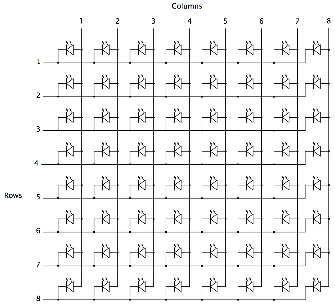
The solution to the first problem is to wire up the LED lights in matrix format:
Here's an 8x8 LED matrix diagram , with 64 LEDs in total. To turn on a single LED, you need to activate the appropriate electrical connections for the matching row and column, high-side voltage for the columns, low-side for the rows. For example, activating Column 4 and Row 5 lights up only the 4th LED in the 5th row. Running sequentially through rows and columns, every light can be turned on just once. This requires control of only 16 Arduino output pins.![]()
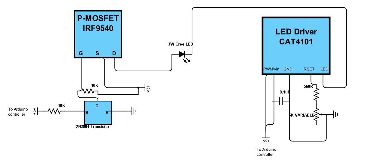
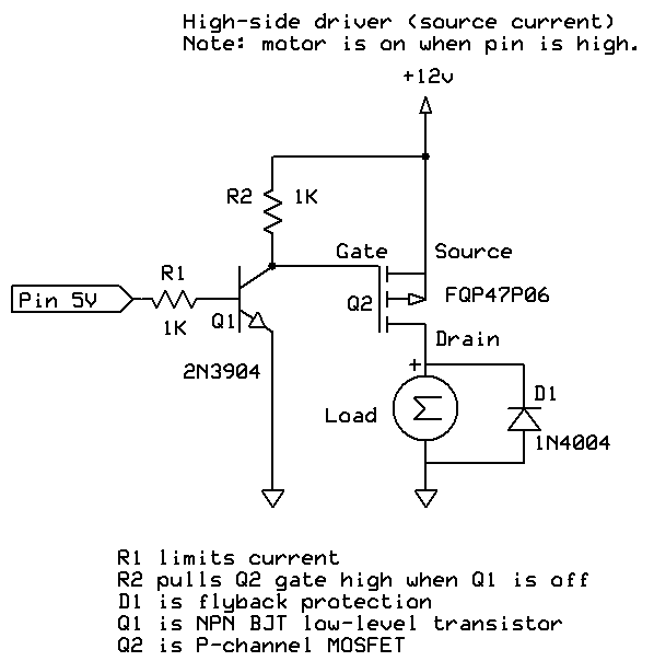
The second problem, high and accurate LED currents, requires circuitry on both the high and low sides of the LED. Here's the solution I came up with:
Sorry about the crummy schematic - most of mine are hand-drawn. On the left is a standard high-side P-channel MOSFET driver layout, which is easily found on the Internet (e.g. here and here). I originally used a single-chip high-side Darlington array with 8 channels, but the maximum current was only 350 mA, resulting in LED light intensities that were still a bit dimmer than what I wanted; P-Channel MOSFETs can handle much higher currents, even though I had to now use 8 of them. The P-Channel MOSFET controls on/off for the LED power supply, shown as +12V, but which normally runs at +9V, and can run +8-12V. The connection from +12V through the 10K resistor to the Gate is required because P-channel MOSFETs are on when the Gate is unbiased, so a voltage equal to the Source-Drain bias voltage needs to be applied to keep the MOSFET normally turned off. When +5V is applied from an Arduino controller output pin to the base of the 2N3904 transistor, it turns that transistor on, which shunts the +12V voltage away from the gate and turns on the P-MOSFET supply voltage to the LED. Check out the links above for a more coherent explanation. Below is a better schematic of the high-side driver from the first site linked above; the "Load" in this case is an LED, and there's no need for a flyback protection diode. I use IRF9540 P-Channel MOSFETs because they're cheap, and work fine, but an FQP27P06, FQ47P06, or NDP6020P P-Channel MOSFET would work just as well. You just need a P-channel MOSFET that can handle high currents, and has a low Rds.![]()
![]()
On the right-side of my schematic is the low-side driver/control, a CAT4101 LED driver that not only switches on and off the low (ground) side, but allows you to set a desired current between 150 mA and 1 A. This is a 5-pin chip. The first pin, EN/PWM, switches on the LED and can control intensity through Pulse Width Modulation; the 2nd pin, Vin, supplies +5V of power to the chip. I have these two pins bridged in my control system, so that the same Arduino controller pin both switches the chip on and supplies power. I did this because leaving all of the CAT4101 chips powered on continuously led to some weird issues with multiple LEDs turning on even when only one should have. The GND pin goes to ground. RSET connects to resistors that set the output current, with 560R giving you about 1 A, the maximum. The 5K variable resistor lets you fine-tune the current to allow for variations between different chips, and also allows you to set currents lower than the max 1A. This is useful for extending the life of the LEDs by keeping them from overheating, and also in certain use cases. For example, I sometimes use USB microscopes for micro-RTI, and full LED intensity is usually too bright for those; if I turn the current down to 150 mA, then there's no problem with sensor saturation. Finally, the LED pin connects to the ground side of the LED.
The schematic shows one high-side and one low-side driver, connected to one LED. But in the control system, there are eight high-side drivers, each connected to a column in the LED matrix, and 8 low-side drivers/constant current controls, each connected to a row in the matrix. Each driver is connect to an Arduino controller output pin that can turn it on and off as needed in software. This setup can drive a Cree 3W LED to its full power limit, at a current of 1 A.
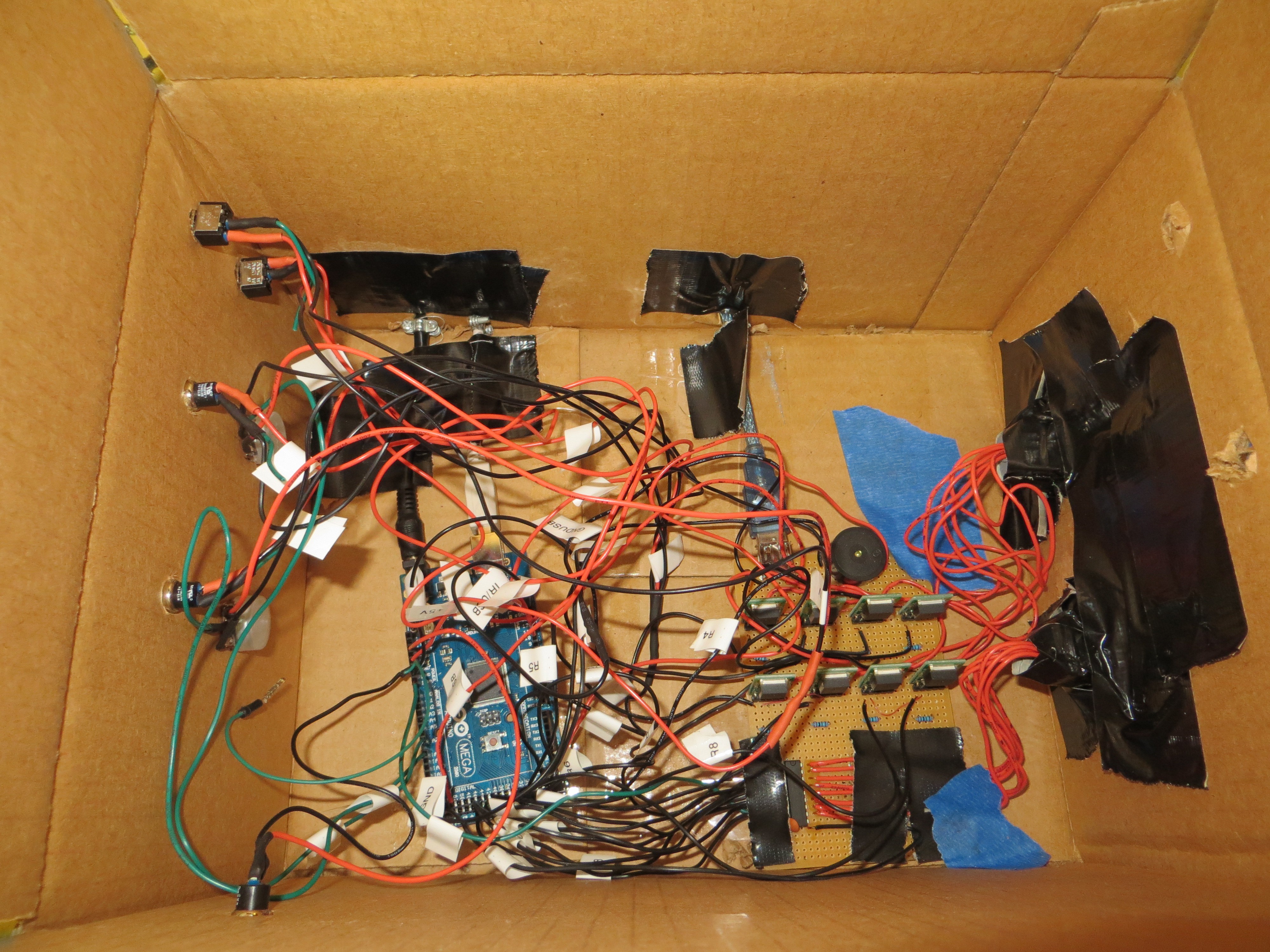
Just for laughs, here's the inside of my original controller box from 2013, using a Darlington array :
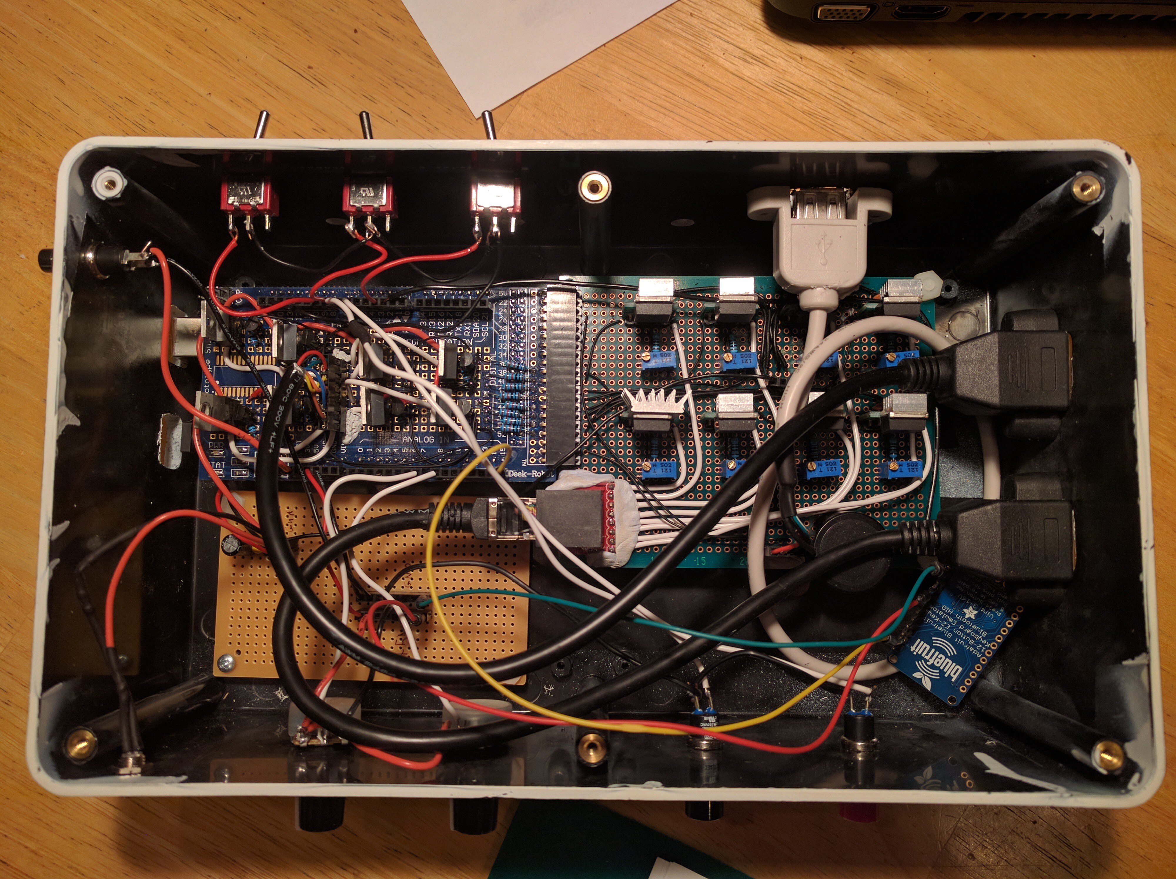
And here's the most recent version I've built, the prototype for the system I'm describing on these project pages:![]()
P-Channel MOSFETs on the left, CAT4101 chips on the right.![]()
Affordable Reflectance Transformation Imaging Dome
A simple and inexpensive way to image and analyze subtle surface details on objects.