-
Component Layout
05/30/2016 at 13:19 • 0 commentsWhen working out the component layout, one of my major goals was for this project to be compact and pocket-sized. Therefore, as a rough guide, I figured that it shouldn't be larger than a phone.
![]()
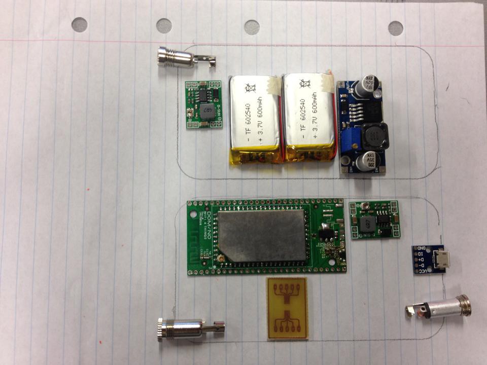
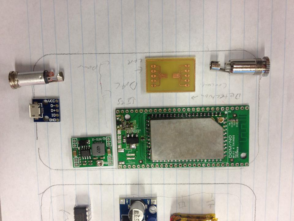
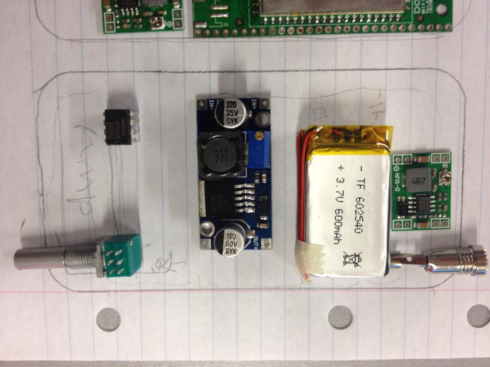
I started by drawing the outline of my phone and trying to place the components within it. Looking at the schematic, it made sense to put all the power supply and amplifier components in one section, and have a separate section for the ICs and audio jacks. Since the parts are all very thin (with the minor exception of the boost converter), I separated them into two layers.
![]()
![]()
I tried out a number of different arrangements, trying to make parts linked in the circuit diagram close together.
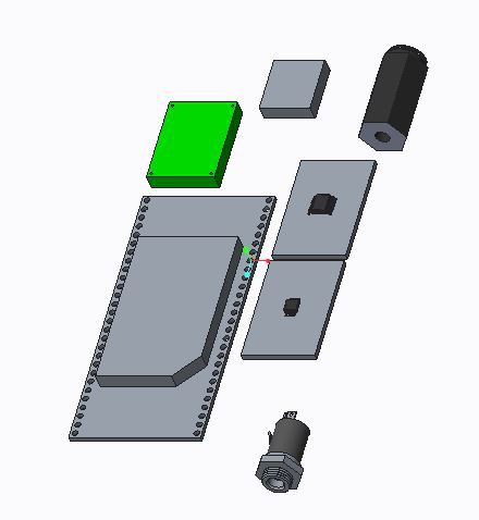
Finally, I modeled the arrangement using CAD. For this application, I used PTC Creo. I made sure that the outside dimensions were correct, to ensure that there would be no collisions, but I did not produce parts with fine-detail. Where possible, I used the manufacturers' CAD models available online.
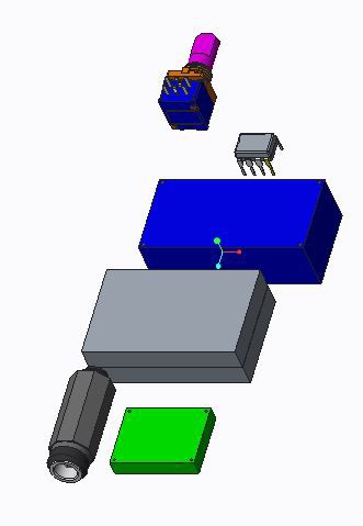
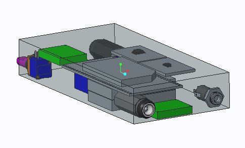
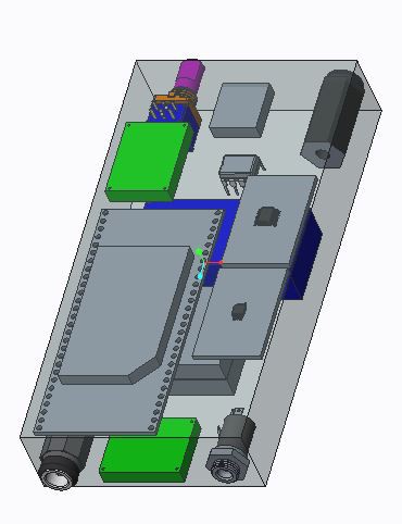
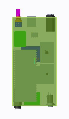
This is the layout of the top layer. This consists of the single-board computer, voltage regulator (green) supplying 5V, the DAC and Audio Switch ICs on breakout boards, the micro USB port for digital audio in and the two 3.5mm audio jacks. One (at the top of the picture) for audio out and the lower one for bypassing the digital stages and using the amplifier directly. Space has also been to implement the detection circuit.
The bottom layer contains the barrel connector for charging and external power supply, a voltage regulator (4.2V), two batteries stacked on top each other, the boost converter (in blue) and the amplifier components: the volume control dual potentiometer and the op-amp.
The final series of combined assembly images should make it easier to place the components in the pocket-sized enclosure during manufacture.
-
Circuit Schematics
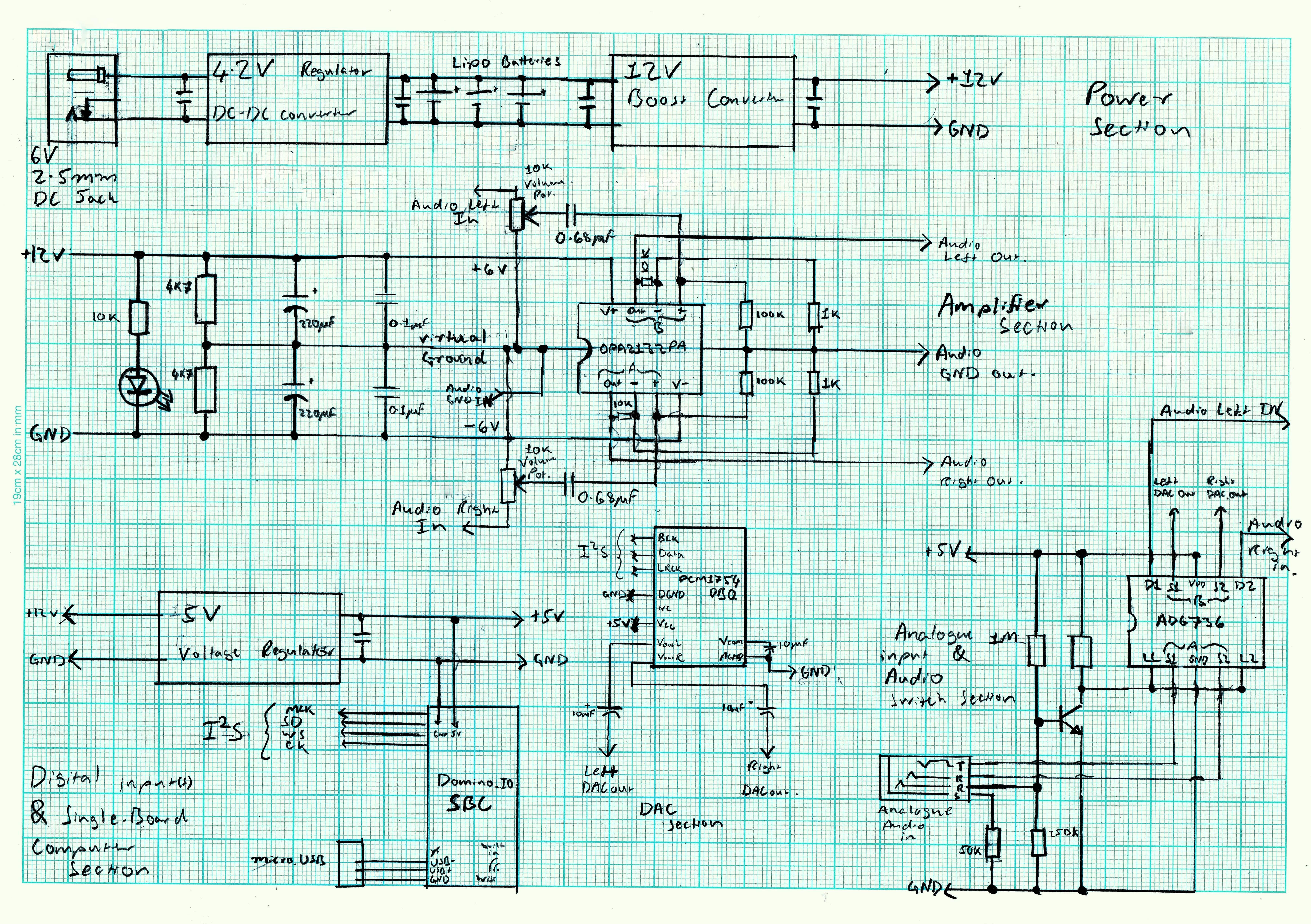
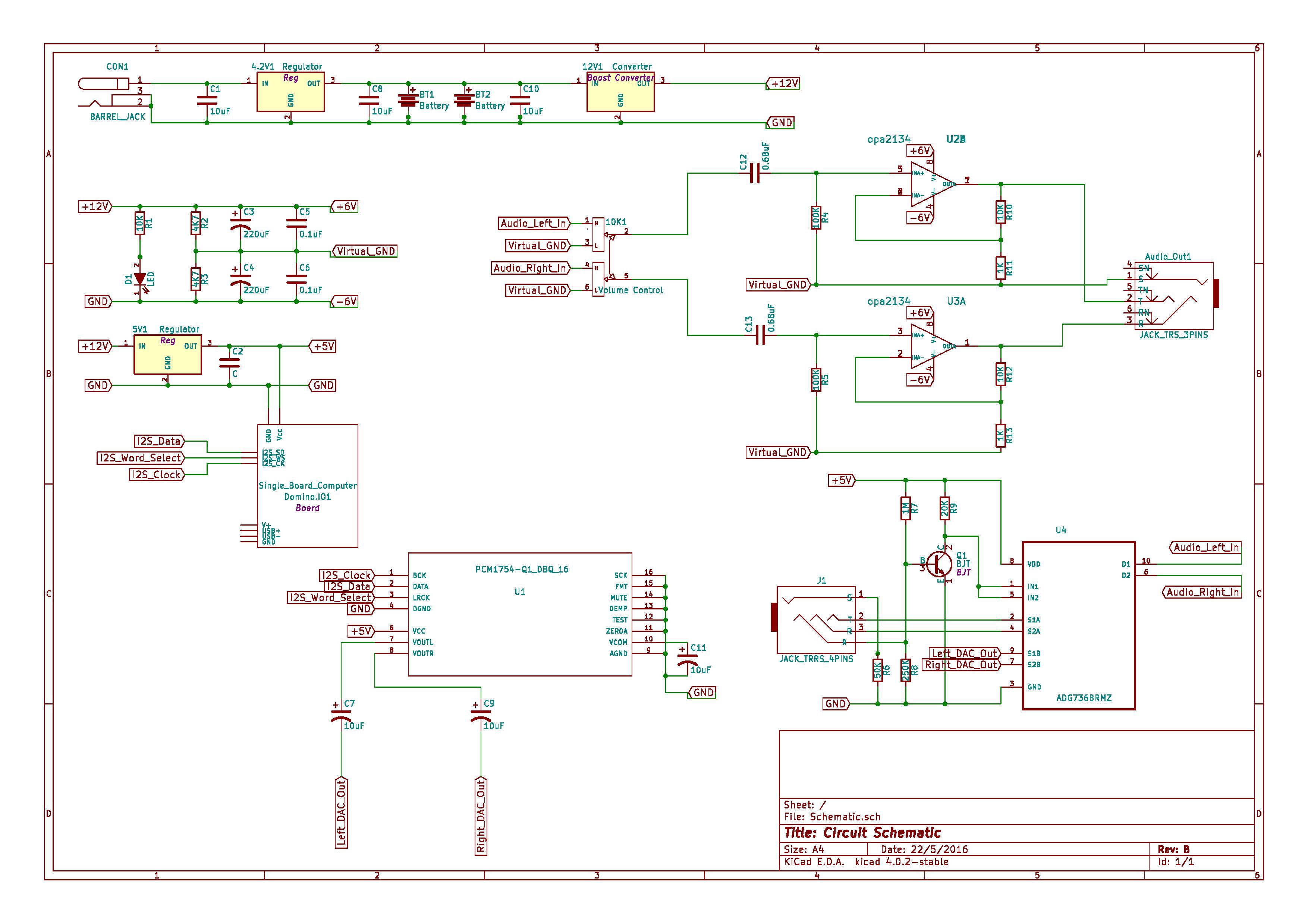
05/30/2016 at 01:40 • 0 comments![]()
I drew up the circuit schematic using the layout of the ICs I am going to use. I then used this sketch as a reference to make a schematic on KiCad. Some of the KiCad footprints are not the same as the actual components though, so I'm uploading both schematics
![]()
-
Component Selection
05/29/2016 at 23:28 • 0 commentsThe computer I selected for this project was the Domino.IO Core, mainly because it shipped very quickly and was readily available. This computer was short-listed because it has a very small form-factor and low power usage making it great for portable battery powered operation. It also has built-in Wi-Fi, so there's no need for additional modules as well as I2S for transmitting digital audio signals. Another added benefit is that the boards it can be mounted on are open hardware. Unfortunately the computer itself is not open source. However, it may be replaced with any other Linux based Single-Board Computer with very little change in design.
The DAC selected was the PCM1754DBQ. It has a high sampling rate (up to 192 kSPS) and a sufficiently high bit-rate (24 bit) for high quality audio reproduction. It can also be directly connected to the SBC through I2S.
For the audio switching, the ADG736 SPDT audio switch was chosen because it has a low resistance and is able to switch bi-directional current (essential for switching analog signals).
Finally, I decided to go with a CMoy amplifier design. It's a very compact and easy design to implement, and there's tons of resources available to design it, such as the tangentsoft website. This website provides all the information required to build the amplifier and ensure it's running correctly, making the design ideal for getting the project up and running. This may be easily replaced with a more advanced amplifier at a later date. I decided to use the Burr-Brown OPA2132PA op-amp to implement this amplifier, but there's a wide selection available with their own unique sounds and features.
While researching amplifier circuits, I came across an awesome CMoy amplifier using P2P wiring. Given that I don't really have access to any PCB manufacturing equipment and I want to limit the cost of the build, I decided to use some P2P wiring myself. Also I reckon it looks pretty cool.
-
Design Plan
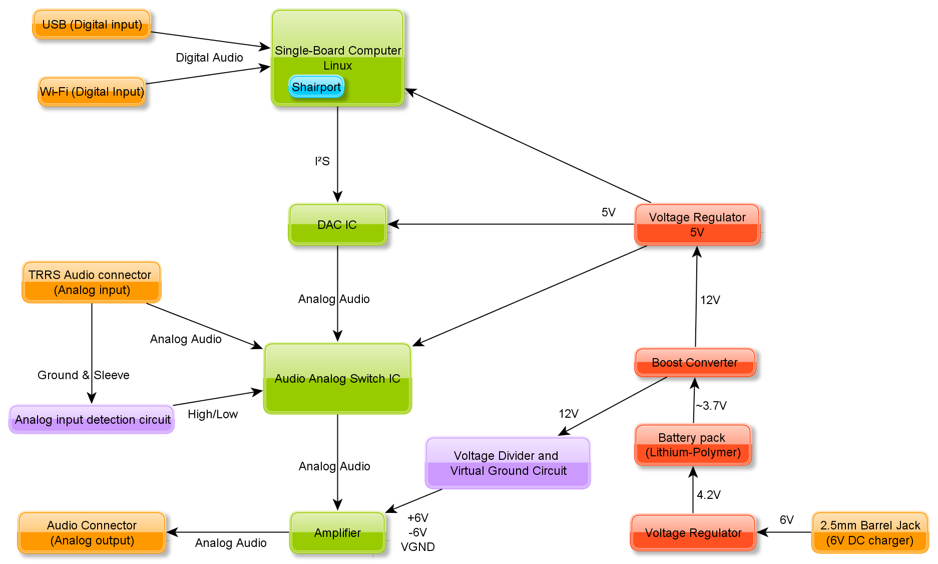
05/29/2016 at 20:24 • 0 commentsI made this diagram to help plan out the design and visualize the components required.
![]()
In order to get the Single-Board Computer to connect to the audio source, I am planning on using Shairport. The Shairport package allows audio to be played through Wi-Fi using AirPlay sources and iOS devices.
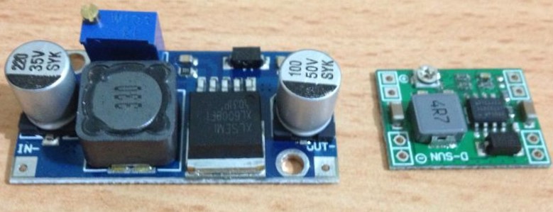
Since I want this system to be light and portable, I'll use lithium-polymer batteries in parallel. They can be made very thin and light and I already have a few small ones lying around. These types of batteries can be dangerous if not properly maintained though. Initially, I was planning on using several in series to get a high enough voltage for an amplifier circuit, but the issues with balancing their charges meant an overly complicated circuit. Instead, I'm going to use a reasonably cheap adjustable boost converter board to step-up the voltage (blue board in image below). The board I'm using has a switching frequency around 400 kHz which is way higher than human hearing, so noise shouldn't be a problem.
![]()
For simplicity, I'll charge the lithium-polymer batteries using a constant voltage of 4.2V. This can be obtained from an old 6V DC wall wart and an adjustable switching voltage regulator (green board in image above). Another regulator can be used to get the 5V required for the ICs.
In order to get the most out of the device, I want to add the option of running analog audio through the amplifier bypassing the SBC and DAC. This means that the amplifier can still be used with a source that has a headphone jack. Instead of a switch, I wan to use a 4-pole audio jack (TRRS) to determine if an analog cable has been attached or not and switch the signals accordingly.
![]()
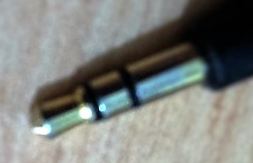
This is the jack from the pair of headphones. The tip provides the left signal, the ring in the middle provides the right signal and the sleeve is the common (ground). A TRRS jack has an additional ring, which is generally used for a microphone. However this can also be used to detect if a plug is inserted, as it will connect the second ring to the common. This will change the resistance significantly, which can be used to provide switching logic to an IC.
Portable Wi-Fi DAC & Amplifier
This project will allow for the transmission of high quality audio, which isn't possible through Bluetooth, to speakers and headphones
