-
Average positions
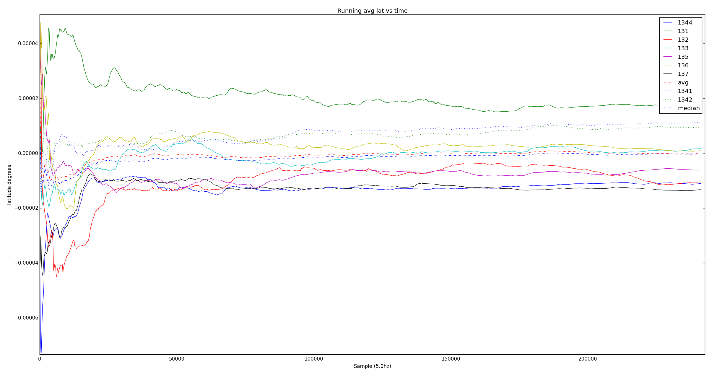
06/01/2016 at 23:28 • 0 commentsAnthony posted a question about averaging the positions for each receiver and comparing them to the overall average, and checking whether the grouping gets tighter. I hadn't checked that yet, but a few plots later, here is a running average of each receiver with 0 being the average of all data.
![]() The data stabilizes over the first hour or two but there are consistent offsets between receivers that I think are from reflections since the data was collected indoors. Since each receiver seems to be stabilizing to its own offset the averages get closer but only up to some limit.
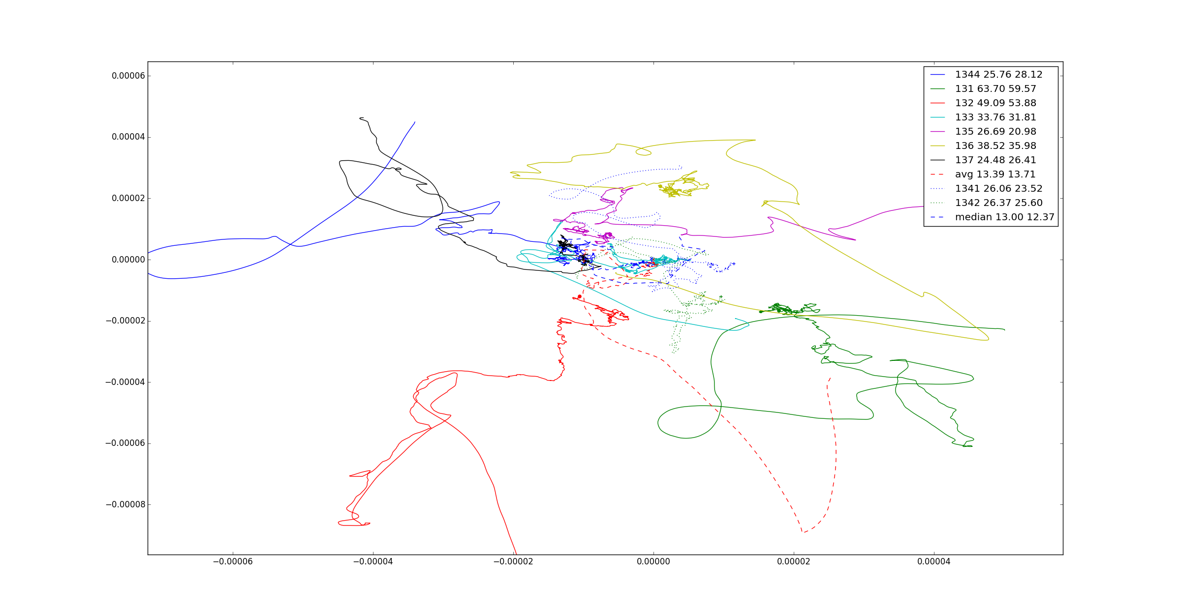
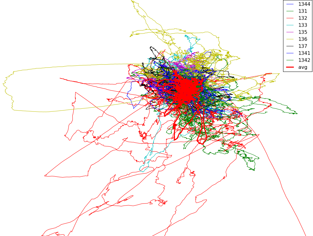
The data stabilizes over the first hour or two but there are consistent offsets between receivers that I think are from reflections since the data was collected indoors. Since each receiver seems to be stabilizing to its own offset the averages get closer but only up to some limit.Here is a 2d plot showing latitude and longitude, again with the running average. There is a dot at the final position of each path and the overall average ends at (0,0).
The numbers are receiver port# then standard deviation *1e6 for latitude and longitude.
Interestingly taking the median of the receiver's positions has a lower standard deviation than the average. For a true Gaussian distribution the average should be better.![]()
-
11 serial ports with PSoC5
05/30/2016 at 07:59 • 2 commentsI'm using the CY8CKIT059 PSoC 5 LP Prototyping Kit. ($9.98 from Digikey).
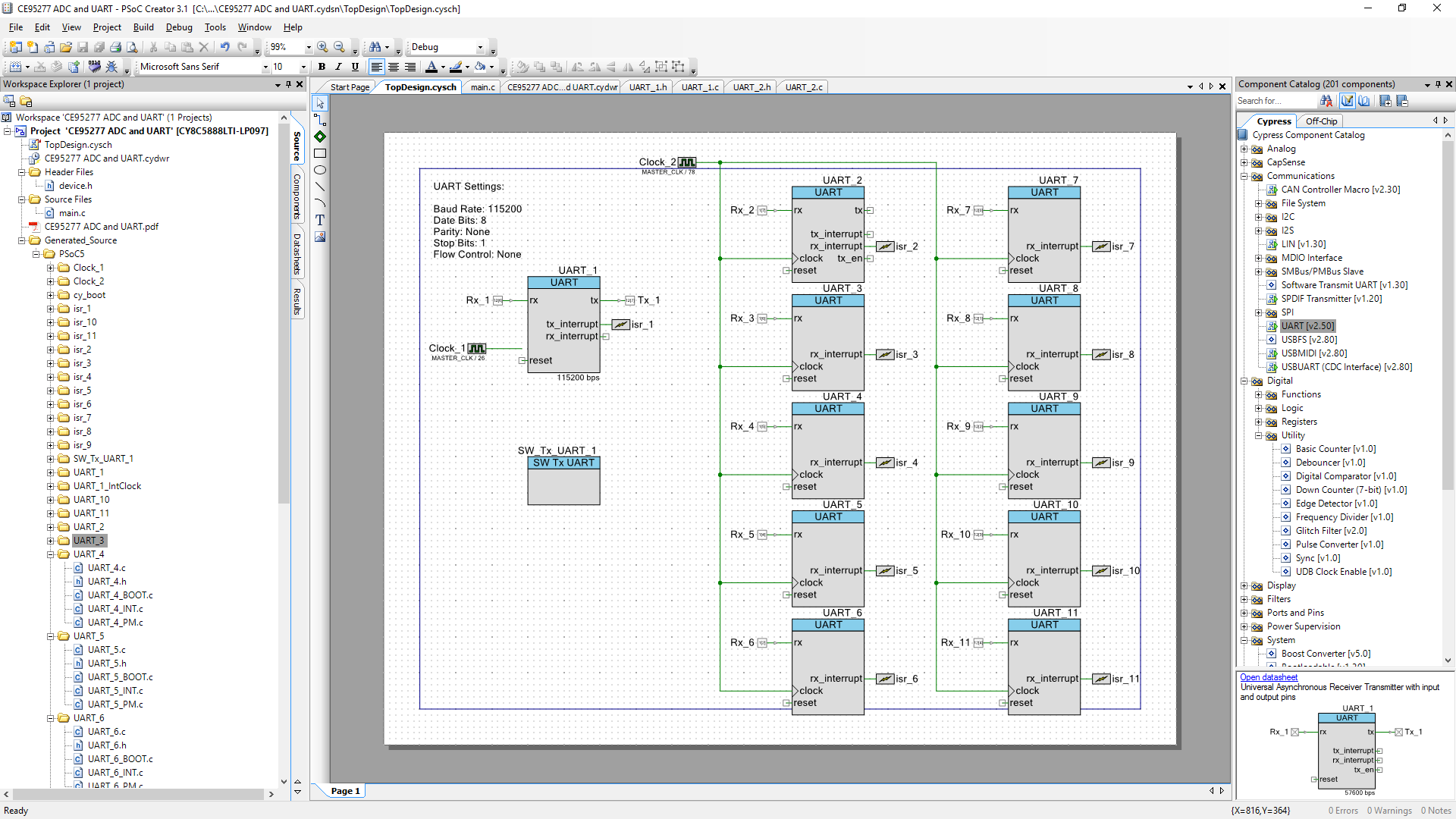
I first tried the PsoC5 on Friday to make sure I could fit 10 serial ports. My first impression is that Psoc is surprisingly capable but also very unusual. It mixes programmable digital (small FPGA), programmable analog, and an ARM Cortex and integrates them all surprisingly cleanly in the PSoC Creator IDE.
I was able to fit 11 receive and two transmit ports in hardware. The first limit I hit was on the number of clocks, at 8 as I recall, but serial ports can use any external clock source you route to them so I shared one clock for 10 ports since all the GPS modules should use the same settings. Next, I hit the limit of the number of UDB status cells so I made most of the ports receive only. There is also the option for transmitting using software serial so it is possible to transmit on any IO pin.
Originally I wanted to use the USB CDC serial but it uses more UDB status cells than a serial port, so using the programmer part of the CY8CKIT059 is good enough. It also makes it easier to integrate with something expecting a normal gps over serial since the programmer can be broken off leaving tx/rx/gnd/power at the pins on the edge of the PsoC target board.
![]()
I had some issues with the documentation about the serial port component and extending the buffer size to avoid overruns when receiving data faster than it ca be processed. The serial port has a 4 byte FIFO by default, but can be set to move data to a larger buffer automatically with interrupts. Since it was built in I expected it to “just work” when I enabled it but you need to connect an ISR to the interrupt of the serial component. Apparently creating them on the top design schematic and connecting it is enough for it to call the correct ISR to handle the data. I might also be wrong and I just needed to call CyGlobalIntEnable; in the start of main() for it to work.
One complaint is that PSoC doesn't support C++ by default although you can add a compiler flag per file to force it. Hopefully Cypress will fix this soon.
I plan to process the data on the PSoC but for now it just aggregates the data and sends it out the serial port to the host. Each packet identifies the source and number of bytes, sending data from whichever port has the most data waiting so latency is minimized when possible. With reasonably sized buffers and the interrupts enabled there was no lost data when receiving on multiple serial ports.
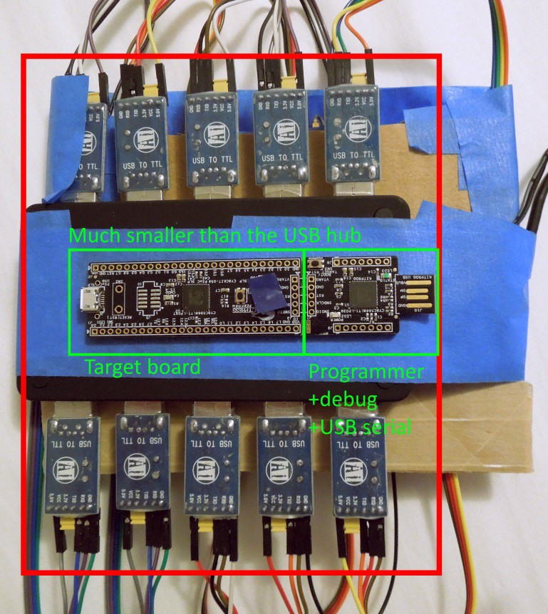
The PSoC board is much smaller than the USB hub and USB-serial converters and should be very portable. 9 GPS modules and the PSOC should fit in a 10x10cm square.
![]()
-
A (slightly) better GPS Jammer
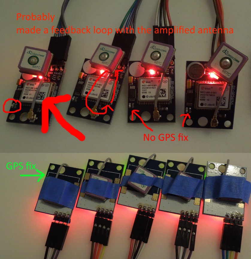
05/30/2016 at 07:21 • 0 commentsTo make all 10 modules fit in a tighter space I rotated the antenna cable so the antenna was on top of the board and going over the metal enclosure of the u-blox module. It turns out this is a bad idea.
![]()
The modules like this won't get a fix and sometimes nearby modules with the antenna in the previous position will also lose their GPS fix.
Flipping the antenna to the back of the board seems to be OK, and it looks like the solder pads might have been designed so a 25mm antenna could be soldered on.
-
Working prototype
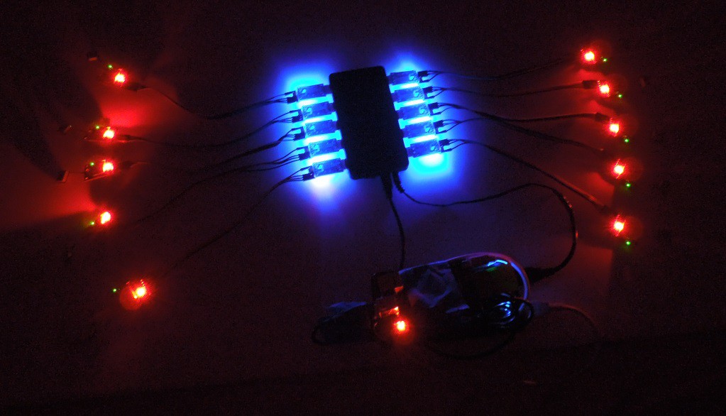
05/30/2016 at 07:05 • 0 commentsRepeating the first test but with CH340G USB to serial modules was successful. I was able to collect data and verify that the GPS modules position errors are mostly uncorrelated. All receivers are using the pedestrian motion model which is usually used for quadcopters and mobile robots. Data is being collected by a raspberry pi powered by a battery. They are taped together with blue painter's tape. The green lights are the blinking 1hz gps fix indicators.
![]()
For unknown reasons some of the modules performed much better than others. Standard deviations of ECEF coordinates for stationary receivers:
port#
131 std dev ecef xyz: 4.36733961451 5.38598533829 4.63016919654 count 25035
132 std dev ecef xyz: 5.61831775208 7.69243409578 9.95405542263 count 25034
133 std dev ecef xyz: 2.55442495355 3.82986851158 4.51910378608 count 25034
135 std dev ecef xyz: 2.12149753735 3.89156985078 3.78189588556 count 25033 M8N
136 std dev ecef xyz: 4.99567494154 5.33529922458 6.16849375111 count 25034 NEO 6 with battery
137 std dev ecef xyz: 2.82344410311 3.11478701186 3.80990062098 count 25034
1341 std dev ecef xyz: 2.34334818397 2.35146659893 2.87943477633 count 25035
1342 std dev ecef xyz: 1.994791898 3.09545183575 3.3114030156 count 25034
1344 std dev ecef xyz: 2.18281292001 3.1387471586 4.3756498617 count 25035
* One usb connector was loose and no data was recorded, it was omitted. So only 9 are being used
avg std dev ecef xyz: 1.15707392873 1.72618783161 2.03612534098 count 25033
Since the errors are partially correlated the result isn't as good as 1/3, but it has about half the error of any single receiver which would be expected from four which were uncorrelated.
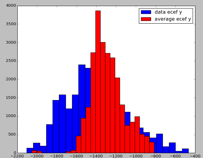
A histogram shows that the distribution of the averaged receivers is tighter than a single receiver.
![]()
Since the data was taken indoors the deviation is quite large (the histogram is in cm matching the raw data from the GPS receiver). I forget why it is all shifted negative in the picture here.
This blob covers about 30m. Outdoors with line of sight to satellites it should be significantly better.
![]()
In conclusion, it basically works.
-
GPS Jammers?
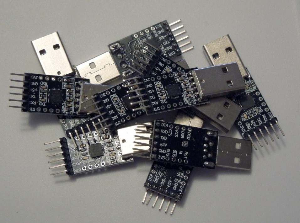
05/30/2016 at 05:01 • 0 commentsFor the first test I tried attaching 10 GPS modules (9 GY-GPS6MV1, one GY-GPSv3-NEO M8N) using 10 “CP2102 USB 2.0 to UART TTL 6PIN Module Serial Converter” from ebay on BalanceFrom 10 port USB hub.
![]()
Everything looked fine at first with the green GPS fix lights turning on one by one on all 10 modules. So, I started a script that opens all serial ports and logs the data, and after a few seconds the GPS fix lights started going out, blinking back on, then mostly being off. Repeating it a few times confirmed that whenever I open the serial port to read data the GPS fix quickly degrades to 2d then no fix. For a sanity check I connected a Teensy 2.0 board using the USB-Serial sketch and everything worked fine. The USB-serial modules seem to be jamming the GPS. Testing more showed that the interference seems to be strongest for the module connected directly to the converter but nearby GPS modules also had some problems.
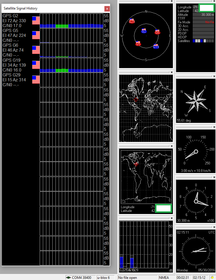
Testing with ublox u-center shows that the signal strength is very low and it keeps losing the GPS fix.
![]()
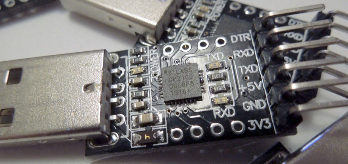
Since I did buy the CP2102 serial converters on eBay the chips might be counterfeit, or the board may have bad EMI properties. I'd really like to investigate more but I don't have time at the moment.
![]()