Kyle Gabriel
-
Power Output and Mounting Options
07/19/2016 at 00:18 • 0 commentsToday I'm building a simple outlet array, mounting it to the controller, and mounting the whole unit on a stand.
Until now, I've been relying on a bar stool to support the controller box and sensors. While not being sturdy, it also prevents the power outlets from being installed.
![]()
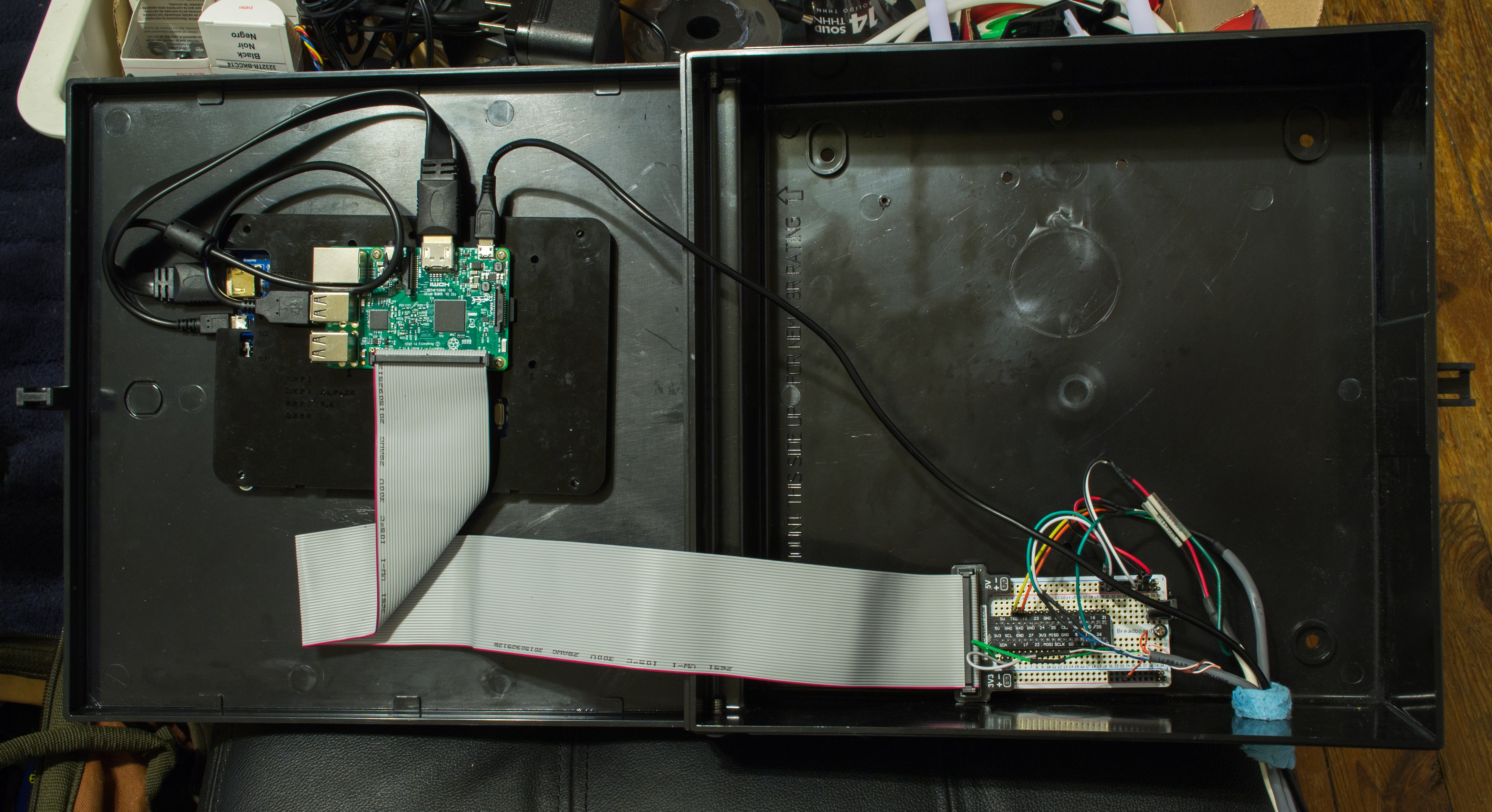
Here's a shot inside the box. There's a lot of free space. Here you can see the Raspberry Pi attached to the back of the LCD, with an IDE cable running to the breakout board that's soldered to the breadboard-style PCB. The wires coming into the box are various sensors.
![]()
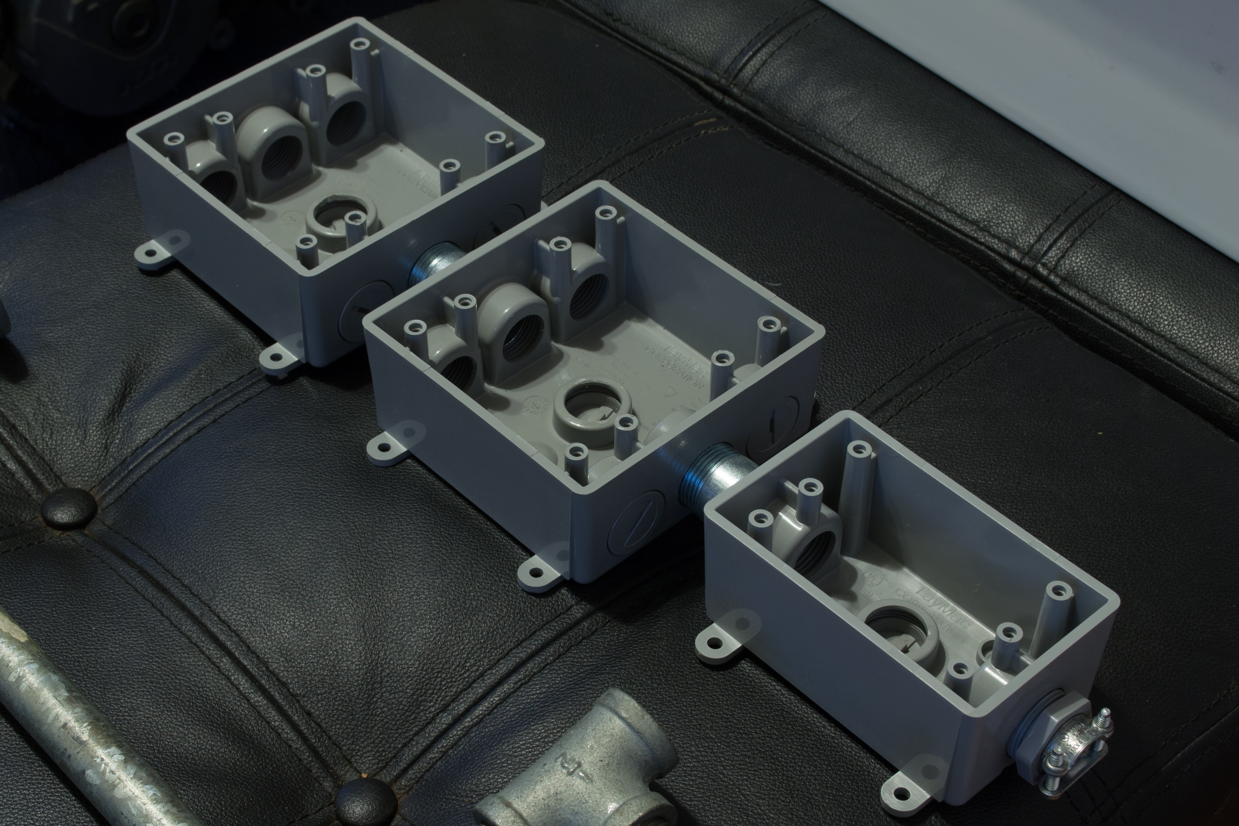
This is the solution I came up with to have both a diverse set of plug configurations (some power strips are too close and certain plugs cannot fit together) and modularity (easily add and remove outlets).
![]()
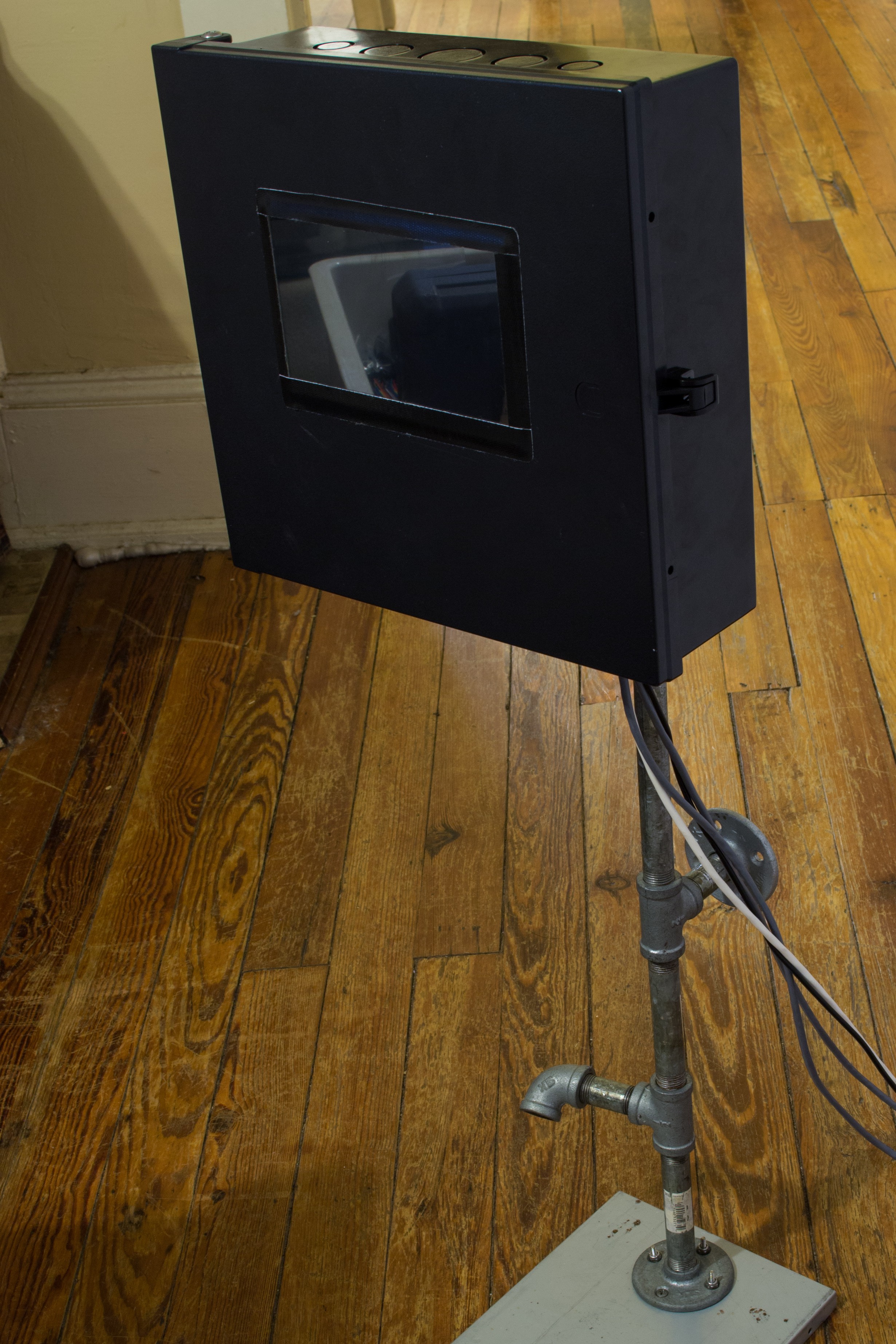
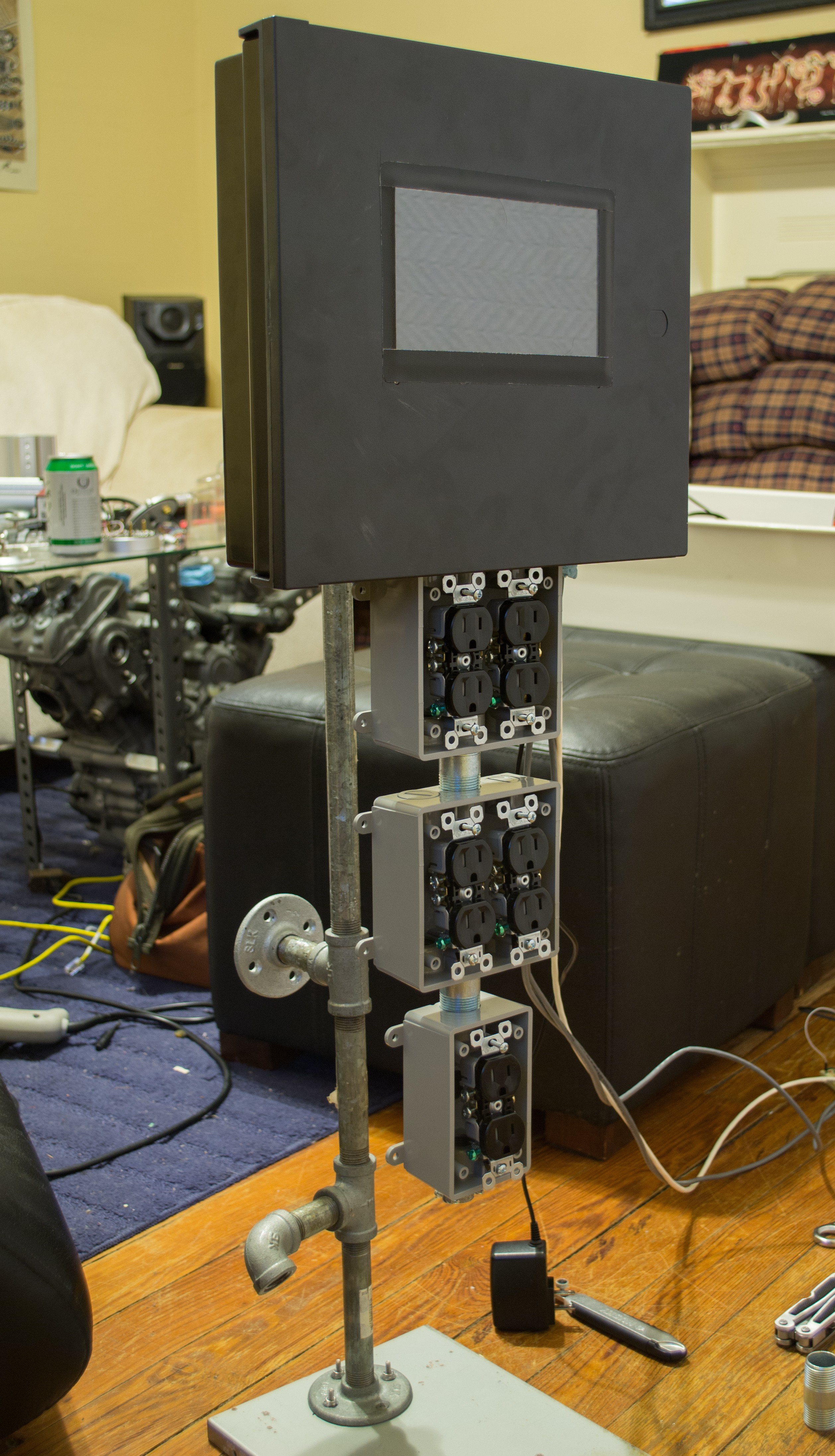
I happened to have a bunch of free pipe fittings I've been wanting to do something with. I'm not even sure where the metal base plate once came from, but it allowed me to make a fairly stable stand. Both the box and plate were secured with nuts and bolts.
![]()
And with the outlet array mounted, it's starting to look like something. Whether it looks good or bad is debatable. To mount them together, I used an old motorcycle sprocket lock washer and one of the reducing pieces that came with the outlet boxes. The union went through the washer, then through the electrical box, and screwed into the outlet box, securing them together.
![]()
Next will be the installation of wiring, relays, and maybe testing a fully-operational system. I'll end this build with a better shot of the front touchscreen LCD.
![]()
-
The Shell and Touch Display
07/14/2016 at 04:17 • 0 commentsThis build log will cover the construction of a hardware enclosure that has both a 7" touchsceen LCD display (1024x600 native) and switched outlets integrated into the unit.
Today's segment will cover installing the LCD, Raspberry Pi, power/signal distribution PCB construction, and sensor hookup. By the end of this session, we will have a Mycodo system reading and logging sensor measurements, but we won't yet have relays installed to actually have some fun controlling things.
The front of a 11"x11"x3.5" plastic enclosure was cut to accommodate the 7" LCD. The LCD was secured with screws to the back of the door. Because the actual glass screen was much larger than the viewing area, black tape was used to hide the edge of the screen by creating a frame around only the viewable area of the LCD.
The Raspberry Pi (RPi) was attached to the back of the LCD with the acrylic mounting plate from the LCD stand kit. I wanted all the RPi's connections to be contained to reduce wear from opening and closing the door it's mounted to. I chose to use an IDE cable to connect the RPi (on the inside door) to a breakout board mounted inside. This breakout board was then soldered to a breadboard-style PCB (the free ones I've received from Adafruit). This restricts all the chaos that can occur with numerous inputs and outputs, to the inside of the enclosure.
Raspbian Linux was flashed to a microSD card and booted in the Raspberry Pi, with the touchscreen and LCD display connected and ethernet cable plugged into the router. Login was achieved via SSH to set up wifi, get the LCD and touchscreen working, set the system to auto-login to desktop and start a web browser in full-screen mode, and install Mycodo.
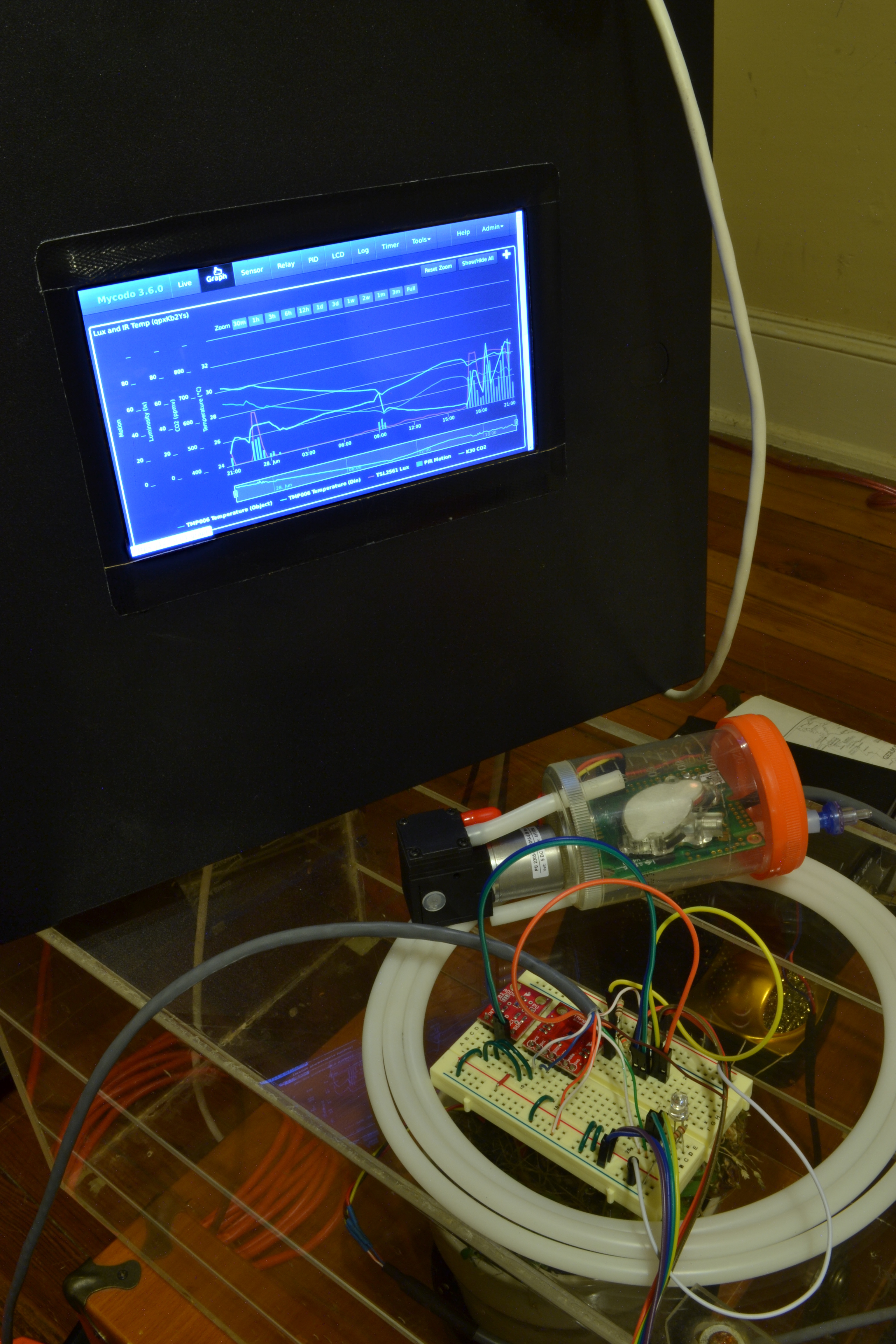
The system was shut down and ethernet cable removed. A carbon dioxide (CO2) sensor (K-30) was connected to the Tx/Rx lines, an analog to digital converter (MCP3424), a liminosity (TSL2561), and a non-contact temperature sensor (TMP007) was connected to the I2C lines, and a PIR motion sensor was connected to a GPIO with a resistor. A soil moisture probe was connected to a channel of the analog to digital converter.
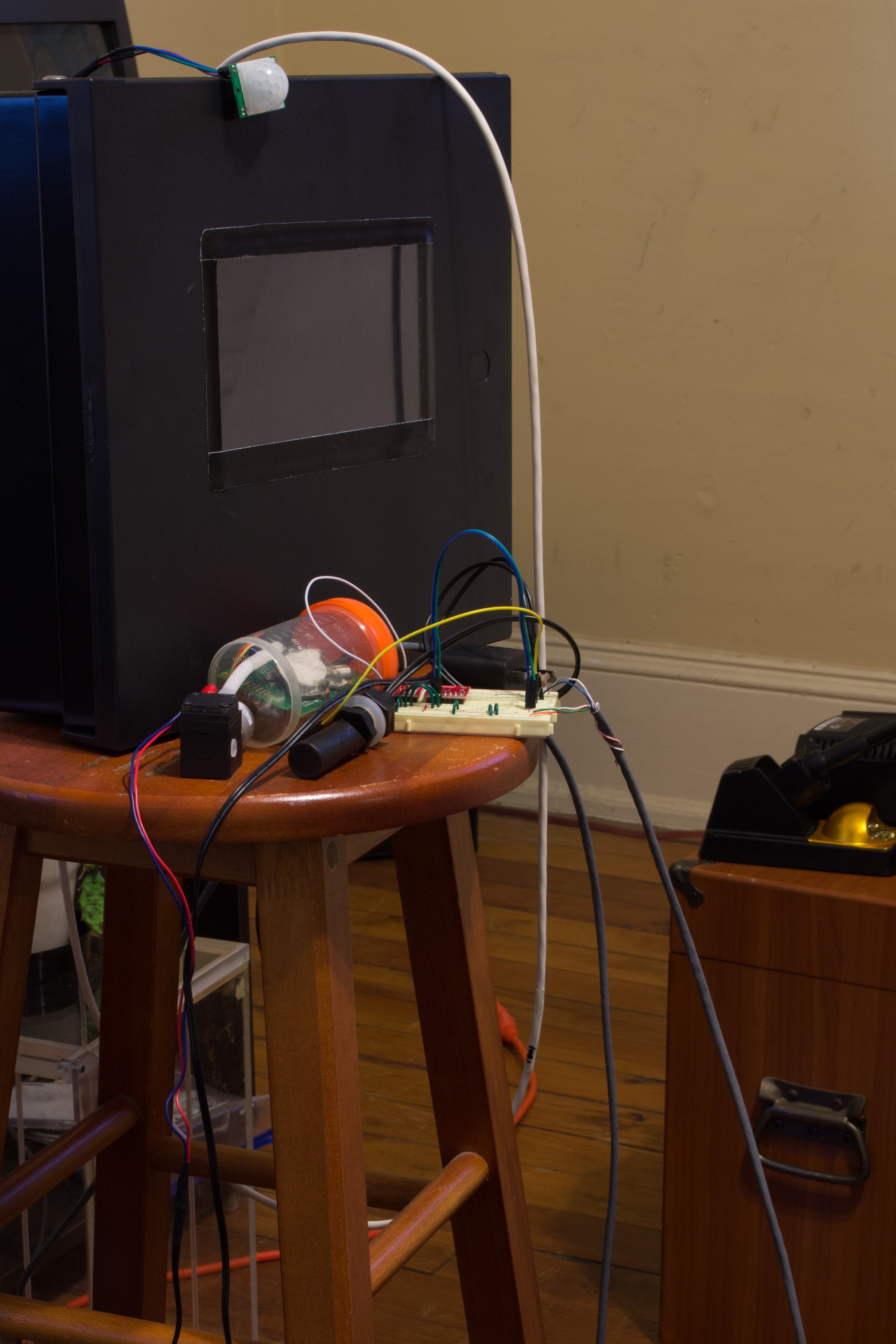
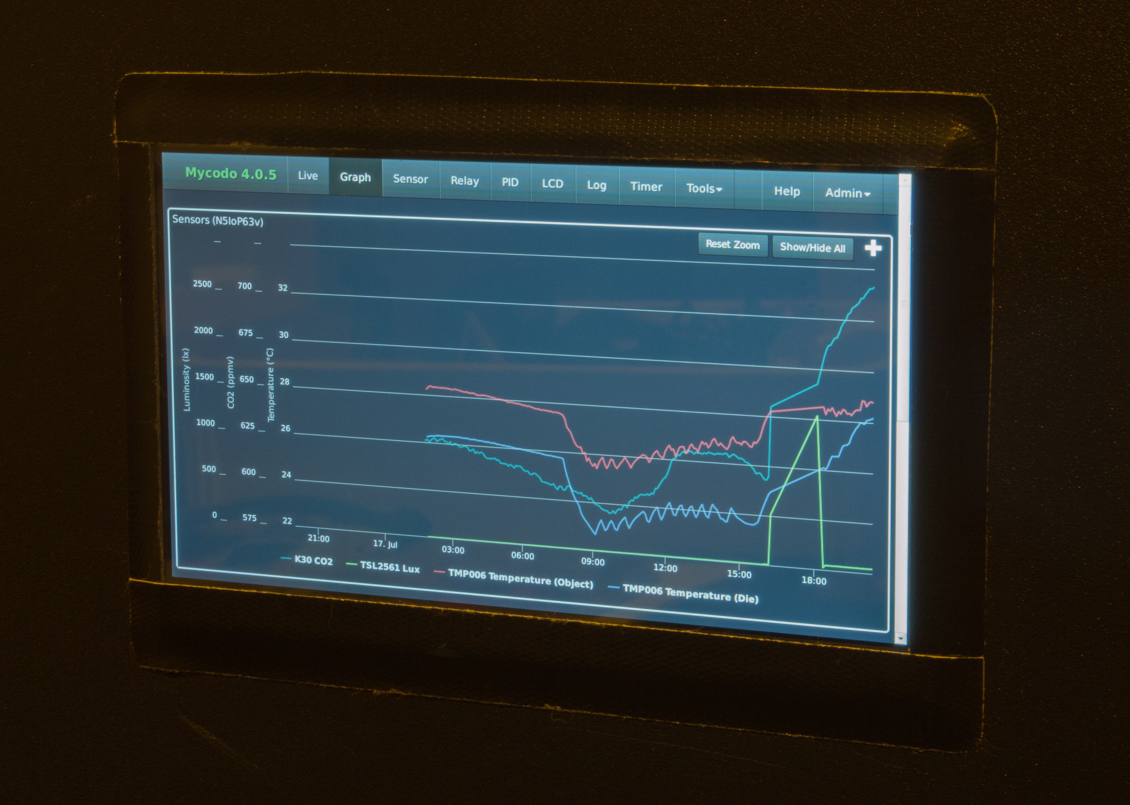
The RPi was powered and Mycodo was configured to use all the connected sensors. Here's the fruits of my labors for this session. Next session will see the addition of relays and we can begin controlling devices based on our sensor inputs
Note: The LCD is actually much better-looking than this photo depicts. I think the vastly-different color temperatures between the LCD and incandescent lighting was to blame, and I didn't care to try to correct it. More photos will come, but here's a nice end to the first actual build log for this particular system.
![]()
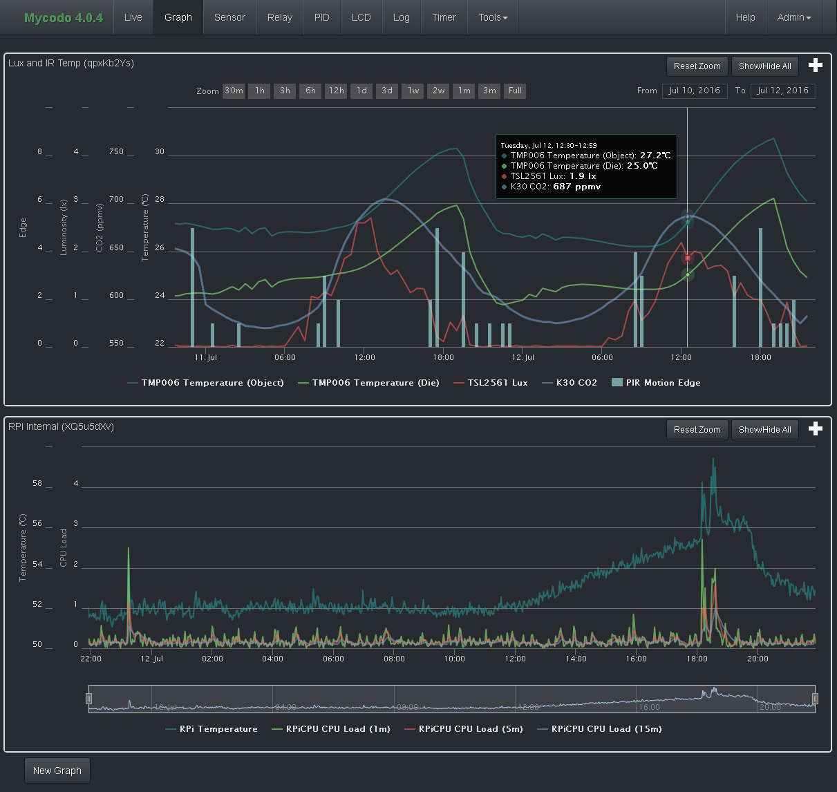
And below, a screenshot of the graph page of Mycodo, set up to display all the sensor data being logged on this system, on two graphs.
![]()
Mycodo - Environmental Regulation System
Bringing industrial automation and regulation to everyone.