Alain Mauer
-
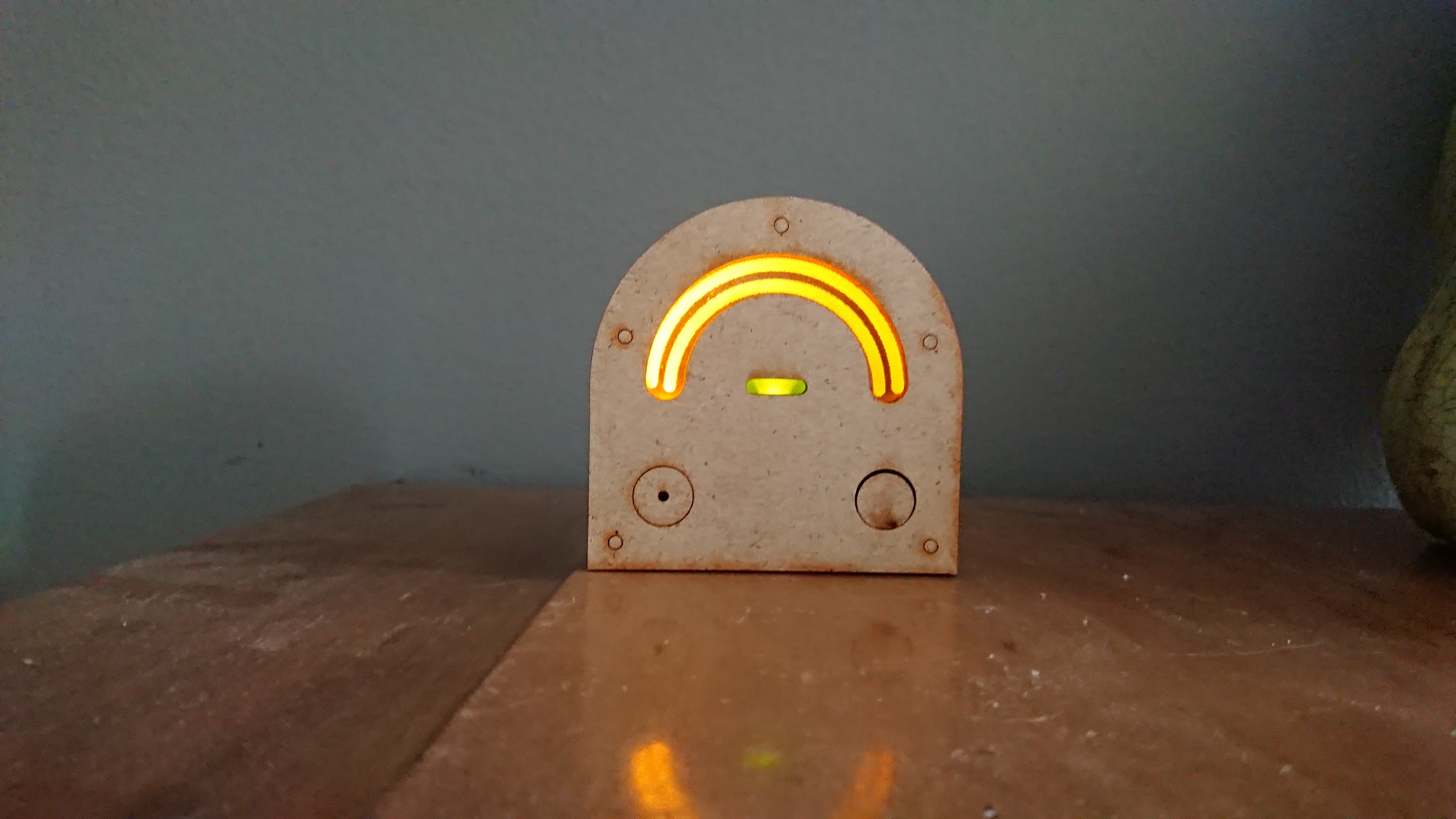
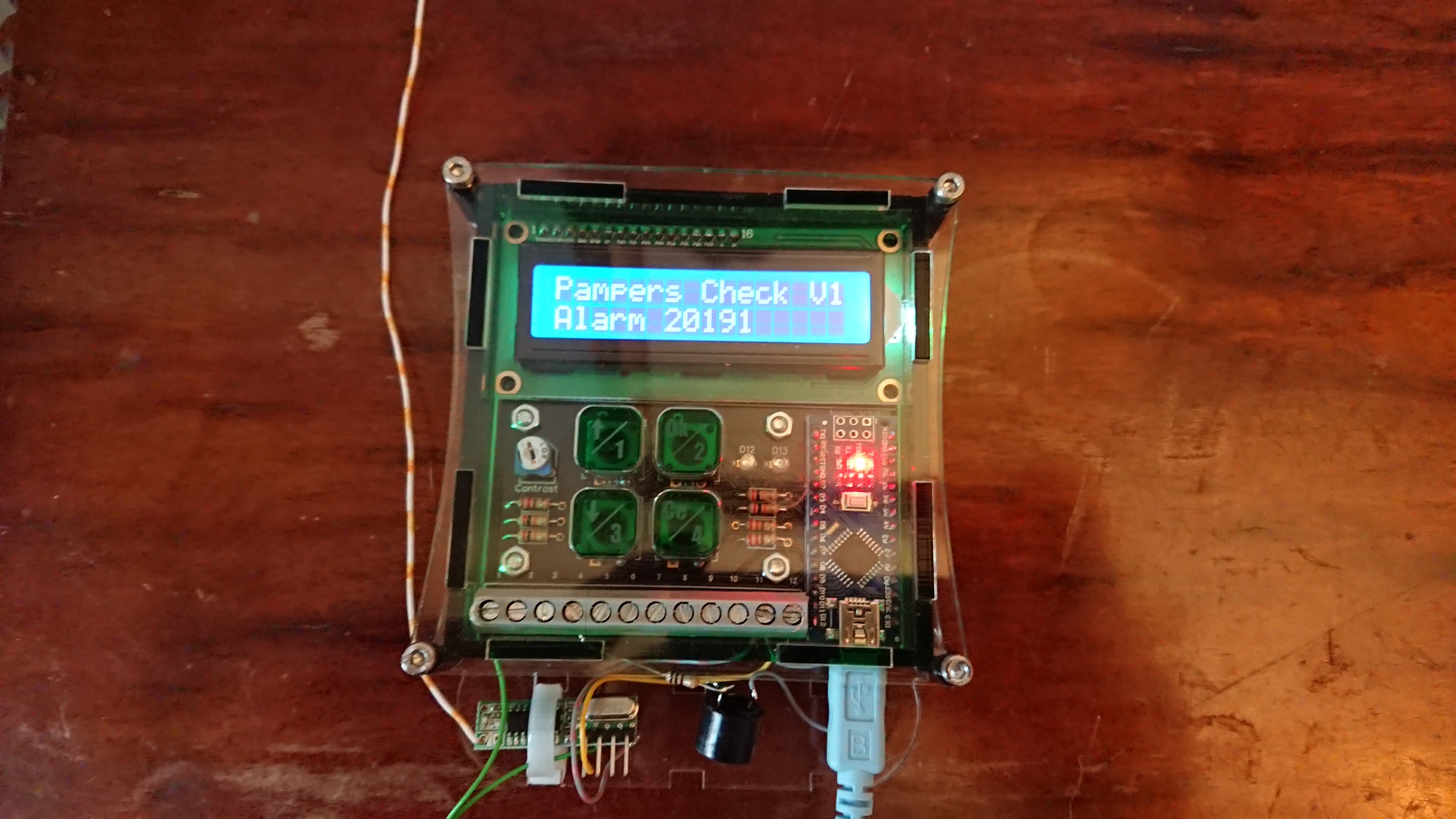
The USB Powered Receiver Is Ready
09/19/2019 at 17:27 • 0 commentsAnd here it is in action
When triggered, It beeps a few times and the LED's will show you, that there was an activation. You have to reset the led manually.
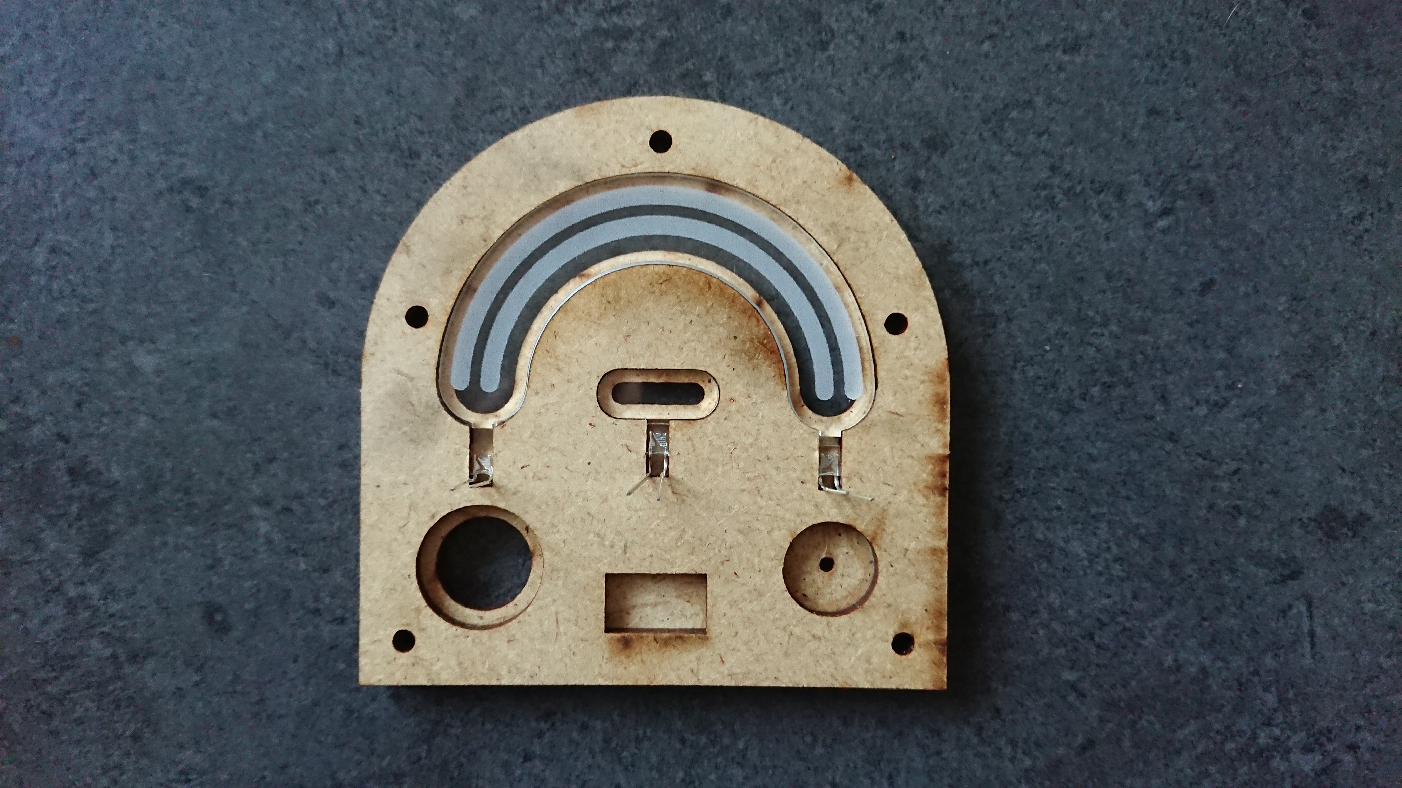
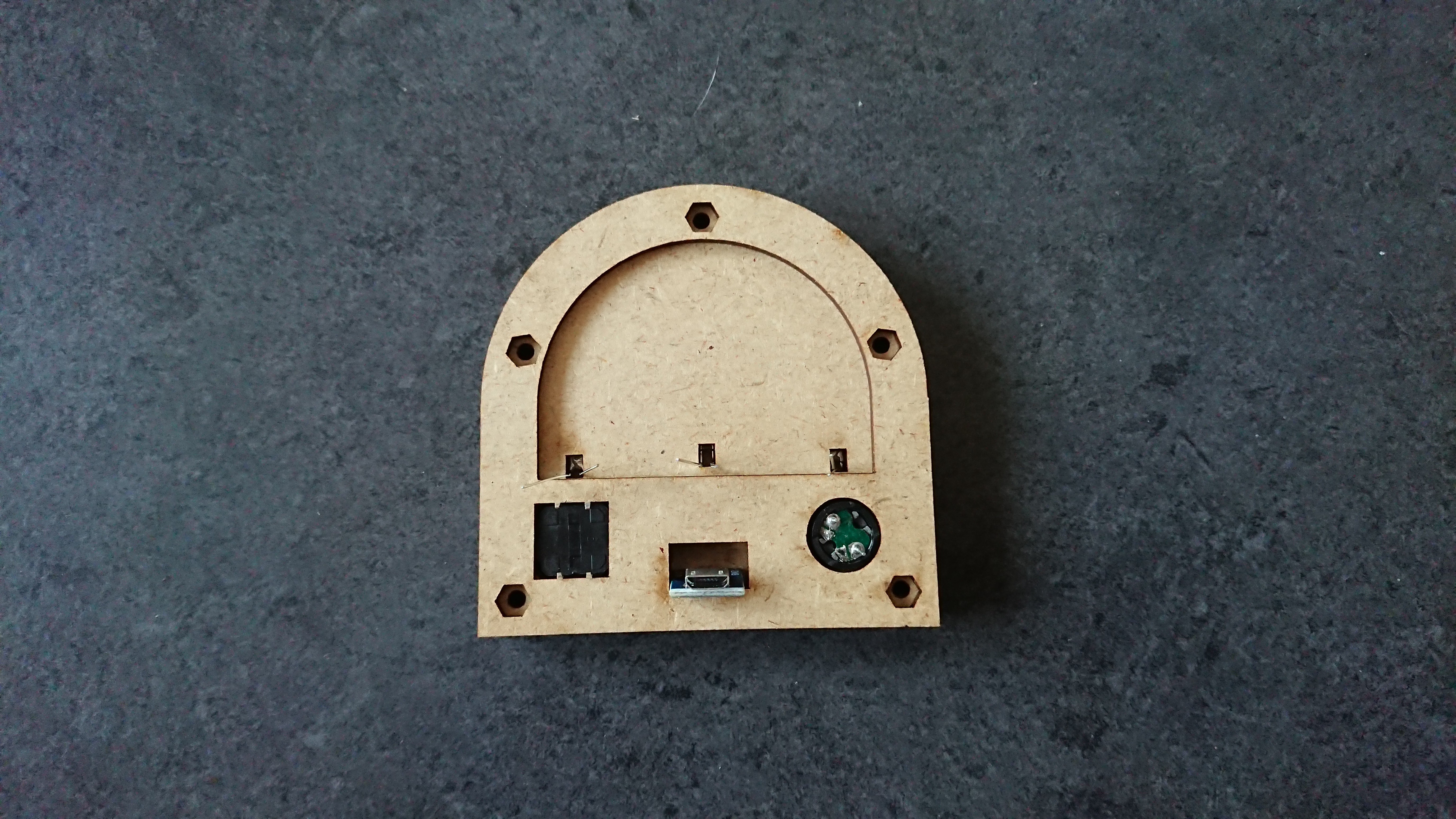
The quick build:
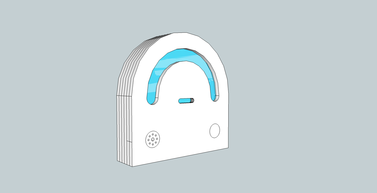
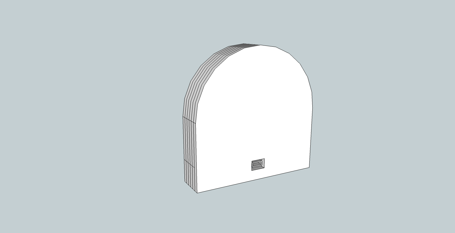
fist a 3D design in Sketchup 8

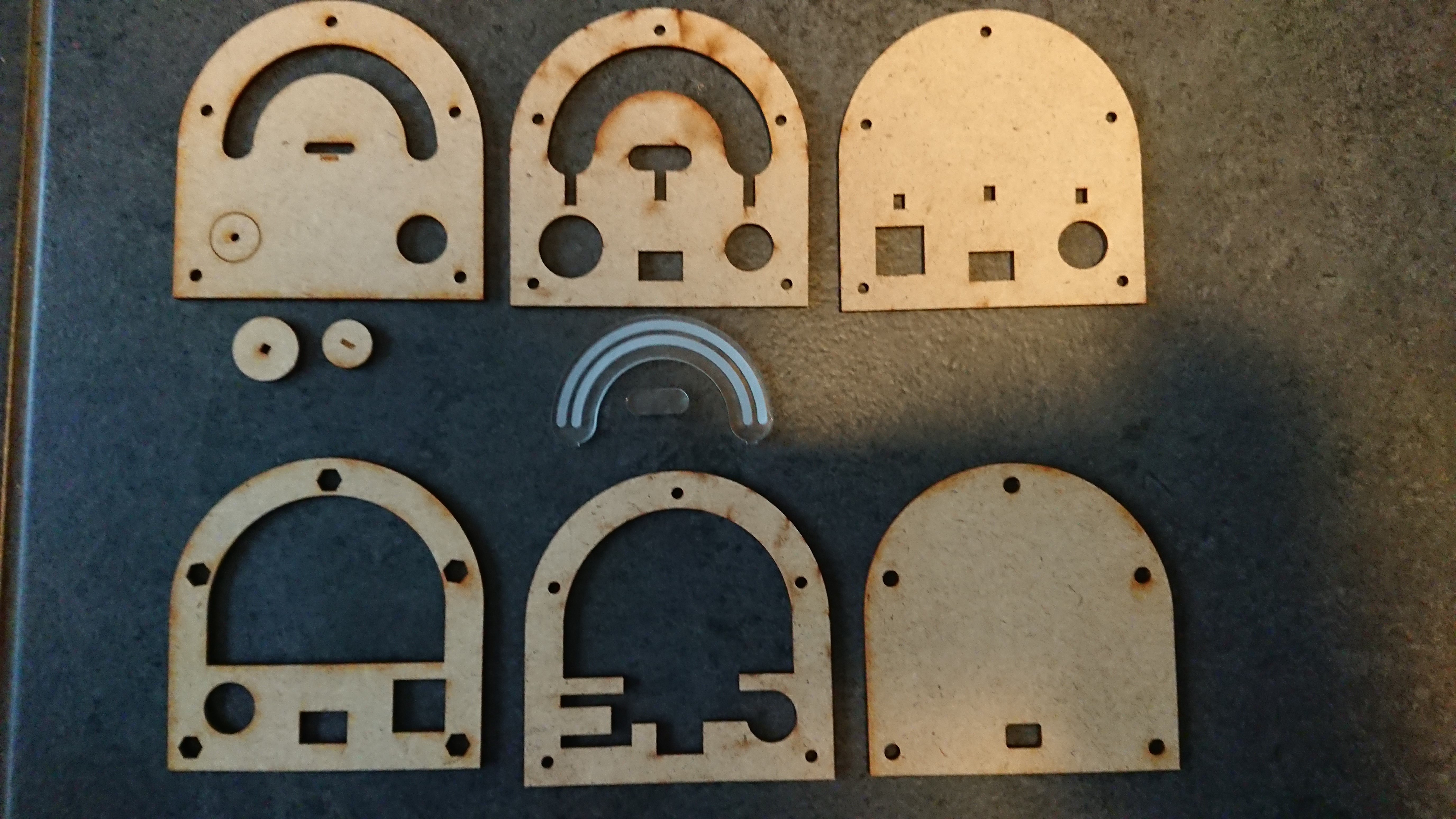
Lasercut parts
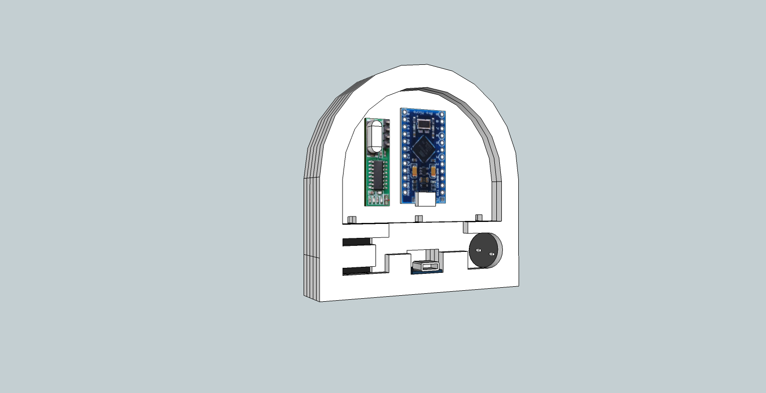
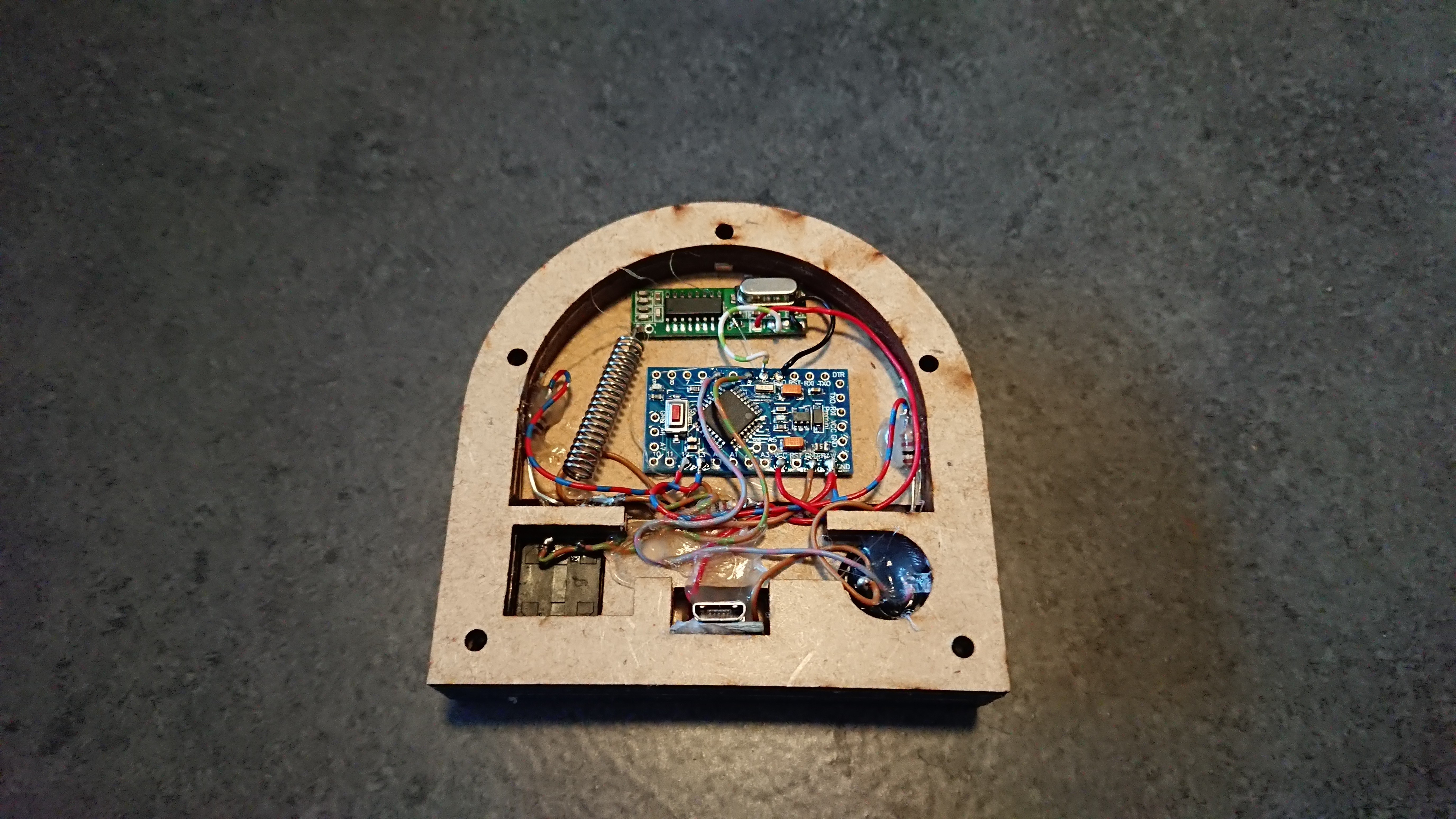
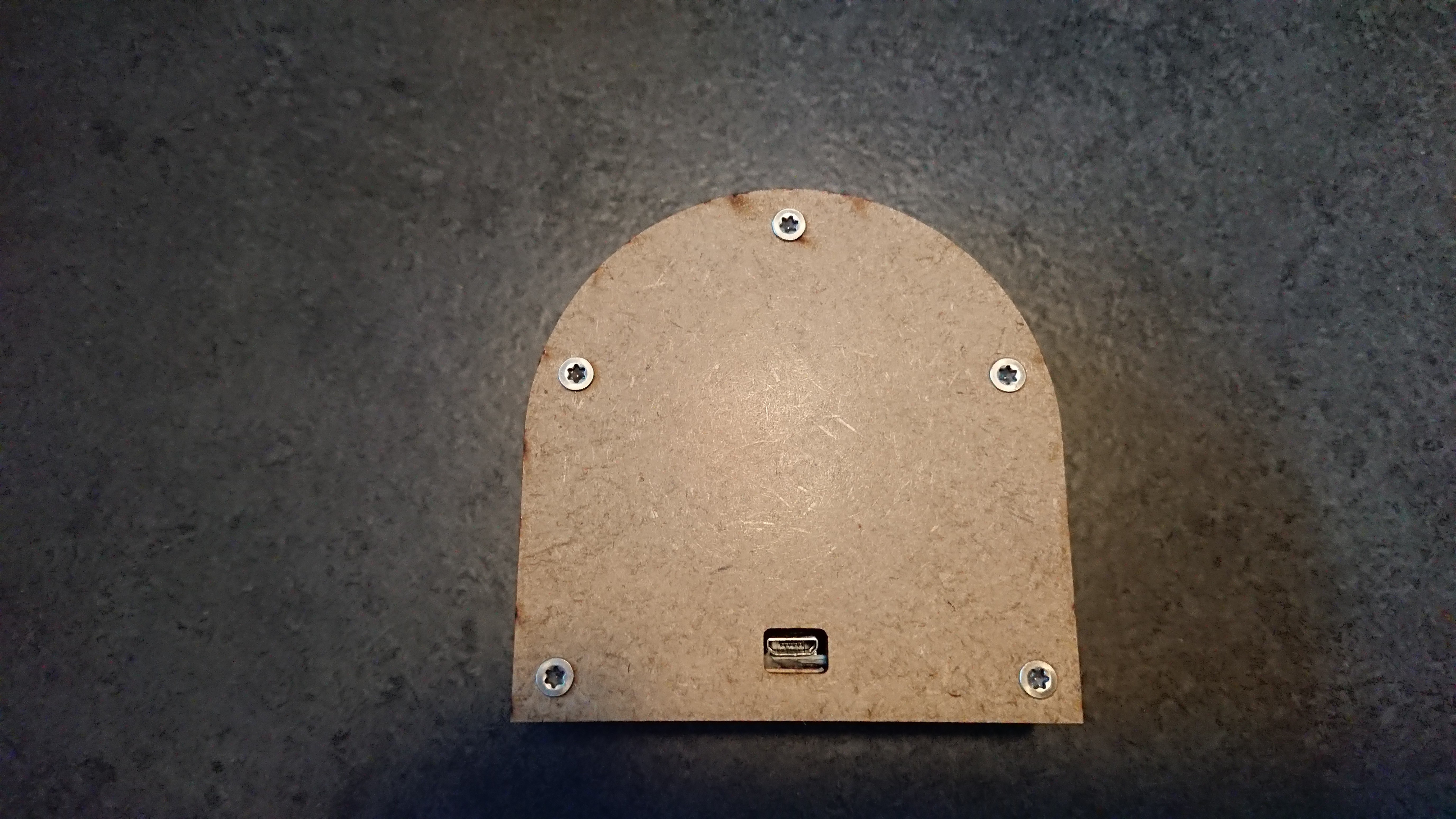
All together
Little update:
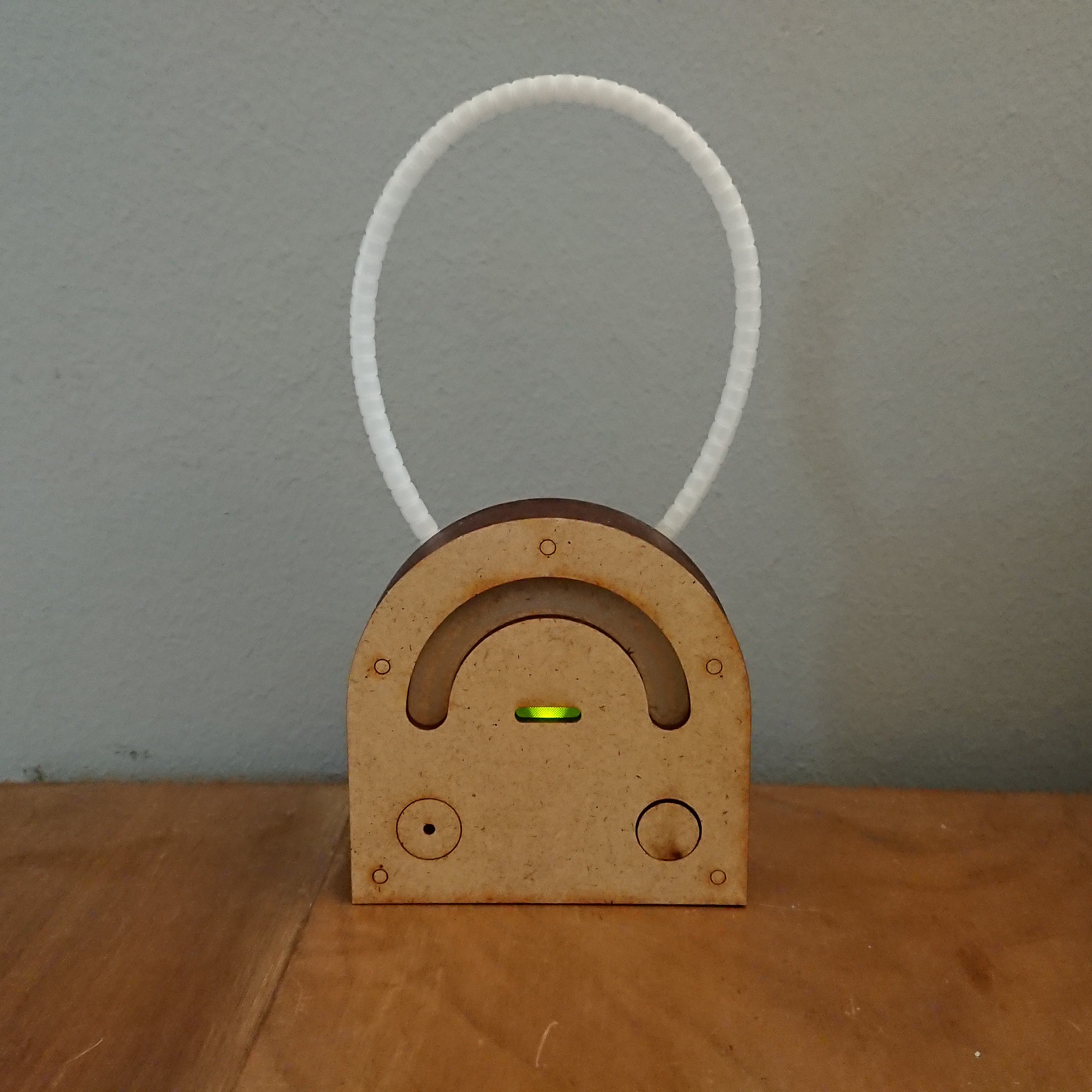
Had to add an external antenna to increase the range. Being a designer is really not my mojo :)
-
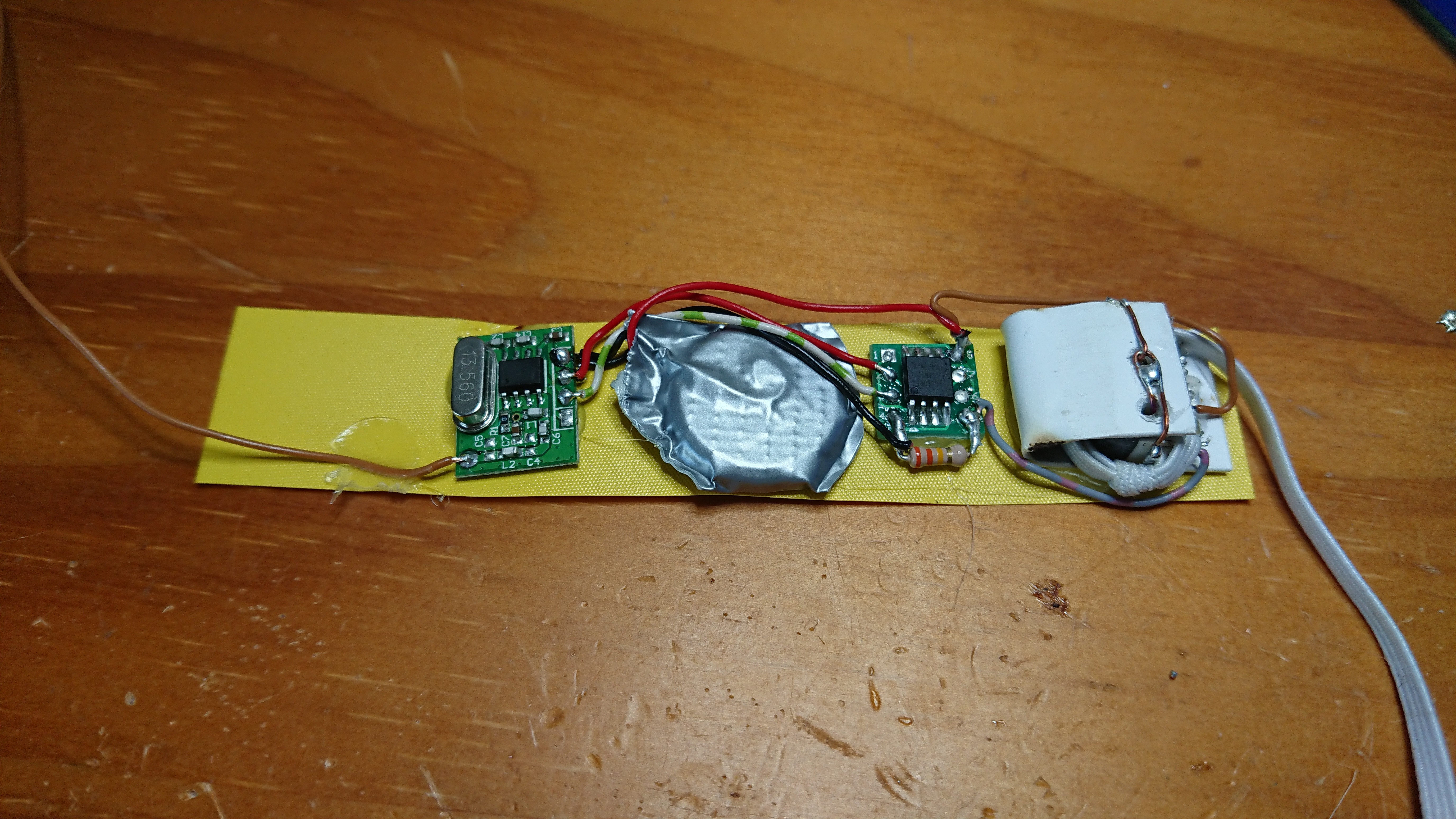
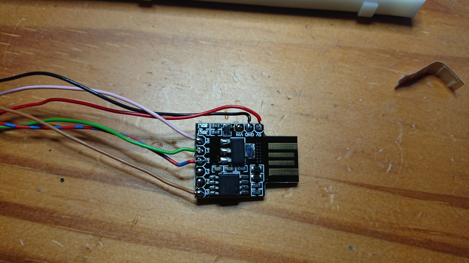
Building A Second Prototype
09/15/2019 at 17:55 • 0 commentsWorking on the second one. This time I use an attiniy85 and an SOP8 to Dip8 adapter.
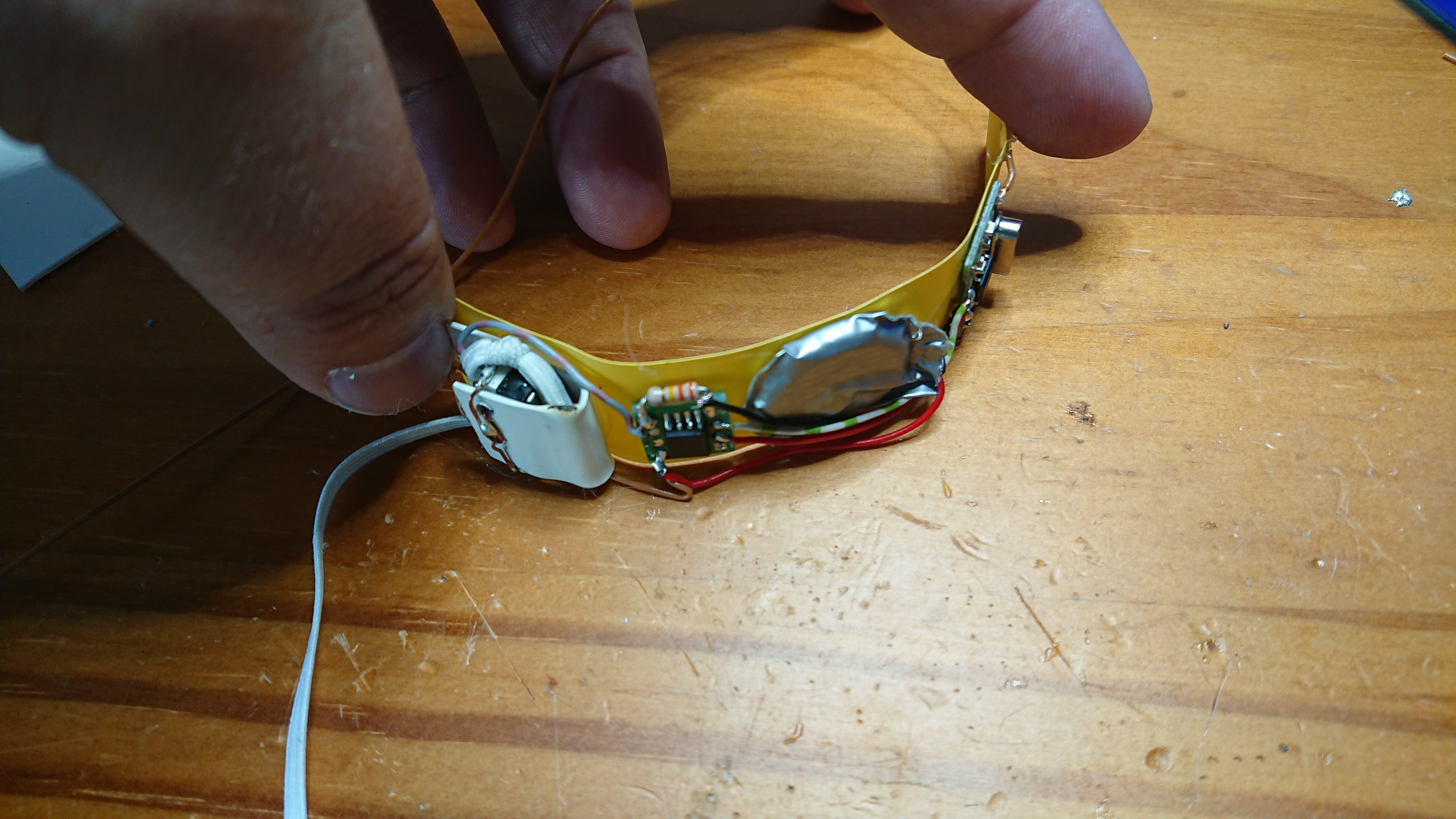
The whole thing is now a poor man's flexible PCB for wearables :)
It will be a removable version but I have to ameliorate my sewing skills.
-
Status Update After A Clean Room Week
09/11/2019 at 06:43 • 0 commentsAs mentioned in the title, yeah, it works.So what are the first Results:Each time the pants were removed, the system informed us.Two times, it did not work, but I saw it on the camera, so nothing happened. First, I thought, that there is a problem with the transmission, so I installed a second receiver near the room, but this was not the problem.
It's a mechanical problem. When he removes the pants, with the left hand at the back, the tension to activate the switch is too weak. It's not really a problem, because 10 times out of twelve it worked.
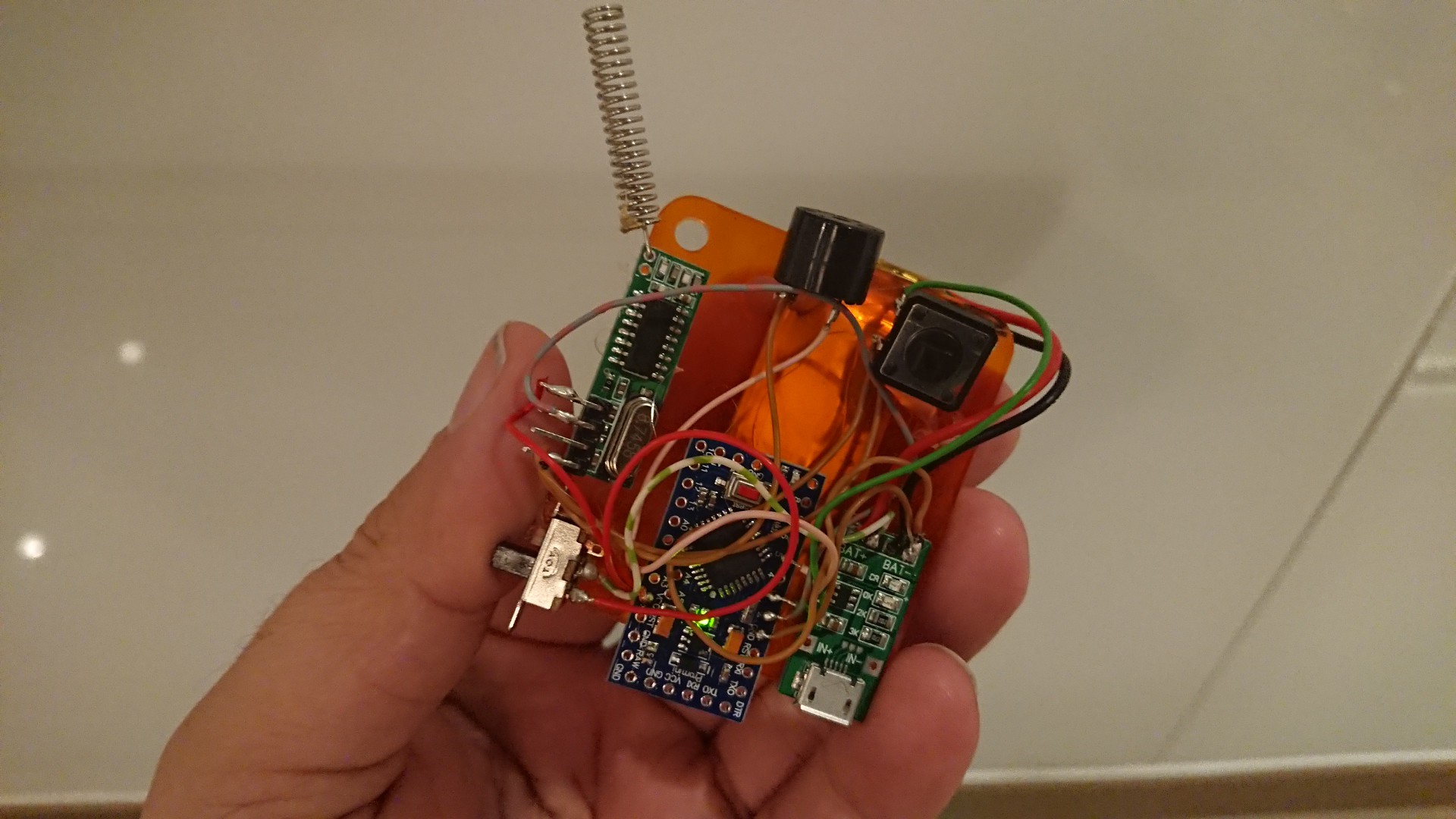
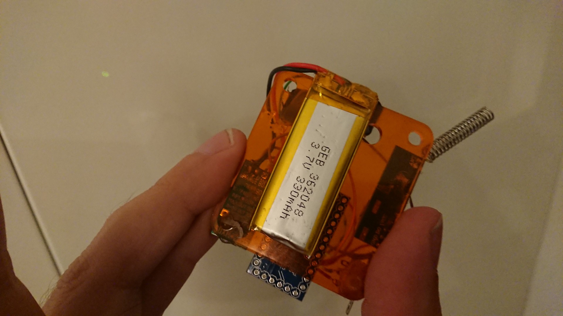
I've already started to build the portable receiver. It won't win a beauty contest, but it works.
Working now on the enclosure and a clean wiring. Will update the receiver part in the "BUILD INSTRUCTIONS" after that.
-
Successfully Tested Prototype
09/07/2019 at 10:27 • 0 commentsYeah it works.
This version is sewed to an old pants for test and and my son carried it, in the night. I got 3 alarms.Two in the evening and one this morning at eight o'clock. Each time I was there in time, to change his diaper or to put him on the toilet, to avoid a catastrophe.
Even if this works like it should, it's not a good idea to attached it this way to the pants. I would need to put one transmitter on each one, and they had to be water proved and washing machine resistant.
So I think, some kind of belt will be the solution. I will now transform a pair of pants with this system, so that it will help us for the next days, and I will concentrate on this belt stuff.
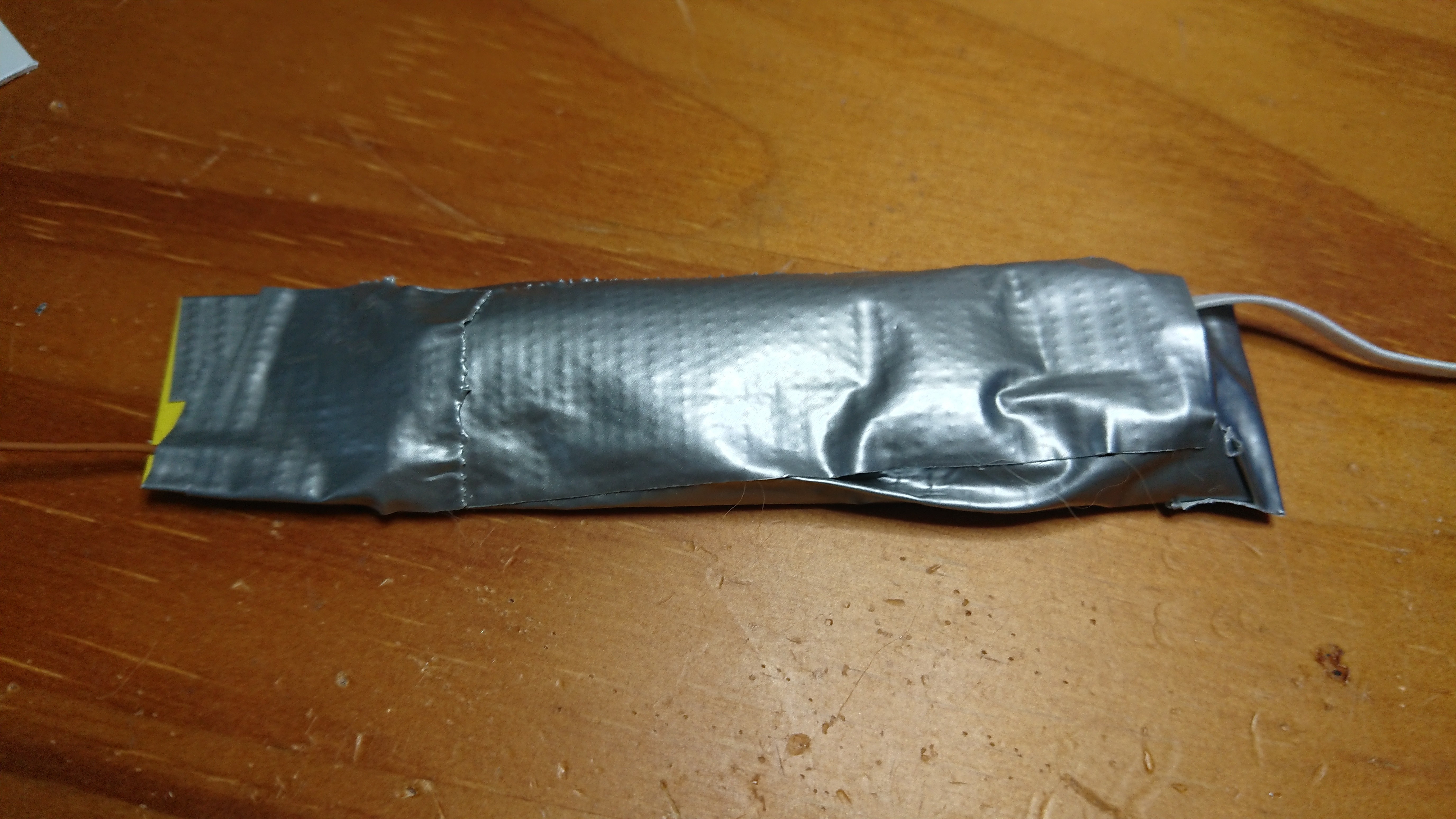
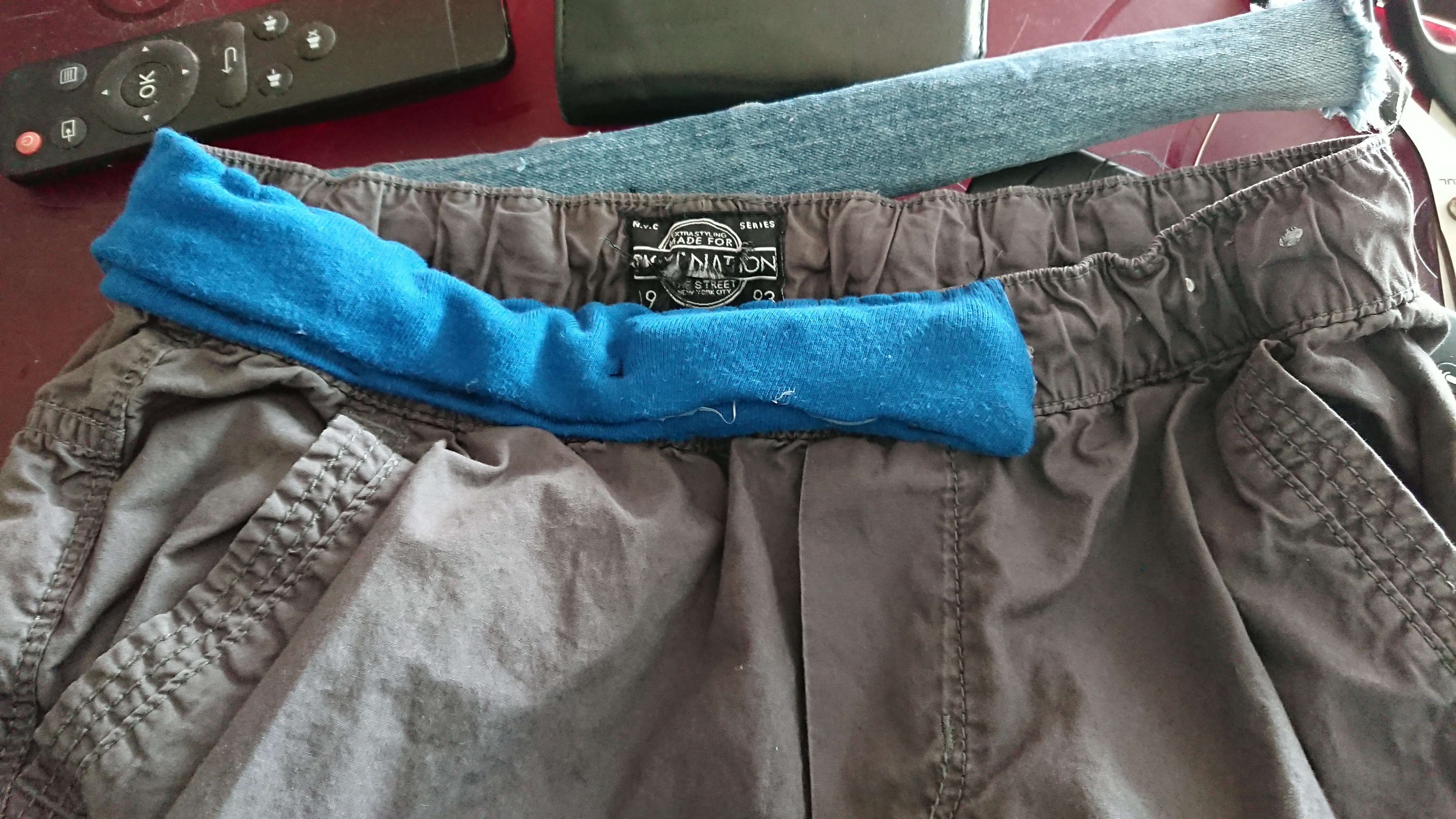
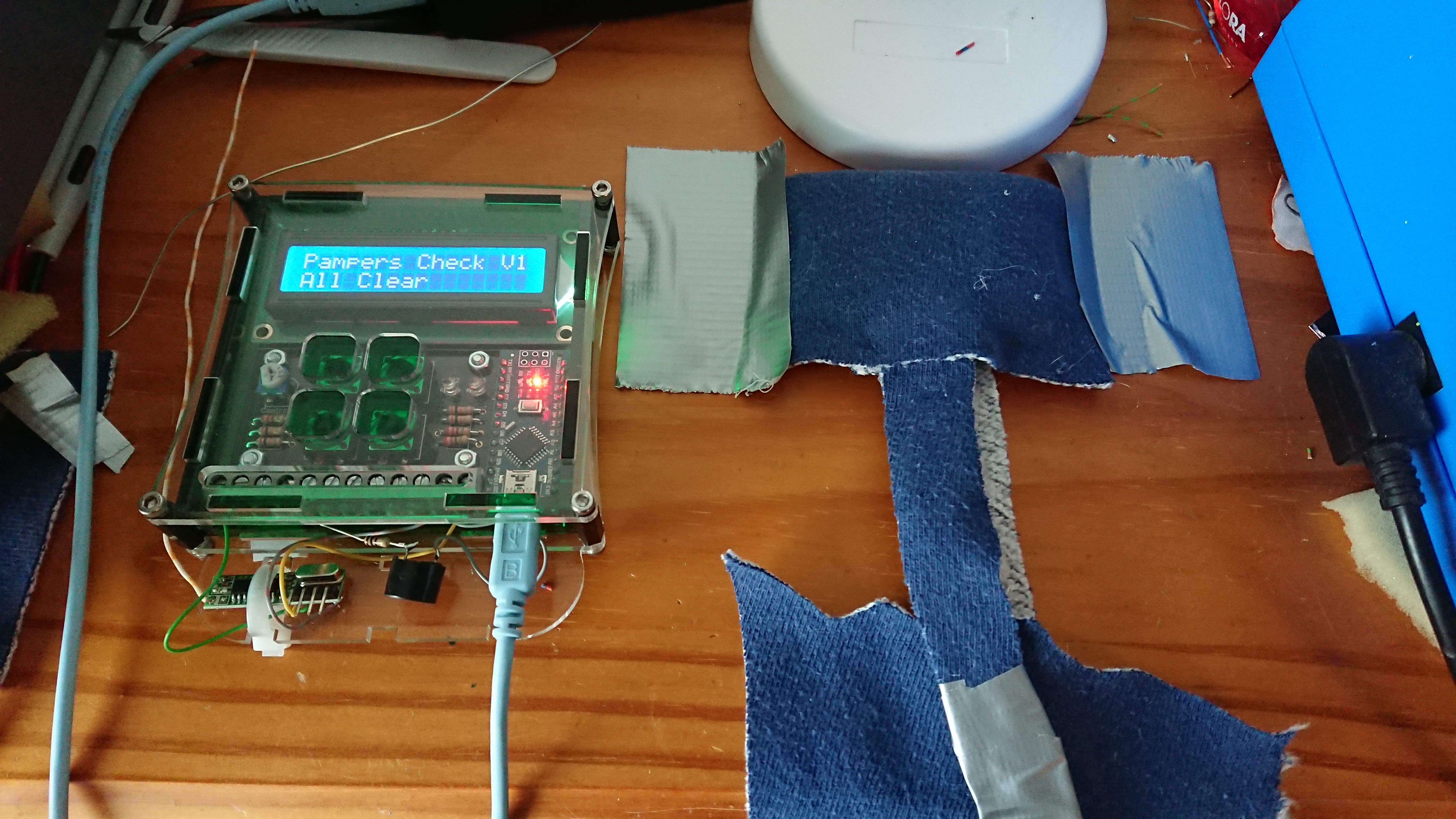
I sew a small tube out of fabric. First I used jeans from an old pants, but is not very elastic, so I switched to an old shirt.
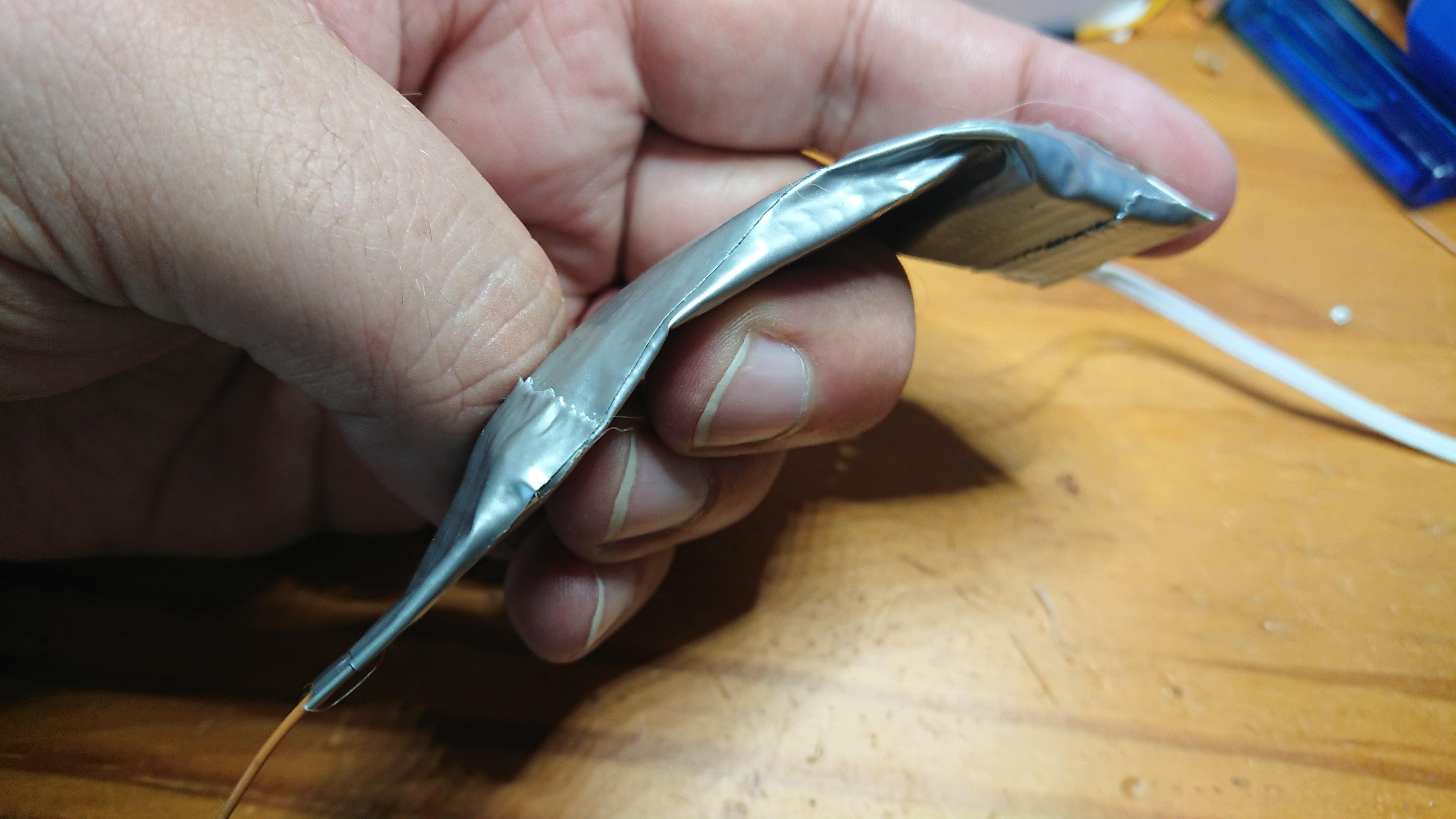
The electronic was hot glued on a small piece of foam an with the help of duct tape isolated.
the elastic band was fixed on the other side. The tension was just not big enough to handle the switch.
Then the tube was sewed to the pants. same here, the tension did just not activate the switch.
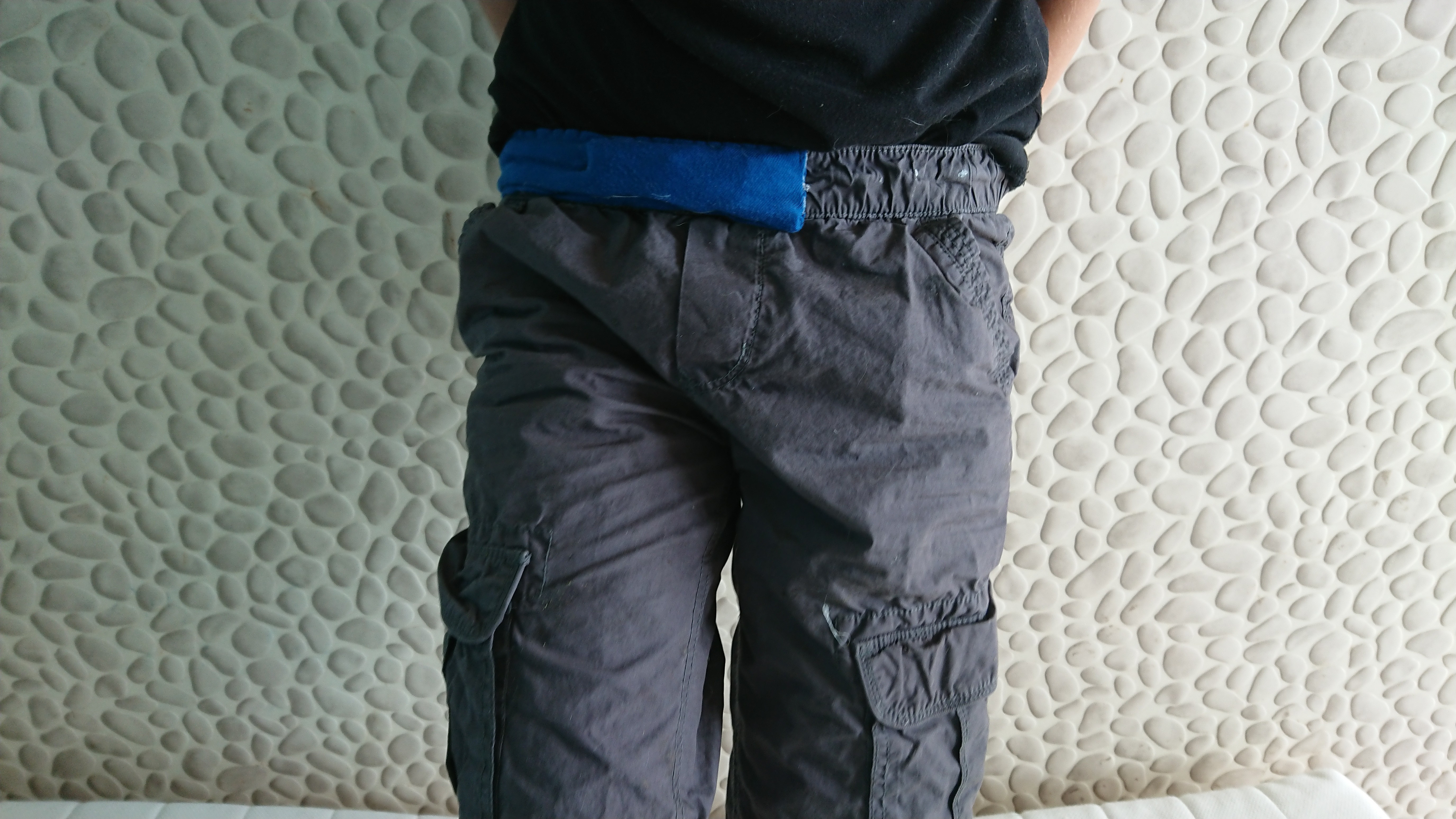
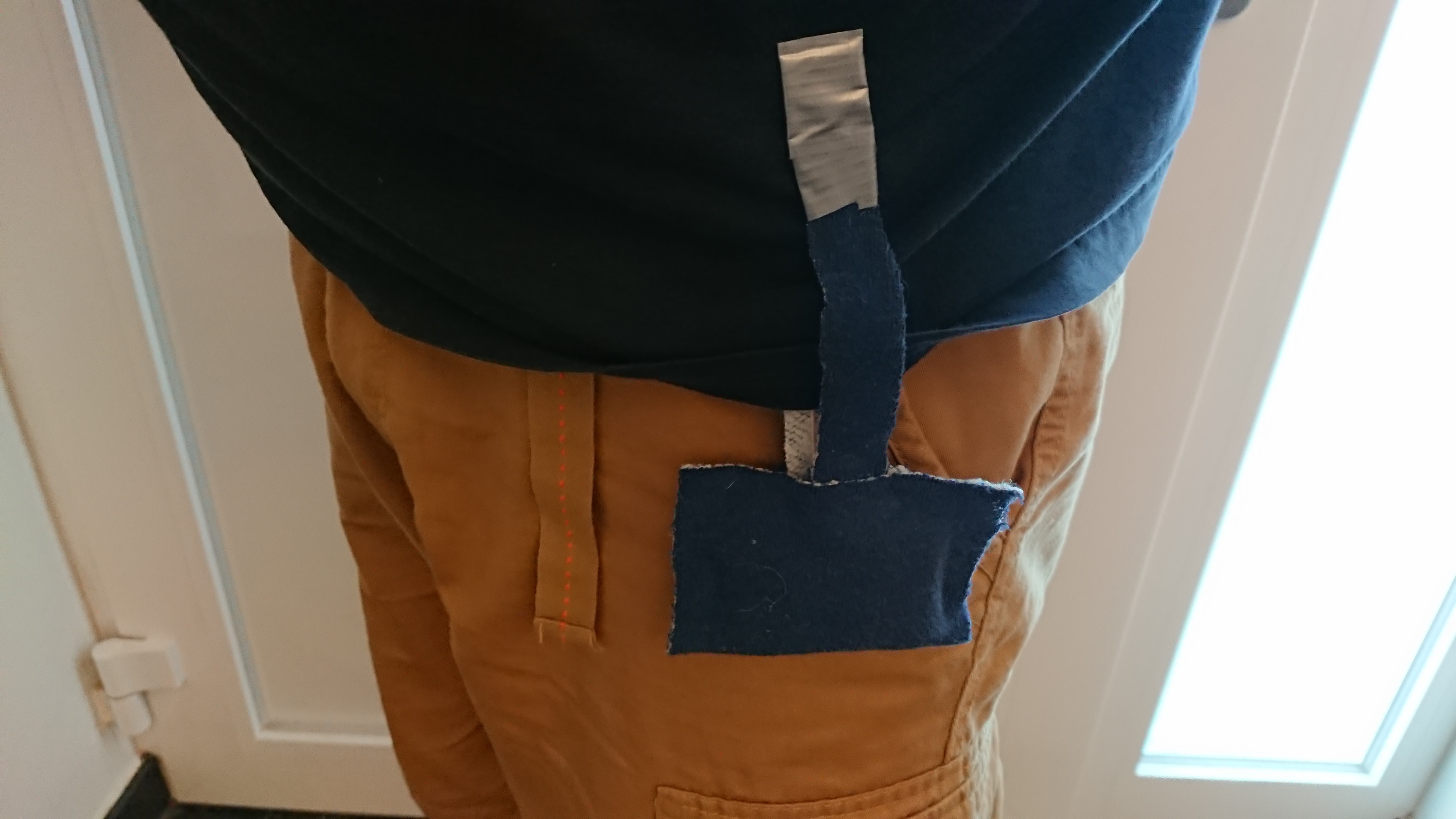
And here the whole thing on the test subject :)
-
Back To The Pull Switch
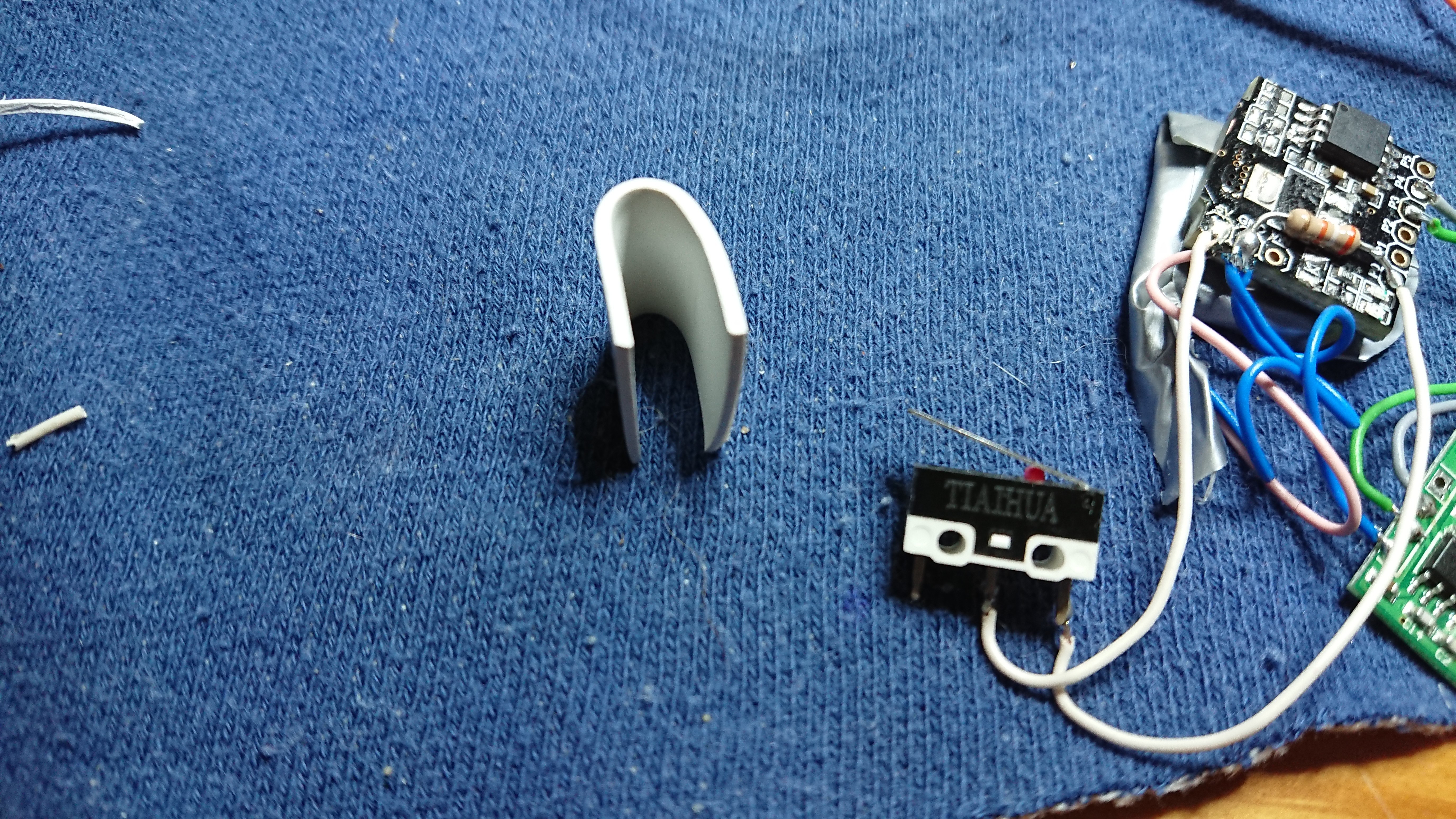
09/07/2019 at 09:51 • 0 commentsMy first Idea was, to use a micro switch and I came back to this Idea.
I just changed the design, to make it simpler to use and my son will not detect that we there is something manipulated by us. I analysed, what happens, when he removes his pants, and I saw on the surveillance video, when he removes his clothes or when he goes to the toilet, that he has to pull sideways on the pants to remove them, so I decided to try something with a pull switch.
Seems to work.
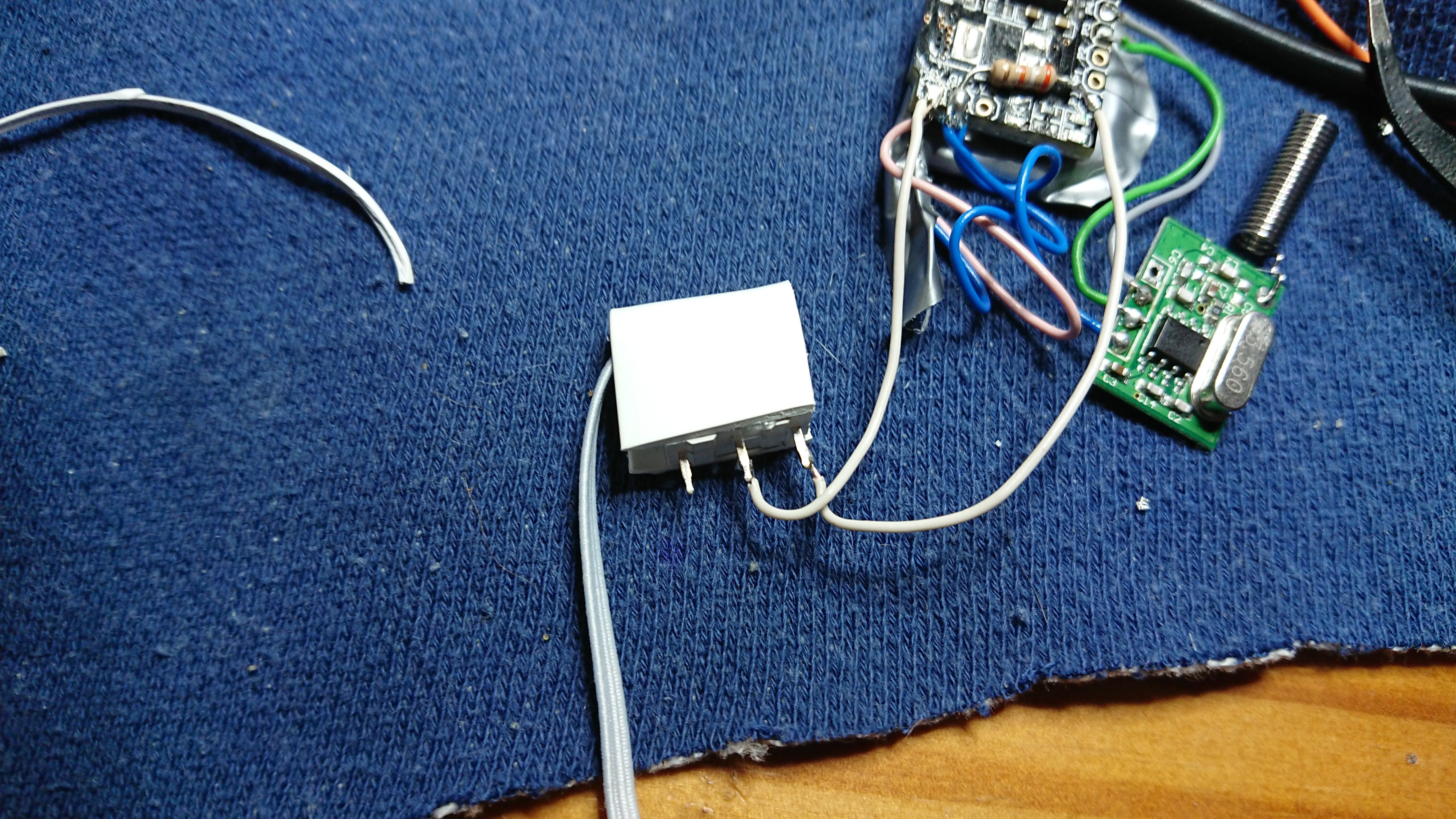
I use a micro switch, and put a small protection over it, so that the cord will not be blocked in the foam and fabric. A small piece of PVC bend with heat will do the job.
-
Transmitter Prototype II
09/07/2019 at 09:30 • 0 commentsOk next try.
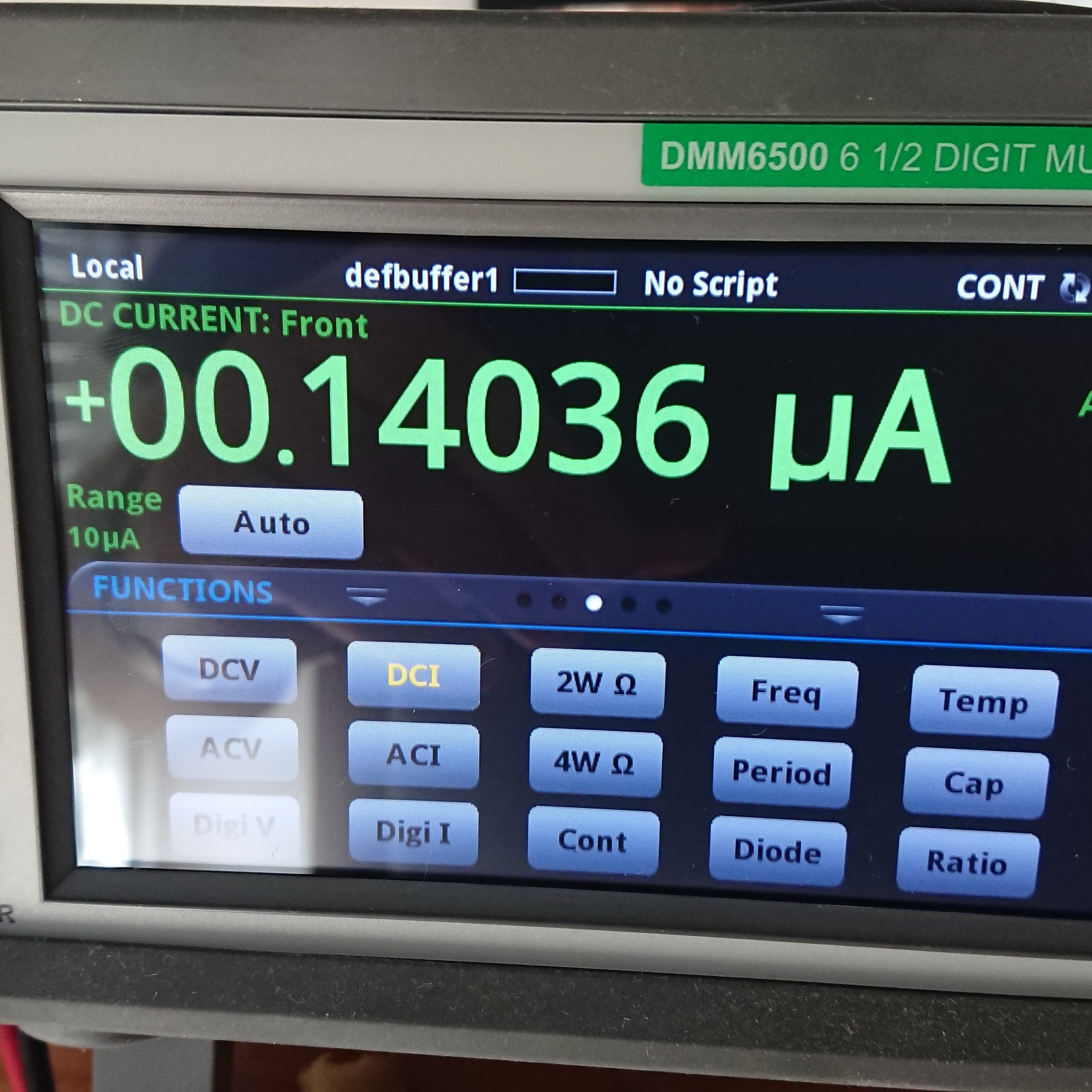
I modified the software and the transmitter works now on interrupt. On interrupt it transmits two times the code, and goes to sleep, until the next interrupt. The circuit takes in standby 0.14uA. I can live with that and the CR2031 should last for 10 years ins standby. Transmitting takes about 0,7mA for a very short period
-
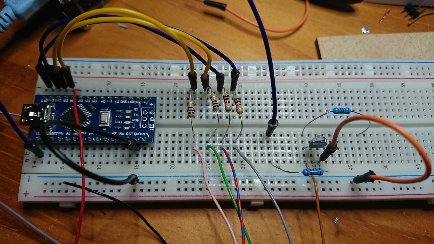
The Receiver
09/07/2019 at 09:21 • 0 commentsThe receiver was very easy to build. I used one of my Arduino QP https://hackaday.io/project/159468-arduino-nano-qp
and I connected a simple 433Mhz Rf receiver module to it and a a piezotransductor
A few lines of code, et voila. -
First Prototype....Fail
09/07/2019 at 09:16 • 0 commentsThe attiny85 runs now at 1Mhz. I removed all the parts of the digistump, so I could use it as simple attiny.e
The pillowpart should be attached to the pants, and the 2 neodyms with the Shirt in between. The basic idea behind this was, that when the shirt or the pants are removed, the 2 contacts jump together and the microprocessor transmits a code. then it goes to sleep.
The Idea was not bad, but I forgot en unknown variable in the scenario: My son :)
He saw, that I attached something to his shirt and immidatly he pulled on the two straps, so that the system was disarmed.
Now I know, that was not the best plan. So let me sleep a night over it. -
Relaunching the project
09/01/2019 at 12:06 • 0 commentsWe still have the problem and now it's really time for this project. Even if it sounds not complicated, I had first to learn a little bit more about Arduino programming and to understand the fuse bits and boot-loader stuff.
The Digitump Attiny has the fusebit set to lock the pin 5. This pin is needed for ISP programming. So I used this Instructable "Fuse Reset Attiny" to reset the fusebits with 12V.
After the reset , I could finally upload a 1Mhz Boolloader and I make the Digistump run on 3V
Here my quick and dirty fuse bit reset'er.
UD-Alert
This undress alert is for my thirteen-year-old son suffering from autism