 Joel Villa Farias
-
1Step 1
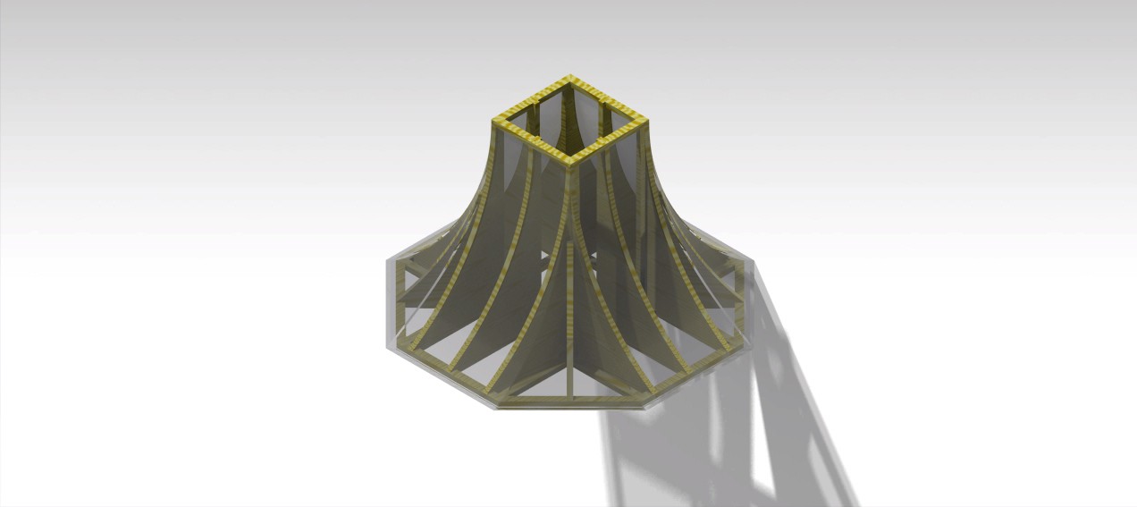
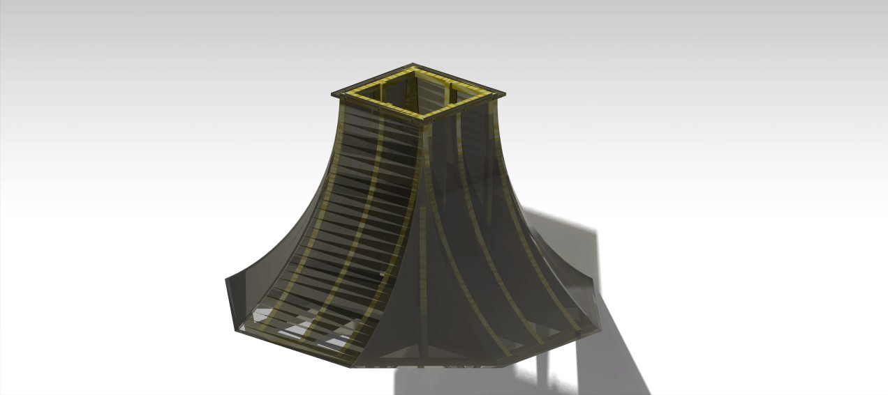
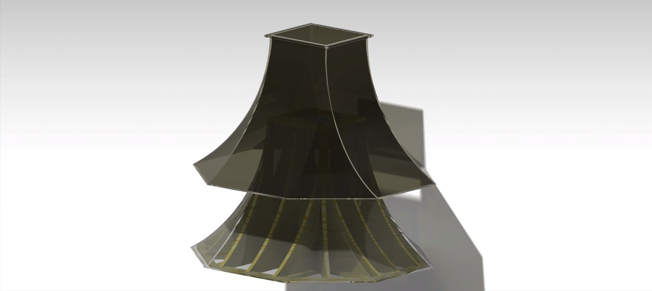
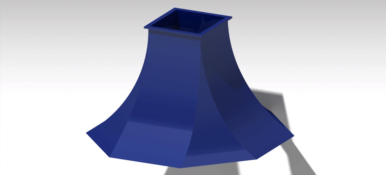
HOW TO BUILD THE STRUCTURE PATTERN FOR OUR WIND TUNNEL
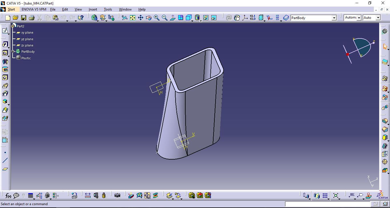
- The structure we have designed with the design program Catia from surfaces that we created earlier.
- The manufacture we have made with panels and moldings with wood of pine.
- The assembly did it with a nail gun and glue.
- Surfaces make up plates of methacrylate 2mm thick.
-
2Step 2
FABRICATION OF THE WIND TUNNEL FIBERGLASS BODY
1. Wax the mold with wax for ships covering the whole surface, It is important to do that for the time of unmold do it with ease.
![]()
2. Cover the surface of the mold with sheets of glass fiber such and as explained in the following video. Repeat the operation at least to have 3 layers.
3. In the ends of the bodies that are joined to another body of the wind tunnel place angles of aluminum between layers of glass fiber..
4. Let it dry completely the time that recommended by the manufacturer.
![]()
5. Unmold the body of glass fiber of the mold taking care if any item has been stuck to the mold.
![]()
6. Sand the surface . The surface, both interior and exterior it should be as uniform as possible for the later painted.
7. Paint the entire inner and outer surface of the different bodies at least two layers.
8. For a better finish polishing the different surfaces.
![]()
For all the previous operations is very advisable to take the precautions that indicates the manufacturer of the different products it is used.
-
3Step 3
HOW TO BUILD THE TESTING CHAMBER AND THE FORCES BALANCE
- The angles of aluminum are of 25x25 mm section
- The connections of the angles and the methacrylate have been done by drilling and by riveting, except the plate of methacrylate side removable that is bolted to the same as the set of the balance with the camera.
-
4Step 4
HOW TO BUIL THE PANEL RECTIFIER OF FLOW OF CARDBOARD
In our case we bought the panel of cardboard to a manufacturer of cardboard furniture. The panel had some measures of 1400x1400 mm with a thickness of 20 mm.
To create and adapt the panel of cardboard to our tunnel we follow these steps:
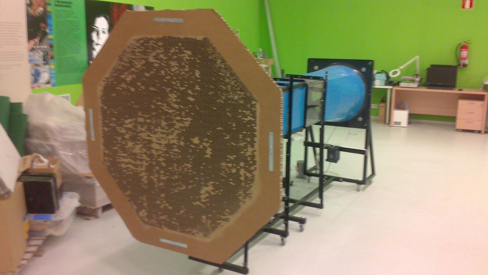
- Cut of hexagonal shape the panel leaving an outer frame of 200 mm with respect to the measures of the cone of acceleration.
- Cut on both sides of the panel the hexagon with measures in the cone of acceleration so shallow, seeking to cut only the cardboard outside.
- Remove the cardboard that we cut on both sides so that it is in the center of the panel uncovered the panel honeycomb.
- In our case we sand the thin cardboard plate because it was not detached well.
- Show the cardboard with the cone of acceleration and mark the position of the items in the vertical sides and horizontal of the cone of acceleration.
- Pierce the cardboard and the cone of acceleration.
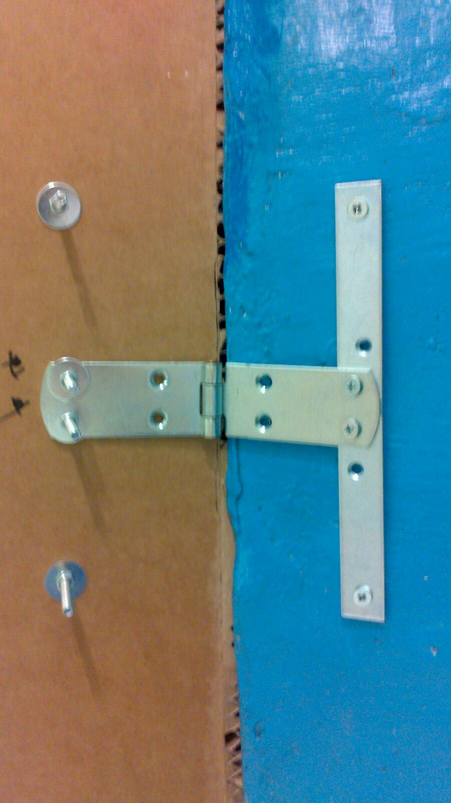
- Assemble items as they appear in the following photographs.
![]()
![]()
![]()
-
5Step 5
HOW TO BUILD OUR MACHINE OF SMOKE
For the deposit we have used a canteen with two types of openings one with major diameter than the normal one, what us it will allow to be able to introduce in its interior the water bomb.
We start by piercing two orifices, one in the base so that they happen the cables of the bomb towards the exterior, and other in the top part where there was happening the pipe that was communicating it with the heater.
We introduce the bomb inside the deposit and connect it with the pipe. The pipe and the cables will cross the walls of the deposit. We seal with silicone the holes that we have realized in the canteen.
For the heater we have used a thermos flask to maintain liquid the temperature to which we it introduce the biggest possible time.
We start by piercing thebase of the heater to introduce the boiler and the side street to introduce the liquid originated from the deposit. When the boiler can interfere for the base of the heater we place it in its interior and we seal the heater. We will repeat the operation that we did with the pipe of the deposit. Pierce the lid of the thermos flask and to place the end of the gun of silicone followed by a pipe that will go to the tunnel.
-
6Step 6
PREPARING THE FAN FOR ITS OPETATION
To prepare the fan for its functioning we must realize a series of tasks:
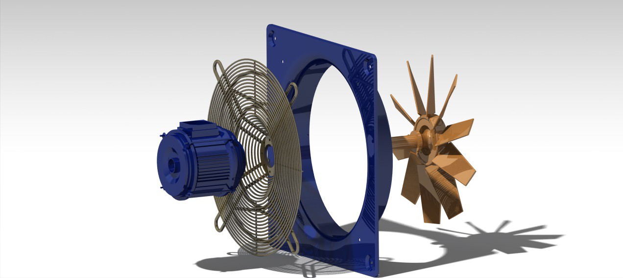
- With the fan separated from the rest of the tunnel, we disassemble the set of helices and it we mount on the contrary of as it comes from factory.
![]()
- Mount the fan with the rest of the tunnel.
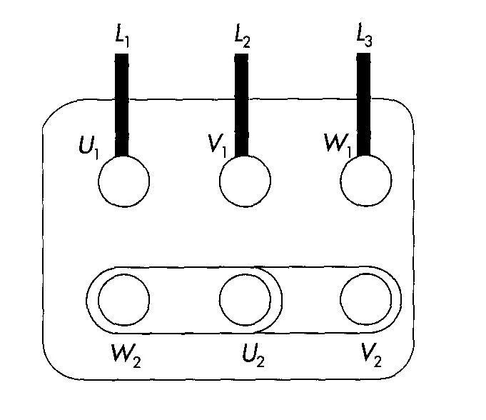
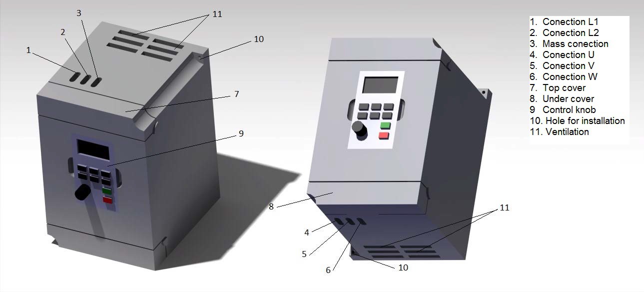
- The engine of the fan in this case its mounted with the configuration star electricity from factory. We have an exit of 4 cables, 3 of phase and one of mass. Connect the phases of the engine, represented in the following scheme, to its correspondents earnings U, V and W of the frequency variador. Connect the mass at the entry of mass of the variator of frequency.
![]()
![]()
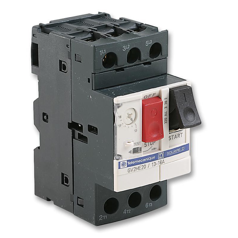
- Connect with a cable the inputs L1, L2 and Mass of the variator of frequency with the same exits of the breaker.
![]()
- Connect the inputs of the breaker with a plug of 220 V with capture to ground to be able to use it with the domestic electrical connection.
- Connect the circuit to the electric domestic network.
- Program the frequency variator so that he invests the sense of draft of the engine.
- Program the frequency variator to establish a starting and a progressive stop of the engine. This will avoid possible electrical and technical problems.
- Program a few low and top limits of frequency of the engine.
Now we will be able to change the frequency of the engine and therefore the speed of the air that will circulate inside the essays camera.
-
7Step 7
HOW TO PRINT THE SMOKE MACHINE DUCTS
Once we have designed the pieces of the conduits of the machine of smoke keep them with the format IGS to be able to import it to the program of impression of the printer 3D.
![]()
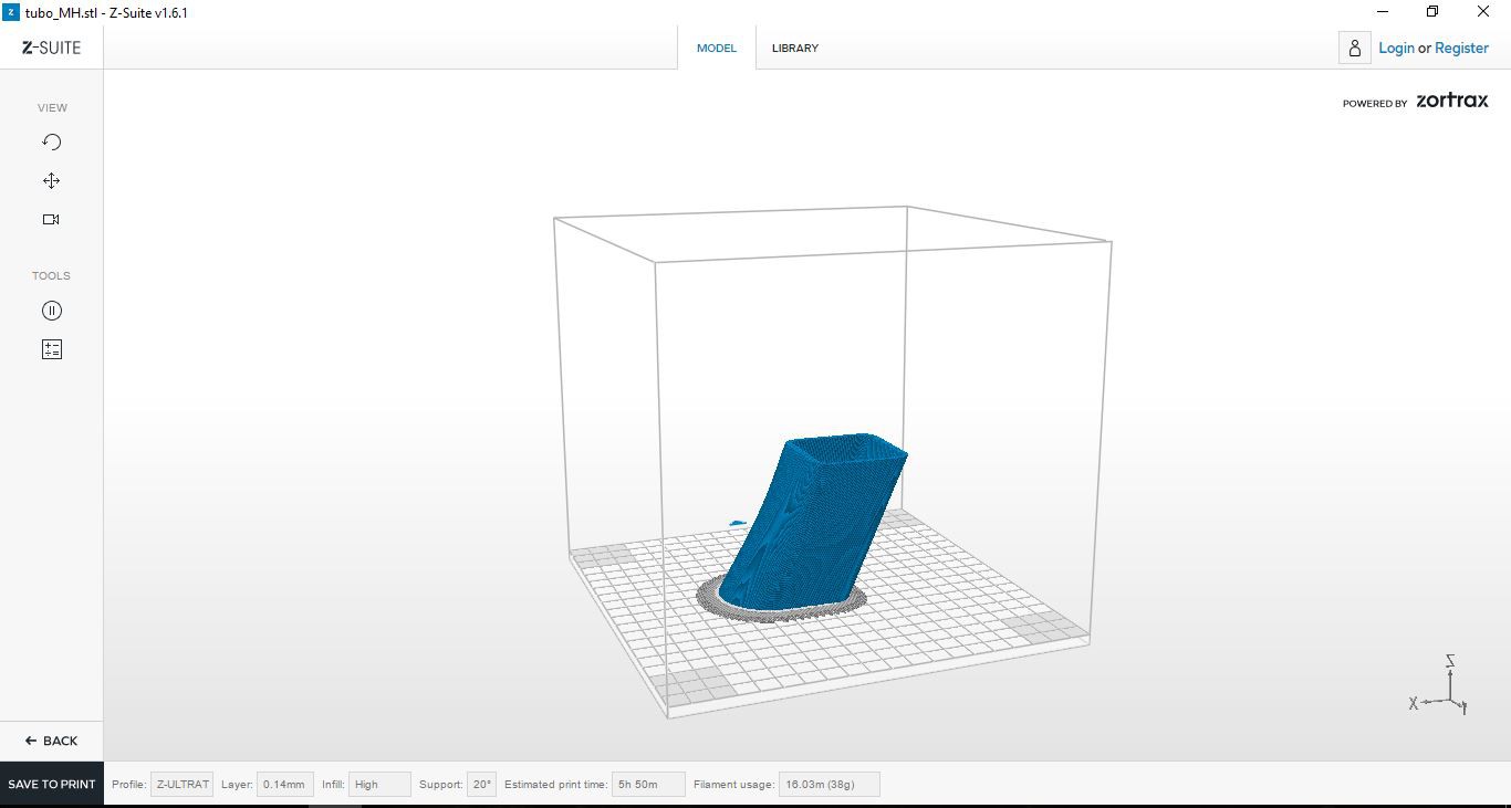
In this case we have chosen a printer of the mark Zortrax, in particular Zortrax M200. The printer includes a program, Z-Suite, with which will determine the impression. Open the program and import the piece. Place the piece in the environment of the program in such a way that the time of impression and the material of support be the possible minor.
![]()
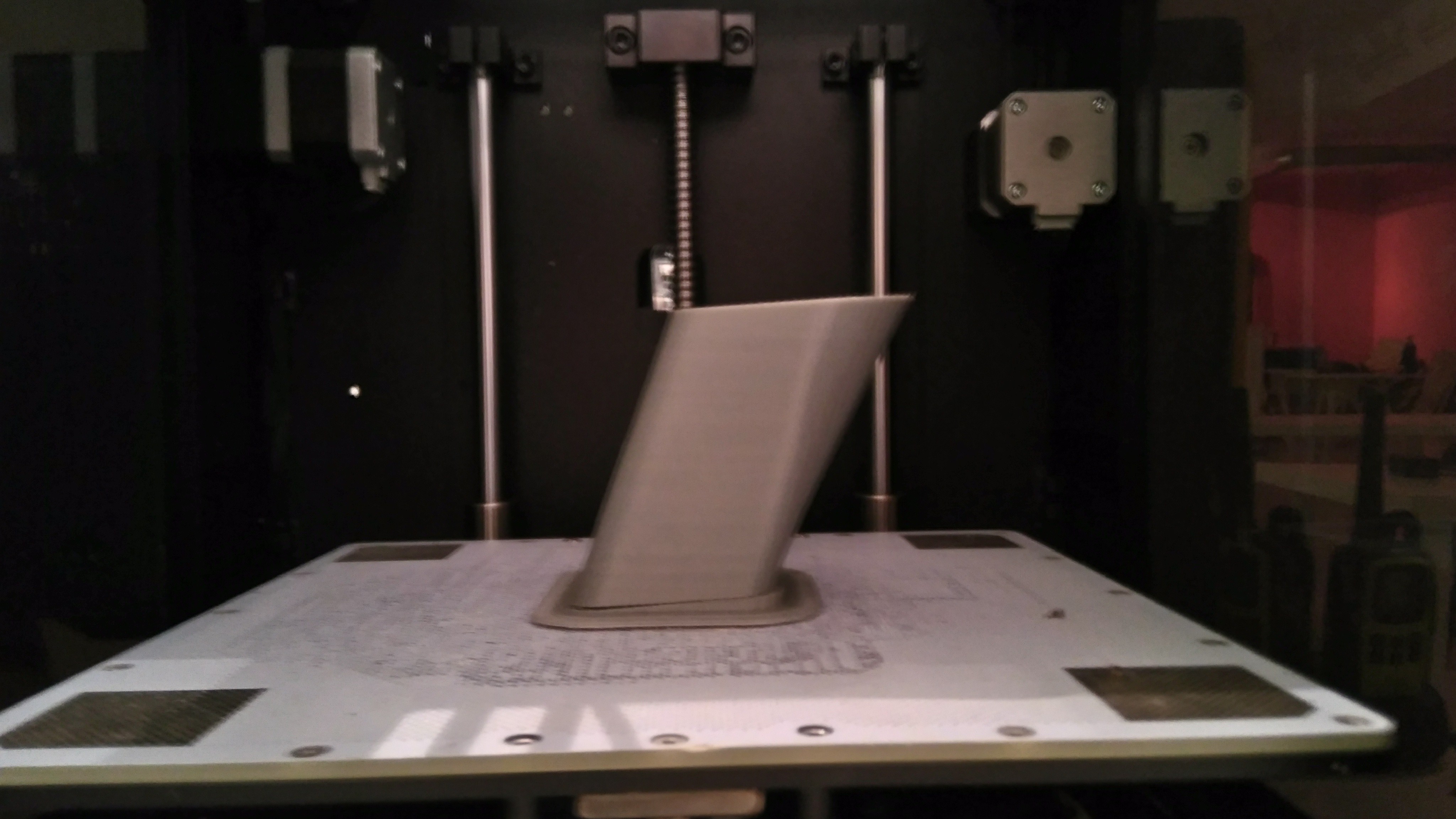
Introduce the resultant file in the printer 3D across a card SD and initiate the impression.
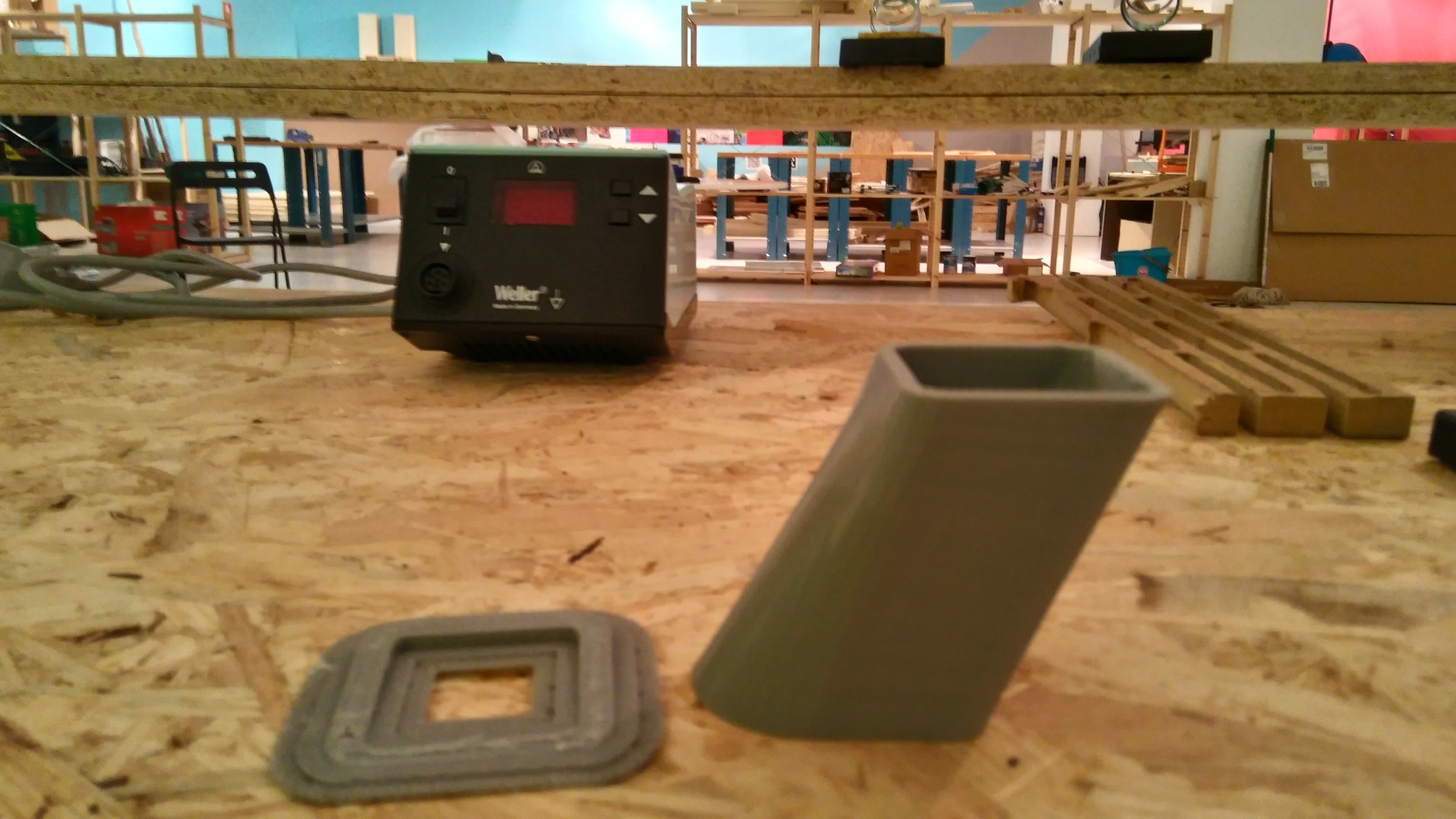
The printer will create the piece and the support material. When it finishes the impression withdraw the piece and extract the material of support manually and the piece is already ready to be installed.
![]()
![]()
-
8Step 8
ASSEMBLY OF PRINTED PROFILE 3D PARTS
An alternative way of building the profile is a 3D printer. Previously has been designed with the software Catia. The following video explains the Assembly of these parts.
-
9Step 9
MOUNTING OF THE PROFILE AND THE BALANCE
In the next video we explain how mount the balance and the profile.
CierzScience Tunnel
A wind tunnel to study the behavior of the airflow about a study object to simulate the behavior of this object in a real situatIon
Discussions
Become a Hackaday.io Member
Create an account to leave a comment. Already have an account? Log In.