Close
0%
0%

Axis

(Another) Homemade pick and place machine

Similar projects worth following
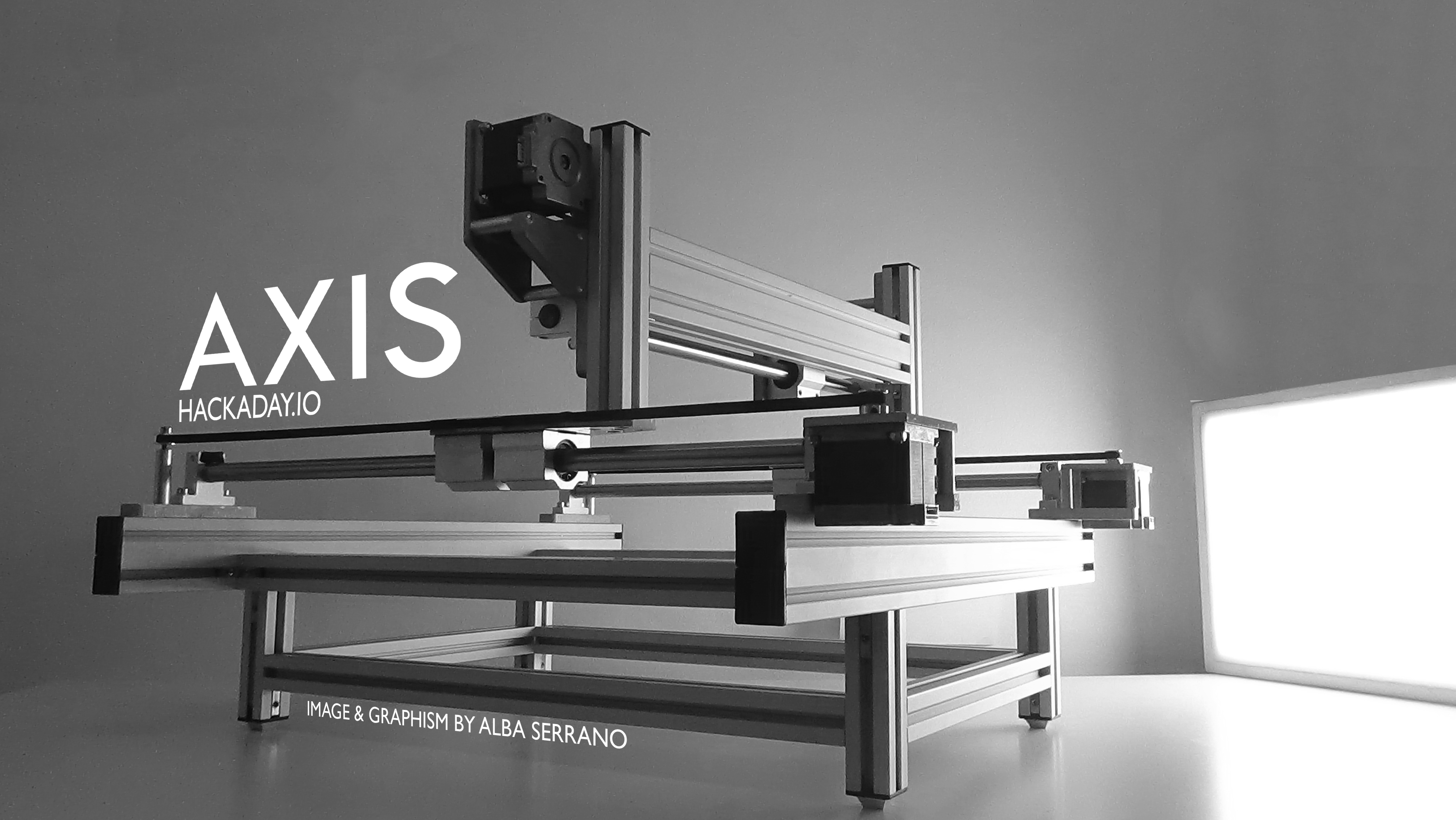
AXIS is a project for a pick and place machine ― entirely built from scratch. Uses only standard components, and with a reduced amount of machined parts.

The project is more ambitious. The idea is to have several modules (Z-axis) interchangeable: for instance a pick and place module, a 3D printer module, or even a PCB engraver ― I started with pick and place module.

All software tools used are free of cost (or lite versions of commercial tools.). I have experience with Microchip processors (PIC32), and X32 compiler. I used EAGLE for control hardware design.

All mechanical parts are from eBay (Chinese components: Bearing, linear guides, etc), recycled (Step motors, bolts, pulleys, etc), aluminum homemade parts (I have a lathe and driller) or outsource water-jet cutting service.

Goal:

Design and construction of the machine, the control software and utility applications. There are some changes from the beginning.

Why:

  • For use in my work
  • For hobby
  • And definitely because I can.

Modules/Parts:

Mechanical Hardware:

  • Frame
  • Y-Axis
  • X-Axis
  • Z-Axis/Picker
  • Feeders

Electronic hardware:

  • 4 axis motion control board by software STM32F (First option)
  • 4 axis motion control board by STM32F and FPGA. Written in C++ and System Verilog. (Advanced option)

Embedded software/softcore:

  • Motion controller written in C++ and SystemVerilog
  • EOS operating system. (EOS on my GitHub channel)

Desktop software

  • Application control for pick and place operations.
  • Utility tools for data extraction from schematics and pcb (EDATools on my GitHub channel).

Tools used:

Mechanical design:

  • FreeCAD
  • LibreCAD

Electronic design:

  • Eagle (Schematic & PCB)
  • Kicad (Schematic & PCB)
  • Quartus (FPGA sintesis)
  • Verilator (FPGA simulation and verification)

Windows software design:

  • Visual Studio 2019
  • Avalonia GUI library

Embedded software design:

  • STM32CubeIDE (Free STM32 compiler-ide, eclipse based)

Hardware tools/kits used:

Hardware developemen boards/kits:

  • Terasic DE0 Nano
  • STM32F746G-DISCO

Information sources

  • VBesment blog This is the main source of information about motor control and trajectory interpolation. I writed a new version of motion control based in this work.
  • Brian Dorey blog

AXIS-LimitSensor.rar

Schematic and board in Eagle format.

RAR Archive - 11.73 kB - 08/15/2019 at 10:38

Download

  • 3 × Step motor NEMA23 Step motor for X and Y axes. The Y axe uses two motors
  • 1 × Step motor NEMA17 Step motor for Z axis
  • 1 × Step motor NEMA11 holow shaft Step motor por rotate nozzle
  • 3 × Motor driver 2M542 or similar Drivers for NEMA23 motors
  • 1 × 36V/9A power supply Power supply for axes motors and drivers

View all 15 components

  • Eppur si muove!

    Rafael Serrano01/21/2021 at 20:17 0 comments

  • Updates on GitHub

    Rafael Serrano10/27/2019 at 11:28 0 comments

    Today I've added links to github for the operating system, pcb tools and some other utilities for the project.

  • Limit sensors

    Rafael Serrano08/11/2019 at 19:36 0 comments

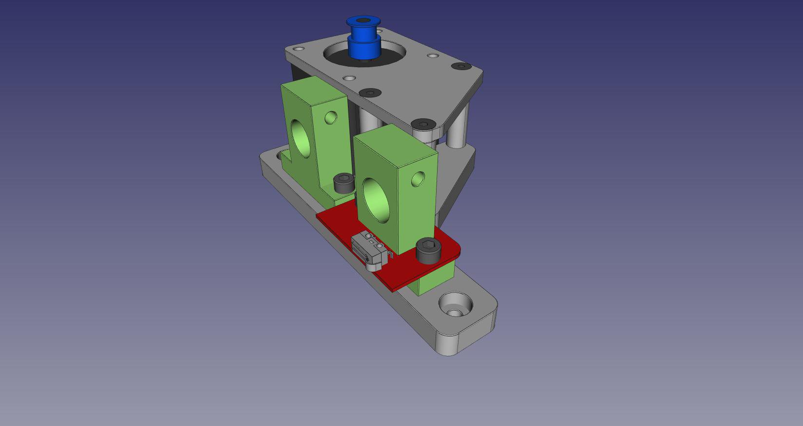
    Lately this week I've installed the X and Y axis limit sensors. Each sensor is mounted into the supports of the linear guides. Said sensors have each two LED's indicators and work at 5 volts  this can be changed to any voltage, though.

    Thera are a RAR archive with schematics and board files in Eagle format.

  • Basic structure finished

    Rafael Serrano08/04/2018 at 10:21 0 comments

    After almost two years, the basic structure of the project is finally finished  ― axes X and Y.
    It is necessary to fix some details of the CAD files. Also, the list of materials has to be written as well. From now on, I will continue to develop the electronic controls of the motors and limit detectors.

    As for the Z axis, it is not yet decided how to implement it and is still under study.


    The Axis V1.0:


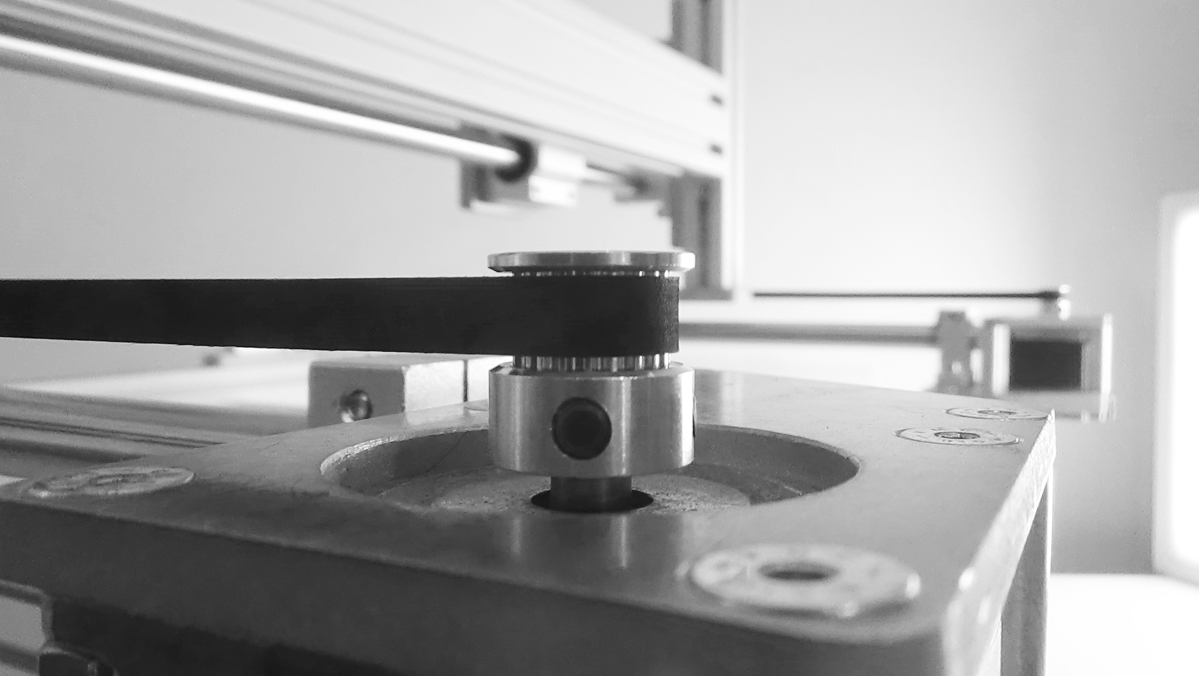
    Y motor detail view from rear:


    Y slider:


    Base structure:


    Y motors:


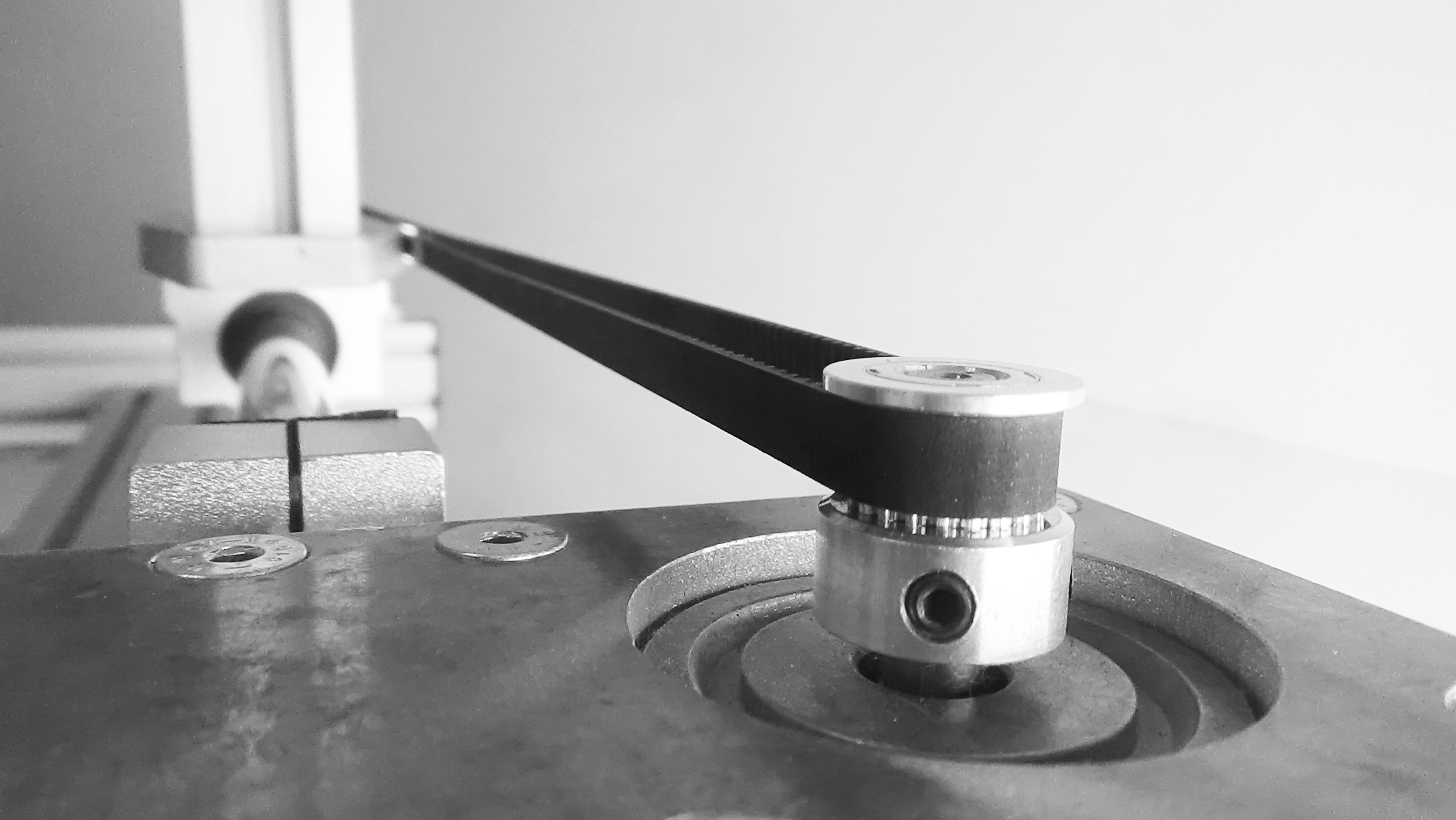
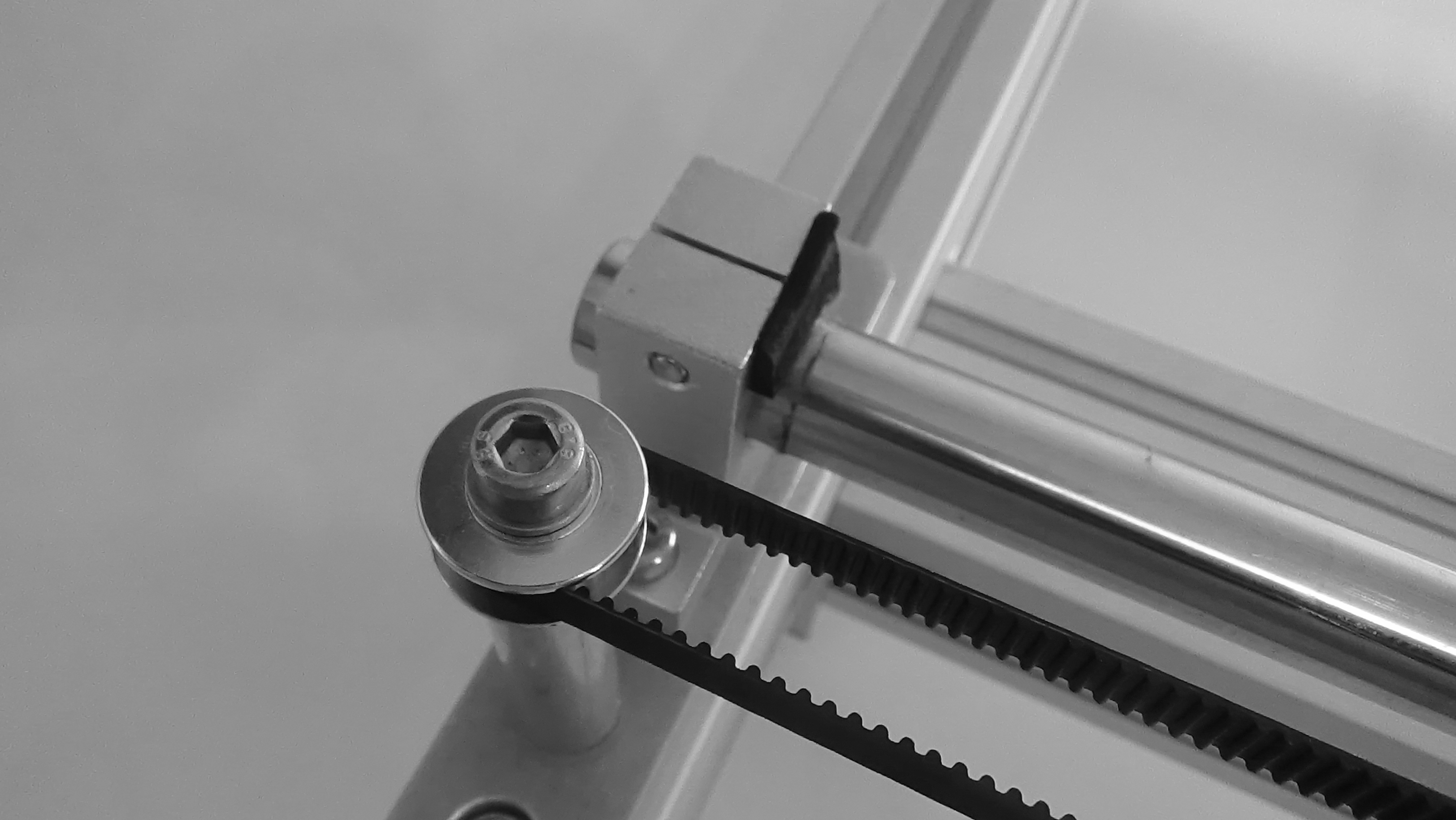
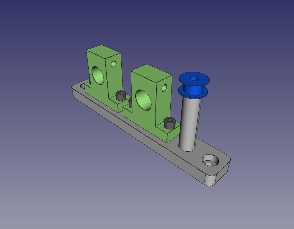
    Y free pulley detail:


    X motor:

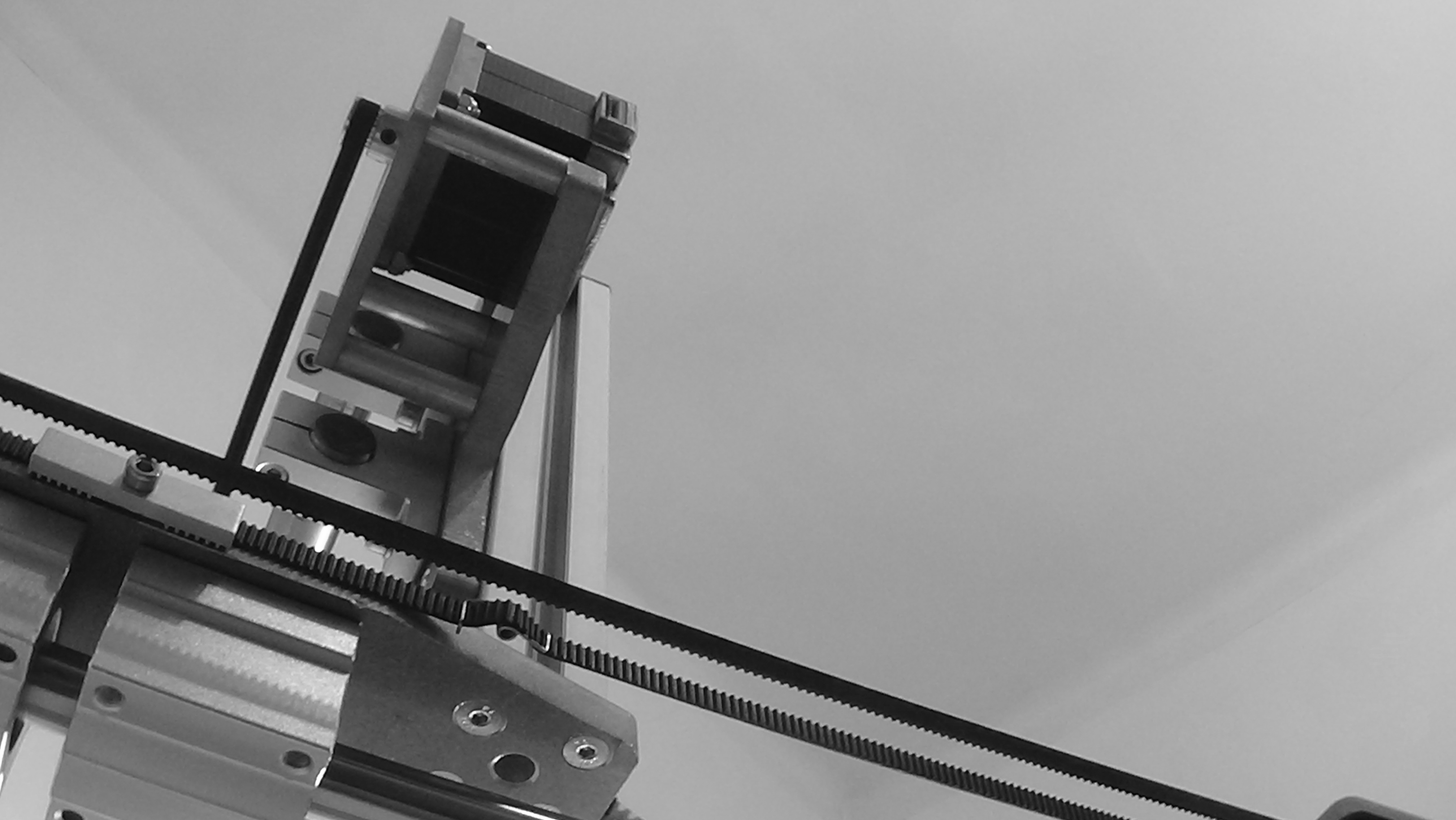
    X axis from bottom:

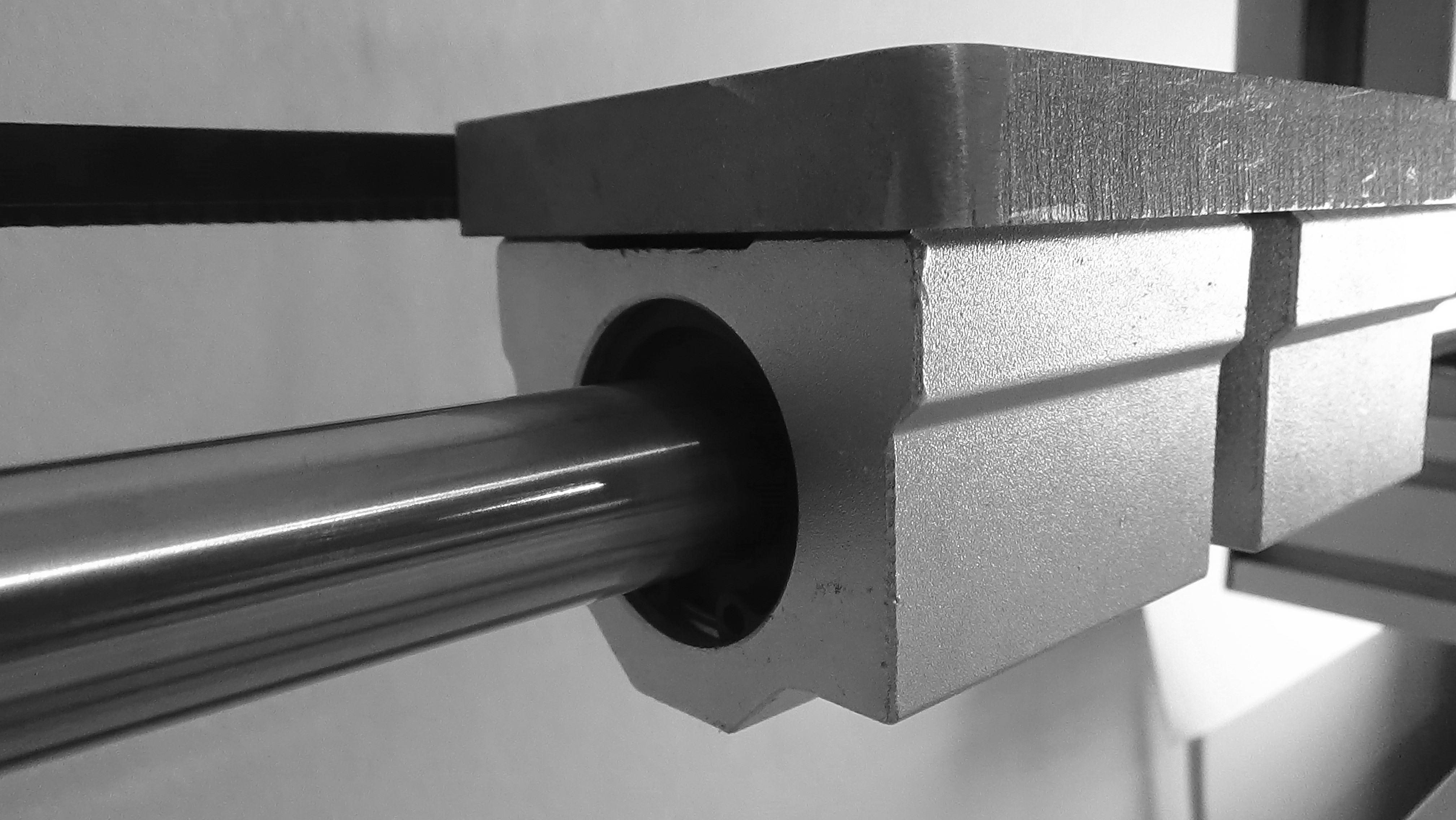
    Y slider detail:

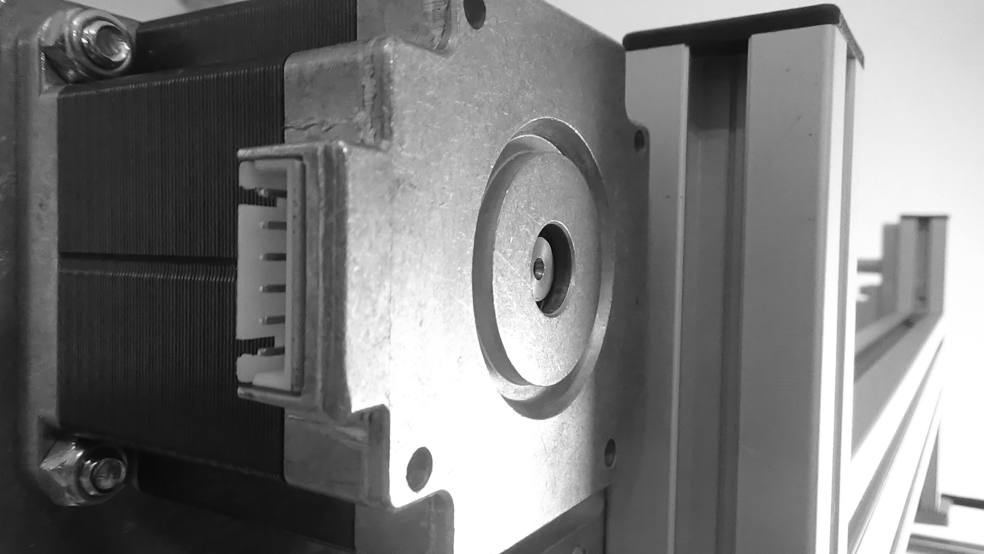
    View of X axis from motor side:

    That's all for now. Follow the project for more updates.

  • The last axis changes details

    Rafael Serrano04/01/2018 at 15:59 0 comments

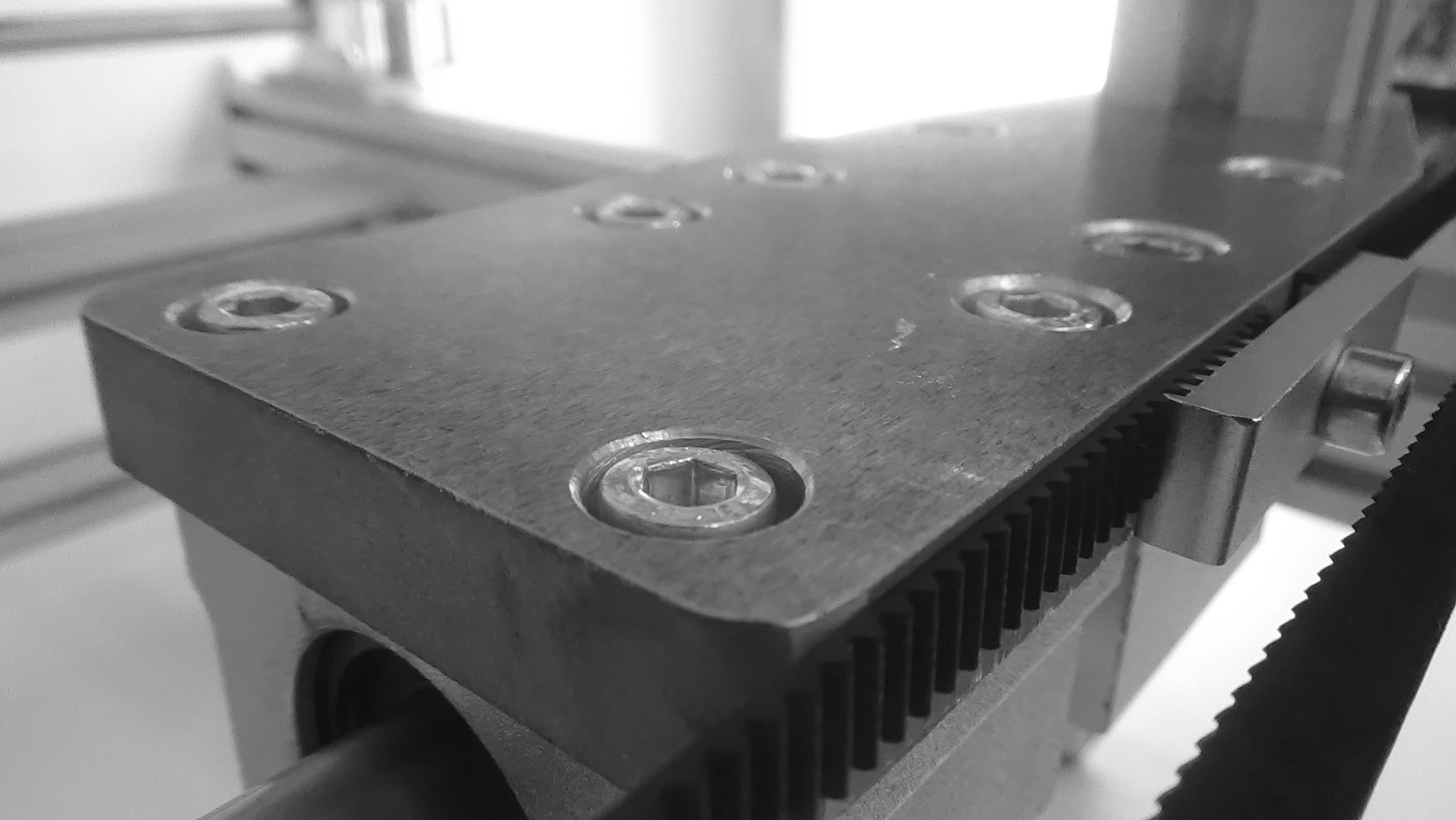
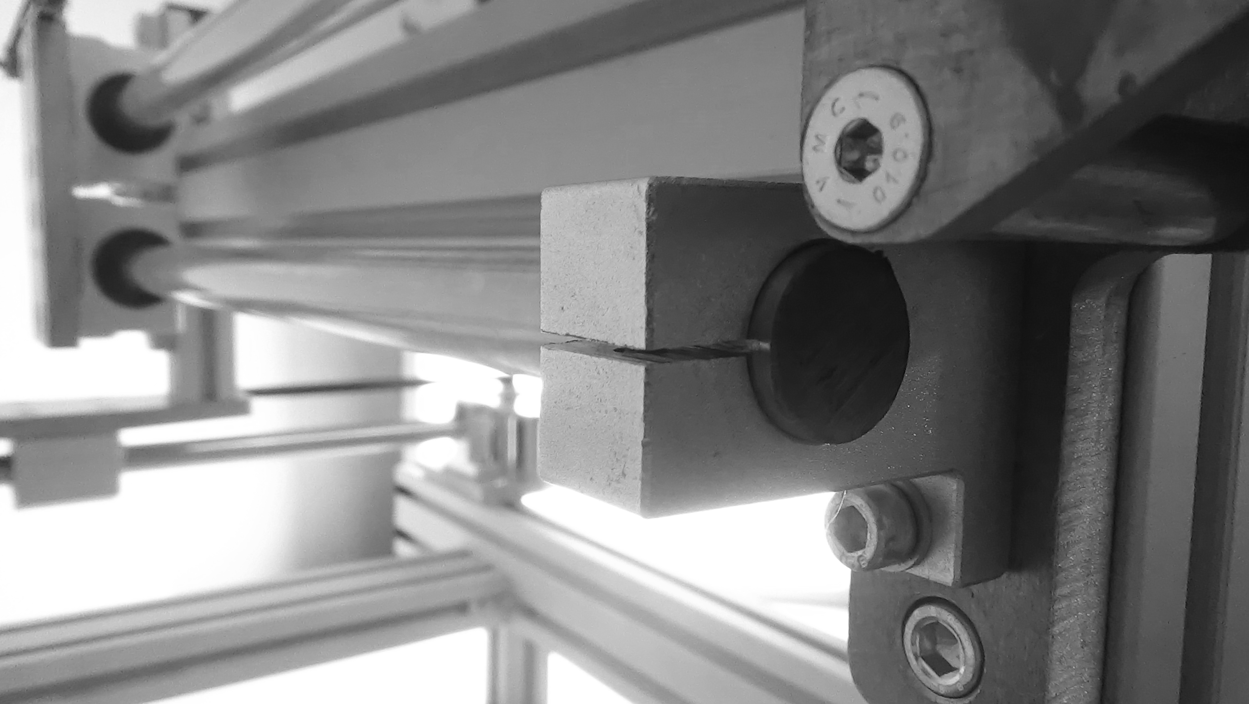
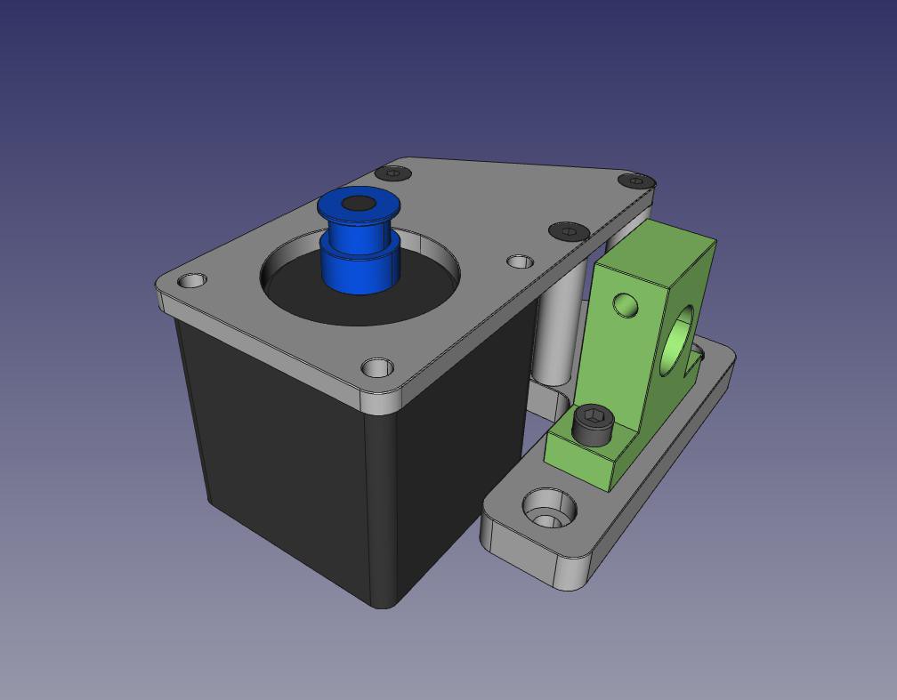
    Y axis motor:

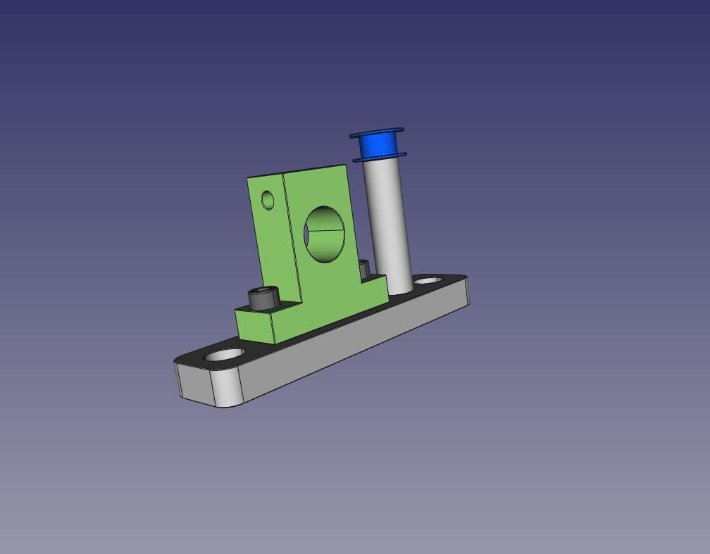
    Y axis pulley:

    X axis motor:

    X axis pulley:

  • Latest design changes.

    Rafael Serrano03/31/2018 at 20:15 0 comments

    After a few months of inactivity, I continue with the Axis project.


    Y axis:

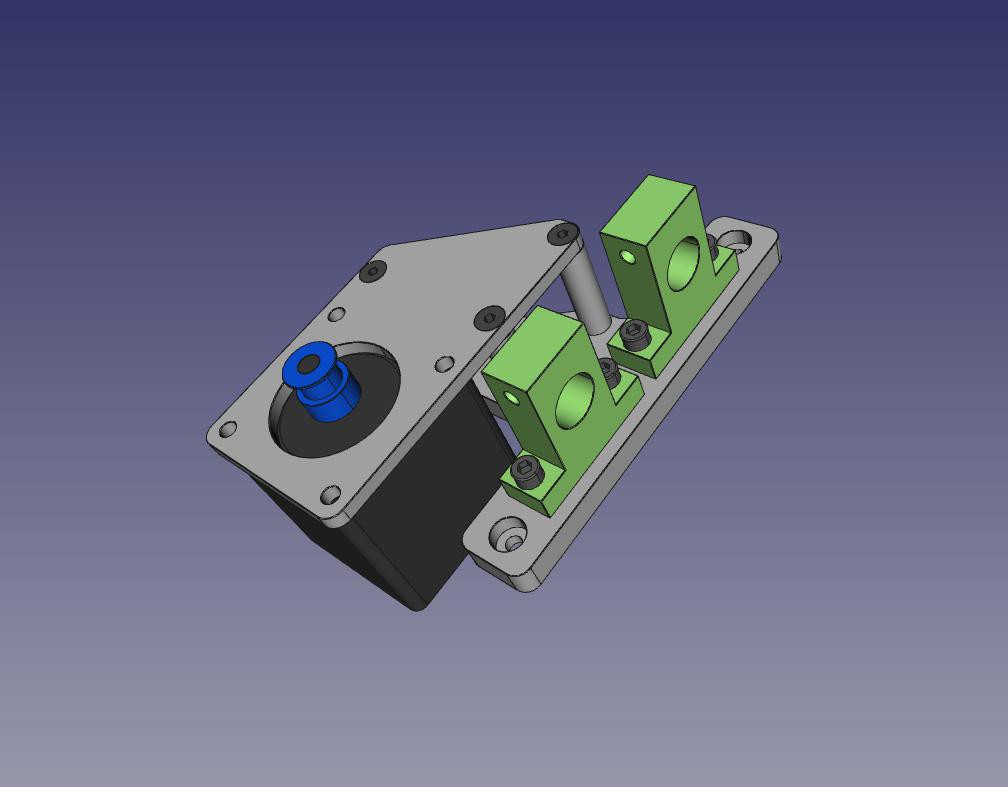
    • Change in the system of hooking the drive belt, which involves raising the motor, and the free pulley.
    • Change in the support plate of the X axis


    X axis:

    • Remodeling complete, to work with the guides in vertical.
    • Use the same philosophy as in the Y axis


    Z axis:

    • Replanting the system. To study.

    In a few days the base structure and the Y axis will be completed.

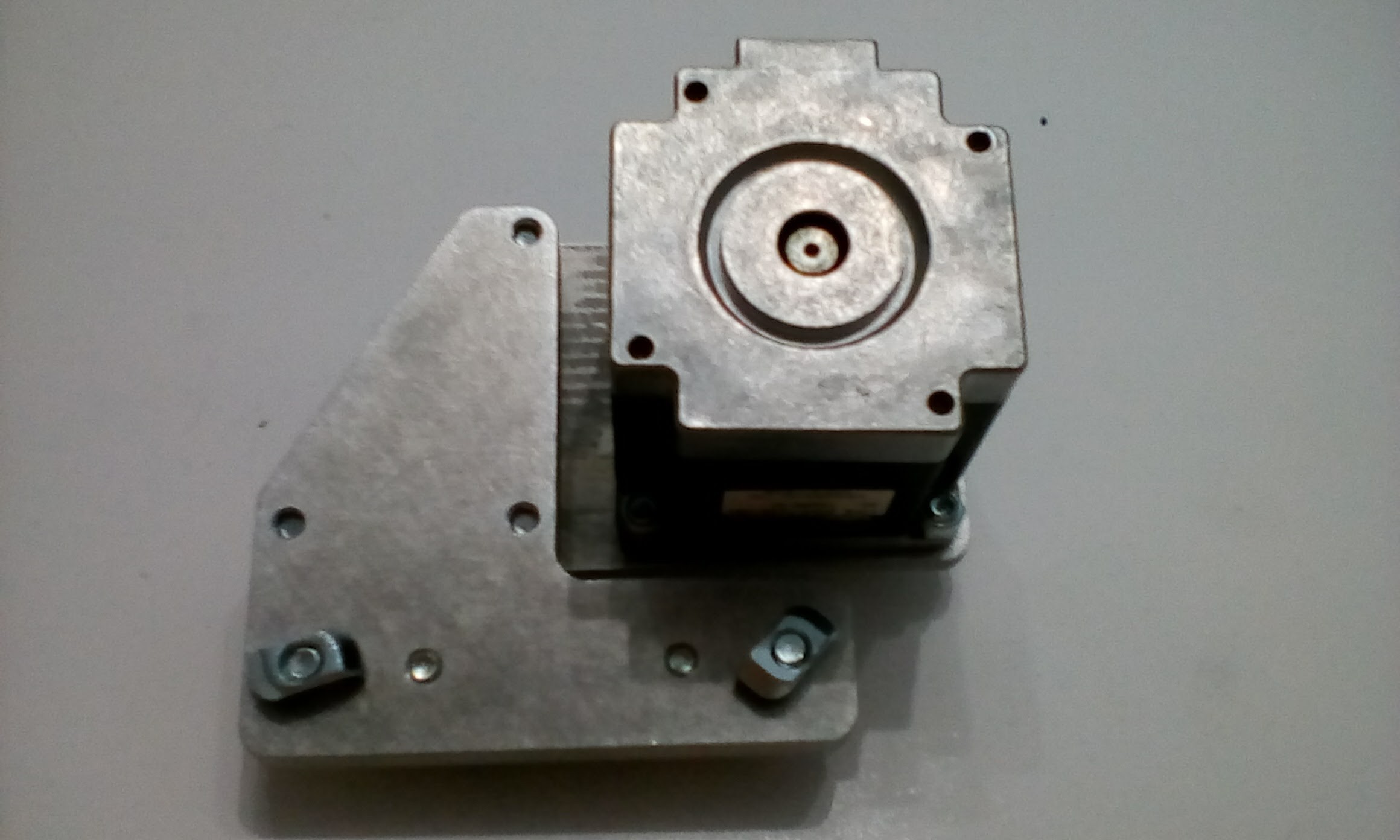
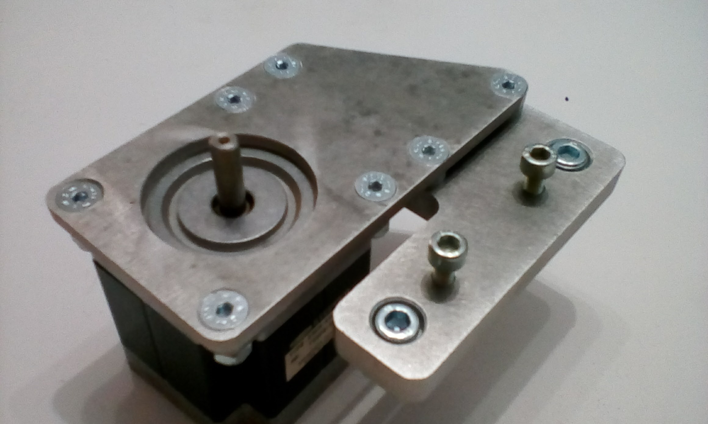
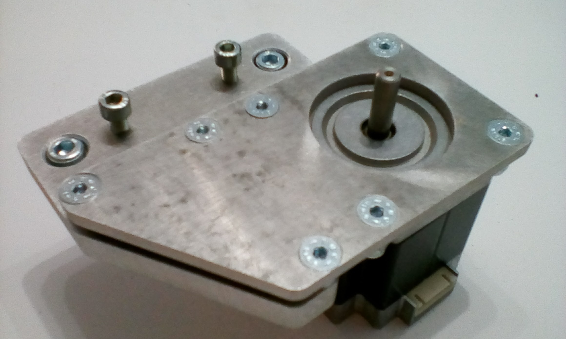
  • Y-Axis motor module

    Rafael Serrano07/30/2017 at 12:52 0 comments

    Today I finished machining and mounting the Y-axis motor module. All measurements and tolerances seem correct. Anodizing is missing, but we'll leave it for later. In a few days I will have the entire structure.

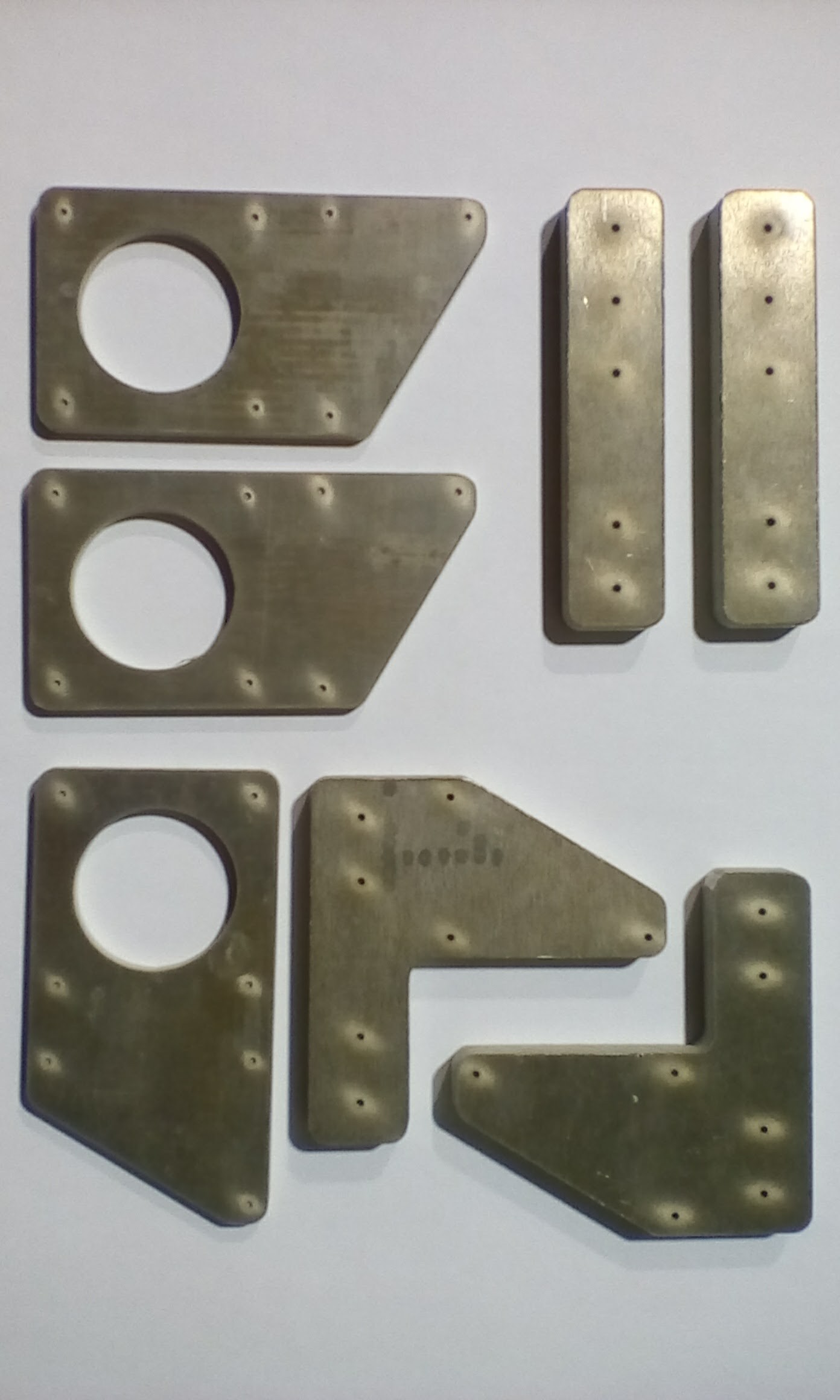
  • Aluminium parts for Y-Axis

    Rafael Serrano07/02/2017 at 16:42 0 comments

    I've finally received the aluminum parts for the Y-axis assembly. They had been cut by water-jet. The holes and threads need to be machined.

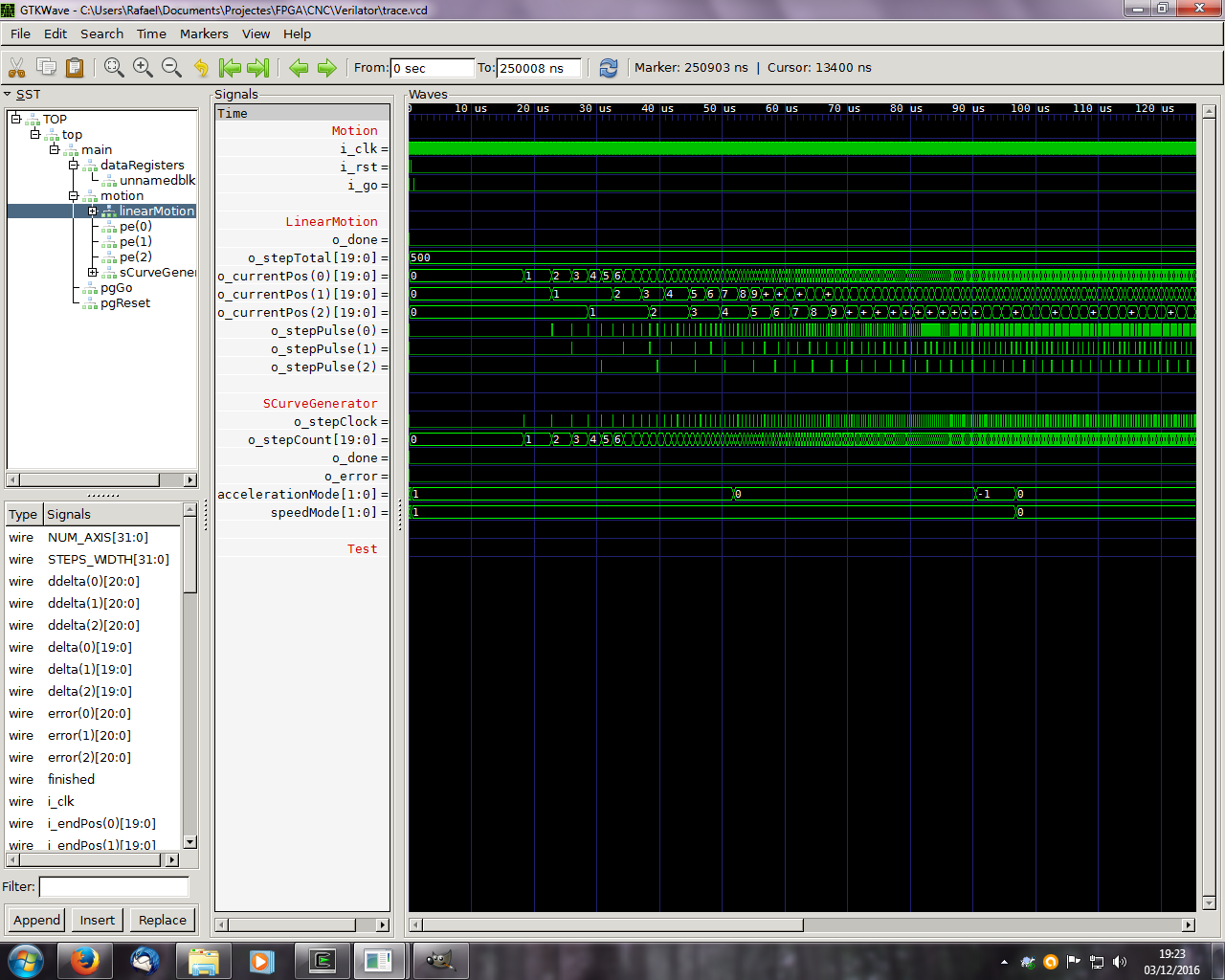
  • 3 Axis FPGA controller

    Rafael Serrano12/03/2016 at 18:48 0 comments

    At the moment I have finished the prototype 3-axis motion controller with a DE0-Nano board. The simulation was performed with Verilator, and the synthesis and programming with Quartus-II v13.1.
    The model is written in system verilog. It includes several modules, the most important of which SCurveGenerator, LinearMotion and ALU, with a Look-Ahead carry.

    The system generates the STP and DIR signals for three step motor controllers. As parameters requires JERK, and the definition of S ramp. The process starts when receiving the GO signal.

    I forgot to mention that the number of axes can be configured using the NUM_AXIS parameter from 2 to 16


    Soon more and better

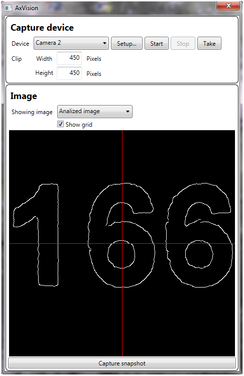
  • AxVision: Vision experiments (2)

    Rafael Serrano10/16/2016 at 12:12 0 comments

    Et voila!

    Edge detection on a clear black & white image, using an "USB microscope cam".

    Next:

    • Detection of rectangles (Components) and circles (Fiducials).
    • Compute centroid.
    • Compute angle deviation for rectangles.
    • Make real scale grid for calibration.

    Brainstorm:

    • Test type of ilumination (Red leds or white leds). Actually the microscope use 3 white leds.
    • Use hardware system FPGA+CAM (DE0 Nano) or software system (OpenMV) as an independent detection module. Expensive but beautifull.

View all 15 project logs

Enjoy this project?

Share

Discussions

smtguide wrote 08/12/2017 at 16:06 point

Hi,

Thanks for sharing I really like your project it looks simple and efficient, would like to know if you could help me design similar project but head controlled by joystick (X-Y axis) and nozzle controlled by stick as well (Z axis).

  Are you sure? yes | no

Rafael Serrano wrote 03/31/2018 at 20:21 point

Sorry, I've been away for a few months and I have not been able to review the project. No problem, in a few days I will publish the design in GitHub, as well as photographs and videos.

Regard

  Are you sure? yes | no

Similar Projects

Does this project spark your interest?

Become a member to follow this project and never miss any updates