 Peter McCloud
-
1Step 1
THINK BEFORE YOU START
Before you start this project, take some time to REALLY think about what you're about to build. Seriously, this is a flying machine that weighs more than most people and runs on gasoline, a chemical that the states of Oregon and New Jersey have deemed too dangerous for the average citizen to pump into their own car.
While Goliath is a big and powerful, it's only as dangerous as the user. As you build, test and fly your giant quad copter be mindful of your safety and the safety of others.
-
2Step 2
BUILDING THE COMPOSITES
Building the composite pieces requires the longest amount of lead time. It's recommended to start these pieces first, and the rest of the components likely be built while waiting for the composite pieces. Components made from composites are:
- Propellers
- Ducts
- Control Surfaces
-
3Step 3
BUILDING THE UPPER FRAME
Tools - Miter Saw, Jig Saw or Tin Snips, File, Drill with #30 drill bit,Rivet Puller
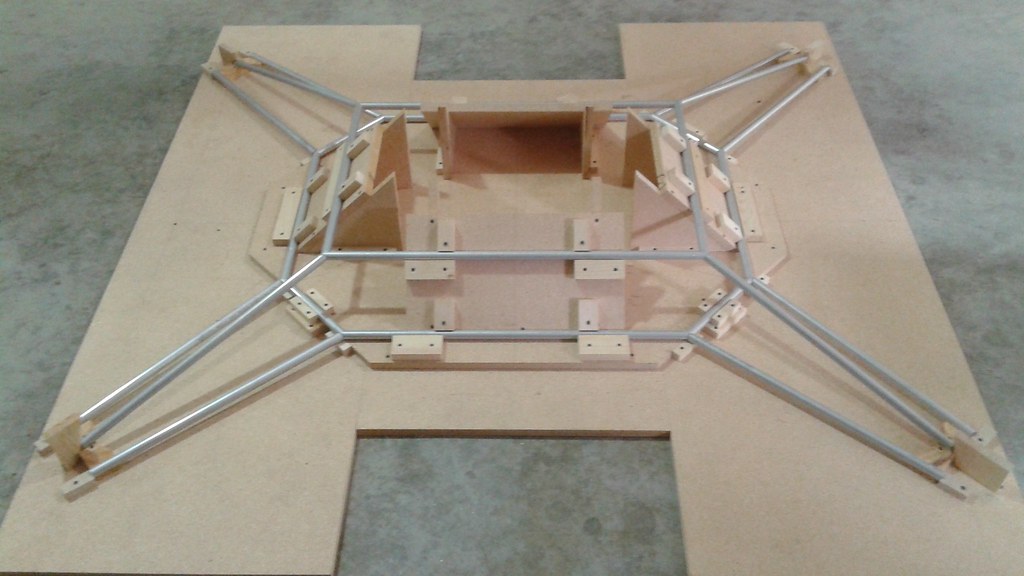
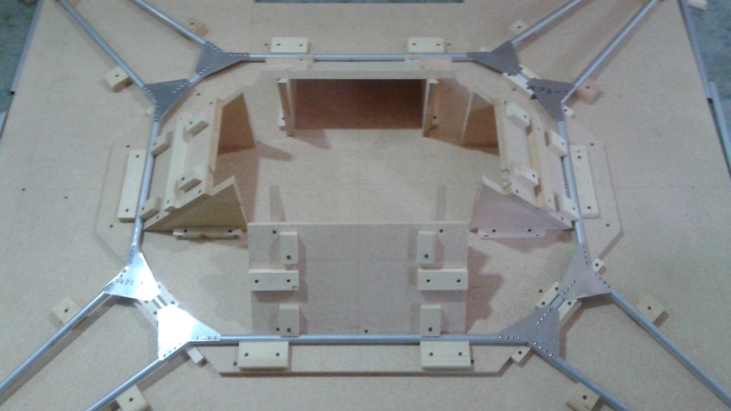
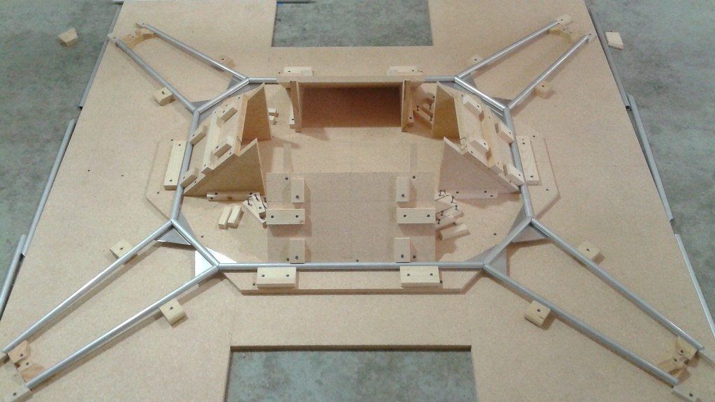
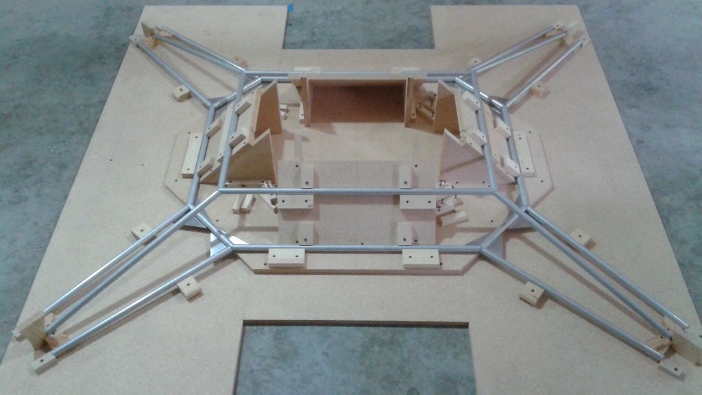
A) Build the Jig for the Upper Frame
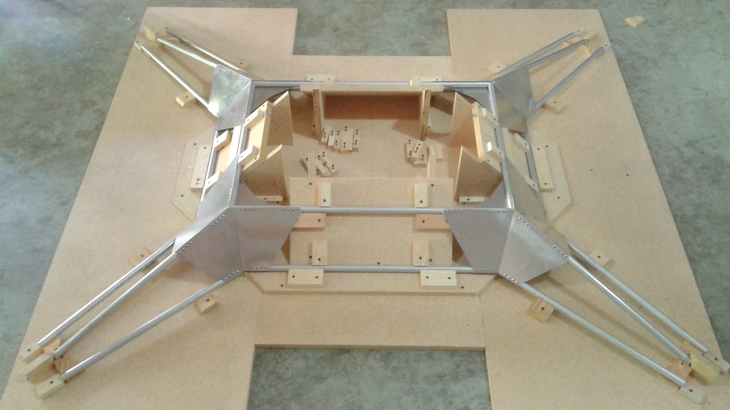
To properly build the frame, jigs are required to hold all of the frame elements in place. The jig is constructed from particle board. Below the completed jig is shown with the upper frame elements in place.
![]()
B) Cut the Upper Frame ElementsUsing a miter saw, cut all of the frame elements and place them in the jig to ensure a proper fit.
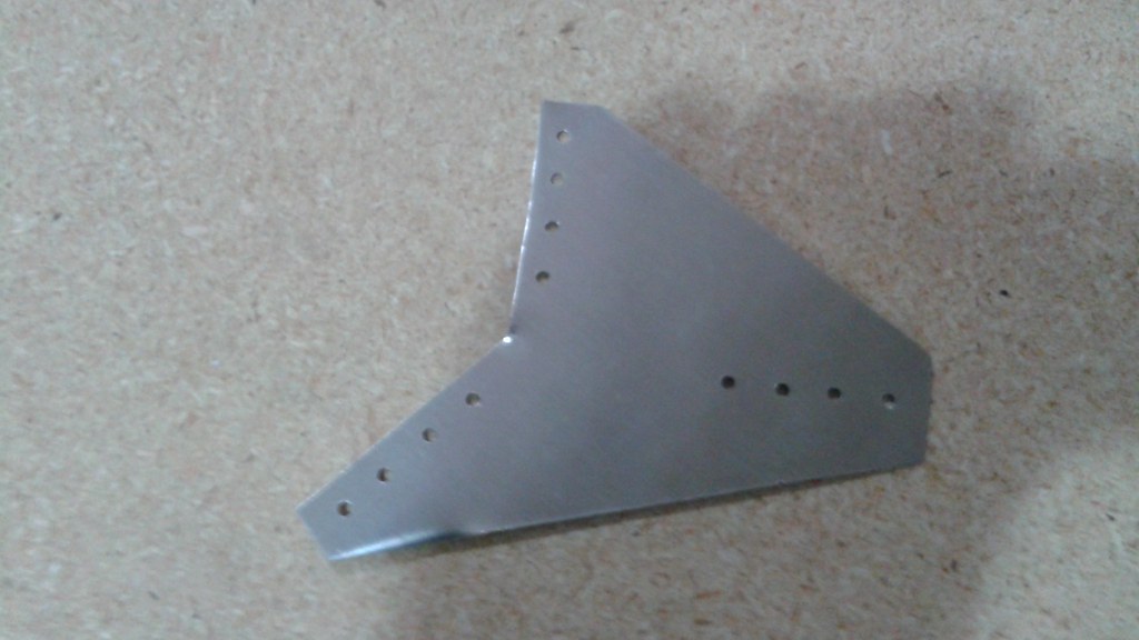
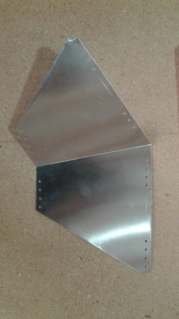
C) Cut the Common Gussets
Cut the common gussets (4 A & 4 B), layout and drill the holes with the #30 drill bit.
![]()
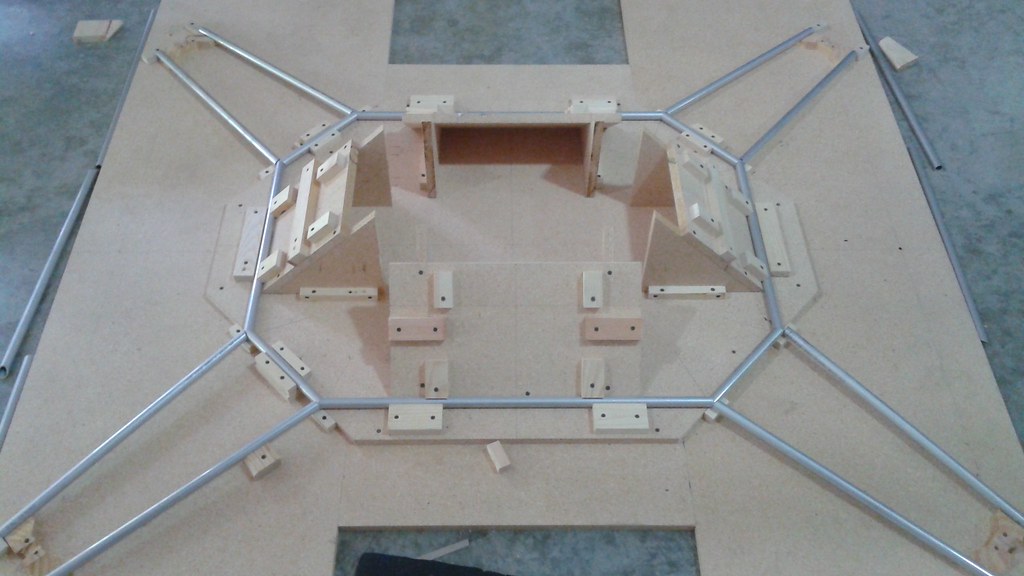
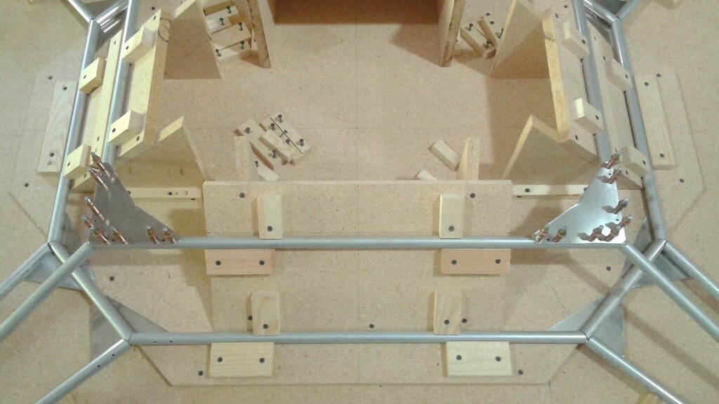
D) Assemble the Upper Deck Elements
1) Remove the frame elements for the upper ring, leaving just the pieces for the upper deck
![]()
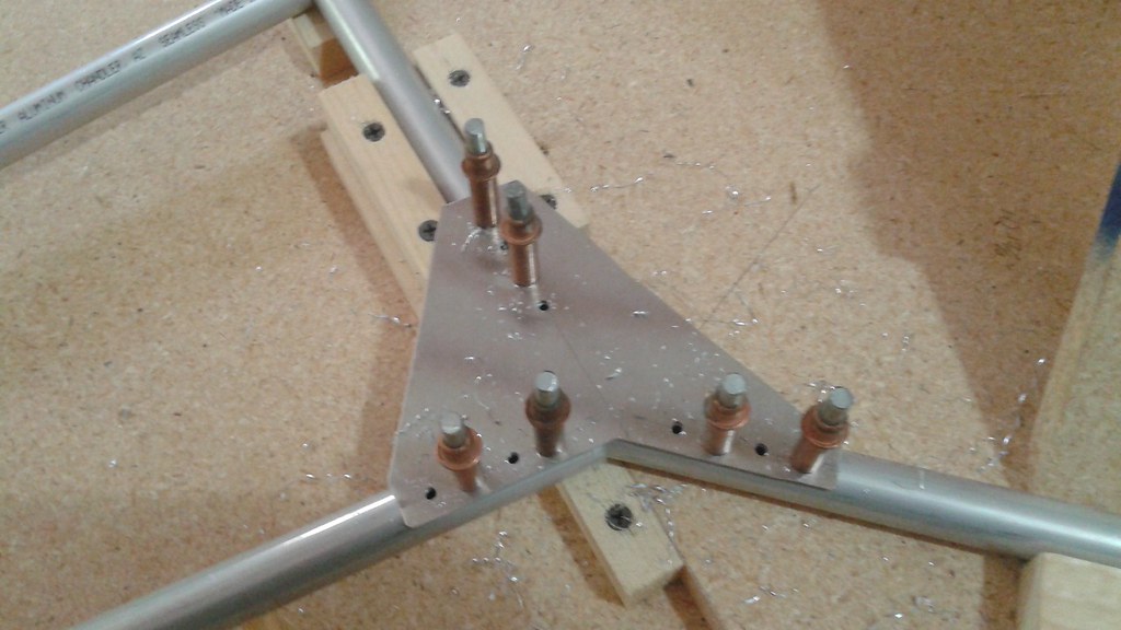
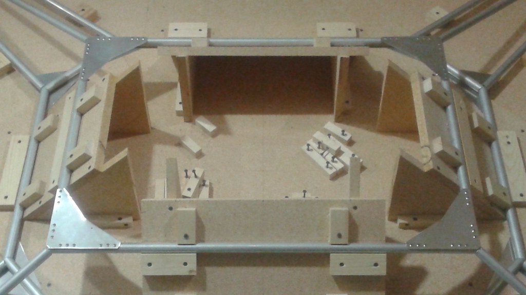
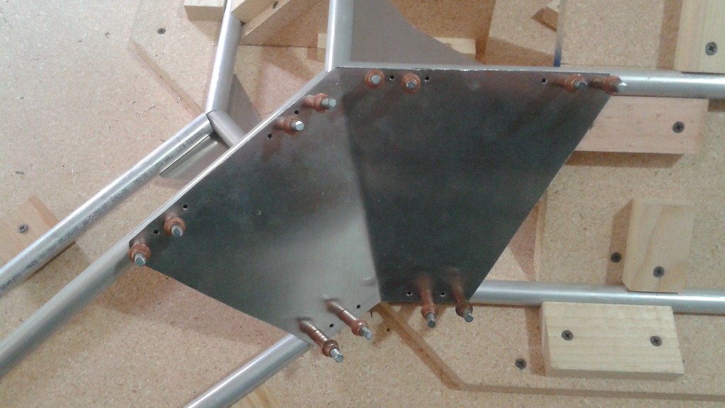
2) Clamp the common gussets in place and drill half of the holes into the frame. Use Clecos to fill in the holes as you go.![]() 3) With half of the holes filled with Clecos, drill the remaining holes and fill them with rivets.
3) With half of the holes filled with Clecos, drill the remaining holes and fill them with rivets.![]()
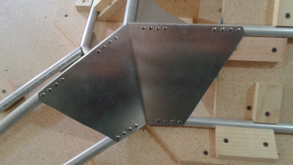
4) Remove the Clecos and fill in the remaining holes with rivets.![]()
5) Remove the upper deck from the jig, flip it over and place it back in the Jig![]()
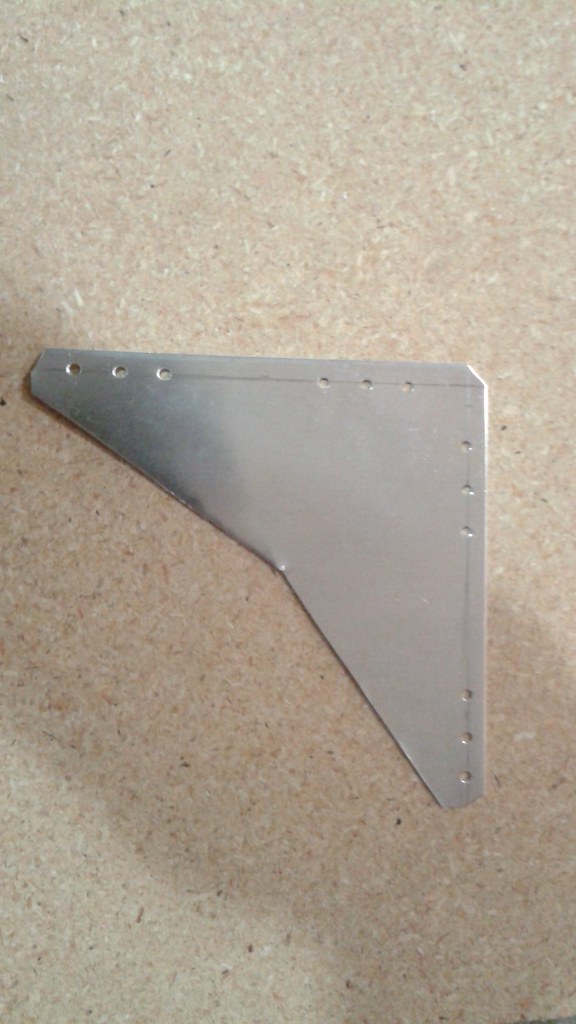
E) Cut the Corner Gussets
![]()
F) Assemble the Upper Ring
1) Place the remaining frame elements back in the Jig
![]()
2) Attach the corner gussets
![]()
![]()
G) Join the Upper Ring to the Upper Deck
1) Cut the Angle Gussets
![]()
2) Attach each of the angle gussets
![]()
![]()
![]()
The Upper Frame is now complete and can be removed from the Jig![]()
-
4Step 4
Mounting the Engine
Tools: 5/16" Wrenches and Sockets
A) Prepare the Engine
1) Check the wiring and redo the connectors
2) Remove the excess choke hardware
3) Remove the excess throttle hardware
B) Bolt the Engine to the Frame
Using (4) bolts, (4) lock washers and (4) hex nuts, bolt the engine to the frame
C) Attach the Main Pulley to the Engine Shaft
Place the Main Pulley onto the Main Pulley Bushing, but do not tighten them together. Place the 1/4" key onto the engine shaft keyway and slide the bushing over the engine shaft with the keyways aligned. Tighten the bushing bolts.
-
5Step 5
Building the Exhaust
Tools: Chop Saw or Reciprocating Saw, Files, Welder, Torx (T40) bit, Socket Wrench, 1/4" and 7/16" sockets
A) Cut the materials
Using the chop saw or reciprocating saw, cut the 1" diameter U-Turn and the 135 Bend, as well as the 1 1/8" adapter tube to length. File as needed to clean the cuts and to make sure the cuts are square.
B) Create the sub-assemblies
- Tack weld The U-Turn and the 135 Bend together
- Tack weld the adapter and the universal flange
C) Join the sub-assemblies together
Place all the parts in place on the frame and engine to get the proper alignment. Using a sharpie, mark the two sub-assemblies to allow them to be aligned together correctly. Remove them and tack weld.
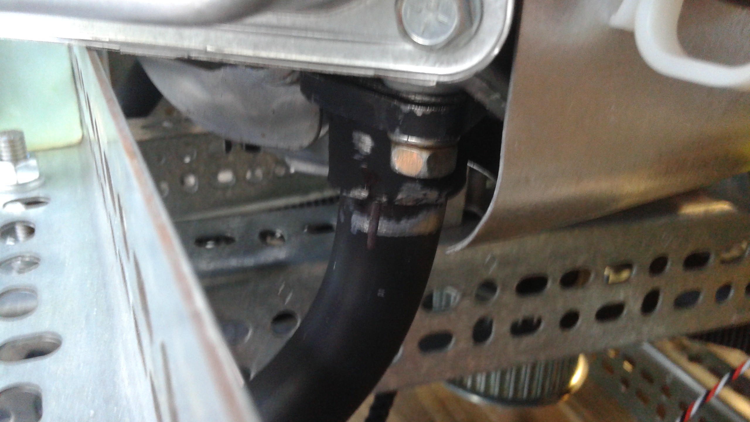
![]()
D) Make the Final Welds
With all of the tack welds made, place the exhaust pipe back on the vehicle, and tighten all the mounting bolts to make sure it's in the correct place. Once the fit is confirm and the mounting locations have been double checked remove the exhaust pipe and make the final welds. Clean off the welds and make sure that there are no holes that will allow the exhaust to escape.
E) Painting the exhaust.
Using the high temperature spray paints, apply two coats of primer and two coats of paint to the exhaust pipe and the muffler.
F) Mount all of the parts
- Attach the exhaust pipe at the engine using the Torx T40 bit..
- At the aft end attach the exhaust pipe to the mount using the U-Bolt. Once the U-Bolt is through the mounting bracket, add the lock washers and the nuts. Tighten using the 7/16" socket..
- Slide the 1" diameter clamps over the mufflers and slide the mufflers over the end of the exhaust pipe. Tighten the clamps with the 1/4" socket.
-
6Step 6
Building the Belt Tensioners
-
7Step 7
Building the Propeller Assemblies
-
8Step 8
Attaching the Belts and Propellers
-
9Step 9
.....Do Other Stuff....
-
10Step 10
Engine Servos
A) Cut the sheet metal for the mounting bracket
B) Scribe the lines
C) Drill the holes
D) Cut the sheet metal
E) Bend the sheet metal
F) Mount the servos
G) Connect the throttle arms
 3) With half of the holes filled with Clecos, drill the remaining holes and fill them with rivets.
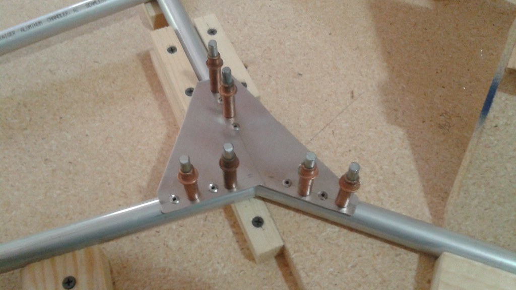

Discussions
Become a Hackaday.io Member
Create an account to leave a comment. Already have an account? Log In.
CG of whole machine should be as near to the center as possible. CG of all items/ subassemblies should be near to the CG of whole machine, or items/subassemblies should be fitted in symmetric for this reason.
Are you sure? yes | no
However I have just started reading the details provided here but I hope CG (center of gravity) of engine and fuel tank (including fuel weight) has been considered before final positioning of these 2 items.
Are you sure? yes | no