 Peter McCloud
-
Goliath Mk. III
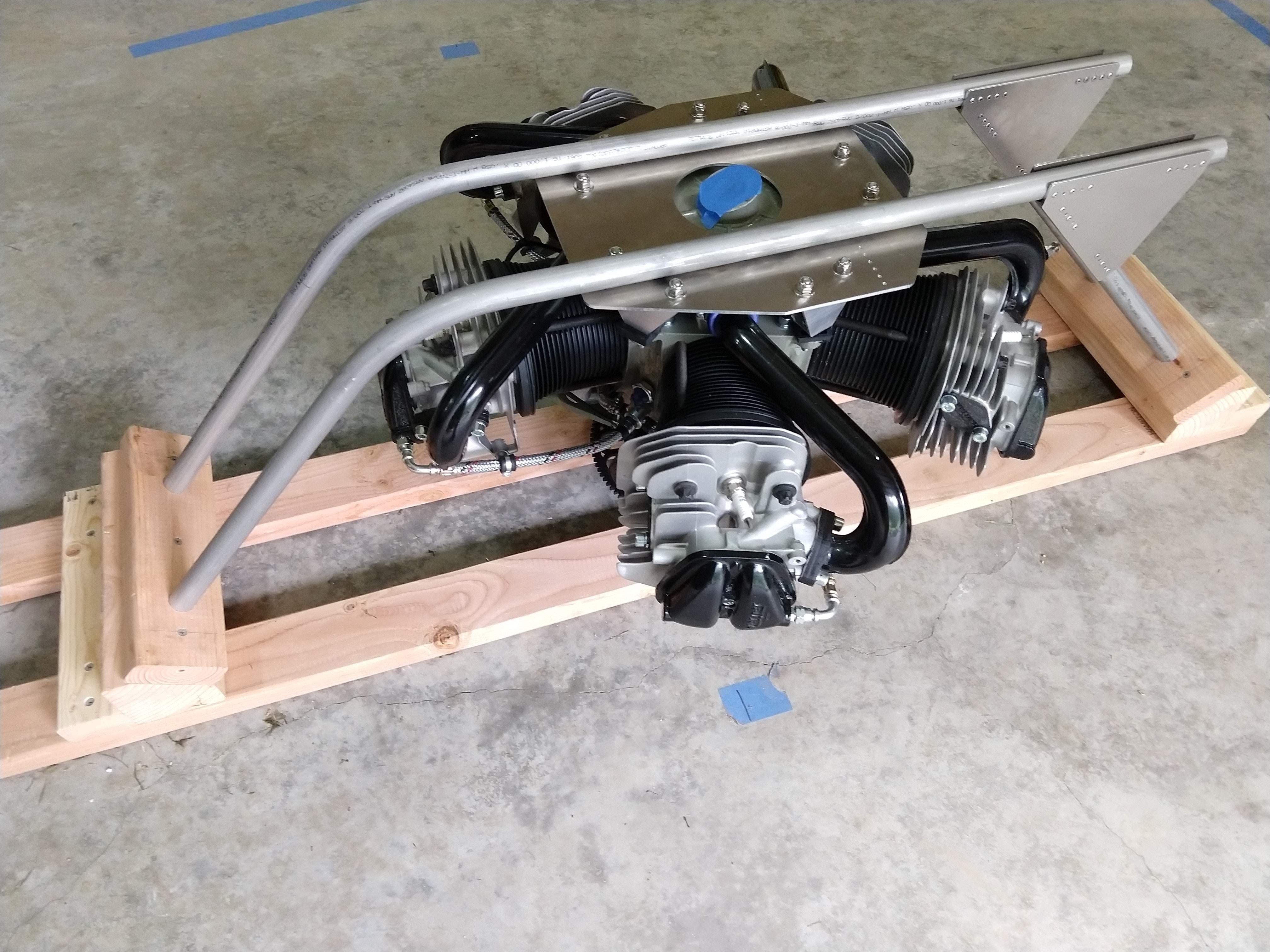
06/05/2019 at 03:36 • 0 commentsThe hardware for Titan, Goliath's bigger brother is starting to come together. The engine has arrived and the first frame elements are taking shape.
![]()
With Titan's design progressing, there's a need to test portions of the hardware before integrating the complete vehicle, particularly the rotors. Additionally, designing Titan has been educational, and some of the lessons learned can be applied to Goliath. So this summer, work will start on upgrading Goliath to a Mk. III design with an update to the drive system and 42" rotors (vs. the previous 36" rotors).
The #EVPR: Electric Variable Pitch Rotors will also receive a custom PCB designed by our very first intern. Things are falling into place to make a lot of progress this summer, so stay tuned.
P.S. If are interested in progress updates specific to Goliath, check out McCloudAero.com or follow us on LinkedIn
-
Goliath Expecting a Sibling in 2019
01/31/2019 at 18:57 • 0 commentsGoliath is still moving forward, but work has already begun on the next vehicle that will incorporate the lessons learned from Goliath Mk. I and II. Over the past few months, I've been working on the conceptual design for the new vehicle, called Titan. The design has progressed to the point that today, the deposit was placed for the engine that will power Titan.
It will be 3-4 months until the engine arrives and as the design matures, I'll be providing more details on the design. The goal is to have the vehicle assembled and begin testing by the end of 2019.
-
Pixhawk/PX4 Mixer Issues Among Other Things
11/14/2018 at 05:32 • 2 commentsOne of the advantages to using the Pixhawk is the ability to create custom control configurations. This is necessary for Goliath since it's using a single engine with variable pitch propellers. Previously, having a custom mixer wasn't necessary since the standard quad mixer worked reasonably well with the variable pitch rotors as the PWM signals map in a similar manner. The downside to using the standard mixer is that the engine speed and thrust are not coupled, which made it difficult to control the engine RPM properly. Now that all four rotors are variable pitch, the thrust and engine speed need to be coupled together, making a custom mixer necessary.
The process is supposed to be straightforward. You write a custom file, copy it to the SD card and update the configuration file on the SD card to point to the new mixer. After doing all that the rotors stopped working. After a lot of debugging and gnashing of teeth, it turns out there are currently some bugs in the PX4 build (https://github.com/PX4/Firmware/issues/8975).
The workaround is to add the mixers to the Firmware source code, and flash the updated firmware to the PX4. Makes debugging a slower process as every time I want to make a change, I have to flash the firmware versus directly editing the file on the SD card, but it's working. The issue is supposed to be fixed in one of the upcoming releases, and things can hopefully go back to normal.
At this point I was hoping to write that I have a new mixer file. Nope, that didn't happen. In the process of debugging the mixer, the Pixhawk is now refusing to arm, giving the error:
PREFLIGHT FAIL: EKF INTERNAL CHECKS
I've tried some of the easy steps to address this, but none of them worked. Since I can't arm, I can't test the custom mixer. So this needs to be addressed before I can finalize the mixer.
-
Dedicated Vehicle Mounts
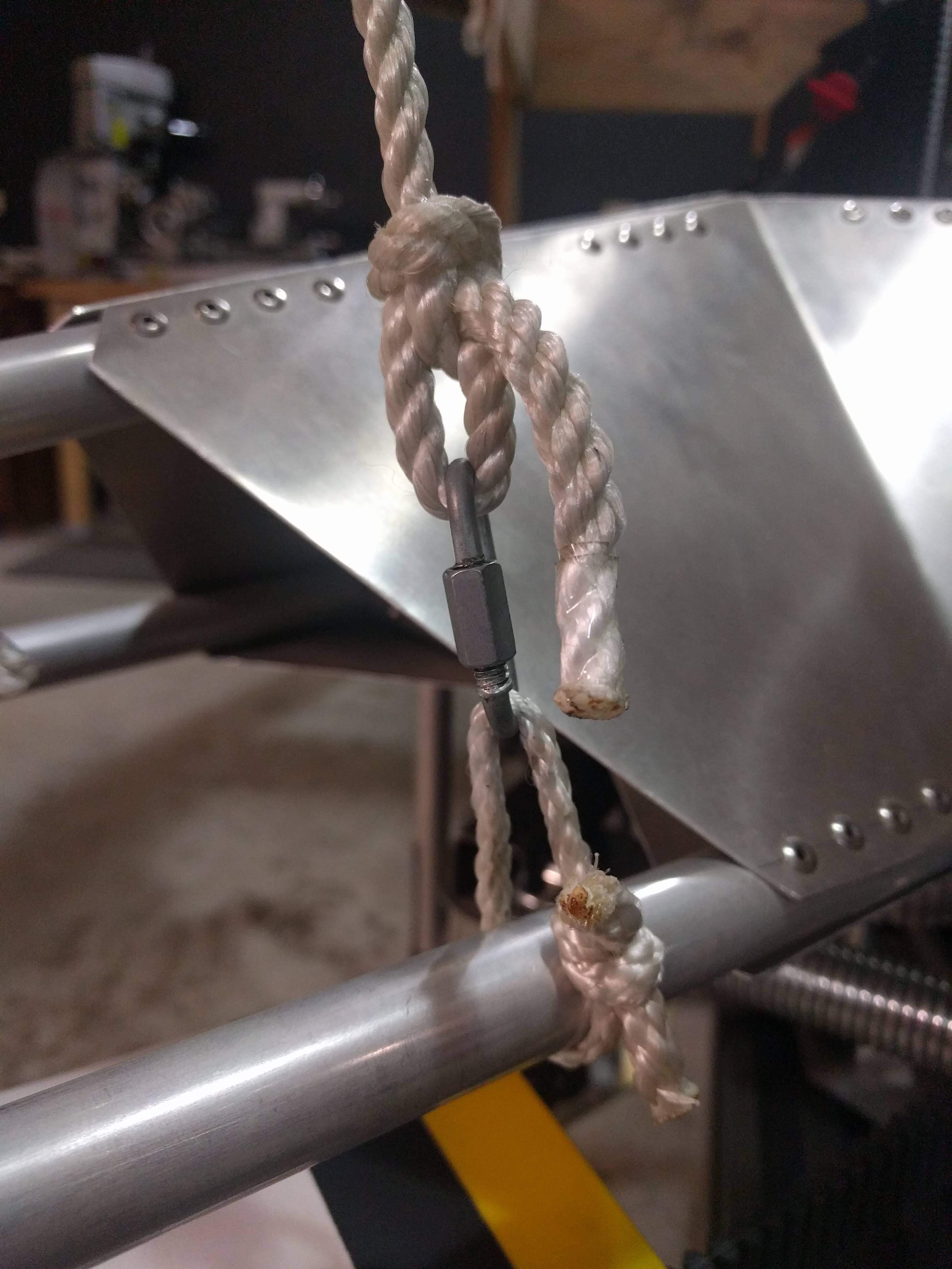
11/02/2018 at 21:28 • 0 commentsWith a full set of #EVPR: Electric Variable Pitch Rotors completed, the next round of testing is getting close. One item on the to-do list to get ready is having dedicated vehicle mounts. In the past the vehicle was suspended by a loop of rope around the structural frame. Below is the previous setup.
![]()
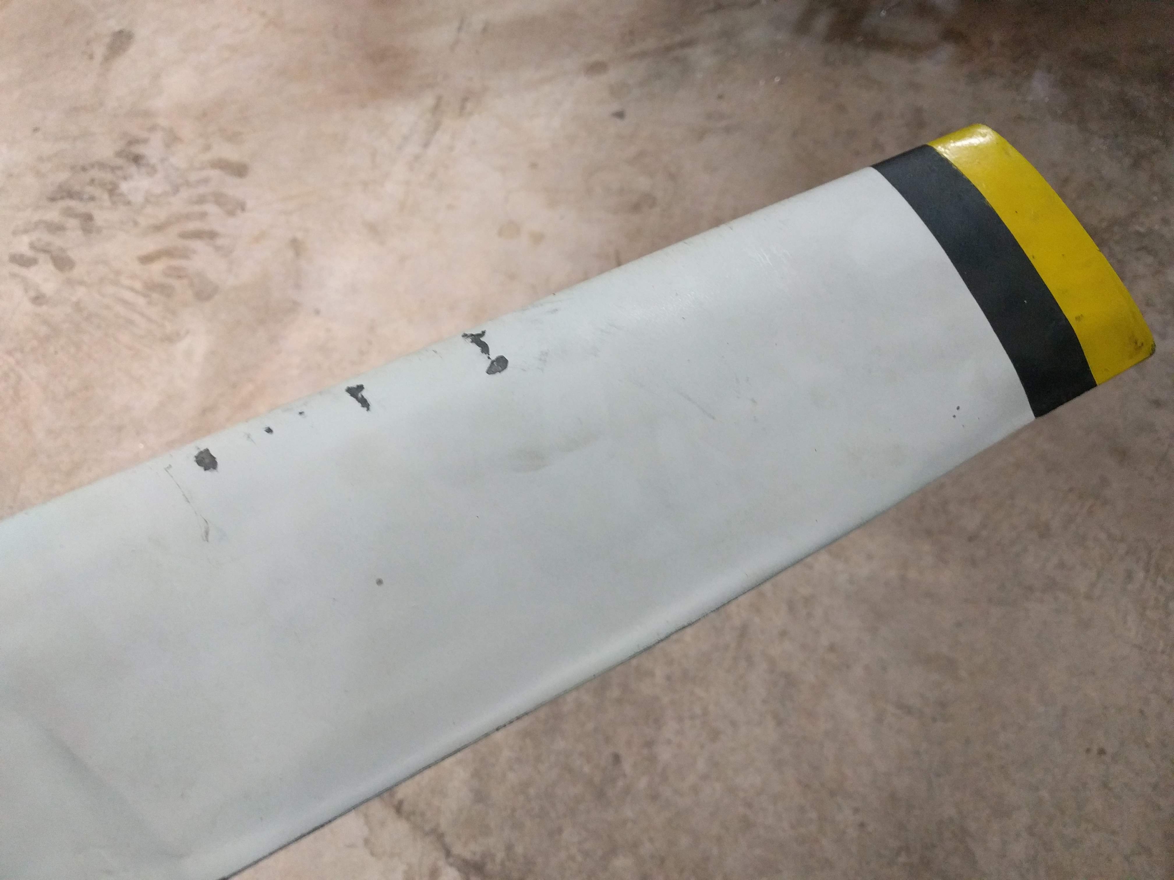
The issues is that the loops tend to move around, and when the ropes go slack, the rope ends can hit the rotors.
![]()
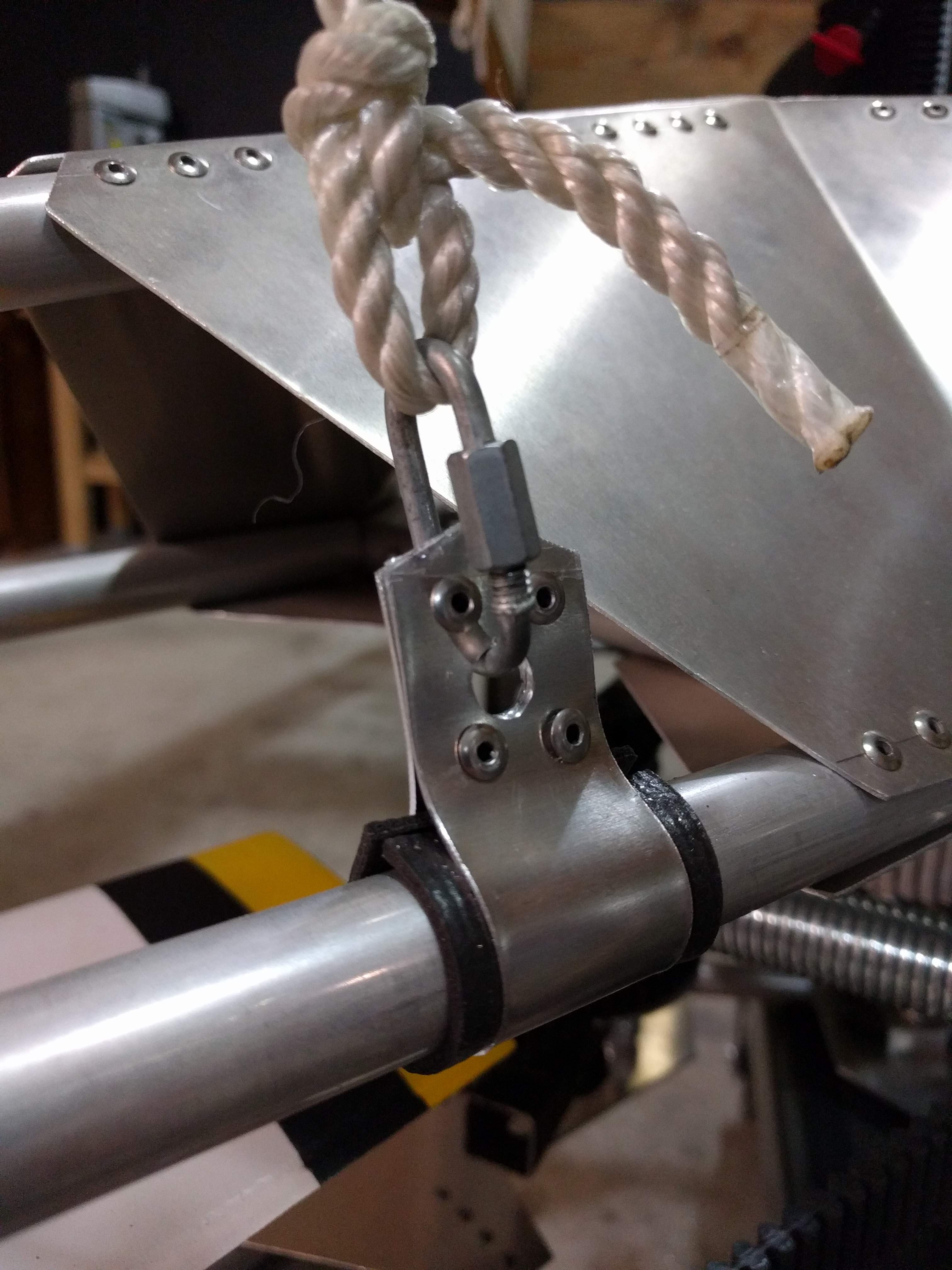
With a brand new set of rotors, it'd be nice to keep them in good condition. So dedicated vehicle mounts were added.
![]()
The mount is 1" wide and is the same thickness used on the gussets. The black material is a non-slip drawer liner material, to keep the parts from chafing. No more movement of the mounts and no more impact issues with the rotors.
-
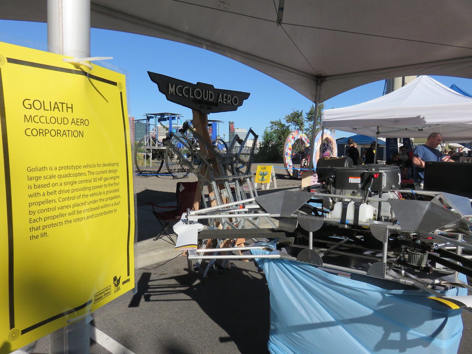
Portland Maker Faire Sept 15th and 16th
09/01/2018 at 18:07 • 0 commentsGoliath will be on display at the Portland Maker Faire at OMSI on Sept. 15th and 16th. The vehicle has a full set of #EVPR: Electric Variable Pitch Rotor installed. In addition to the Mk. II vehicle, we'll also have the Mk. I frame on display.
![]()
-
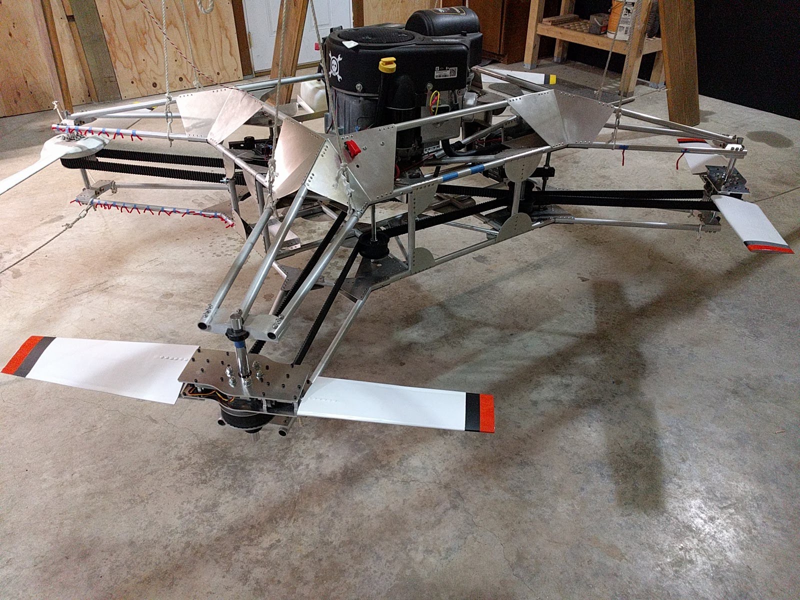
OMSI Robot Weekend June 16th and 17th
06/01/2018 at 20:00 • 0 commentsIn the Pacific Northwest and want to see Goliath Mk. II or the #EVPR: Electric Variable Pitch Rotor in person? Come out to OMSI's Robot Weekend on June 16th and 17th. This will be the first time Goliath is displayed with all of the controls integrated into the vehicle. The last of the variable pitch rotors has been assembled and is ready to go on the vehicle.
Below is a photo with the first two variable pitch rotors mounted.
![]()
-
Flight Controller Died, Looking For a New Controller...
06/23/2017 at 03:58 • 5 commentsProgress is being made the flight controls and the hub for the first prototype was attached to Goliath and spun up to make sure it held together (see #EVPR: Electric Variable Pitch Rotor for more details). There were no issues with the EVPR, there was an issue with the flight controller. When the vehicle was activated, the controller didn't power up properly. The Pixhawk consists on an FMU and an IO board. The IO board power was the only light coming on, nothing else. As a work around for this test, the flight controller was removed and I went back to controller the throttle with just a standard RC receiver directly connected.
While I can do a little bit more testing without the controller, it's not going to be too long before I need a new controller to start testing the interface between it and the EVPR. However, I'm a little hesitant to get another Pixhawk as I'm not sure what went wrong with the old one. It was about 3 years old, but there was only a handful of hours on it. There were a few rough tests, before I nailed down the isolation on the avionics tray and Goliath had two solenoids go bad, most likely due to vibration.
I'm familiar with the PX4 flight stack and at least know conceptually how to proceed with modifying the software to work with the EVPR. However there a few controllers that use the PX4 stack including the newer Pixhawk 2.1. Of course it uses different connectors, so the stack of DF13 connectors I have laying around as well as the GPS would be worthless, but maybe it makes sense to upgrade.
If anyone has any thoughts I'd love to hear them.
-
Control Hardware Starting to Take Shape
03/27/2017 at 02:42 • 0 commentsUp till now the work on Goliath has concentrated the drive train and the structure. The controls were put on the back burner until the other design problems were addressed. The other items aren't done, but the project has progressed to the point that having a control system would be helpful.
When Goliath was originally conceived three years ago, the default control scheme was to use vanes underneath the rotors to direct the airflow for control. This was chosen because it was the simplest hardware setup to implement and it's been demonstrated to work for hovercraft. Back in October I started doing some basic calculations to size the control vanes and determine the required servo sizes. Turns out assuming that if it works for a hovercraft, it'll work for Goliath was a bad assumption.
The issue with using vanes is the rotor downwash velocity. Goliath has a similar amount of horsepower as a hovercraft, but instead of 1 fan, there are 4 rotors, so the power per area is reduced by a factor of 4. Additionally the equation for the force generated by a vane is:
So if the downwash is reduced by a factor of 2, the force created by the vane is decreased by a factor of four. The end result is that at full thrust, a single vane would have generated only two pounds of force. Which would be grossly inadequate. More force can be generated using multiple vanes in parallel, but the forces would still be low.
I was discussing this issue with @Benchoff at the OSHW summit, and he suggested using grid fins instead. Doing some back of the envelope calculations show that grid fins should generate enough force. The downside is that the the grid fins have much higher drag, which would reduce the payload or flight time.
Ignoring their complexity, variable pitch rotors would be the ideal control scheme. Variable pitch rotors would be able to generate larger moment torques than either vanes or grid fins. However, the increased complexity and the fact that Goliath is already a complex project, convinced me not to pursue this.
However, it's been three years and I really want to see Goliath fly, so I've decided to start building both grid fins and a variable pitch rotor. If I pick one scheme and it doesn't work, then it'll be that much longer before it can fly. So I'll incrementally develop both and see which one works out better.
Grid Fins
The grid fins I'll document as part of Goliath as they are relatively straight forward. I have sourced some material to create the fins. The fins will be made from aluminum louvers for florescent lighting. It was difficult finding sheets big enough to make a 36" disc from, but I finally found some 4'x4' sheets (shown below).
![]() The next step will be cutting out a test disc and placing it under a rotor to determine the control forces generated.
The next step will be cutting out a test disc and placing it under a rotor to determine the control forces generated.Variable Pitch Rotors
The variable pitch rotors are a different story. I had decided not to pursue this until I came across some research that made me realize that it may be possible to create an electrically actuated variable pitch rotor with the servos contained inside the rotor hub.
I've created a separate project, #EVPR: Electric Variable Pitch Rotor, and I'll be documenting the progress there. I'll be populating more of the design details there, be sure to follow the project if you're interested and want to get updates. Additionally, I think that the project can be useful for other multi-rotors and even conventional aircraft, so I'm entering #EVPR: Electric Variable Pitch Rotor in the 2017 Hackaday Prize. If you think it's worthwhile, but sure to give it a like.
-
Evaluating Aerodynamics
03/12/2017 at 00:26 • 0 commentsGoliath hovered for the first time in September of 2016. The hover performance was less than desirable since it required a higher throttle setting than hoped and the vehicle did not rise evenly. It tended to favor the port side or the aft. Even more puzzling, was that it tended to lift off first on the side that had the most weight. Ballast could fix the issue, but understanding why is also important. Testing has continued to evaluate the aerodynamics of the setup. Below is a video compilation of some of those tests.
Test 12 was a simple flow visualization of the rotor downwash. Tufts of yarn were added to the frame to show the flow direction along the radius of the rotor and into the frame. The tufts behaved as expected, with the tufts under the rotor mostly steady. Inside the frame, the tufts indicated the flow reversed and flowed upward due to ground effects. While the tufts wiggled, there did not appear to be anything that suggested any unsteady flow phenomena.
Tests were also conducted outside to see if the shop walls and ceiling were effecting the aerodynamics. Occasionally in the past, loose debris had been ingested into the rotors and the debris recirculated inside the wake as the flow got turned around by the walls and got re-ingested. Testing outside reduced the re-circulation.
Test 16 nearly ended up with the vehicle getting damaged. There were four hold-downs, intended to allow the vehicle to move slightly upward, yet remain captive. They weren't made long enough and the hold-downs failed on the aft end of the vehicle. Fortunately, the throttle was reduced in time and the vehicle settled back on the stand (albeit precariously).
The hold-downs were fixed and the testing continued. During Test 17, the vehicle again lifted up, favoring the port side, but at a reduced throttle setting. However, the test stand didn't allow enough movement for a full hover to be achieved. The test showed that the asymmetries were present, regardless.
In theory, the rotors themselves should have been out of ground effect as they were at least one diameter above the ground. However, for quadcopters, it may be that the ground effect is dependent on the length scale of the four rotors together and not the length scale of a single rotor. If that is true, then perhaps the port rotors are experiencing higher thrust since they are slightly closer to the ground. It's difficult to tell exactly. This may be why the Mallory Hoverbike has the offset rotors catty-corner from each other.
-
Mitigating the vibrations
12/12/2016 at 05:04 • 0 commentsI'd hoped to be well into working on the controls on Goliath by now, but the shorter days and colder weather mean less time in the shop. I'm still nailing down some lingering issues with the drive train. The new pulleys are weeping grease because the bearings are getting too hot. I suspect it's because I'm using all thread axles and nuts to keep the bearings in place. I'm working on building the proper axles and axles mounts to go with the new pulleys.
![]() Meanwhile I wanted to document the progress made on mitigating the vibrations that the avionics experience. This was accomplished by better isolating the engine from the frame and the avionics tray from the frame. The new engine mounts are made primarily of rubber, but are built such that if the rubber fails, the bolts are still captive. Stainless steel bolts are used to attach the mounts.
Meanwhile I wanted to document the progress made on mitigating the vibrations that the avionics experience. This was accomplished by better isolating the engine from the frame and the avionics tray from the frame. The new engine mounts are made primarily of rubber, but are built such that if the rubber fails, the bolts are still captive. Stainless steel bolts are used to attach the mounts.![]() The avionics tray was switched from aluminum to steel. This was to add mass to help reduce the displacement of the avionics tray. Below is the new tray with some of the avionics populated.
The avionics tray was switched from aluminum to steel. This was to add mass to help reduce the displacement of the avionics tray. Below is the new tray with some of the avionics populated.![]() The tray is mounted to the frame using four Expansion Nuts. I forgot to take a picture of them before I installed them, so here is a link. Below is a shot showing the flange on the expansion nut between the tray and the frame.
The tray is mounted to the frame using four Expansion Nuts. I forgot to take a picture of them before I installed them, so here is a link. Below is a shot showing the flange on the expansion nut between the tray and the frame.![]() So how much did all the changes help? Data from the Pixhawk shows a huge reduction in the pitch rates down by a factor of 5 to 10. This means that the Pixhawk should be able to control Goliath once the rest of the hardware is complete.
So how much did all the changes help? Data from the Pixhawk shows a huge reduction in the pitch rates down by a factor of 5 to 10. This means that the Pixhawk should be able to control Goliath once the rest of the hardware is complete. ![]() Hopefully the next log update in the not too distant future will be about fixing the bearing issues.
Hopefully the next log update in the not too distant future will be about fixing the bearing issues.
 The next step will be cutting out a test disc and placing it under a rotor to determine the control forces generated.
 Meanwhile I wanted to document the progress made on mitigating the vibrations that the avionics experience. This was accomplished by better isolating the engine from the frame and the avionics tray from the frame. The new engine mounts are made primarily of rubber, but are built such that if the rubber fails, the bolts are still captive. Stainless steel bolts are used to attach the mounts.
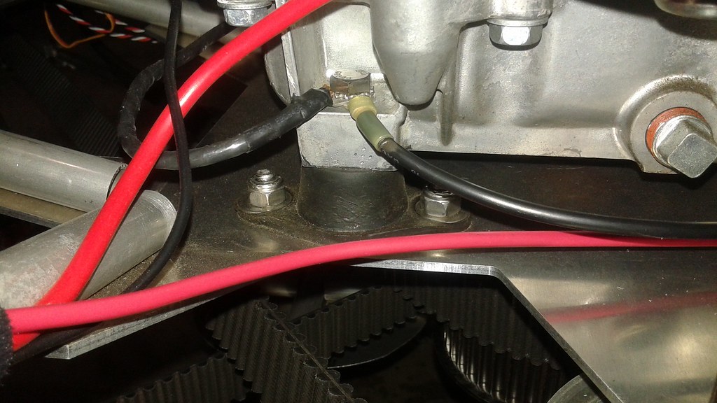 The avionics tray was switched from aluminum to steel. This was to add mass to help reduce the displacement of the avionics tray. Below is the new tray with some of the avionics populated.
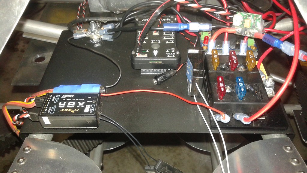 The tray is mounted to the frame using four Expansion Nuts. I forgot to take a picture of them before I installed them, so here is a
 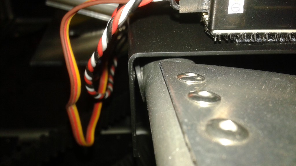 So how much did all the changes help? Data from the Pixhawk shows a huge reduction in the pitch rates down by a factor of 5 to 10. This means that the Pixhawk should be able to control Goliath once the rest of the hardware is complete.
 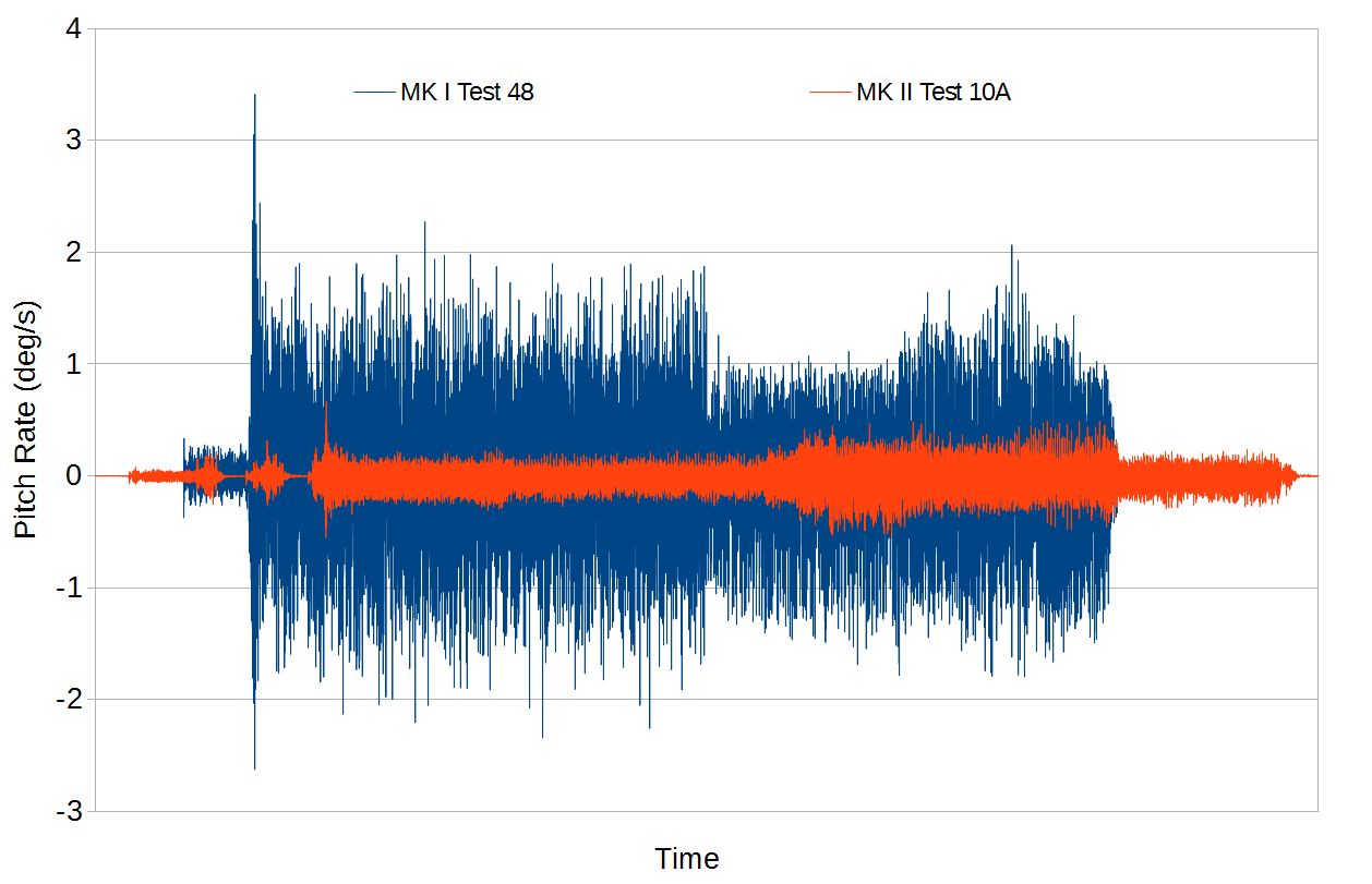 Hopefully the next log update in the not too distant future will be about fixing the bearing issues.