Peter McCloud
-
Quick Status Update
11/21/2016 at 05:25 • 0 commentsIt's been a little over two months since Goliath hovered for the first time. Here are some of things that have gone on since then.
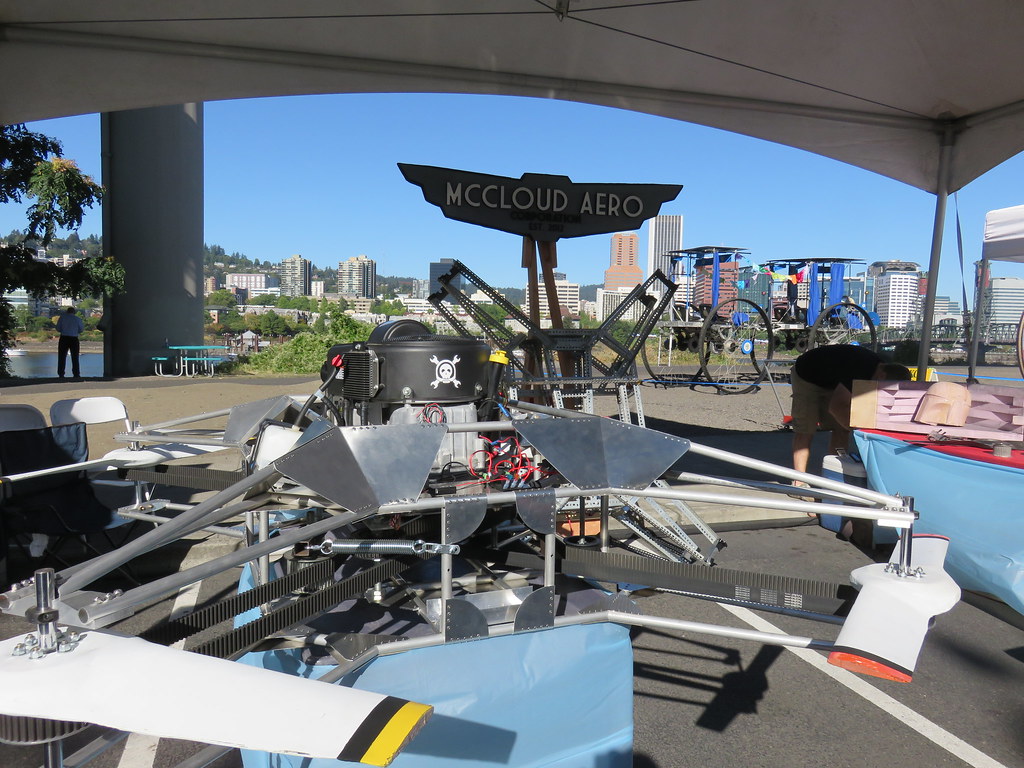
First was a trip to the Portland Maker Faire, September 11 and 12th at OMSI. It was a lot of fun showing off the vehicle, especially now that it hovers. Thanks to everyone who came out and checked out the project. I had a lot of great conversations that weekend.
![]()
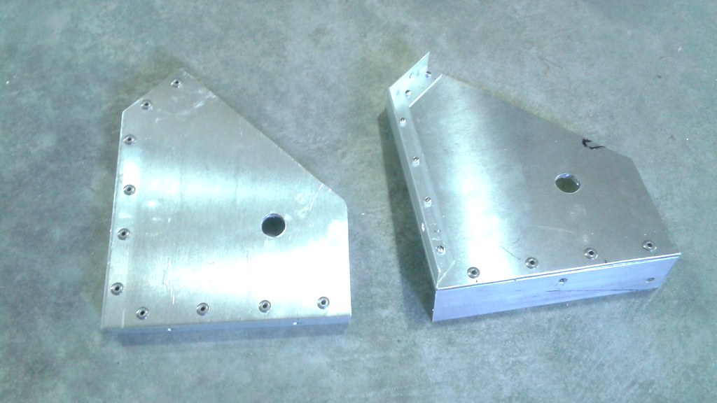
![]() After getting back to the shop and making sure everything was in working order, it was time to get back to work. The first order of business was to finalize some of the hardware. While Goliath hovered, the center of gravity didn't seem to be in the most ideal location. In order to remedy this, all of the hardware needs to be finalized with the flight weight components, particularly the remaining steel pulleys.
After getting back to the shop and making sure everything was in working order, it was time to get back to work. The first order of business was to finalize some of the hardware. While Goliath hovered, the center of gravity didn't seem to be in the most ideal location. In order to remedy this, all of the hardware needs to be finalized with the flight weight components, particularly the remaining steel pulleys.This was the same process as before, but since these are idlers and tensioners, no holes are needed for bolts. The last of of these components are complete, with each saving around a pound of weight. There is now only one one steel pulley left on the vehicle, the main engine pulley.
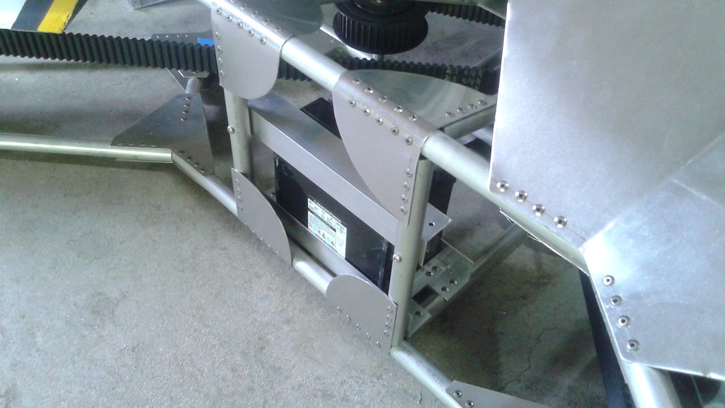
![]() There was also a hiccup with the battery and solenoid. The battery died, likely because it was undersized and was being deeply discharged. A new bigger battery was added with 18Ah, 80% more capacity than the previous battery, but with only 4 more lbs. Some thought was given to switching from the lead AGM type to a Lithium based battery, which would save about 10 lbs. However, the AGM has been demonstrated to work with the high vibration environments.
There was also a hiccup with the battery and solenoid. The battery died, likely because it was undersized and was being deeply discharged. A new bigger battery was added with 18Ah, 80% more capacity than the previous battery, but with only 4 more lbs. Some thought was given to switching from the lead AGM type to a Lithium based battery, which would save about 10 lbs. However, the AGM has been demonstrated to work with the high vibration environments.The solenoid failed again, the second on that's failed on Goliath. It's obvious that the stock lawnmower ones aren't built for the vibrations that Goliath creates. It was replaced with another stock solenoid as a temporary fix, but a heavy duty one needs to be sourced for the future.
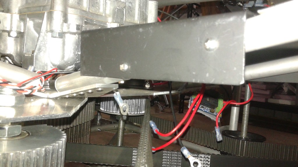
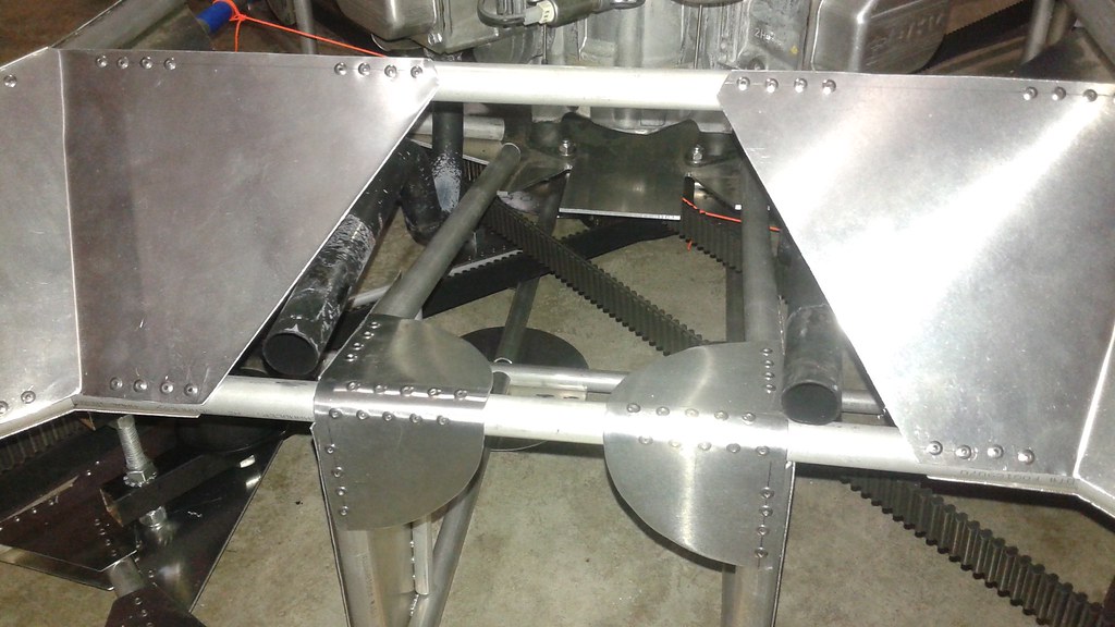
Lastly, the temporary Avionics Tray was replaced with a permanent one. This time it was made from 16 gauge steel. It weighs a little more than a pound. The idea is that the added mass will help to dampen the vibrations. The tray is isolated from the frame. using rubber expansion nuts.
![]()
![]() I'll have more details in a future log post, but the great news is that between the new engine mounts and the avionics tray have reduced the vibrations that the Pixhawk experiences low enough for it to work now.
I'll have more details in a future log post, but the great news is that between the new engine mounts and the avionics tray have reduced the vibrations that the Pixhawk experiences low enough for it to work now.Stay tuned for more details.
-
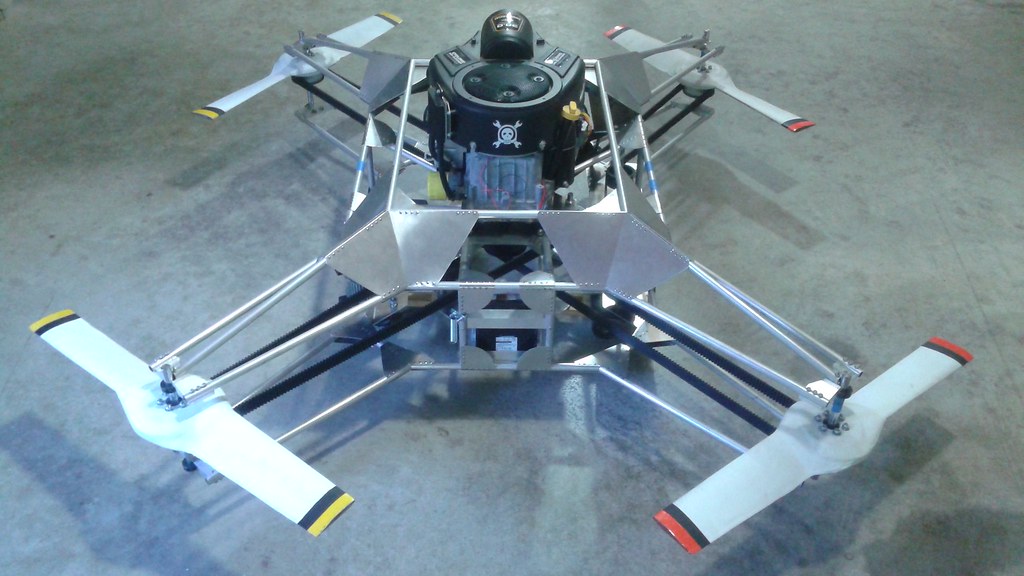
Goliath Mk. II Hovers!
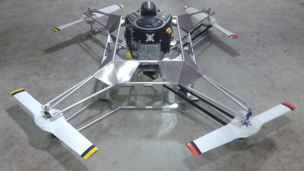
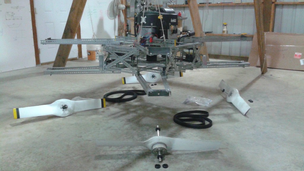
09/08/2016 at 05:21 • 8 commentsOver Labor Day weekend the assembly of the Mk. II vehicle was completed. The new vehicle was weighed and the current weight is 170 lbs, 50 lbs lighter than the previous vehicle. The first couple of tests were conducted and Goliath has hovered for the first time!
There is obviously a lot more to be done, but hovering is a big step in the right direction.
Also, if you're in the Portland area this weekend, come see Goliath at the Maker Faire!
![]()
-
Assembly Nearly Complete, 1 Week to the Portland Maker Faire
09/03/2016 at 20:44 • 0 commentsWork has continued on the Mk II vehicle and it's nearly complete. The latest work has been attaching the idler pulleys, tensioners and the battery.
![]()
The ilder pulleys were mounted to same 1/8" plate used for the engine mounting plate. Aluminum angle was riveted around the edges and the plates were bolted to the frame.
![]() Below, the two idler pulleys for the single sided belt are attached.
Below, the two idler pulleys for the single sided belt are attached.![]() The center idler for the double sided belt required a different approach. The upper attachment was already part of the engine mounting plate. The lower attachment was made from a smaller piece of plate and riveted to two cross members that were added to the frame. Below is a shot looking at the underside of the frame where the cross members were added.
The center idler for the double sided belt required a different approach. The upper attachment was already part of the engine mounting plate. The lower attachment was made from a smaller piece of plate and riveted to two cross members that were added to the frame. Below is a shot looking at the underside of the frame where the cross members were added. ![]() The other idler for the double sided belt was attached using two different methods. On the lower side, the aluminum plate with angle was used and bolted to the frame. For the upper side just a plate was used was bolted to the engine mounting plate, using the same bolts for the engine mount.
The other idler for the double sided belt was attached using two different methods. On the lower side, the aluminum plate with angle was used and bolted to the frame. For the upper side just a plate was used was bolted to the engine mounting plate, using the same bolts for the engine mount.![]() With the idler pulleys all attached and the tensioner attachment method decided upon, some additional gussets were added to reinforce the aft end of the vehicle.
With the idler pulleys all attached and the tensioner attachment method decided upon, some additional gussets were added to reinforce the aft end of the vehicle.![]()
With the aft gussets attached, the exhaust pipes could mounted.![]() Not shown are the flexible mounts scavenged from the original frame.
Not shown are the flexible mounts scavenged from the original frame.Next a tray for the battery was created from angle pieces.
![]() A rubber liner was added to the bottom of the tray.
A rubber liner was added to the bottom of the tray.![]()
To keep the battery in place an additional piece of angle was bolted in place on top of the battery.
![]() Now all that remains to complete the Mk. II vehicle is to add to the electronics and the fuel tank. With some luck, the vehicle could be complete and running by Labor Day.
Now all that remains to complete the Mk. II vehicle is to add to the electronics and the fuel tank. With some luck, the vehicle could be complete and running by Labor Day.Stay tuned...
-
Come see Goliath Mk. II at the Portland Mini Maker Faire (Sept 10th and 11th)
08/25/2016 at 23:23 • 0 comments![]()
Goliath Mk. II will be at the Portland Mini Maker Faire on Saturday and Sunday, September 10th and 11th at OMSI. This will be the first time the Mk. II vehicle will be shown in public. I'm working on completing the vehicle and having its first test before the Maker Faire. The vehicle will not be run at the Faire. Look for it at the McCloud Aero Corp booth.
![]() More details can be found at:
More details can be found at: -
Lower Frame Completed, Upper and Lower Halves Joined
08/15/2016 at 04:26 • 0 commentsThis last weekend was productive and the major portions of the frame are now complete.
![]() After attaching the engine mounting plate to the frame, the next step was assembling the lower frame. The lower frame is similar to the lower ring of the upper frame, so it was possible to reuse the jig for the upper frame with some minor modifications. This was simply making new wood rotor shaft mounts for the lower frame and swapping them out in place of the old ones. Then all of the lower frame elements were cut and placed in the jig.
After attaching the engine mounting plate to the frame, the next step was assembling the lower frame. The lower frame is similar to the lower ring of the upper frame, so it was possible to reuse the jig for the upper frame with some minor modifications. This was simply making new wood rotor shaft mounts for the lower frame and swapping them out in place of the old ones. Then all of the lower frame elements were cut and placed in the jig.![]() With all of the elements in place, the same process for riveting the gussets was followed.
With all of the elements in place, the same process for riveting the gussets was followed.![]()
Next the lower rotor shaft mounts were machined out of metal. There was a couple of hiccups due to the double sided tape not holding and bit breaking.
![]() Once the mounts were completed, the shaft mounts were attached with bolts to the lower frame in the same manner of the upper frame.
Once the mounts were completed, the shaft mounts were attached with bolts to the lower frame in the same manner of the upper frame.![]() In the future the gussets would be attached to the top side of the lower frame. However, at this stage the method of attaching the idler pulleys and tensioners hadn't been finalized. Therefore the upper gussets were left off at this point.
In the future the gussets would be attached to the top side of the lower frame. However, at this stage the method of attaching the idler pulleys and tensioners hadn't been finalized. Therefore the upper gussets were left off at this point.With the two halves completed, it was time to start attaching them together. Both halves of the frame were attached to the rotor axles to hold the two halves relative to each other. It was easiest to work with the frame flipped over since most of the riveting was on the bottom.
![]() Four lengths of tubing were initially cut and attached on the sides of the frame along with the gussets for the lower frame. Clecos were used to hold the parts together prior to riveting.
Four lengths of tubing were initially cut and attached on the sides of the frame along with the gussets for the lower frame. Clecos were used to hold the parts together prior to riveting.![]() Next the lower cross members were added to the lower frame
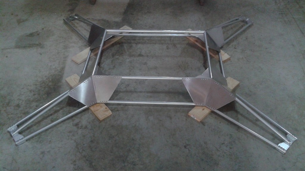
Next the lower cross members were added to the lower frame![]() With all of the new elements attached, it was time to riveting the parts and finalized the attachment between the frames. At that point the frame was flipped back over to see the progress.
With all of the new elements attached, it was time to riveting the parts and finalized the attachment between the frames. At that point the frame was flipped back over to see the progress.![]() At this point about 80% of the frame is complete. the frame members at the front of back need to be added and some smaller cross members need to be added to stiffen the frame. However, before completing the frame elements, the attachment hardware needs to be completed to make sure there aren't any issues with the remaining structure. Once the attachment hardware has been finalized, then the frame can be finalized.
At this point about 80% of the frame is complete. the frame members at the front of back need to be added and some smaller cross members need to be added to stiffen the frame. However, before completing the frame elements, the attachment hardware needs to be completed to make sure there aren't any issues with the remaining structure. Once the attachment hardware has been finalized, then the frame can be finalized. -
Attaching the Engine Mounting Plate to the Upper Frame
08/02/2016 at 19:32 • 1 commentProgress on the Mk. II vehicle is moving along and the engine mounting plate is now attached to the upper frame.
![]() The first step was to start measuring and cutting the tubing that attach the engine mounting plate to the upper frame. This was starting by making a simple jig to hold the pieces at the right elevation to each other.
The first step was to start measuring and cutting the tubing that attach the engine mounting plate to the upper frame. This was starting by making a simple jig to hold the pieces at the right elevation to each other. ![]() This worked for doing some preliminary alignment, but to make sure everything fit well, it was decided to redo the jig so that the engine could be placed on the vehicle while it was in the jig. This was done by further elevate all the pieces, with 2x4 blocks holding up the engine mounting plate.
This worked for doing some preliminary alignment, but to make sure everything fit well, it was decided to redo the jig so that the engine could be placed on the vehicle while it was in the jig. This was done by further elevate all the pieces, with 2x4 blocks holding up the engine mounting plate.![]() When all of the tubing was cut, the holes were drilled on the ends attached to the mounting plate and the parts were held together with Clecos.
When all of the tubing was cut, the holes were drilled on the ends attached to the mounting plate and the parts were held together with Clecos.![]() The plate with the tubes attached was put back in the jig and aligned with the upper frame. Then the gussets for the remaining joints were made and attached with more Clecos.
The plate with the tubes attached was put back in the jig and aligned with the upper frame. Then the gussets for the remaining joints were made and attached with more Clecos.![]() The gussets are wrapped around the tubing and will also serve as the attachment points between the upper and lower halves of the frame. This required bending the gussets with a larger 3/4" radius. To get a good radius bend, the press brake was used with a 3/4" diameter steel bar placed along side the sheet metal to provide the right shape for bending.
The gussets are wrapped around the tubing and will also serve as the attachment points between the upper and lower halves of the frame. This required bending the gussets with a larger 3/4" radius. To get a good radius bend, the press brake was used with a 3/4" diameter steel bar placed along side the sheet metal to provide the right shape for bending.![]() Once all the gussets were in place, the engine was mounted to double check that there was adequate clearance, before permanently attaching the plate to the frame.
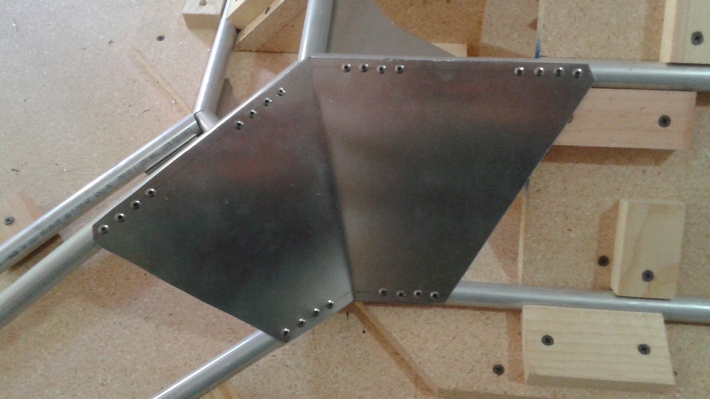
Once all the gussets were in place, the engine was mounted to double check that there was adequate clearance, before permanently attaching the plate to the frame.![]() All of the clearances checked out and with no glaring design issues present, the rest of the rivets were pulled on the frame side of the tubes. Since there wasn't enough clearance to pull the rivets under the engine mounting plate, the frame was flipped over and the last of the rivets in the plate were installed.
All of the clearances checked out and with no glaring design issues present, the rest of the rivets were pulled on the frame side of the tubes. Since there wasn't enough clearance to pull the rivets under the engine mounting plate, the frame was flipped over and the last of the rivets in the plate were installed.![]() A quick note on the rivets for the engine plate. Rivets are designed to join a specific thickness of material. The 1/8" thick plate is thicker than the gussets, so slightly longer rivets had to be used. So care has to be taken to make sure the right rivets are used in the different locations.
A quick note on the rivets for the engine plate. Rivets are designed to join a specific thickness of material. The 1/8" thick plate is thicker than the gussets, so slightly longer rivets had to be used. So care has to be taken to make sure the right rivets are used in the different locations.At this point, the frame is about 50% complete. The frame was weighed in it's current configuration (without the engine) and weighs 14 lbs, 2 oz. This means that the final structure weight is sill on track to weigh around 30 lbs.
Next up for the Mk. II vehicle is to build the lower half of the frame and machine the lower rotor shaft mounts. Once that work is complete, the two halves of the frames can be joined together.
![]()
-
Engine Mounting Plate Complete
07/26/2016 at 14:34 • 0 commentsThe engine mounting plate has been completed and the middle portion of the Mk. II frame is now complete.
![]()
Designing the engine mounting plate required working though a few iterations before the coming to current design. The plate is made from 1/8" thick 6061-T6 Al plate from Aircraft Spruce. It wasn't cheap, so making sure the design was good before cutting the material was important.
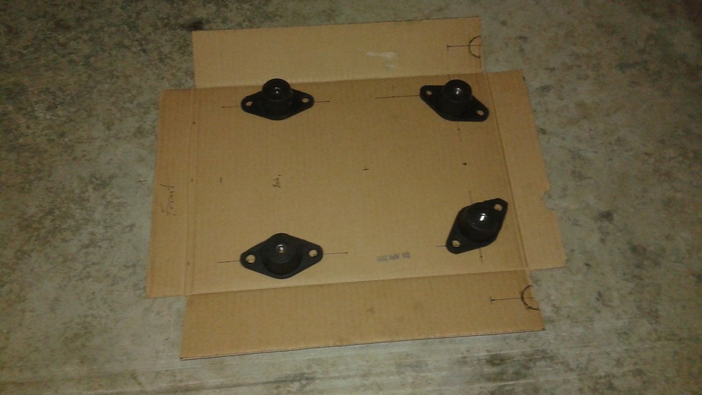
The first step was setting up the initial layout, using cardboard to layout the engine mounts and make sure that the plate wouldn't be in the way of the exhaust. The engine mounts are made of rubber and steel and should help with dampening some of the vibration from the engine.
![]()
After doing the cardboard layout, and comparing it to the Mk. I design, it became apparent that it would make sense to go ahead and incorporate the mount one of the idler pulleys as part of the design.
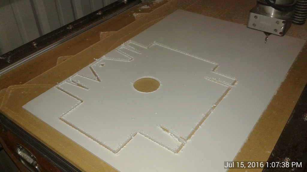
Next, the part was designed using CAD and another prototype was machined using foam board. One other feature incorporated. at this point was multiple tabs on the sides of the plate for attaching to both the lower and upper frames. The tabs would be bent +/- 15 degrees depending on which half of the frame it would be attached to.
![]() However, after holding the part inside the new frame a very big design flaw become apparent. The middle tabs were meant to be bent downwards, but that would place them in the way of the idler pulley, which will be placed below the engine plate. Second, I could go to both the lower and upper frame from the engine plate directly, otherwise the structure would have to pass through the belts. If that was done I'd have to assemble and re-assemble the frame every time the belts were added or removed.
However, after holding the part inside the new frame a very big design flaw become apparent. The middle tabs were meant to be bent downwards, but that would place them in the way of the idler pulley, which will be placed below the engine plate. Second, I could go to both the lower and upper frame from the engine plate directly, otherwise the structure would have to pass through the belts. If that was done I'd have to assemble and re-assemble the frame every time the belts were added or removed.It was decided to just attached the engine plate to the upper frame, similar to how the Mk I frame is laid out. The plate was redesigned. one last time, this time adding engine mounts to the front and back and also adding a mounting area for the motor servos at the aft end of the plate.
![]() After a test fit, the design was complete and the part was ready to be machined using the aluminum plate. Since the CNC router needs to go slow to cut the aluminum plate, it took about an hour to cut the part. In the images, the edges of the plate look somewhat rough. This is actually the protective film that is on both sides of the plate. The actual edges come out very clean.
After a test fit, the design was complete and the part was ready to be machined using the aluminum plate. Since the CNC router needs to go slow to cut the aluminum plate, it took about an hour to cut the part. In the images, the edges of the plate look somewhat rough. This is actually the protective film that is on both sides of the plate. The actual edges come out very clean.![]() After cutting, the tabs were bent to the correct angles using the press brake. The protective film has been left on to prevent marring the material.
After cutting, the tabs were bent to the correct angles using the press brake. The protective film has been left on to prevent marring the material.![]() After getting all of the bends to the right angle, the mounts were placed on the plate and the engine was test fit to make sure all of the clearances looked good.
After getting all of the bends to the right angle, the mounts were placed on the plate and the engine was test fit to make sure all of the clearances looked good.![]()
With the engine plate complete, it was time to start attaching it to the upper frame. I'll have those details in the next log.
-
New Rotor Shaft Mounts
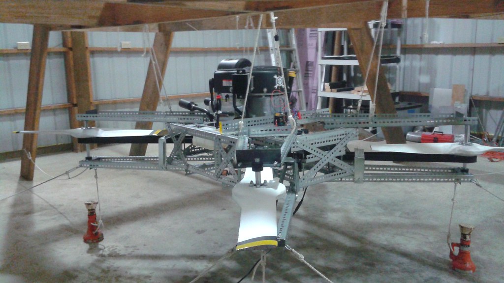
07/04/2016 at 03:10 • 6 commentsThe upper set of new engine mounts are now complete. This log documents both the design and the process of building the new mounts.
The new hardware is considerably different from the previous design. The prior mounts were originally a 6" piece of angle iron bolted to the slotted angle frame and had a slot cut out for the shaft. The shaft was held captive between two shaft collars that also served to transfer the thrust between the shaft and the shaft mounts. One of the previous shaft mounts can be seen below, just above the closest rotor.
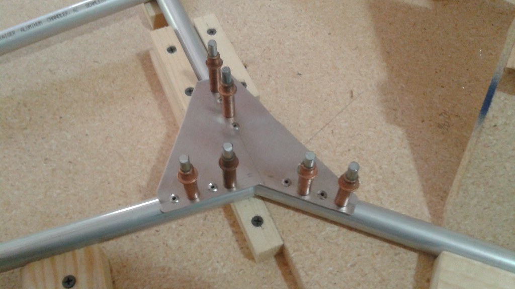
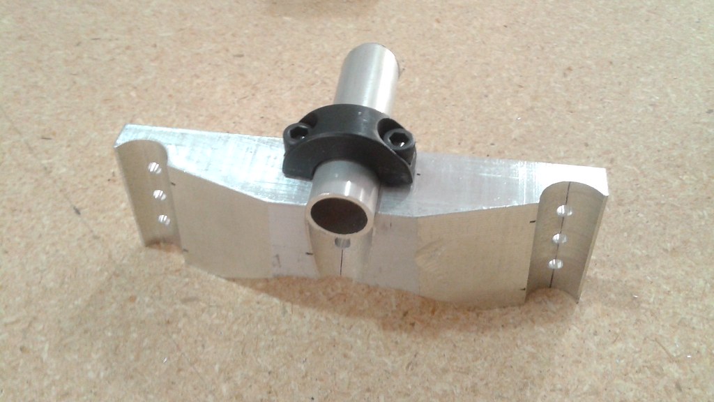
![]() The mounts for the Mk. II vehicle had to go from the shaft and mount to the three aluminum tubes that comprise the rotor arms. This required a custom part that could be bolted to the tubes and also act directly as the shaft mount, instead of using multiple shaft collars. The design process started by making a CAD object using Cubify Design.
The mounts for the Mk. II vehicle had to go from the shaft and mount to the three aluminum tubes that comprise the rotor arms. This required a custom part that could be bolted to the tubes and also act directly as the shaft mount, instead of using multiple shaft collars. The design process started by making a CAD object using Cubify Design.![]() After that, the next step was making some prototypes out of wood on the CNC router.
After that, the next step was making some prototypes out of wood on the CNC router.![]() These were also used in the Jig to align the tubes for the rotor arms.
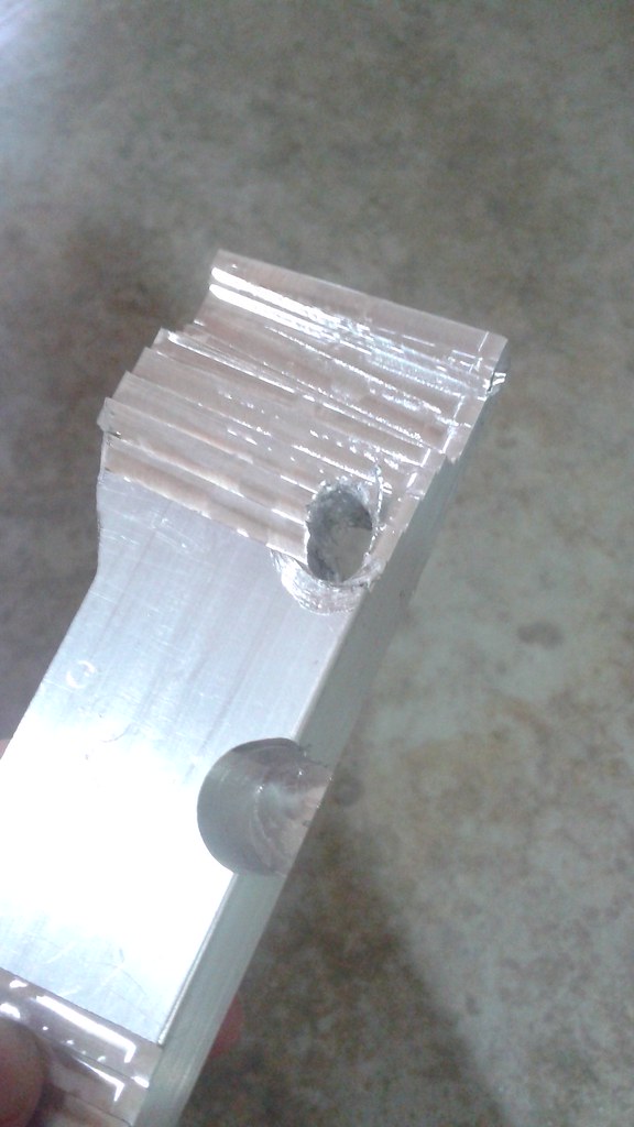
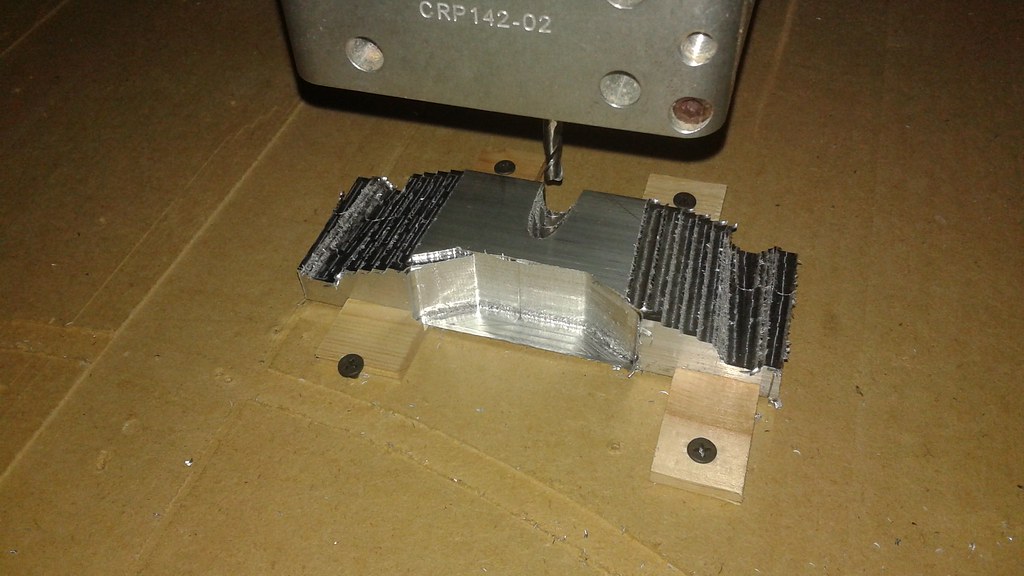
These were also used in the Jig to align the tubes for the rotor arms.Next, it was time to make the actual hardware. The parts were machined out of 6061-T6 bar stock. The parts were cut on the CNC router. A CNC mill would be better suited than the CNC router, but I don't have one. That being the case, it took a couple tests to find the right settings on the CNC router. The first test run had some issues with galling. The galling causes the poor surface finish and the feathering on the edges.
![]() The fix was simply to slow down the feed rates and lower the spindle speed. After that the roughing passes came out a lot cleaner.
The fix was simply to slow down the feed rates and lower the spindle speed. After that the roughing passes came out a lot cleaner.![]() Once the roughing pass was done, a waterline pass was made.
Once the roughing pass was done, a waterline pass was made.![]() Next, a parallel pass was made in the Y-axis to clean up the upper surface.
Next, a parallel pass was made in the Y-axis to clean up the upper surface.![]() The last pass was with a 3/4" diameter ball end to clean up the grooves.
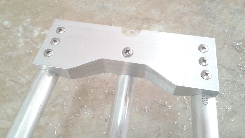
The last pass was with a 3/4" diameter ball end to clean up the grooves.![]() With the machining on the CNC Router done, the next step was to drill and countersink the holes for the bolts to mount to the frame.
With the machining on the CNC Router done, the next step was to drill and countersink the holes for the bolts to mount to the frame. ![]() The last step was to drill the holes for the mounting.
The last step was to drill the holes for the mounting.![]() When everything is together the shafts will be mounted using half of a shaft collar.
When everything is together the shafts will be mounted using half of a shaft collar.![]()
With the parts complete, it was time to attach them to the upper frame.
![]()
![]()
The next part of the project is building the engine supports. To make sure everything is right before it's riveted all together, which means that the parts need to be scavenged from the first vehicle. More on that next time.
![]()
-
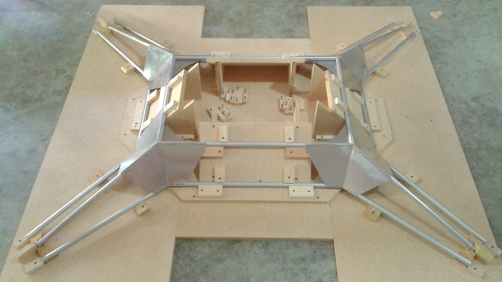
Upper Frame Assembled
06/25/2016 at 15:17 • 0 commentsThe process of building the Mk. II vehicle is going smoothly and the upper part of the frame is now complete.
![]() The build process has been documented in step 3 of the instructions, but here's a brief overview of the build process.
The build process has been documented in step 3 of the instructions, but here's a brief overview of the build process.After finalizing the structure design, it became clear that a jig was going to be needed to accurately align the pieces and do the actual assembly. It appeared too complex to build a single jig for the entire frame, so the frame was broken down into upper and lower pieces.
The jig for the upper frame was assembled out of two 4'x8' sheets of particle board. Not an ideal material for a jig, since it doesn't have the greatest dimensional stability, but it's in-expensive for building the large jig. Scrap wood was used for adding joints and for holding the frame elements in place. The frame elements were cut as the jig was being built, so the picture of the final assembled jig also shows the frame elements in place.
![]() With the jig complete and the frame pieces cut, the next step was to start designing the gussets. Typically templates were cut out of card stock and refined until the shape was correct.
With the jig complete and the frame pieces cut, the next step was to start designing the gussets. Typically templates were cut out of card stock and refined until the shape was correct.![]() The templates were then used to trace out the shape on the 0.040" thick sheet metal and cut out with either tin snips or a jigsaw depending on the shape.
The templates were then used to trace out the shape on the 0.040" thick sheet metal and cut out with either tin snips or a jigsaw depending on the shape.![]() At this point there was a detour into another side project. The angle gussets needed to be bent using a press brake. Several years ago I obtained one cheap off of Craigslist and began to tear it down to clean it off since it had rust and lots of flaking paint. I got half way done cleaning it and then forgot about it. Then all the parts got packed up and moved across the country and the parts scattered about. So in order to use it, I first had to find all the parts and then remember how it went back together. Luckily after a bit of searching all of the parts were found
At this point there was a detour into another side project. The angle gussets needed to be bent using a press brake. Several years ago I obtained one cheap off of Craigslist and began to tear it down to clean it off since it had rust and lots of flaking paint. I got half way done cleaning it and then forgot about it. Then all the parts got packed up and moved across the country and the parts scattered about. So in order to use it, I first had to find all the parts and then remember how it went back together. Luckily after a bit of searching all of the parts were found![]() And even more fortunately, I remembered how it went back together after 4 years.
And even more fortunately, I remembered how it went back together after 4 years.![]() After completing the side project. The angle gussets were able to be completed.
After completing the side project. The angle gussets were able to be completed.![]() With the gussets completed, it was a matter of assembling all the parts. To get the best alignment, Clecos are used to hold the parts in place while other holes are drilled. Clecos are spring loaded and a special pair of pliers are used to insert them and remove them. Every other hole gets a Cleco and then the remaining holes get riveted together.
With the gussets completed, it was a matter of assembling all the parts. To get the best alignment, Clecos are used to hold the parts in place while other holes are drilled. Clecos are spring loaded and a special pair of pliers are used to insert them and remove them. Every other hole gets a Cleco and then the remaining holes get riveted together.![]()
Finally the Clecos are removed and the remaining holes are filled with rivets.
![]()
Drill, rivet, repeat x300 and then the upper frame is complete:
![]() Again, the step by step process is documented in the instructions. The next steps are to build the lower frame and to machine the rotor shaft mounts. More on the rotor shaft mounts next time.
Again, the step by step process is documented in the instructions. The next steps are to build the lower frame and to machine the rotor shaft mounts. More on the rotor shaft mounts next time.![]()
-
Mk II Structure Design
06/15/2016 at 02:31 • 0 commentsWork o the Mk II vehicle is progressing. The last project log documented some of the generl changes for the Mk II vehicle. This log will cover the Mk II stucture design and explain some of the choices made.
Structures Types and Material Choices
The choice of structure type and material type aren't independent of each other. Different materials are better suited for different structure types. Therefore both need to be considered together.
A lot of experimental aircraft use a monocoque or semi-monocoque structure. Typically these types of structures are sheet aluminum or composites. Another common type of structure used is a truss frame that is then covered.
For the Mk II frame a truss structure design was chosen. One of the primary reasons was that analyzing a truss structure is more within my capabilities, especially with a software written specifically for truss analysis such as Frame3DD, an open source software package. There are other methods and software out there for analyzing other structure types, but the learning curve is a lot steeper.
With the stucture type chosen, the material type was next. Experimental aircraft with trusses are typically either built using 4130 steel or aluminum depending on the loads. Another material possibility is carbon fiber tubing. The decision to go with aluminum for the truss was influenced by looking at aircraft with similar total weights and similar engine weights. Aerodrome Aeroplanes is one example of one of those types of aircraft. The frame are very light weight (this build log has the builder holding the fuselage by himself) and the time/effort required to build them is less than other types of aircraft.
The specific type of aluminum chosen was 6061-T6. Alloys considered were basically ones that were easily available and have a reasonable amount of corrosion resistance.
Structure Analysis
As mentioned above, Frame3DD was used to the the analysis of the truss. The inputs consist of a text file containing a list of the node coordinates, a list of the frame elements and their properties, and the loads. The tutorials are fairly straight forward and the software can simply be run from the command line. Below is a simplified analysis of the Goliath Mk II structure.
![]() The light blue lines represent the truss with no loads. The blue lines represent the frame deflections under load with an exaggeration factor of 10x. Keep in mind that this is with no factor of safety, but the analysis suggests that the frame will see very small deflections. The primary reason is that that I chose the tubing size optimized on cost (just found the tubing with the lowest cost/foot ) and not by weight or stress.
The light blue lines represent the truss with no loads. The blue lines represent the frame deflections under load with an exaggeration factor of 10x. Keep in mind that this is with no factor of safety, but the analysis suggests that the frame will see very small deflections. The primary reason is that that I chose the tubing size optimized on cost (just found the tubing with the lowest cost/foot ) and not by weight or stress.Structure Joints
The remaining choice for the structure was how to join all of the frame elements. The primary options were welding the joints or using gussets and rivets. Welding would likely provide a lighter structure, but the high vibrations could cause cracking at the welds. It's also not something that most people have in their skill set. Riveting on the other hand handles vibration well and is something that can easily be picked up. Therefore the choice was made to go with aluminum gussets and stainless pop rivets for the joints. Again this is a technique that is used on lightweight experimental aircraft.
Weight Savings
So what does this all mean? A stiffer frame and significantly less weight compared to the Mk I vehicle. Because of all of the reconfiguration done on the Mk I vehicle, there wasn't a direct measurement of how much the frame weighed, but the total weight of the steel structure is probably around 50 lbs. Even though cost was a big driver in sizing the frame elements for the Mk II vehicle, the structure is estimated to weigh less than 30 lbs.
Meanwhile, back in the shop
There'll be more details in future project logs, but meanwhile back in the shop, the actual hardware is starting to come together. Today the first of many rivets were placed on the new structure.
![]()
 After getting back to the shop and making sure everything was in working order, it was time to get back to work. The first order of business was to finalize some of the hardware. While Goliath hovered, the center of gravity didn't seem to be in the most ideal location. In order to remedy this, all of the hardware needs to be finalized with the flight weight components, particularly the remaining steel pulleys.
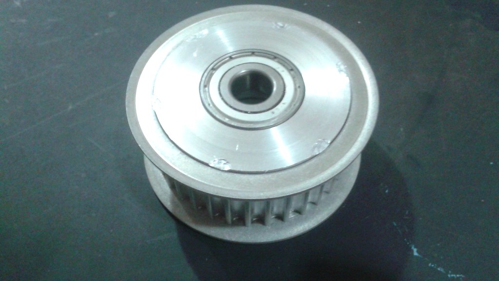 There was also a hiccup with the battery and solenoid. The battery died, likely because it was undersized and was being deeply discharged. A new bigger battery was added with 18Ah, 80% more capacity than the previous battery, but with only 4 more lbs. Some thought was given to switching from the lead AGM type to a Lithium based battery, which would save about 10 lbs. However, the AGM has been demonstrated to work with the high vibration environments.
 I'll have more details in a future log post, but the great news is that between the new engine mounts and the avionics tray have reduced the vibrations that the Pixhawk experiences low enough for it to work now.
 Below, the two idler pulleys for the single sided belt are attached.
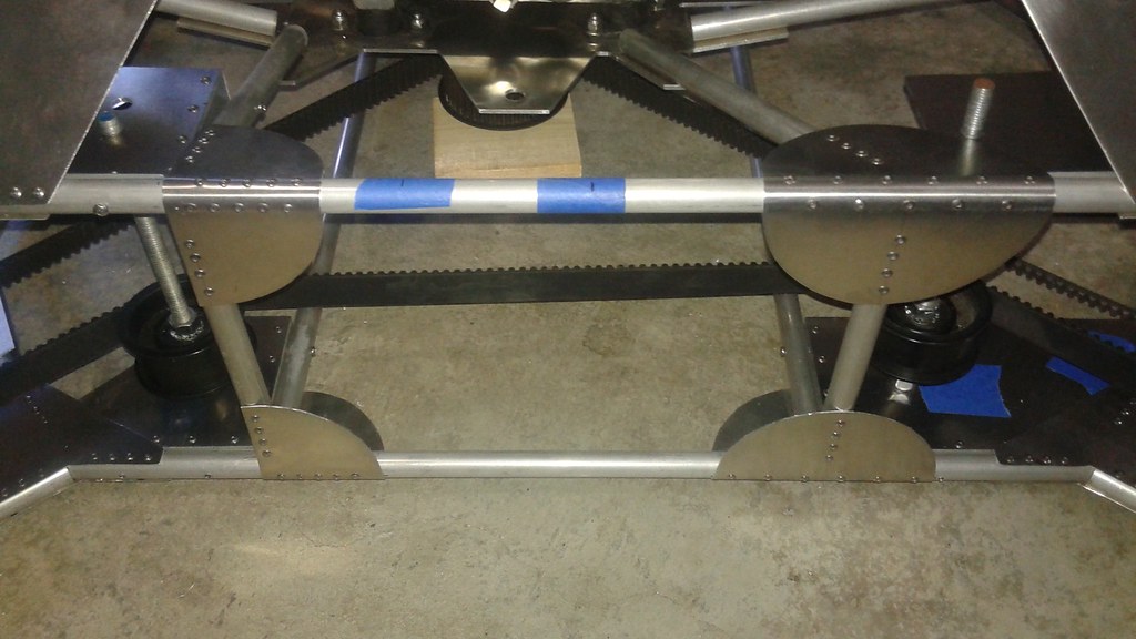 The center idler for the double sided belt required a different approach. The upper attachment was already part of the engine mounting plate. The lower attachment was made from a smaller piece of plate and riveted to two cross members that were added to the frame. Below is a shot looking at the underside of the frame where the cross members were added.
  The other idler for the double sided belt was attached using two different methods. On the lower side, the aluminum plate with angle was used and bolted to the frame. For the upper side just a plate was used was bolted to the engine mounting plate, using the same bolts for the engine mount.
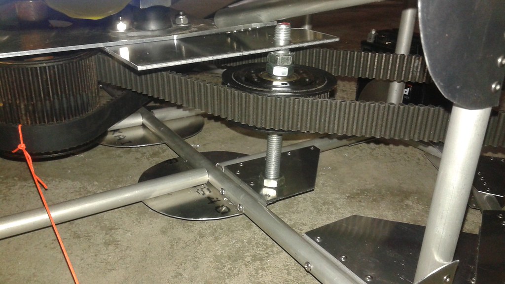 With the idler pulleys all attached and the tensioner attachment method decided upon, some additional gussets were added to reinforce the aft end of the vehicle.
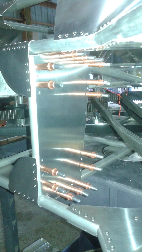
 Not shown are the flexible mounts scavenged from the original frame.
 A rubber liner was added to the bottom of the tray.
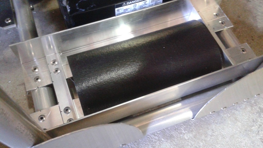
 Now all that remains to complete the Mk. II vehicle is to add to the electronics and the fuel tank. With some luck, the vehicle could be complete and running by Labor Day.
 More details can be found at:
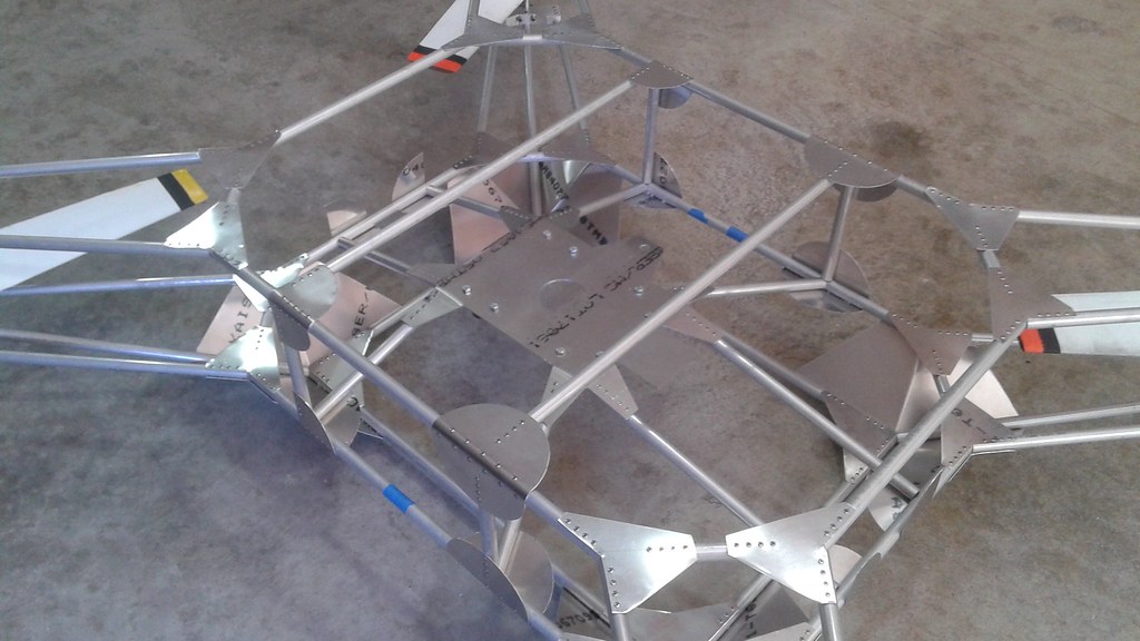 After attaching the engine mounting plate to the frame, the next step was assembling the lower frame. The lower frame is similar to the lower ring of the upper frame, so it was possible to reuse the jig for the upper frame with some minor modifications. This was simply making new wood rotor shaft mounts for the lower frame and swapping them out in place of the old ones. Then all of the lower frame elements were cut and placed in the jig.
 With all of the elements in place, the same process for riveting the gussets was followed.
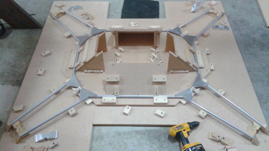
 Once the mounts were completed, the shaft mounts were attached with bolts to the lower frame in the same manner of the upper frame.
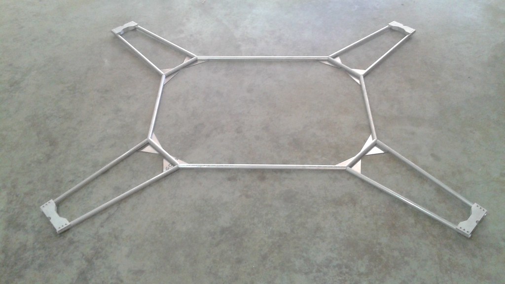 In the future the gussets would be attached to the top side of the lower frame. However, at this stage the method of attaching the idler pulleys and tensioners hadn't been finalized. Therefore the upper gussets were left off at this point.
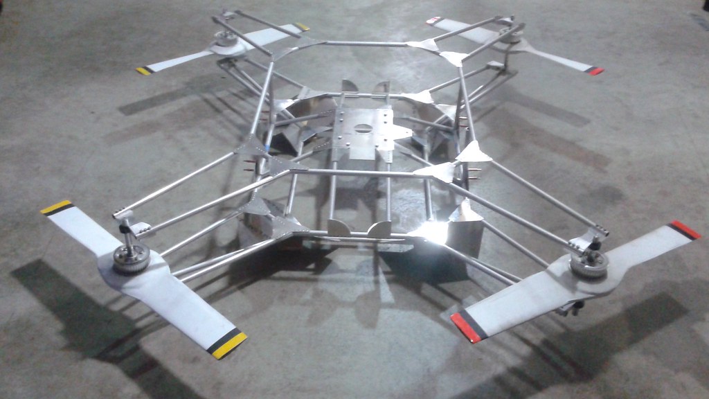 Four lengths of tubing were initially cut and attached on the sides of the frame along with the gussets for the lower frame. Clecos were used to hold the parts together prior to riveting.
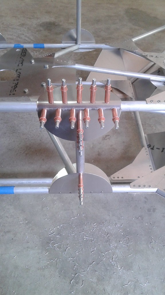
 With all of the new elements attached, it was time to riveting the parts and finalized the attachment between the frames. At that point the frame was flipped back over to see the progress.
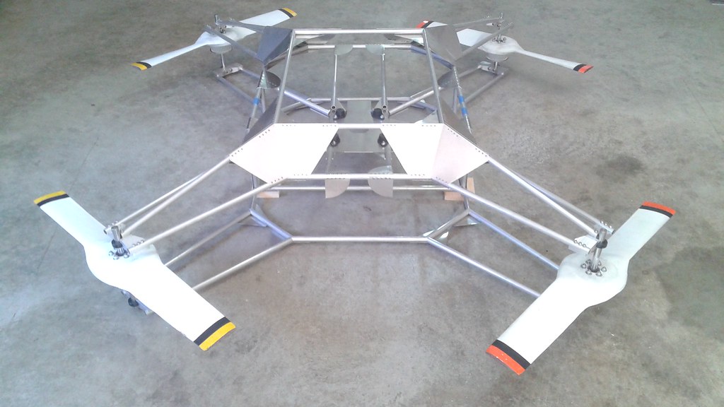 At this point about 80% of the frame is complete. the frame members at the front of back need to be added and some smaller cross members need to be added to stiffen the frame. However, before completing the frame elements, the attachment hardware needs to be completed to make sure there aren't any issues with the remaining structure. Once the attachment hardware has been finalized, then the frame can be finalized.
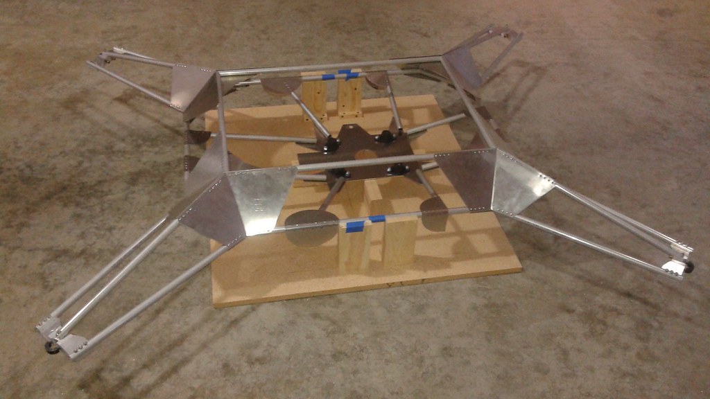 The first step was to start measuring and cutting the tubing that attach the engine mounting plate to the upper frame. This was starting by making a simple jig to hold the pieces at the right elevation to each other.
 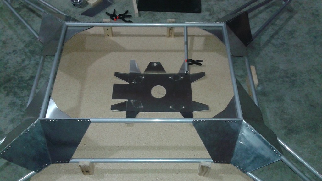 This worked for doing some preliminary alignment, but to make sure everything fit well, it was decided to redo the jig so that the engine could be placed on the vehicle while it was in the jig. This was done by further elevate all the pieces, with 2x4 blocks holding up the engine mounting plate.
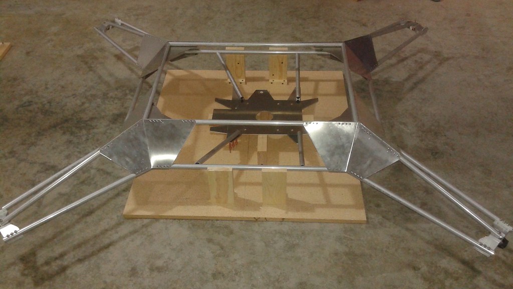 When all of the tubing was cut, the holes were drilled on the ends attached to the mounting plate and the parts were held together with Clecos.
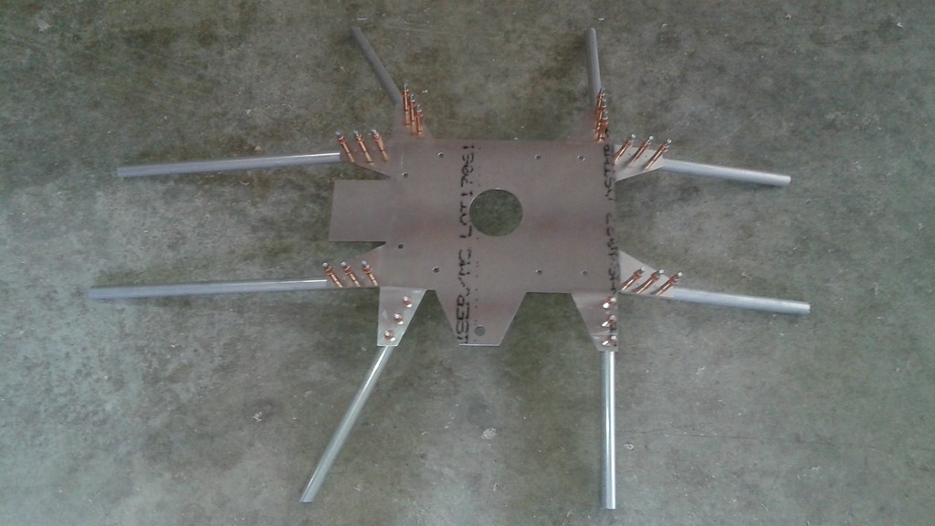 The plate with the tubes attached was put back in the jig and aligned with the upper frame. Then the gussets for the remaining joints were made and attached with more Clecos.
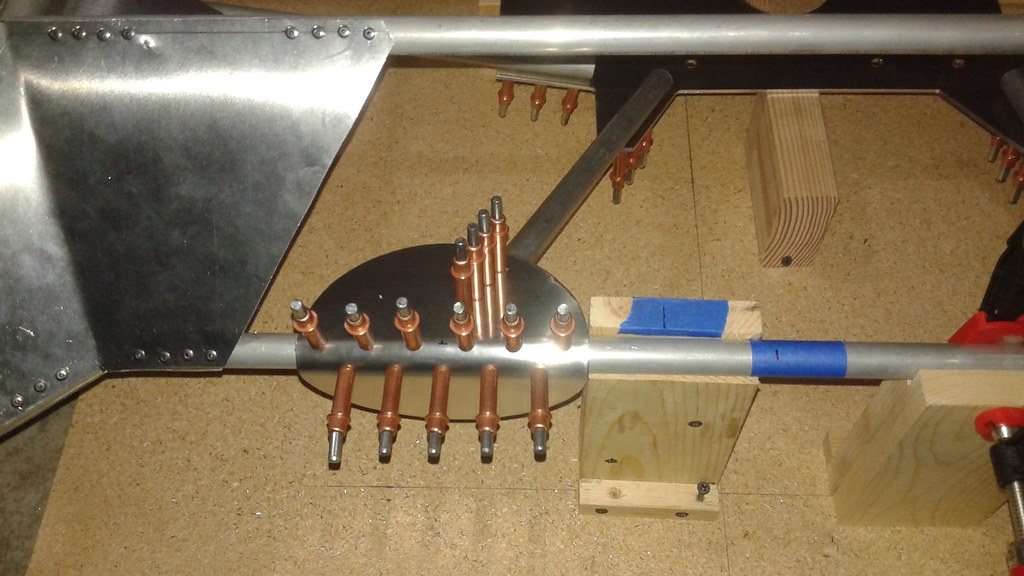 The gussets are wrapped around the tubing and will also serve as the attachment points between the upper and lower halves of the frame. This required bending the gussets with a larger 3/4" radius. To get a good radius bend, the press brake was used with a 3/4" diameter steel bar placed along side the sheet metal to provide the right shape for bending.
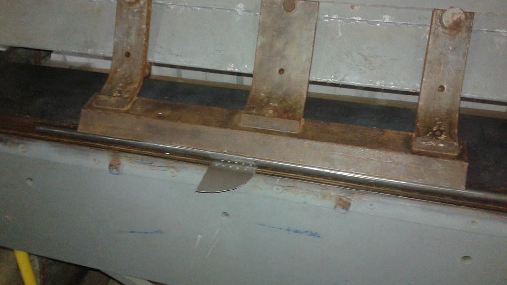 Once all the gussets were in place, the engine was mounted to double check that there was adequate clearance, before permanently attaching the plate to the frame.
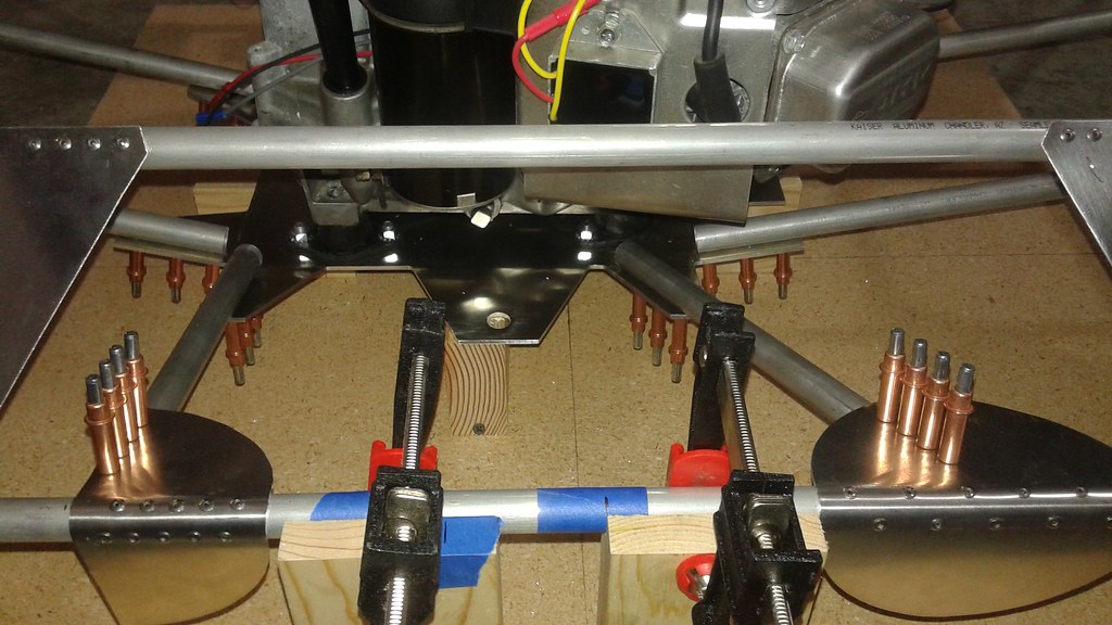 All of the clearances checked out and with no glaring design issues present, the rest of the rivets were pulled on the frame side of the tubes. Since there wasn't enough clearance to pull the rivets under the engine mounting plate, the frame was flipped over and the last of the rivets in the plate were installed.
 A quick note on the rivets for the engine plate. Rivets are designed to join a specific thickness of material. The 1/8" thick plate is thicker than the gussets, so slightly longer rivets had to be used. So care has to be taken to make sure the right rivets are used in the different locations.
 However, after holding the part inside the new frame a very big design flaw become apparent. The middle tabs were meant to be bent downwards, but that would place them in the way of the idler pulley, which will be placed below the engine plate. Second, I could go to both the lower and upper frame from the engine plate directly, otherwise the structure would have to pass through the belts. If that was done I'd have to assemble and re-assemble the frame every time the belts were added or removed.
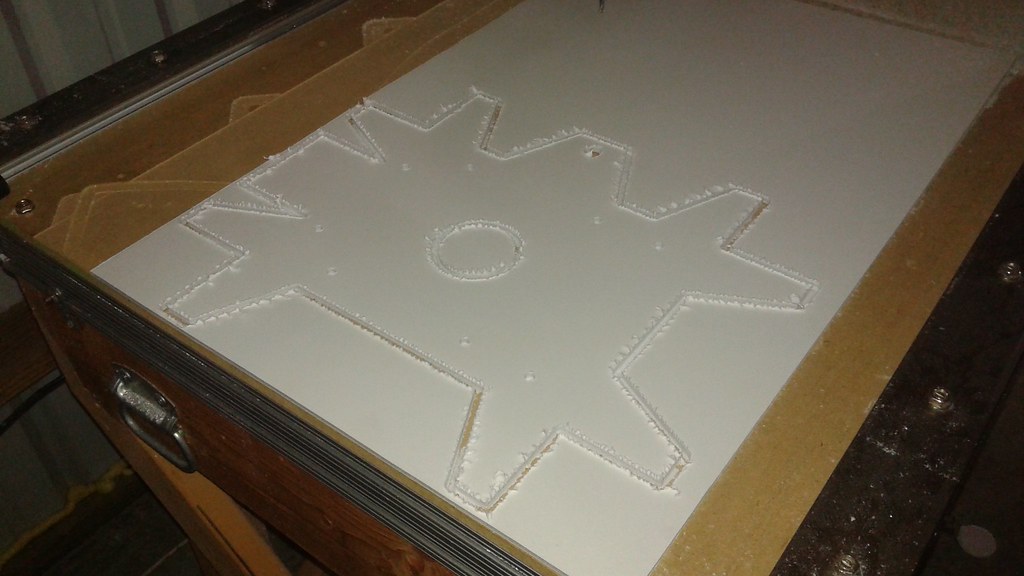 After a test fit, the design was complete and the part was ready to be machined using the aluminum plate. Since the CNC router needs to go slow to cut the aluminum plate, it took about an hour to cut the part. In the images, the edges of the plate look somewhat rough. This is actually the protective film that is on both sides of the plate. The actual edges come out very clean.
 After cutting, the tabs were bent to the correct angles using the press brake. The protective film has been left on to prevent marring the material.
 After getting all of the bends to the right angle, the mounts were placed on the plate and the engine was test fit to make sure all of the clearances looked good.
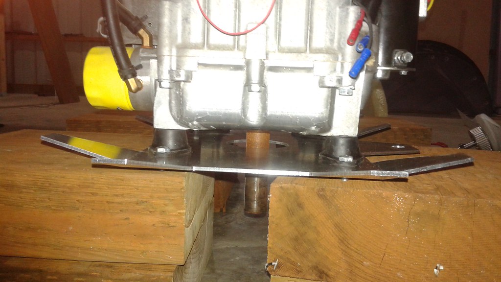
 The mounts for the Mk. II vehicle had to go from the shaft and mount to the three aluminum tubes that comprise the rotor arms. This required a custom part that could be bolted to the tubes and also act directly as the shaft mount, instead of using multiple shaft collars. The design process started by making a CAD object using Cubify Design.
 After that, the next step was making some prototypes out of wood on the CNC router.
 The fix was simply to slow down the feed rates and lower the spindle speed. After that the roughing passes came out a lot cleaner.
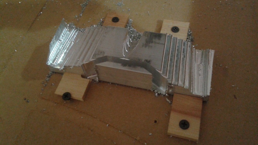 Once the roughing pass was done, a waterline pass was made.
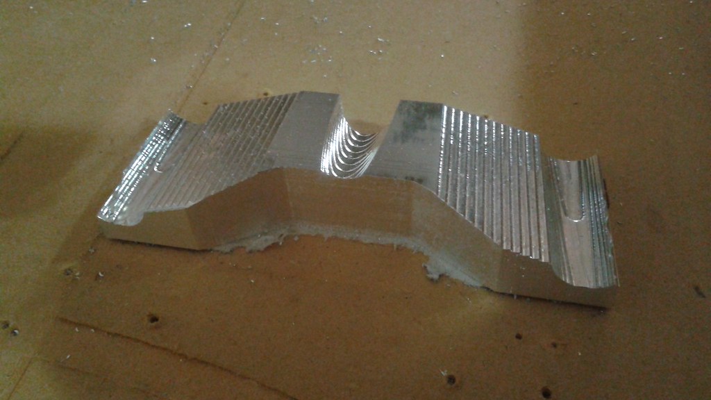 Next, a parallel pass was made in the Y-axis to clean up the upper surface.
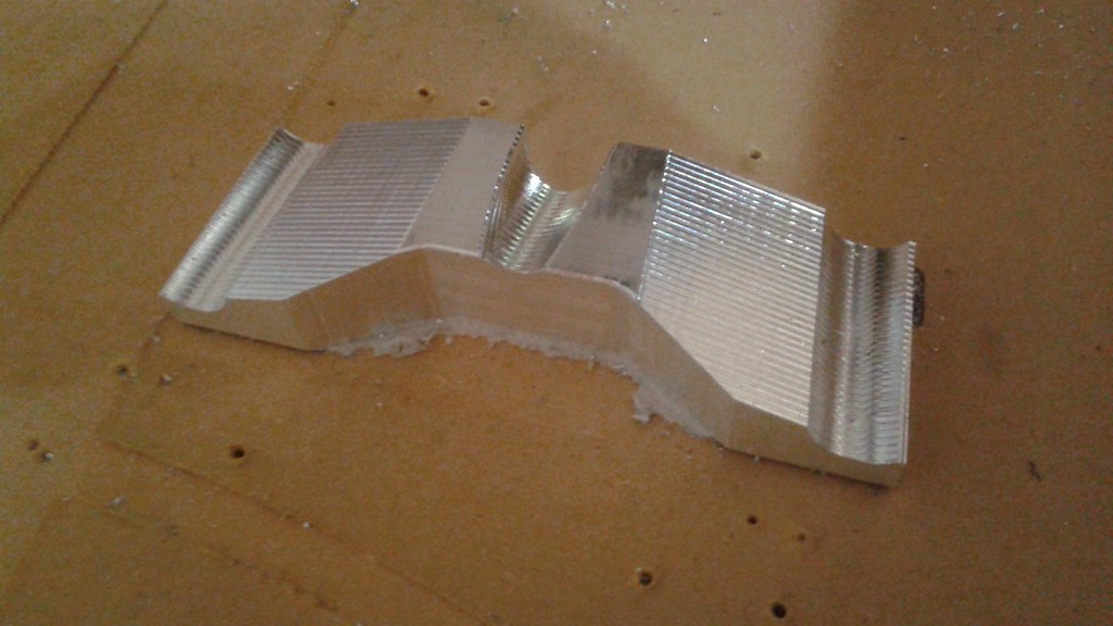 The last pass was with a 3/4" diameter ball end to clean up the grooves.
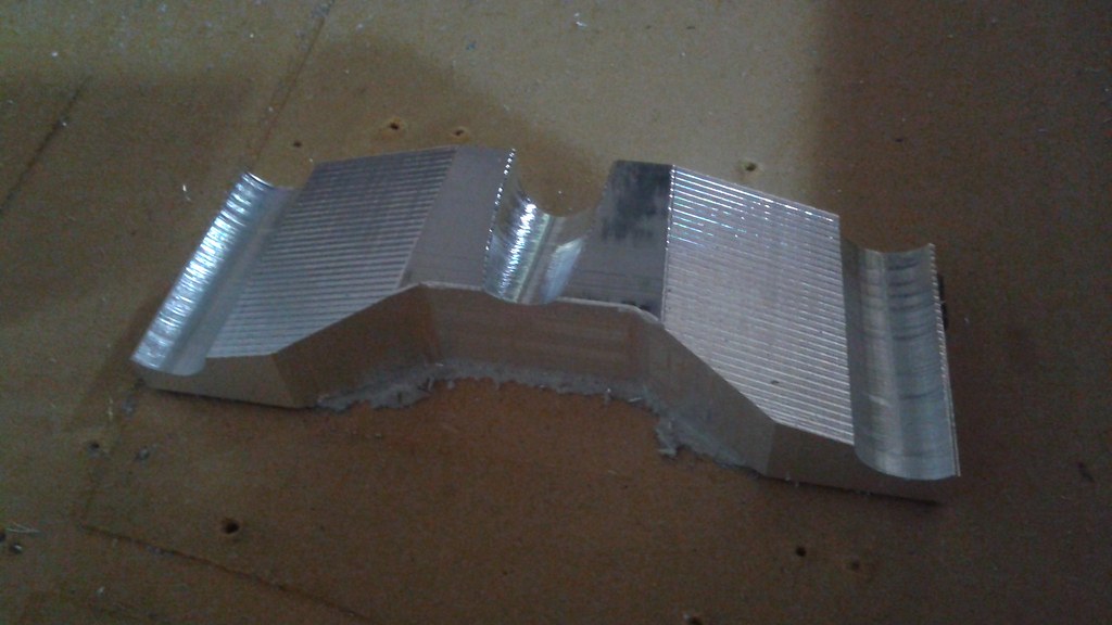 With the machining on the CNC Router done, the next step was to drill and countersink the holes for the bolts to mount to the frame.
 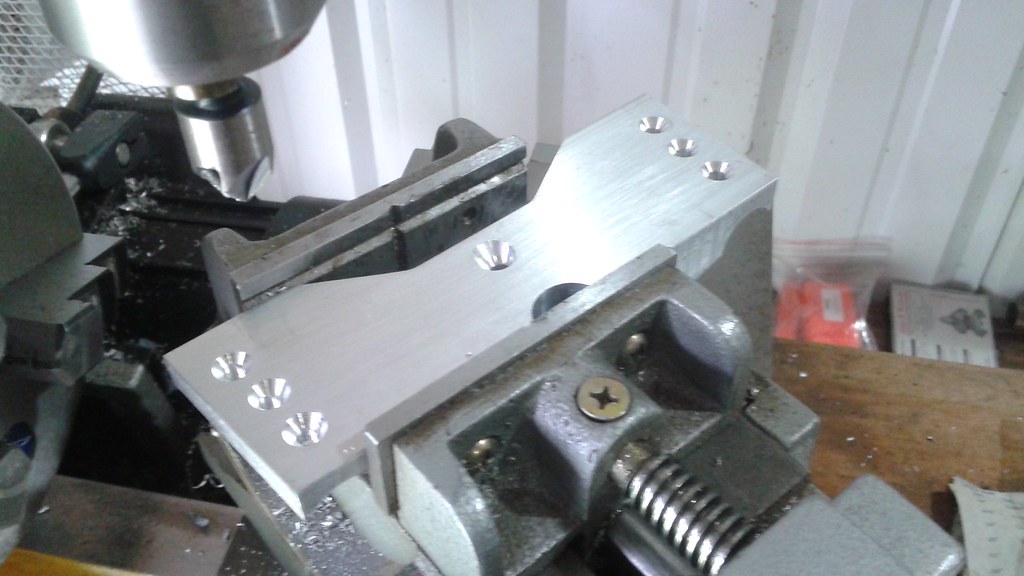 The last step was to drill the holes for the mounting.
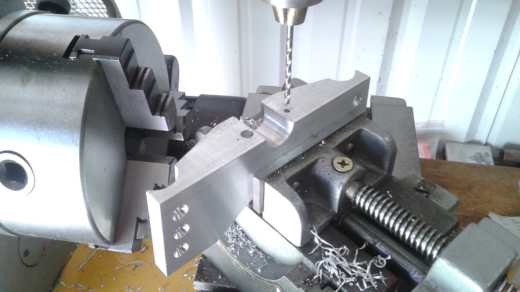
 The build process has been documented in
 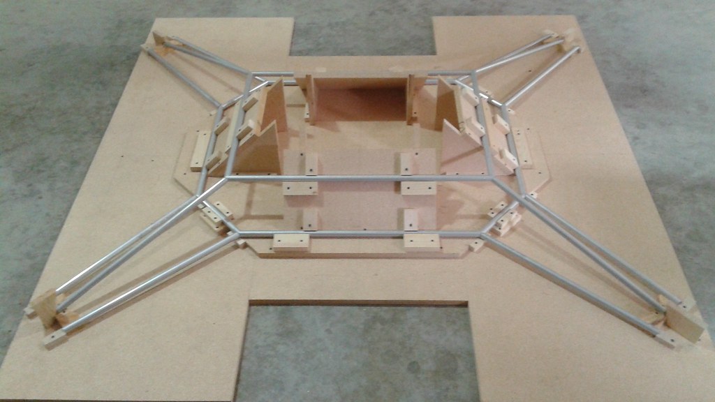 With the jig complete and the frame pieces cut, the next step was to start designing the gussets. Typically templates were cut out of card stock and refined until the shape was correct.
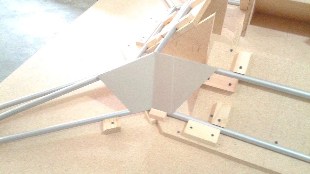 The templates were then used to trace out the shape on the 0.040" thick sheet metal and cut out with either tin snips or a jigsaw depending on the shape.
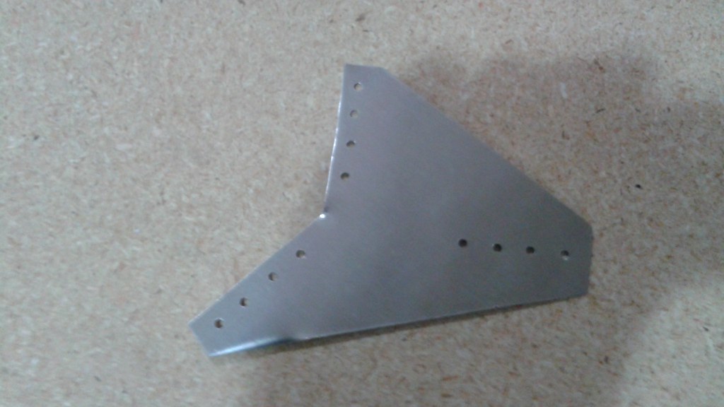 At this point there was a detour into another side project. The angle gussets needed to be bent using a press brake. Several years ago I obtained one cheap off of Craigslist and began to tear it down to clean it off since it had rust and lots of flaking paint. I got half way done cleaning it and then forgot about it. Then all the parts got packed up and moved across the country and the parts scattered about. So in order to use it, I first had to find all the parts and then remember how it went back together. Luckily after a bit of searching all of the parts were found
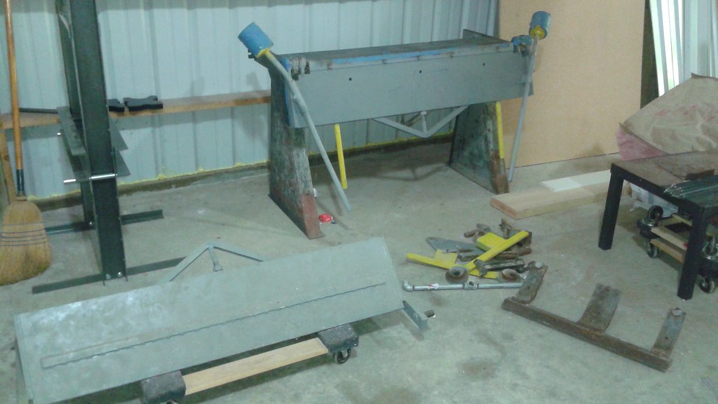 And even more fortunately, I remembered how it went back together after 4 years.
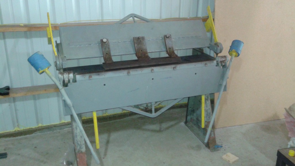 After completing the side project. The angle gussets were able to be completed.
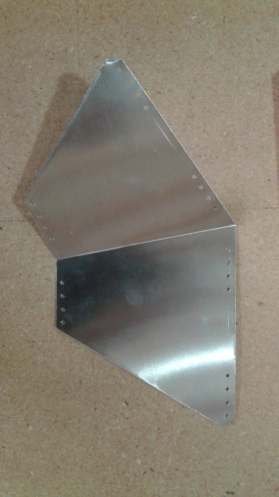 With the gussets completed, it was a matter of assembling all the parts. To get the best alignment, Clecos are used to hold the parts in place while other holes are drilled. Clecos are spring loaded and a special pair of pliers are used to insert them and remove them. Every other hole gets a Cleco and then the remaining holes get riveted together.
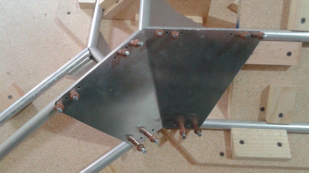
 Again, the step by step process is documented in the instructions. The next steps are to build the lower frame and to machine the rotor shaft mounts. More on the rotor shaft mounts next time.
 The light blue lines represent the truss with no loads. The blue lines represent the frame deflections under load with an exaggeration factor of 10x. Keep in mind that this is with no factor of safety, but the analysis suggests that the frame will see very small deflections. The primary reason is that that I chose the tubing size optimized on cost (just found the tubing with the lowest cost/foot ) and not by weight or stress.