 Peter McCloud
-
Goliath Mark II
05/26/2016 at 00:26 • 0 commentsWith the bugs worked out of the drive train and the belt and pulley configuration nailed down, it was time to take the project to the next phase. Work has already begun on a Mark II version of Goliath. The primary changes for the Mk II vehicle is a new lighter frame and ducts to enclose the rotors. Over the next couple weeks, there will be more project logs to document the new vehicle in more detail, but for now here's some of the progress that's been made.
Structure
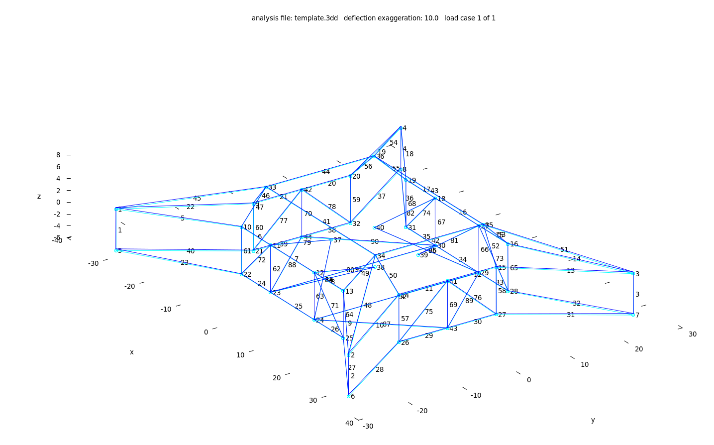
After considering several options, it was decided to go forward with an aluminum truss frame. The primary reason was cost and ease of manufacture. A composite structure would be lighter, but the cost would be significantly higher. A preliminary design has been completed and the structural analysis has been completed. Below is an image of the structure layout and the predicted deflections under load. More details will be provided in a later project log.
![]() The materials have been ordered and arrived this last week. Below is some of the tubing (3/4" and 1/2" diameter).
The materials have been ordered and arrived this last week. Below is some of the tubing (3/4" and 1/2" diameter).![]() However before the structure can be built, a jig is needed to assemble the parts. Work has begun on the jig for the upper portion of the vehicle.
However before the structure can be built, a jig is needed to assemble the parts. Work has begun on the jig for the upper portion of the vehicle.![]() Ducts
DuctsThe other big change for the Mk II vehicle is the addition of ducts. The duct serves a couple of purposes, the foremost of which is safety. The duct will prevent the rotors from hitting people or objects and to potentially contain debris if the rotor itself fails. Secondly, the duct will improve the total thrust of the vehicle, if designed correctly.
Each duct will be built in two halves to make building and assembling the ducts easier. A prototype duct piece has already been built to test out the manufacturing process. Eventually this duct will be tested on the new vehicle.
![]() The black material is the surface of the mold that stuck the duct because the directions for the mold release were misread.
The black material is the surface of the mold that stuck the duct because the directions for the mold release were misread.Stay tuned for more updates in the near future.
-
Vehicle back together and running smoothly
04/04/2016 at 22:11 • 1 commentA few tests back (Test 41), one of the rotor axles snapped, resulting in one of the rotors being damaged. The fix to this issue was to increase the shaft diameter to 3/4" from 5/8" and switch from using E-clips to retaining rings (project log with more details). Below is the new shaft with retaining rings holding the pulley in place.
![]()
A new rotor was built to replace the one that was damaged when the axle snapped. Both counter-clockwise propellers got a new paint job to make the tips more visible. Eventually the other set of propellers will get the same set of markings.![]() With all of the hardware fixed, it was time to test Goliath again. After a couple tests to make sure all of the hardware was secure and working properly, Goliath was run up to full throttle again.
With all of the hardware fixed, it was time to test Goliath again. After a couple tests to make sure all of the hardware was secure and working properly, Goliath was run up to full throttle again.The bad news is that Goliath still isn't flying. The good news is that it's REALLY close. The vehicle is bouncing around on the tethers indicating that the lift is nearly equal to the weight. The other good news is that the vehicle is running smoother than it ever has in the past. This is because the two cylinders are now firing correctly and improvements were made both to the pulley layout and to the tensioner.
Since Goliath wasn't flying, the next step was to figure out why. A friend let me borrow his optical tachometer. To avoid getting a signal from the overhead lights, the tachometer was mounted above one of the propellers and pointed downward.
![]() The vehicle was then run at different throttle settings and the RPM was recorded.
The vehicle was then run at different throttle settings and the RPM was recorded.Test 50 Throttle (%) RPM Starter 510 0 1740 25 2190 50 2850 75 3210 100 3240 It appears that above 75% throttle, there is very little increase in RPM. This is likely due to the rotors requiring too much torque to accelerate above 3200 RPM. Since the rotor pulley ratio is 1.1:1, this means the engine is running at 2945 RPM, short of the 3200 to 3400 RPM that had been targeted.
There are a couple of options available. One is to resize the pulleys closer to a 1:1 ratio. The pulleys were sized based on the power transfer capability. The main pulley is probably a little small since there still seems to be the occasional tooth skip at startup, so making it smaller to match the rotors isn't an option. All of the rotor pulleys would have to be bigger to make that work.
Another option is to make wider diameter rotors. The required power decreases as the rotor diameter is increased. The downside is that it will increase the vehicle footprint. It's already difficult to transport as it is, so it's more of a last resort option.
The option I'm currently leaning toward is to go ahead and build the ducts for the rotors. The ducts will decrease the power required by the props increasing the RPM speed. At the same time, if built correctly, the duct itself will act as a lifting surface. Literature suggests that the cumulative increase can be as much as 25%. That'd be about 55 lbs, based on the latest testing.
Pixhawk Logs
The last news of interest is that with the Pixhawk on-board, there is now quite a bit of data available. There is an interesting site for PX4 users where logs can be uploaded and the data is automatically plotted. The data for tests 48 and 49 are available at:
The bad news is that the accelerations are high (kind of expected that). Based on feedback (http://discuss.px4.io/t/using-a-px4-with-a-gas-engine/267) from the developers, the vibrations definitely need to be mitigated. This will have to be looked at in more detail down the road.
-
Pixhawk On-board
03/14/2016 at 05:11 • 0 commentsThe flight controller chosen for Goliath is the Pixhawk, running the PX4 flight stack. Up until now, integrating the flight controller hasn't been a priority. The design of the drive train is on-going, and there was the risk that the controller could be damaged or destroyed during testing.
With 40 tests now complete and the risk of losing the controller reduced, it was time to put the controller on-board Goliath for future testing. The controller won't actually be doing anything initially. The idea is to just make sure the controller can reliably operate while Goliath is running. Once it's proven it can operate, the next step will be to control the throttle and choke servos and eventually the ignition and starter relays.
The first step to get the Pixhawk on-board was to add the power module. On an electric quad copter, the power module goes in-between the battery and the ESC. The module is the primary source of power for the controller and also has a current sensing capability. Below is a picture of the power module from the Ardupilot documentation.
![]() On Goliath, the power module was placed between the alternator and the battery to measure the current being supplied by the alternator. The frame on Goliath acts as the ground path, so the XT60 connectors were cut off and the module was connected using the existing bullet connectors. Here's a photo of the power module mounted on Goliath (not yet grounded).
On Goliath, the power module was placed between the alternator and the battery to measure the current being supplied by the alternator. The frame on Goliath acts as the ground path, so the XT60 connectors were cut off and the module was connected using the existing bullet connectors. Here's a photo of the power module mounted on Goliath (not yet grounded).![]() The next step was placing the Pixhawk with the Delta 8 receiver and the safety switch on to the vehicle. The Pixhawk powers up when the master switch is turned on. The safety switch then has to be be triggered before the Pixhawk can be armed. Below is all of the hardware in place, but unsecured.
The next step was placing the Pixhawk with the Delta 8 receiver and the safety switch on to the vehicle. The Pixhawk powers up when the master switch is turned on. The safety switch then has to be be triggered before the Pixhawk can be armed. Below is all of the hardware in place, but unsecured.![]() The Pixhawk was successfully armed today and is properly logging the data and providing pre and post-flight summaries. The next step for the controller is to secure the hardware to get it ready for the next test.
The Pixhawk was successfully armed today and is properly logging the data and providing pre and post-flight summaries. The next step for the controller is to secure the hardware to get it ready for the next test.Additionally, work on the custom mixers and config file for Goliath has been started. The files can be found in the github repository at:
https://github.com/mccloudaero/goliath-quadcopter/tree/master/avionics
As for the next test, it shouldn't be too far off. All of the new axles and pulleys are complete and are just waiting on the new mounts to be finished before they can be placed on the vehicle. The new rotor has been epoxied and came out the vacuum bag in good shape. It'll be ready after a few rounds of sanding and primer.
-
Engine Issues Resolved
03/05/2016 at 05:02 • 3 commentsDuring the most recent tests, Goliath exhibited more vibration than was seen in earlier tests. After closer examination, it became apparent that the starboard cylinder was not firing. Test 41, when the axle broke, was an attempt to see if the engine had been fixed. Due to the vibration present during Test 41, the starboard cylinder was still not firing.
The usual suspects to check for with a small engine is compression (air), fuel, and spark. There was obviously fuel getting to the cylinder since it's coming out the exhaust pipe. Spark was testing by removing the plugs, resting the ground side against the engine and running the starter. Both cylinders showed good spark. The last test was a compression test. Briggs and Stratton doesn't state minimum compression values, just that both cylinders should be tested and that they should come out the same.
So with all those items checked out, it was quite puzzling as to what the real issue was. I took a trip to a local small engine shop to get some help. It was the right place to go because the guy there gave me great help. He suggested two possibilities. The first was to check the value clearances, that perhaps the hardware holding the values in place had come loose. The second possibility was that there was a bad diode connected to one of the ignition coil.
The valves checked out ok, so the diode was the next thing to check out. What's makes this particularly difficult, is that there is no documentation provided by Briggs and Stratton on these diodes expect for the repair manuals, which are difficult to come by. After removing the wire harness it was very obvious that the starboard diode was failed.
![]() The failure modes are pretty interesting. The ignition switch works by grounding the ignition coils. The diodes act as a bridge to isolate the two coils from each other. When one of the diodes fail closed, the coil it's connected is no longer isolated from the other coil. When the other coil fires, it grounds the coil connected to the failed diode, preventing it from firing. This was precisely what happened on Goliath.
The failure modes are pretty interesting. The ignition switch works by grounding the ignition coils. The diodes act as a bridge to isolate the two coils from each other. When one of the diodes fail closed, the coil it's connected is no longer isolated from the other coil. When the other coil fires, it grounds the coil connected to the failed diode, preventing it from firing. This was precisely what happened on Goliath.With the cause identified, the next step was to repair the wire harness with the diodes. The diodes are potted in a clear plastic, so the failed diode was visible through the coating. It was difficult to get a good shot up close to show the charring.
![]()
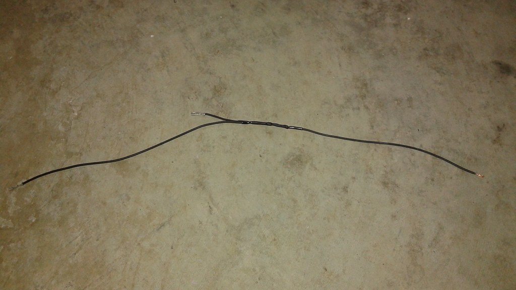
Typically the wire harness is replaced as a whole, is specific to the engine make and model and has to be special ordered. Instead the harness was torn down and the diodes part numbers were identified (IN4007). This is was simply a matter of getting the diodes from Radioshack and soldering the harness back together.
![]() The new hardware to repair Goliath with is in the process of being built, so the engine was tested with just a single belt and one pair of rotors to ensure that the engine was indeed fixed.
The new hardware to repair Goliath with is in the process of being built, so the engine was tested with just a single belt and one pair of rotors to ensure that the engine was indeed fixed.The test was a success. Both cylinders are firing and the engine now runs much smoother. The increase in power is also clearly visible, with Goliath lifting up the one side with the two rotors. Looking at the video in slow motion, it's clear that one of the tethers reached it's full extension.
After the new hardware is complete, Goliath can be fully reassembled and further testing can be conducted.
-
Broken Rotor Axle
02/17/2016 at 16:28 • 0 commentsTest 41 was to determine if the starboard engine was working correctly again. After idling the engine for a while, the rear starboard rotor axle broke.
Looking at the slow motion video, it's clear that the axle breaks, and then the belt tension pulls the pulley inwards. This caused the rotor to hit support arms and sheared off a piece of the rotor. The double sided belt then falls off all the pulleys since the tension has been lost. Here are some pictures of the damage.
![]()
![]() The rotor is the biggest issue, since a new one will have to be manufactured. The rotor pulley flange was dislocated as the belt came off, but it should be a simple fix to press it back on.
The rotor is the biggest issue, since a new one will have to be manufactured. The rotor pulley flange was dislocated as the belt came off, but it should be a simple fix to press it back on. As hindsight is 20/20, it's fairly obvious that adding the grooves for the E-clips made it so the remaining material was insufficient to handle the loads. A 0.07" groove depth didn't seem like much, but the remaining material was only 0.485" in diameter, significantly less than the 0.625" shaft diameter.
The plan is to switch to 0.75" axles and bearings for the rotors. The new bearings are the same external size, so the pulleys won't have to be modified. The E-Clips will also be replaced with retaining rings. The rings won't be as easy to install or remove, but they only require a groove depth of 0.023", leaving 0.704" of material.
The new hardware has been ordered and the process of building the new rotor has been started. Meanwhile, the engine still appears to be running rough, so that will hopefully be addressed by the time all of the new hardware is ready in a couple of weeks.
-
New Rotor Pulleys Working, New Engine Issues
02/15/2016 at 06:17 • 0 commentsProgress
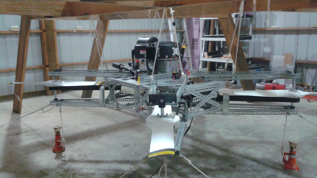
All of the new rotor pulleys have been installed and have been tested for a cumulative run time of 20 mins. (The video has yet to be edited together).) The great news is that there have been no occurrences of rotor bolts breaking and the new hardware is significantly lighter. For the last full power test (#21) the vehicle weighed 238 lbs. For the latest tests, the vehicle is now down to 213.8 lbs.
![]()
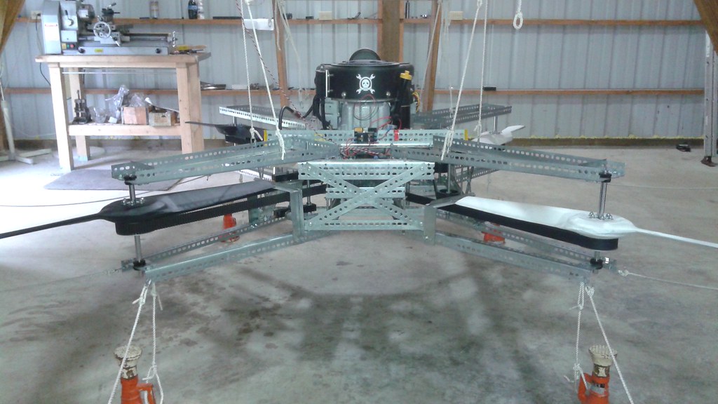
This was mostly due to switching to the aluminum rotor pulleys, but some additional weight reduction came from trimming off the excess material for the arms supporting the rotors. Here's a shot of the vehicle in its current configuration.
![]()
The excess length had been left on in case the rotor pulleys needed to be shifted outboard. Now that the design has had time to mature, the likelihood of moving the arms outboard seems low. There is still sufficient clearance to increase the prop diameter easily up to 40 inches if needed.
Tension Issues
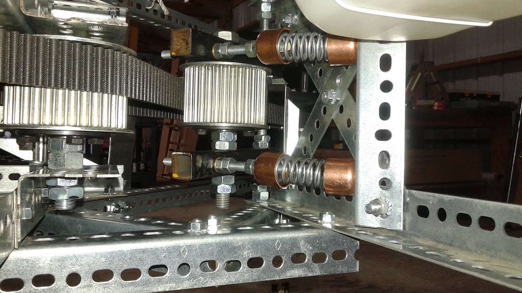
The tension on the single sided belt is just right. The teeth haven't skipped and the tensioner hasn't had to be readjusted for the last 10 minutes of testing. This is due to improvements made to the tensioners. Prior to the changes, the all thread that holds the springs in place would sometimes bind up where it passes through the structure supporting it. The fix was to hold the spring captive with end caps fashioned from copper pipe caps. Below is the latest iteration of the double sided belt tensioner. This design also helps by allowing for a small degree of misalignment, allowing the tensioner assembly to rotate freely.
![]() Getting the tension correct on the double sided belt has been more problematic. The teeth occasionally skip on the double sided belt, particularly when the engine decelerates and more slack builds up. Several different tensioner configurations have been tried and none of them have completely solved the problem yet. The latest configuration appears to be promising, but fixing the tensioner has been put on hold since some engine issues have developed.
Getting the tension correct on the double sided belt has been more problematic. The teeth occasionally skip on the double sided belt, particularly when the engine decelerates and more slack builds up. Several different tensioner configurations have been tried and none of them have completely solved the problem yet. The latest configuration appears to be promising, but fixing the tensioner has been put on hold since some engine issues have developed.Engine Issues
In the twenty minutes of testing after all of the the new rotor pulleys were installed, the engine runs reasonably at idle. However, when the throttle is increased, the engine appears to bog down and the RPM does not increase. Part of the problem could be the tension issues with the double sided belt. However, the tensioners haven't been completely right in the past and the vehicle was able to get up to higher RPMs. The first sign that something else was wrong showed on the exhaust pipes. In the picture below there is a visible difference between the two exhaust pipes, with liquid present on the starboard exhaust pipe.
![]() At first glance it looked like oil, but upon closer inspection it appears to be mostly gas and soot. The spark plug on the starboard side was examined and it, too, was covered in a gas/soot mixture, which likely means the cylinder isn't firing. Below is a picture of the spark plug from the suspect cylinder.
At first glance it looked like oil, but upon closer inspection it appears to be mostly gas and soot. The spark plug on the starboard side was examined and it, too, was covered in a gas/soot mixture, which likely means the cylinder isn't firing. Below is a picture of the spark plug from the suspect cylinder.![]() For comparison, here's a picture of the spark plug from the port cylinder that appears to be running fine
For comparison, here's a picture of the spark plug from the port cylinder that appears to be running fine![]()
It's not clear yet why the cylinder isn't firing. The next step is to do some additional troubleshooting. Once the cylinder is firing again, the tensioner issue can be addressed. It could be that the engine running rough on one cylinder could be the cause for the double sided belt skipping teeth. Either way, once both of those issues are resolved, then the next full throttle test can be performed.
-
Bearings and Axles
01/29/2016 at 00:20 • 0 commentsIn the previous project log, the first of the new rotor pulleys with the new axles had been tested. The new hardware was considered to be good because nothing broke (yes, not breaking is a low bar to set). The next step was supposed to be assembling the rest of the rotor pulleys and axles and doing a more complete test.
Two things happened after that. The first as that there was a question regarding the fit of the axles. It wasn't required to press fit the axles into the rotor pulleys, which shouldn't have been the case. The second was an unidentified noise during the testing. The first hint of an answer to the second question came to me from YouTube user +visnevskiscom, who commented that during the latest video at 2:30 there was a vertical oscillation that appeared to correspond to the noise. After investigating this further, the source of the noise was found to be the rotor hitting the belt occasionally. It turns out that there was slight amount of play between the axle and the bearing to allow the rotor to wobble just slightly and just clip the belt.
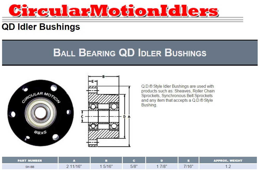
This led back to the suspicion that something wasn't right about the interference fit. The axles had just been ordered from McMaster Carr and the drawing states that the axle was 0.625" +0.000/-0.001". The bearings were pulled out of a set of idlers almost two years ago, and I knew less about. Below is the product page that hasn't changed from when the bearings were ordered. (link to site)
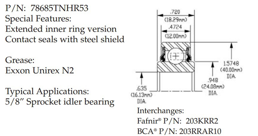
So the inside diameter is stated to be 5/8" (0.625"). There is no tolerance set, so in theory the ID could be just slightly greater than 0.625" and the shaft could be a thousandth less and it wouldn't need an interference fit. Since there wasn't any more information from Circular Motion, I looked up the bearing part numbers and did some internet searching. It appears that the bearing is a specialty bearing and was hard to get the specs for, but after a while I did find a drawing. (link to site)![]()
The typical applications is stated to be a 5/8" sprocket idler bearing. However the drawing states that the ID is 0.635" , 0.01" larger than what Circular Motion states the ID to be. I don't know enough about sprocket idler design to know why the bearing is 0.01" larger that the nominal ID or if doing so is a standard practice. What is clear is that the current bearings wouldn't work with standard axle shafts (and that I'll never order another bearing without seeing a drawing sheet)![]()
After a short period of despair, thinking about the amount of time and money that went into a set of rotor pulleys that had useless bearings, a reasonable solution was found to the problem. It turns out that a bearing was available from McMaster-Carr that not only would fit the shafts correctly (0.625 +0.0000/-0.0005), the rotor pulleys just needed to be bored out just slightly larger to accommodate the new bearings AND they're cheaper.
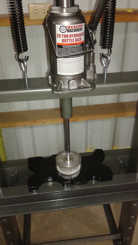
So after ordering a new set of bearings, boring the bearing pockets to be larger, and installing the new bearings, the hardware was reassembled. This time the bearings and the axles required a press to fit them together:
![]() Test 29 was mostly a repeat of Test 28. This time around, two of the new rotor pulleys were tested, both mated to the new axles. The latest revision of the flight rotors were also used.The test went well and there were no unidentified noises. The rotor bolts continue to hold up. The next step is now to complete the other rotor assemblies.
Test 29 was mostly a repeat of Test 28. This time around, two of the new rotor pulleys were tested, both mated to the new axles. The latest revision of the flight rotors were also used.The test went well and there were no unidentified noises. The rotor bolts continue to hold up. The next step is now to complete the other rotor assemblies. -
Testing New Rotor Pulleys and Axles
01/02/2016 at 17:51 • 0 commentsThe new rotor pulleys and axles are starting to be tested. At the end of November, the first rotor pulley as completed and before moving on to the other 3 pulleys, the first pulley was tested to ensure that the design was acceptable. To do this, Goliath was set up with just the single sided belt, with the new pulley with the original flight rotors and one old pulley with a dummy rotor. The original flight rotors were used so that if something breaks, I won't run the risk of having to make more update rotors. This test was number 27. The video for tests 27 and 28 is below:
The first test went well. The rotor was run at idle for a while and the new pulley showed no issues and all of the bolts held. The one thing that is obvious in the video is that the nut underneath the pulley comes loose. The nuts above and below the pulley are held in place with external toothed lock washers. The don't always hold though, probably because it's difficult to tighten the nuts correctly when the rotor is attached to the pulley. After gaining some experience with machining the rotor pulleys, it was time to start making custom axles.
The axles are just 5/8" drive shafts, 12" long (5947K14 from McMaster-Carr). The drive shaft and rotor are held in place using bowed E-clips (98398A140 from McMaster-Carr). I was a little hesitant to use E-clips to hold the thrust from the rotors considering they are only grabbing onto a small groove in the shaft. A look a the specs though show that the E-Clip is rated to about a 1000 lbs. The rotors will be putting out 70 lbs at max thrust, so there's a Factor of Safety of about 14.
The machining went ok. I don't have the right grooving tools for this, but those are more expensive. If I end up doing this more, I'd get more appropriate tooling. Here's a shot of one of the grooves.
![]() Below is the E-clip compared to the bearings that are used. (Note this was just a test fit with the bearings in the old bushings)
Below is the E-clip compared to the bearings that are used. (Note this was just a test fit with the bearings in the old bushings)![]()
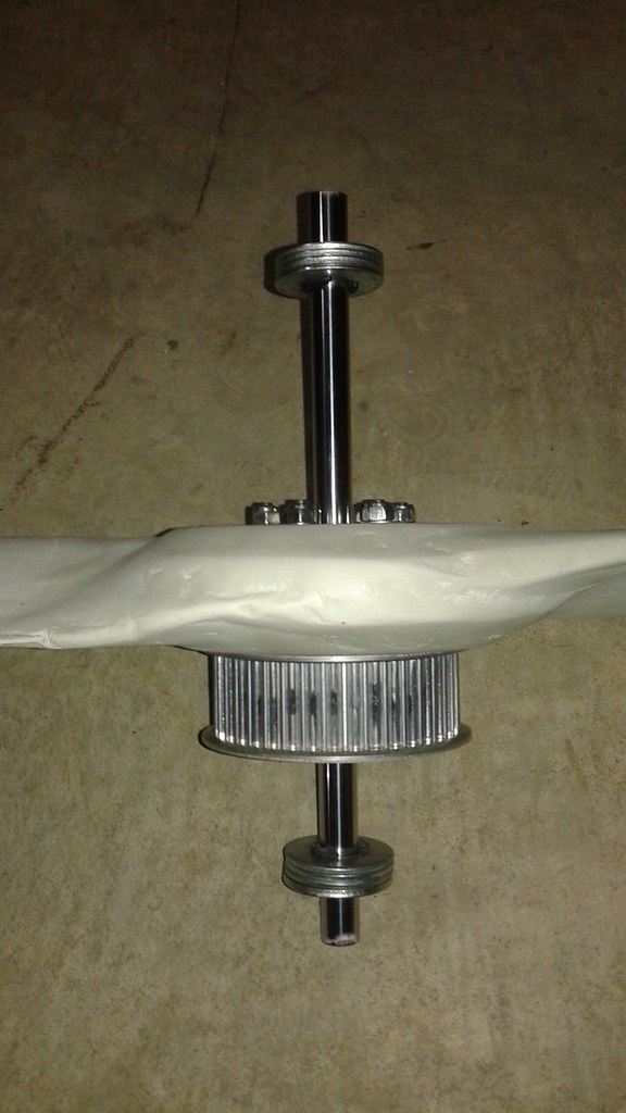
The overall axle has six grooves. Where the axles attach to the frame, I've left room for large washers to act as shims. This way I can adjust the height +/- the width of one of the washers. Once assembled the axles simply slides onto the frame with the frame between two of the washers.
![]()
The entire assembly with the axle, E-clips, shims, rotor, rotor pulley and rotor bolts weighs 4.9 lbs.For test 28, Goliath was configured again with just the single sided belt. One of the rotors has the new pulley and the new axle. The other rotor has a new pulley, but with the old axle setup. Both rotors have the original flight rotors.
The pulleys are still holding up and the axle also didn't have any issues. There is some unidentified nose in the test, that needs to be figured out. Either the belts are getting clipped by the rotors or the tensioner isn't configured correctly. That issue needs to be figured out and then additional testing can be done with more hardware.
-
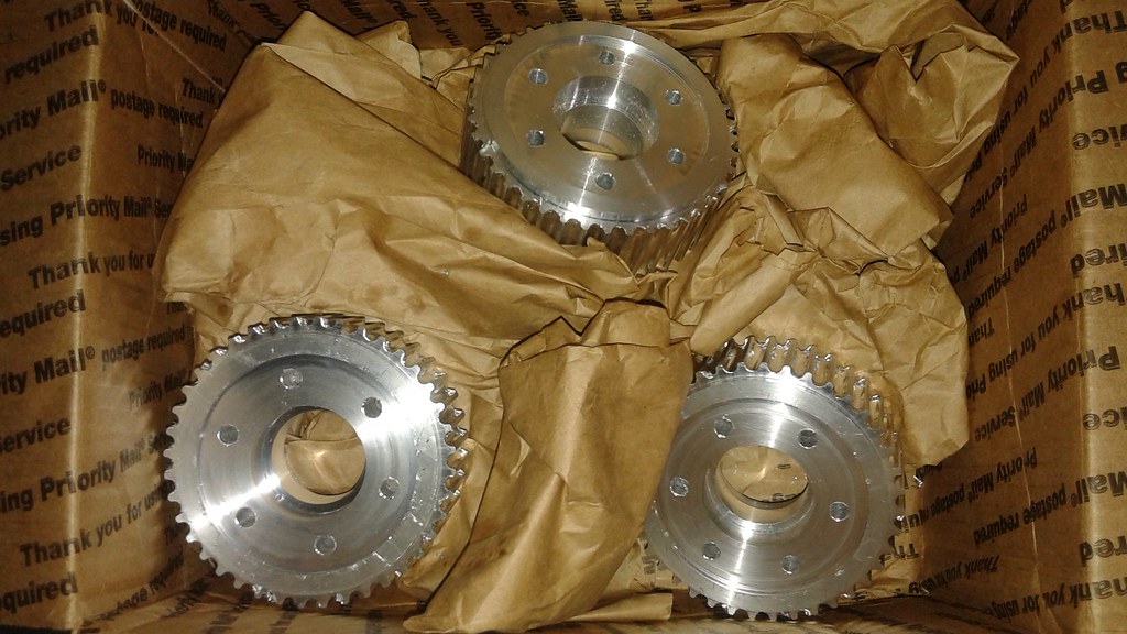
Rotor Pulley Machining Complete
12/25/2015 at 19:41 • 0 commentsThe remaining three rotor pulleys are nearly complete. The most time consuming part, the machining, is now complete. Everything went smoothly making the parts, which I was not expecting since this is my first time making these types of parts. Here is a shot of the pulleys together:
![]() After adding the bearings and the flanges to the pulleys, it'll be time again to start re-assembling the vehicle and begin testing again, hopefully before the new year. For the next round of testing, the original set of rotors will be used initially in case something doesn't go right. Once the new pulleys have been tested and shown to work, then the latest rotors will be put on the vehicle.
After adding the bearings and the flanges to the pulleys, it'll be time again to start re-assembling the vehicle and begin testing again, hopefully before the new year. For the next round of testing, the original set of rotors will be used initially in case something doesn't go right. Once the new pulleys have been tested and shown to work, then the latest rotors will be put on the vehicle.One other upgrade which may also be done by the next test is adding solid axles with bowed E-clips to hold the rotors in place. The current all-thread axles aren't well suited to their task and the nuts holding the rotors in place continue to come loose in spite of using the star type lock washers. I'm confident the rotors won't need to be adjusted height wise anymore, so it seems to be time to make the upgrade.
-
First Custom Pulley Finished
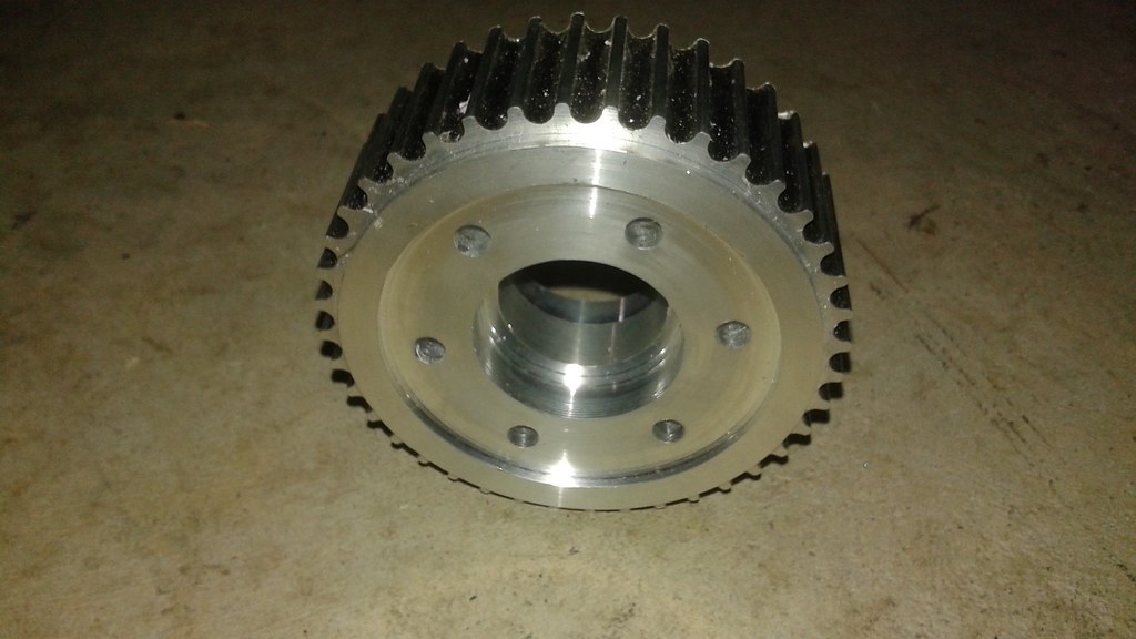
11/23/2015 at 05:25 • 1 commentThe first of the custom pulleys was completed today. The custom pulleys are aluminum instead of steel and allow for six fitted mounting bolts instead of three fully threaded bolts. Here's an image of the new custom pulley connected to one of the previously used rotors.
![]()
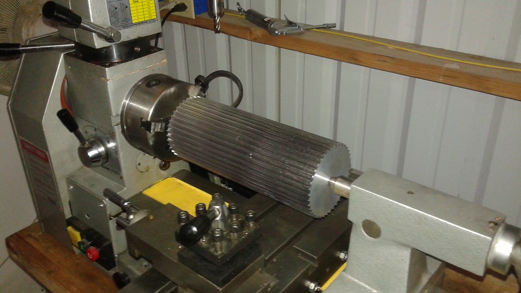
The custom pulleys are started from a 10" length of pulley stoc. Below is the stock mounted in the lathe.
![]()
I won't go through all of the steps here. The manufacturing steps were outlined in the previous log and updated to reflect the as-built process. All of the photos showing each of the steps are in a Flickr album. Here's a shot showing the part after the machining was complete:
![]() Next, the flanges were put in place and a punch was used to roll over the edge in six spots to hold the flange in place. The bearings were press fit in place.
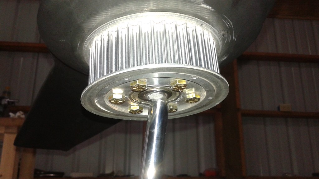
Next, the flanges were put in place and a punch was used to roll over the edge in six spots to hold the flange in place. The bearings were press fit in place.![]() Here's a shot with the six bolts holding the rotor in place. I'm confident this will solve the issue with the bolts breaking.
Here's a shot with the six bolts holding the rotor in place. I'm confident this will solve the issue with the bolts breaking.![]()
The next step is to mount the new pulley onto Goliath and run a test to ensure that it doesn't have any issues. If that test is successful, then the other rotor pulleys can be manufactured.
 The materials have been ordered and arrived this last week. Below is some of the tubing (3/4" and 1/2" diameter).
 However before the structure can be built, a jig is needed to assemble the parts. Work has begun on the jig for the upper portion of the vehicle.
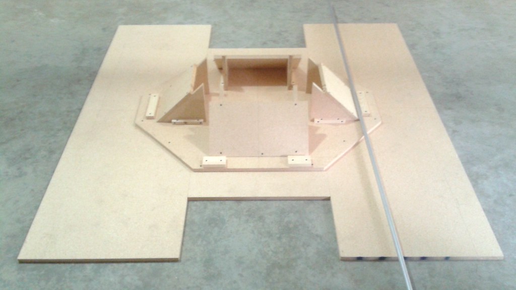 Ducts
Ducts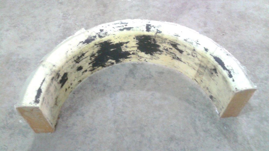 The black material is the surface of the mold that stuck the duct because the directions for the mold release were misread.
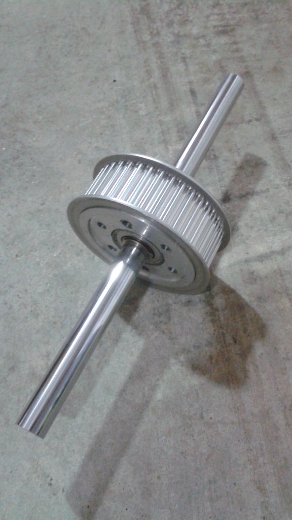
 The vehicle was then run at different throttle settings and the RPM was recorded.
 On Goliath, the power module was placed between the alternator and the battery to measure the current being supplied by the alternator. The frame on Goliath acts as the ground path, so the XT60 connectors were cut off and the module was connected using the existing bullet connectors. Here's a photo of the power module mounted on Goliath (not yet grounded).
 The next step was placing the Pixhawk with the Delta 8 receiver and the safety switch on to the vehicle. The Pixhawk powers up when the master switch is turned on. The safety switch then has to be be triggered before the Pixhawk can be armed. Below is all of the hardware in place, but unsecured.
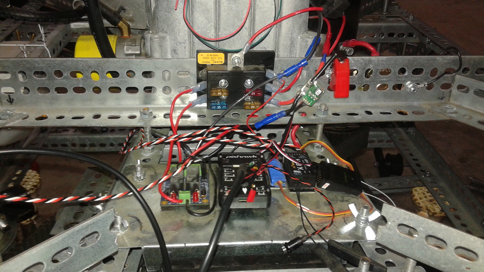 The Pixhawk was successfully armed today and is properly logging the data and providing pre and post-flight summaries. The next step for the controller is to secure the hardware to get it ready for the next test.
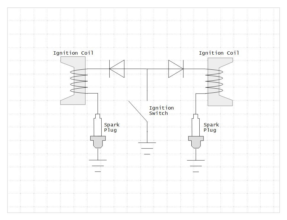 The failure modes are pretty interesting. The ignition switch works by grounding the ignition coils. The diodes act as a bridge to isolate the two coils from each other. When one of the diodes fail closed, the coil it's connected is no longer isolated from the other coil. When the other coil fires, it grounds the coil connected to the failed diode, preventing it from firing. This was precisely what happened on Goliath.
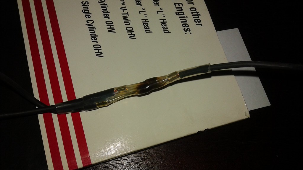
 The new hardware to repair Goliath with is in the process of being built, so the engine was tested with just a single belt and one pair of rotors to ensure that the engine was indeed fixed.
 The rotor is the biggest issue, since
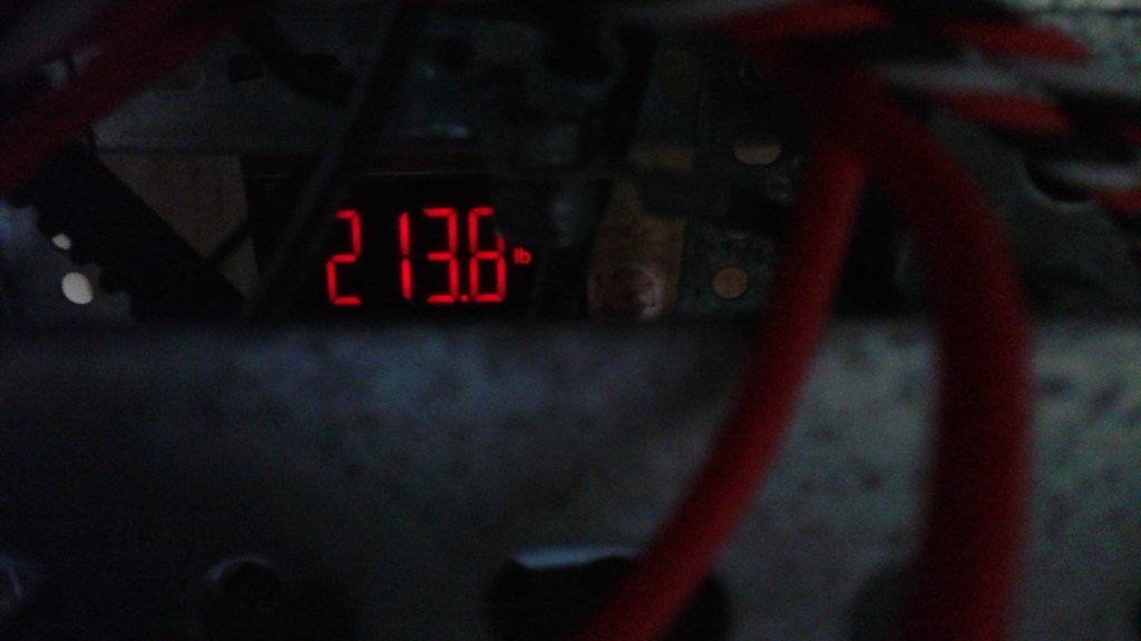
 Getting the tension correct on the double sided belt has been more problematic. The teeth occasionally skip on the double sided belt, particularly when the engine decelerates and more slack builds up. Several different tensioner configurations have been tried and none of them have completely solved the problem yet. The latest configuration appears to be promising, but fixing the tensioner has been put on hold since some engine issues have developed.
 At first glance it looked like oil, but upon closer inspection it appears to be mostly gas and soot. The spark plug on the starboard side was examined and it, too, was covered in a gas/soot mixture, which likely means the cylinder isn't firing. Below is a picture of the spark plug from the suspect cylinder.
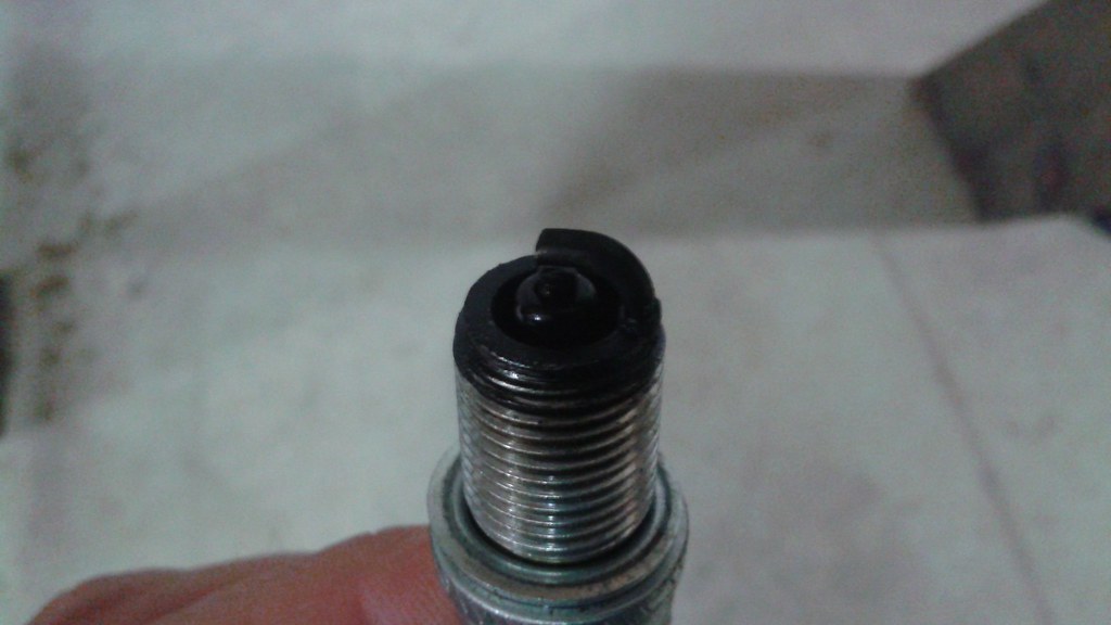 For comparison, here's a picture of the spark plug from the port cylinder that appears to be running fine
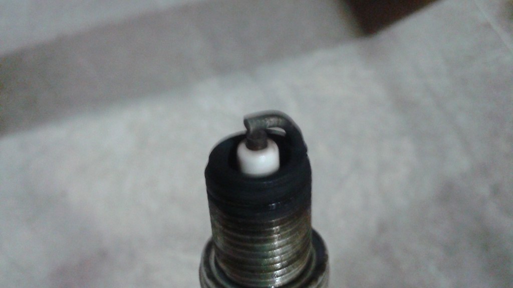
 Test 29 was mostly a repeat of Test 28. This time around, two of the new rotor pulleys were tested, both mated to the new axles. The latest revision of the flight rotors were also used.
 Below is the E-clip compared to the bearings that are used. (Note this was just a test fit with the bearings in the old bushings)
 After adding the bearings and the flanges to the pulleys, it'll be time again to start re-assembling the vehicle and begin testing again, hopefully before the new year. For the next round of testing, the original set of rotors will be used initially in case something doesn't go right. Once the new pulleys have been tested and shown to work, then the latest rotors will be put on the vehicle.
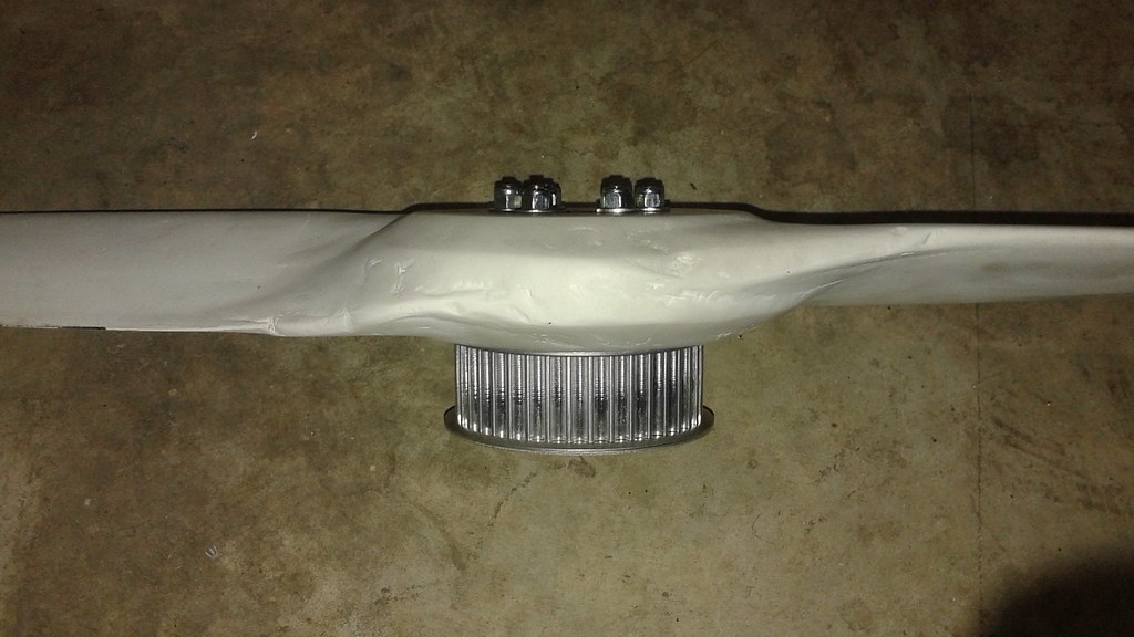
 Next, the flanges were put in place and a punch was used to roll over the edge in six spots to hold the flange in place. The bearings were press fit in place.
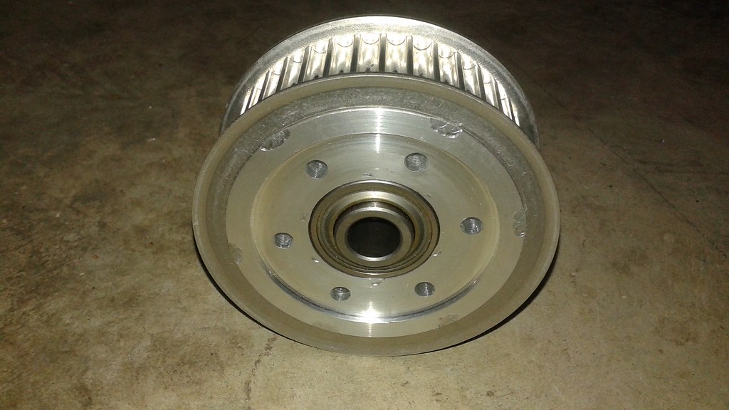 Here's a shot with the six bolts holding the rotor in place. I'm confident this will solve the issue with the bolts breaking.