 Peter McCloud
-
Checking the Numbers
03/07/2015 at 16:28 • 0 commentsDuring the last test, Goliath was run at full throttle and failed to hover. One thing I did find after going over the vehicle the next day was that the choke was set to 25%. This would prevent the engine from producing full power. I haven't had the opportunity to go back and retest yet. I'd also like to instrument the test stand to measure the thrust before doing any testing. Along those lines I've started a separate hackday project, Drone Test Stand to document those details, so if you're interested in that check it out!
However, before getting into modifying the test stand, the first thing I did was to go back and check the calculations to make sure the engine can produce enough lift. There's been a couple of comments around the interwebs stating that 30 Hp isn't enough to the lift Goliath. I've double checked the numbers before, so I guess it's triple-checked, but it just made since to re-check before investing more time and effort into the test stand. I also haven't documented how I had calculated the power required, so it seemed like a good time to do so.
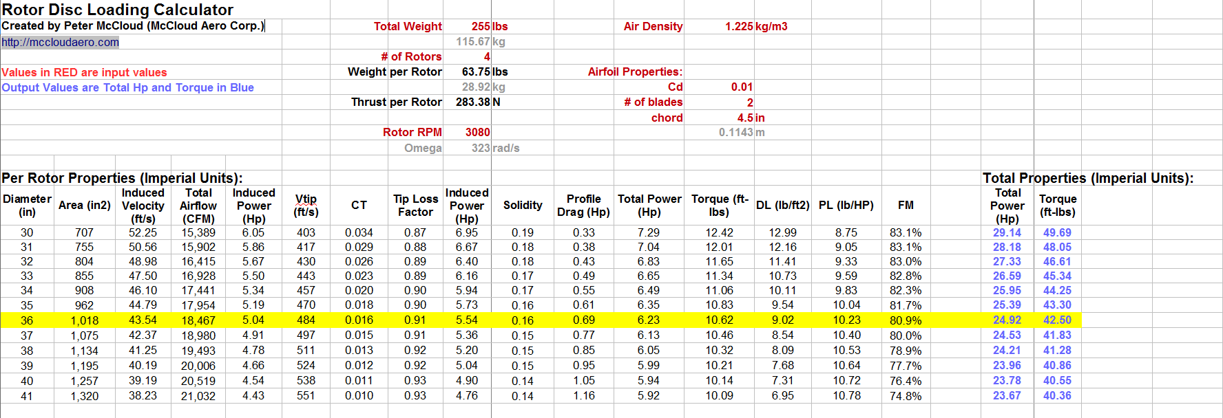
So I've put together a spreadsheet to calculate the power required and I've placed it on github as part of the documentation. The equations are from "Helicopter Performance" by Donald Layton. Inputs are in red and the output is in blue. Essentially you tell it how much lift you need, the rotor rpm, the air density and the airfoil properties, and it spits out how much power & torque is needed. Here's a screenshot of the results for Goliath.
![]() For a fully loaded vehicle at 255 lbs, using 36" diameter propellers at 3080 RPM, 25 Hp is required to hover (assuming standard air density at sea level). This would leave a 5 Hp or 20% margin for climb or maneuvering. This isn't much compared to other quad copters, but Goliath isn't intended to be nimble. Eventually ducting will be added that should help to improve these numbers.
For a fully loaded vehicle at 255 lbs, using 36" diameter propellers at 3080 RPM, 25 Hp is required to hover (assuming standard air density at sea level). This would leave a 5 Hp or 20% margin for climb or maneuvering. This isn't much compared to other quad copters, but Goliath isn't intended to be nimble. Eventually ducting will be added that should help to improve these numbers.One note on the Propeller Figure of Merit (FM) shown in the spreadsheet. This is somewhat equivalent to efficiency. For a vehicle hovering off the ground the efficiency is essentially 0% since you are expending X amount of power to no realized work. Figure of Merit (FM) is calculated by comparing the rotor to an idealized or perfect rotor. For this case Goliath would require a rotor that is 80.9% efficient. A less efficient rotor would require additional power. 80.9% is on the higher side, but it is a doable number.
The last element that needs to be considered is how the power required matches the power produced by the engine. Here is a plot of the power required vs. the engine power.
![]() The required power curve was created by plugging different RPM values into the spreadsheet. Keep in mind that there is a 1:1.1 pulley ratio between the engine and the rotors so that the rotors spin 10% faster than the engine. Thus for a 2800 RPM engine speed, the rotors spin at 3080 RPM. The two curves cross at 2800 RPM, so for a fully loaded vehicle at 255 lbs the engine should run at that speed.
The required power curve was created by plugging different RPM values into the spreadsheet. Keep in mind that there is a 1:1.1 pulley ratio between the engine and the rotors so that the rotors spin 10% faster than the engine. Thus for a 2800 RPM engine speed, the rotors spin at 3080 RPM. The two curves cross at 2800 RPM, so for a fully loaded vehicle at 255 lbs the engine should run at that speed.So can Goliath hover? The laws of physics say it's certainly possible. In reality it's more complicated than that and more data is needed to figure out where things are going wrong. These calculations don't account for belt losses (should be low, but it isn't zero) and bearing losses, but there is 20% margin available. If anyone's interested and feels like checking the numbers or calculations in the spreadsheet, let me know if you find anything. Also if you have suggestions on improvements to the spreadsheet let me know.
In the meantime I'll be moving forward on adding thrust measurements to the test stand!
-
Double Sided Belt Added, First Full Throttle Test
02/16/2015 at 18:43 • 3 commentsIt's officially been a year now since I started putting together Goliath (2/14/15) and I got to start this year out well by doing more testing.
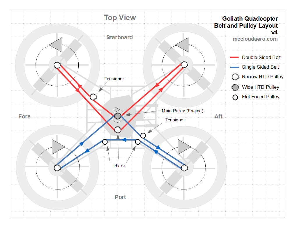
Since the last tests I've ordered and installed the new 30 mm wide double sided belt and installed the new pulleys for it. I've also relocated and redesigned the tensioner for the double sided belt (pulley and tensioner layout). This was to put it in the proper location to take up the slack that develops in the belt.
Relocating this was what took the longest amount of time. I was trying to mirror what I did on the single belt side, but due to the structural layout there isn't as much room and ran into packaging issues. ( I know it's a 10' quadcopter, I really shouldn't have those, but I did)
Here's a top view of the single sided tensioner. The center beams angle away from the tensioner.
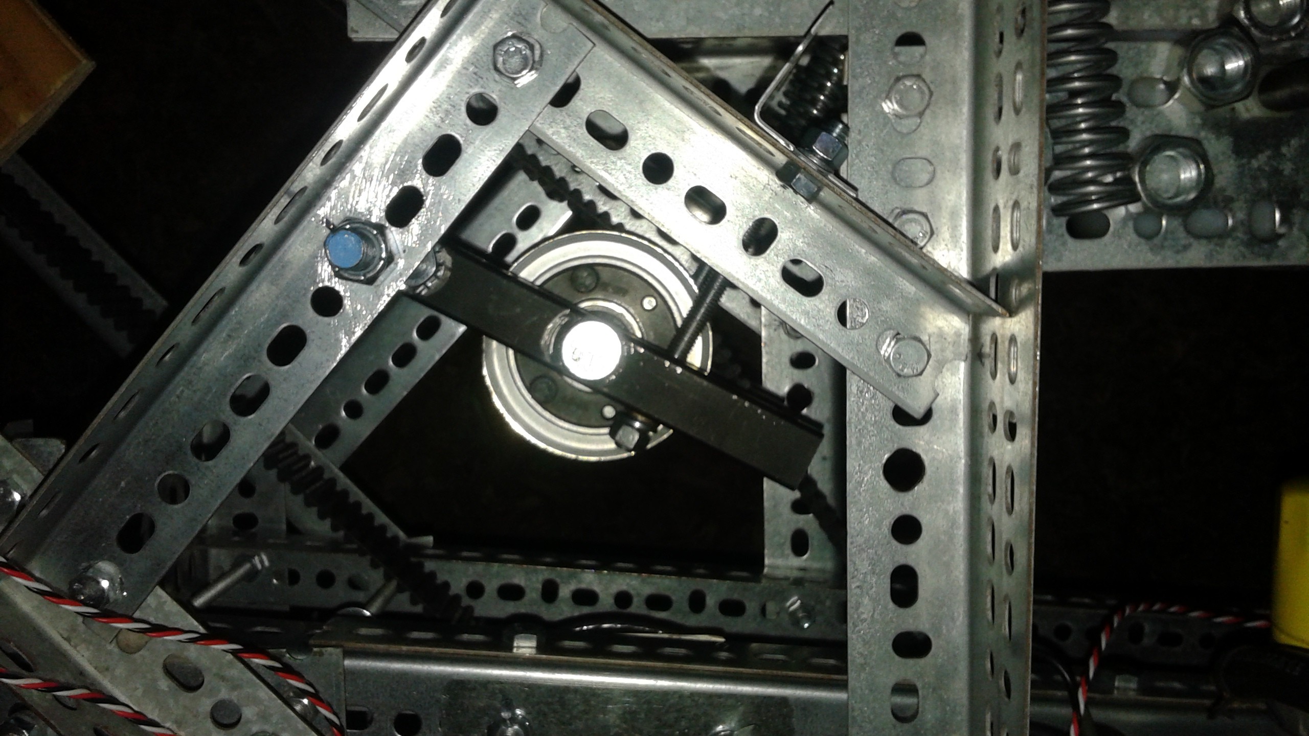
Here's the top view of the double sided tensioner. The center beams angle towards the tensioner. The made it hard to find a good location at the right angle to mount the springs too. Additionally, I didn't have room for the larger springs so I initially downsized the springs.![]()
Once that was in place I finally got to testing. Since the single sided belt testing went well I went straight to testing with the flight props. Here's the video with Tests 17, 18 & 19.![]()
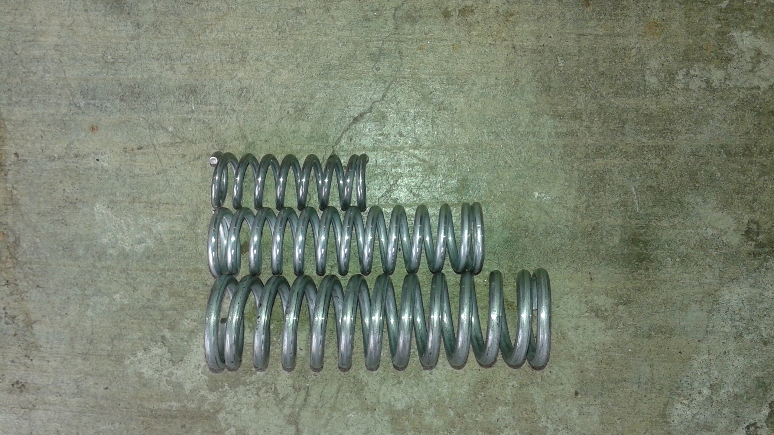
Test 17 went well, but the double sided belts were still seeing a bit of oscillation. I figured this was due to the smaller springs being used. Below is a picture of the different springs I've been using, and the smallest one is the one I used for Test 17. They were shorter and didn't have enough travel to take up all of the slack developing. So for Test 18 I re-arranged the pulleys to get the medium sized springs in the tensioner.
Test 18 definitely showed an improvement to the belts, but I still thought it could be better. I then spent the better part of the day re-arranging pulleys and adding another pulley to allow the tensioner to fit the largest spring. These are the same ones I use on the single sided belt.![]()
So that finally did the trick. For Test 19, Goliath started up and at quarter throttle ran smoothly. After a few seconds to verify that everything was running smoothly, I gave it full throttle.....and Goliath didn't hover....
The great news is that it didn't fly apart. The belts oscillated a bit as it came up to speed, but damped back out at full throttle. The propellers held together as well.
So why didn't it hover?
Short answer, I need more data. Weight is a likely culprit, more hardware was added than anticipated to get the drive system working. Power is another possibility, it could be that the engine isn't providing the required power.
Next step is to get a good weight measurement and add tachometers to determine what RPM the system is achieving. Looking closely at the video there does seem to be some settling as I set it back to 1/4 throttle, so I think I'm getting close.
-
Test #15 and #16 Complete
01/15/2015 at 04:27 • 2 commentsFinally got everything together to start testing again. I'll talk about the last couple of details needed to get Goliath ready after the video. The tests had some hiccups, (nothing was damaged) but it looks like the wider belts are working out better.
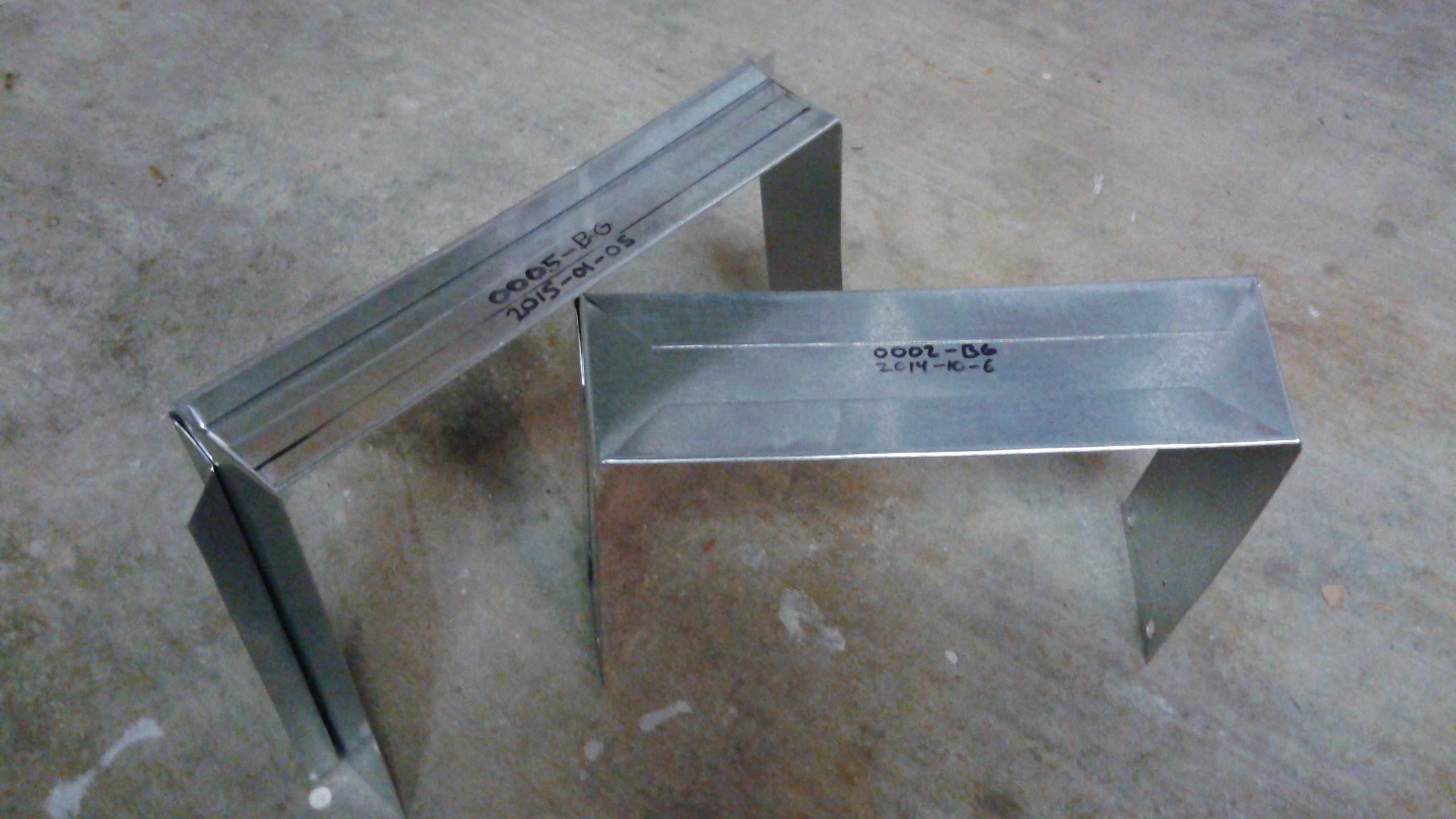
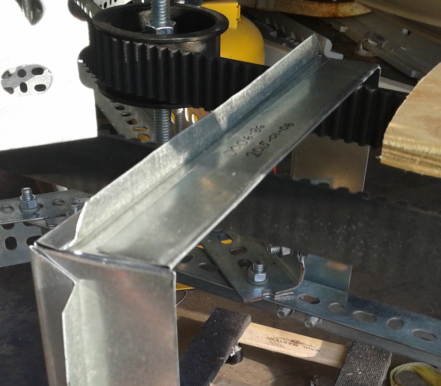
One of the last things needed was new belt guards for the new frame dimensions. I cut a new set, making them 2 inches wide instead of 3 inches. This was because the rotors needed to be placed one notch closer to the engine, leaving a little less room for the belt guard. The second change was to add an extra fold to increase the stiffness.
The new belt guard is on the left and the old one is one the right. Below you can see the tab made with the extra fold to add stiffness.![]()
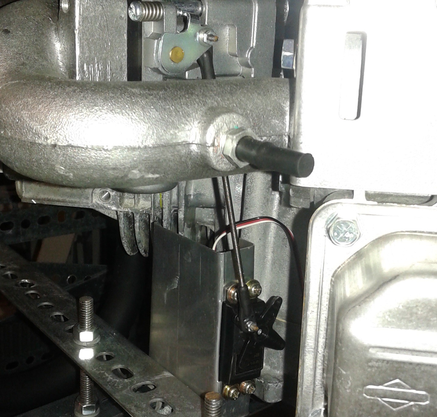
Next, the throttle servo had to be redone. Previously when the servo was mounted, I had to reverse the servo direction on the RC transmitter. This time I mounted the servo with the linkage on the opposite side of the servo so the controls didn't have to be reversed.![]()
![]() With that done it was time to get back to testing.
With that done it was time to get back to testing.So the first test was the one with the hiccups. Since I was using the test props, I figured I wouldn't really need the guy lines to keep Goliath from twisting. The starter obviously provides a lot of torque and caused the vehicle to twist and rock back and forth. The second issue was that part way though the test was that the throttle servo got disconnected. When this happened the engine went to full throttle. Fortunately I was able to shut it off quickly. The culprit turned out to be a missing screw on the servo, (which was obviously missing in the above photo) and the control horn fell off during the test ( below).
I quickly screwed the control horn back on and added the guy lines and did the next test (#16). This time things went well. The exhaust is rattling around and I need to tighten some more screws, but the tensioner is doing what its supposed to be doing now. Since I now the wider belts help, I'm going to place the order for the second belt.![]()
In the meantime I'll be checking things over, coming up with better mounts for the exhaust and likely the throttle servo as well. I'll also need to think about addressing a throttle linkage failure leading to the engine being stuck at full throttle. Seems like a spring or something else is needed to ensure that's not the case.
-
Firmware and Flight Stacks
01/08/2015 at 03:54 • 0 commentsWith the days shorter and the weather colder, I've had some time inside to dedicate towards figuring out the firmware. Early in the project I'd settled on the pixhawk (PX4) controller running the Ardupilot software. My goal was to modify the Ardupilot software to handle Goliath's unique control system. This seemed like a possible path since it had been done previously for the single and co-axial copter.
Now that I've had some time to learn the details of the hardware and related software I have a better understanding of the system and my options. To start with, there is the PX4 hardware. The hardware runs a Real Time Operating System (RTOS) called NuttX. The autopilot software, called a Flight Stack, which actually controls the vehicle, is run by the operating system. What I didn't know before is that in addition to the Ardupilot Flight Stack, the Pixhawk has it's own Flight Stack that the user can choose.
Ardupilot is open source and there is a large development community out there, the documentation for developers is somewhat lacking. Also as @J Groff pointed out, "it's quite a software thicket". It's doable (as demonstrated by the single and co-axial copters), but it'd be a significant amount of work to get the Ardupilot software modified for Goliath. The PX4 Flight Stack however has documentation on getting started as a developer and tutorials for developers to write their own Flight Stack. This seems like a better option, because I can get some simple code working to test Goliath out, and build up the code as Goliath matures. Once I get things nailed down, then I can work on integrating it with the rest of the PX4 Flight Stack.
I've created a fork to the PX4 Firmware and I've started with some basic code based off the tutorials. For now it resides as seprate module, so the code I'm writing lives under /src/modules/goliath_simple. So far I just have some basic logic to start the controller in a startup state (MAIN_STATE_INIT), initialize some variables and look for a valid RC signal. When a RC signal is received then the controller will be switched to another mode. (for now MAIN_STATE_MANUAL). My next steps will be add some basic logic to deal with the ignition and starter relays and to shut off the relays if the RC signal is lost. (This code is primarily meant for the test stand for now, so I want to make sure thing shutdown if I can't communicate with it.)
Things are still coming together on the actual hardware, hopefully just a few more items and it'll be back to the test stand to test out the changes.
-
Belt Upgrade: Frame Reconfigured
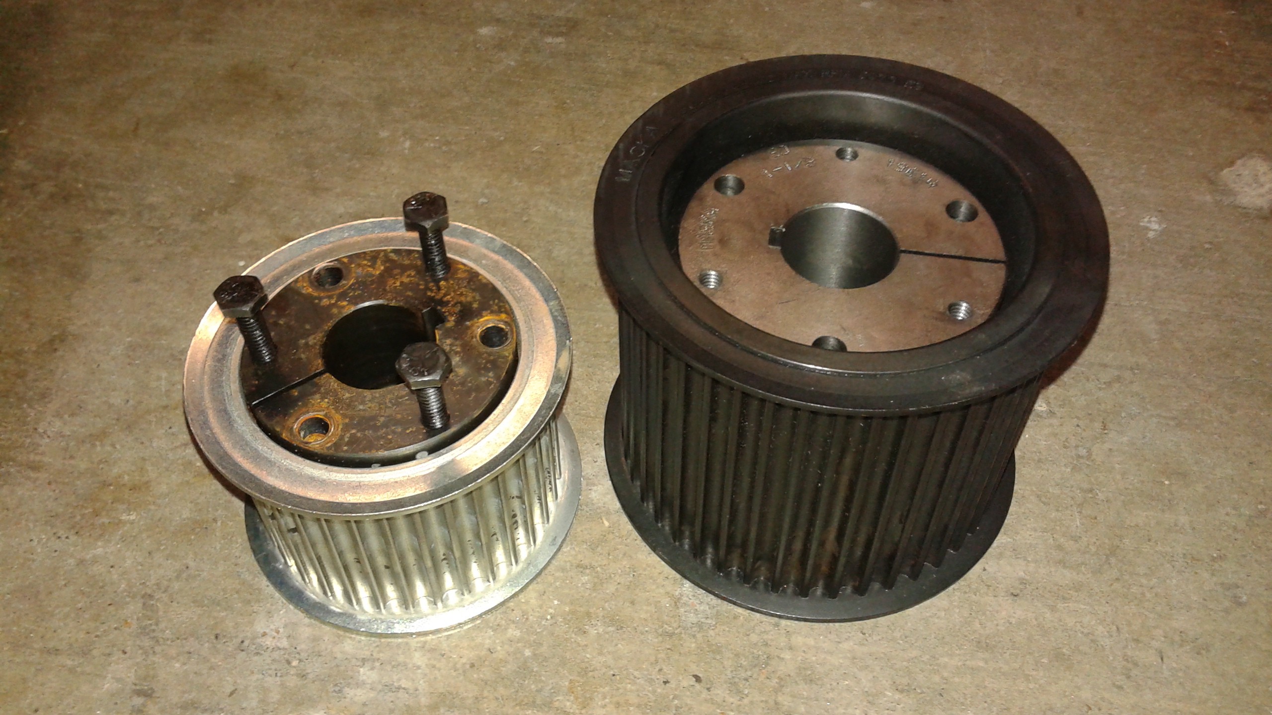
12/27/2014 at 16:28 • 0 commentsCurrently I'm working on upgrading the belts on Goliath from 20 mm to 30 mm wide. Most of the hardware arrived a couple of weeks ago and I've been working on getting things installed. Below are the new and old prop pulleys with the ball bearing bushing. Both pulleys take SH Quick Disconnect (QD) Bushings, so I can reuse the same bushing.
HTD 8mm pitch pulleys come in standard widths of 20, 30, 50 and 85 mm. Since the center pulley needs to accommodate two belts, the center pulley needed to be 85 mm wide. Below is the old and new center pulley with bushings. The new pulley required a bigger SD size bushing so a new bushing was needed.![]()
![]()
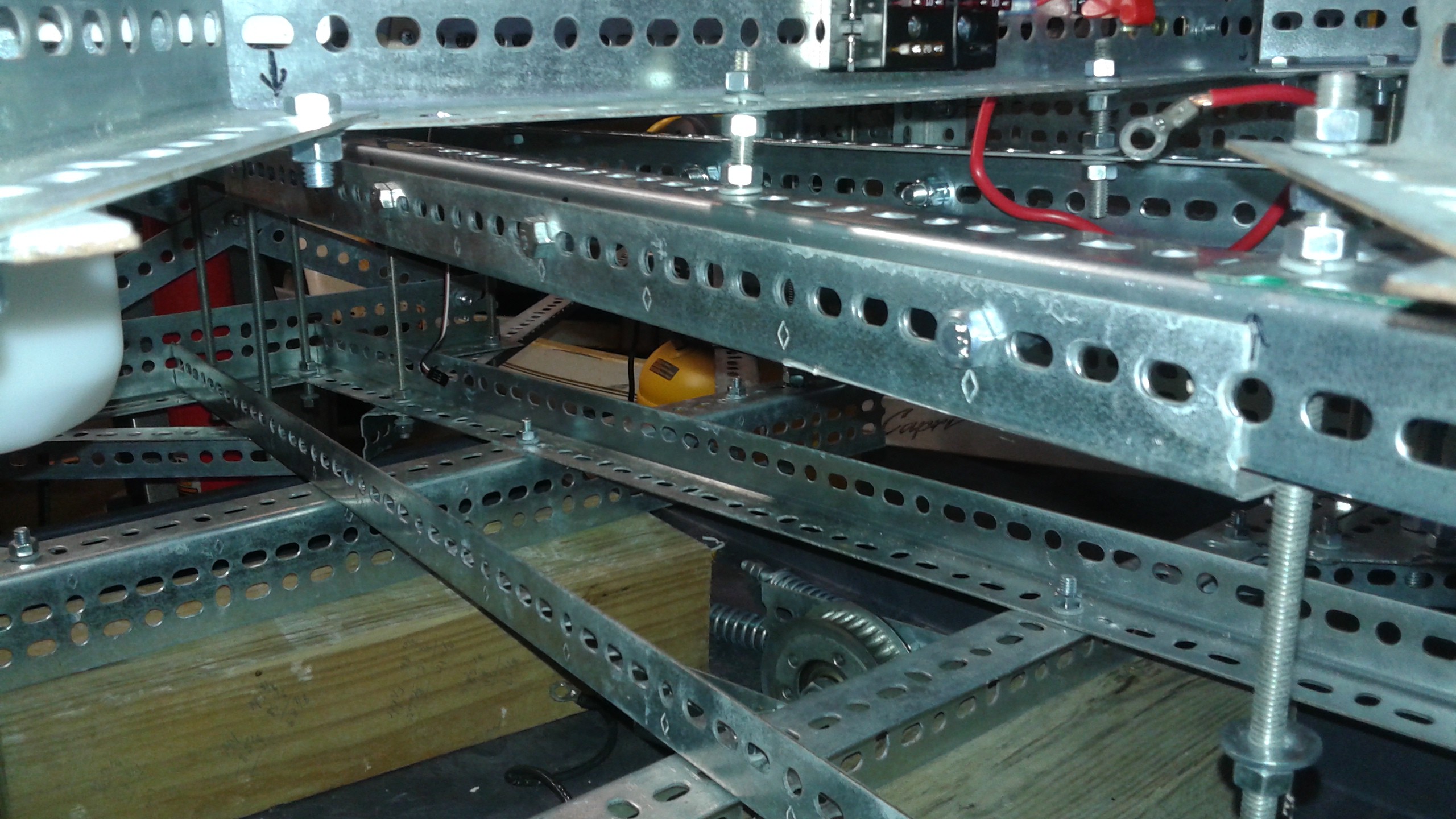
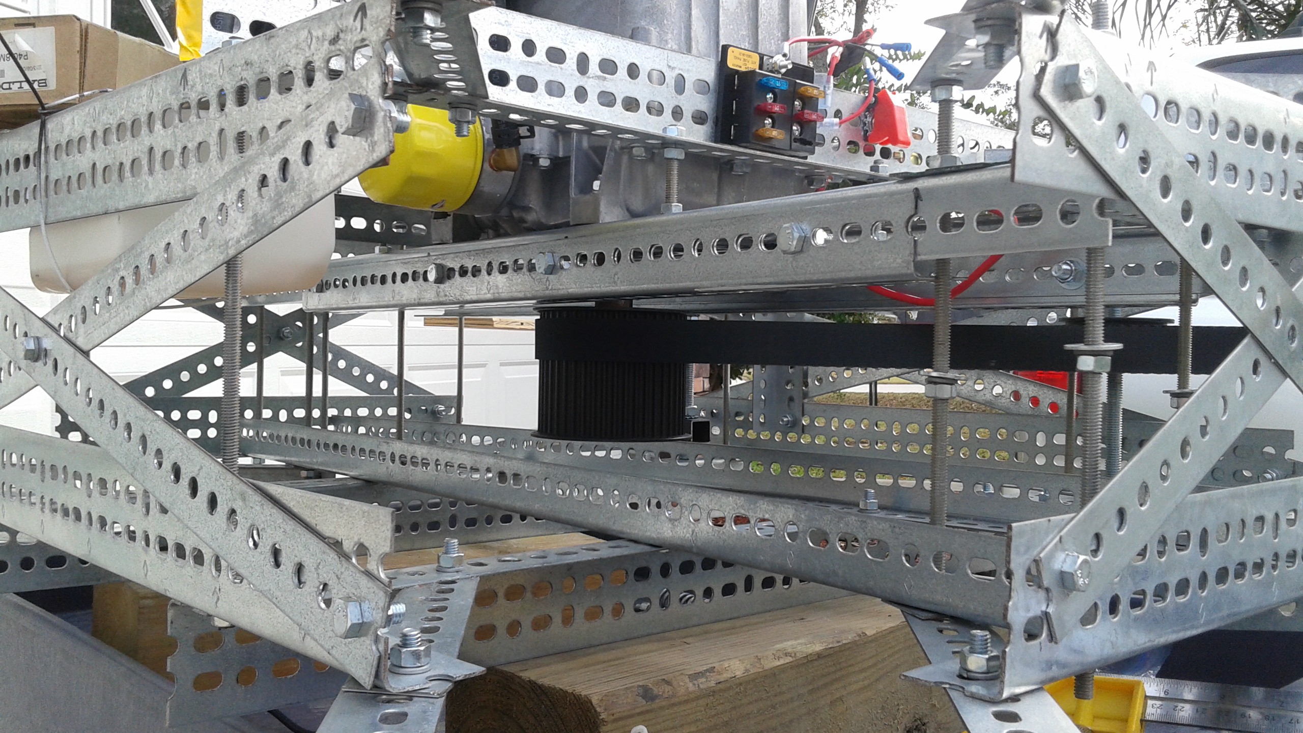
A critical difference between the two pulleys is that for the the new pulley, the bushing is recessed and the top of the pulley sits above the top of the bushing. This means that the upper belt is closer to the engine. This was an issue since there was barely enough room previously between the upper belt and the center beams that the engine sits on top off. To make room, the engine had to be removed and the wide slotted angle replaced with narrow slotted angle.
I was concerned that the narrow slotted angle wouldn't be stiff enough so I bolted a second narrow slotted angle to it to form a c-channel. To save some weight, the second piece only covers the primary span and none of the all thread runs through it. This means I can remove it easily if it proves to be unnecessary.![]()
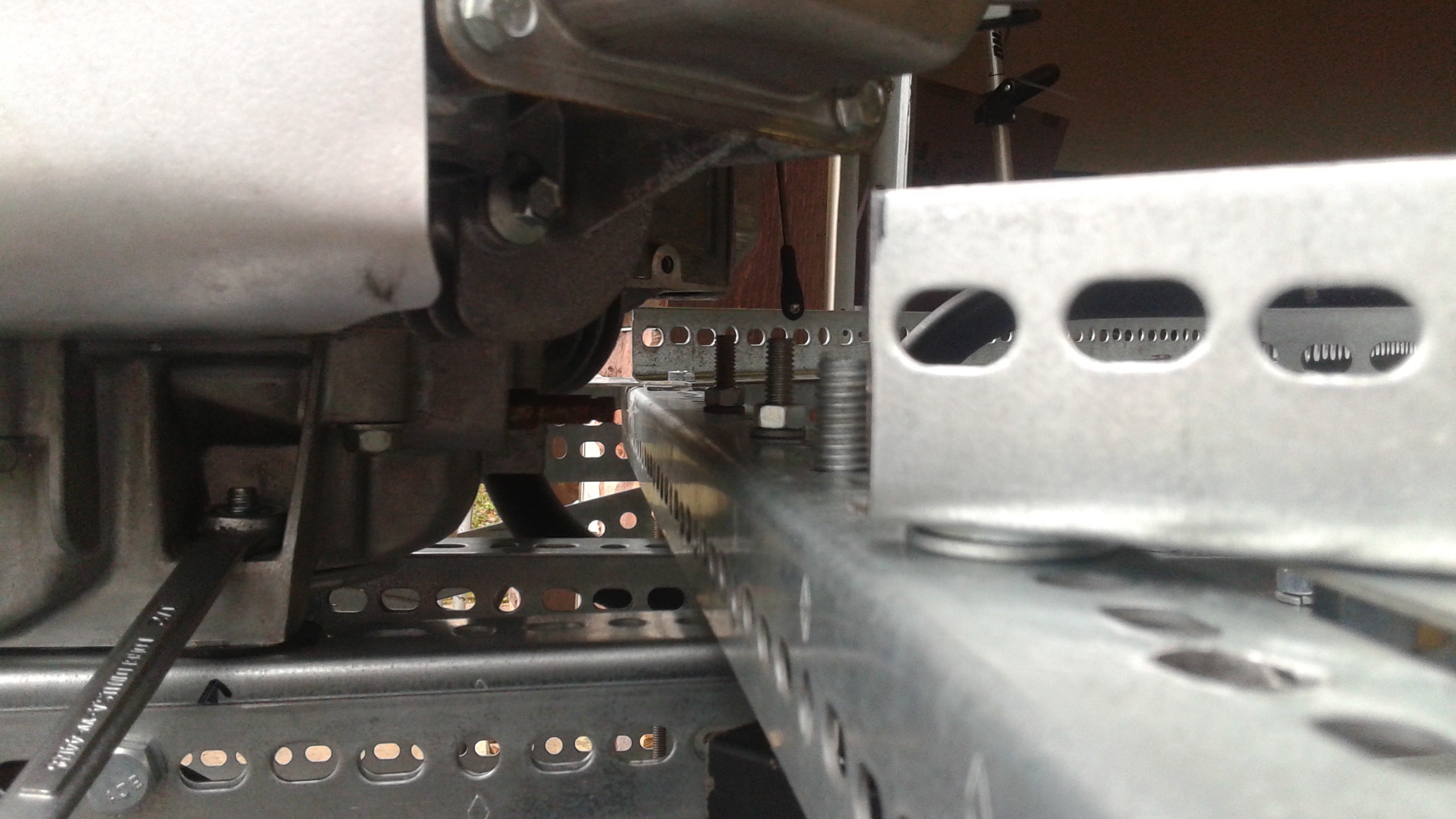
Next, the top of the center pulley had to be aligned with the rotor pulleys for the upper belt. The center beams already sat 1" below the top of the frame, but it had to be lowered another 3/4" so that the the pulleys were lined up. This part was a lot easier to do with the all thread construction. However the the cross beam that sits underneath the cylinder covers was in the way. It was a wide slotted angle piece, but after lowering the engine, there wasn't clearance for a narrow slotted angle. The solution was to flip the narrow angle over so that it pointed downwards.
![]()
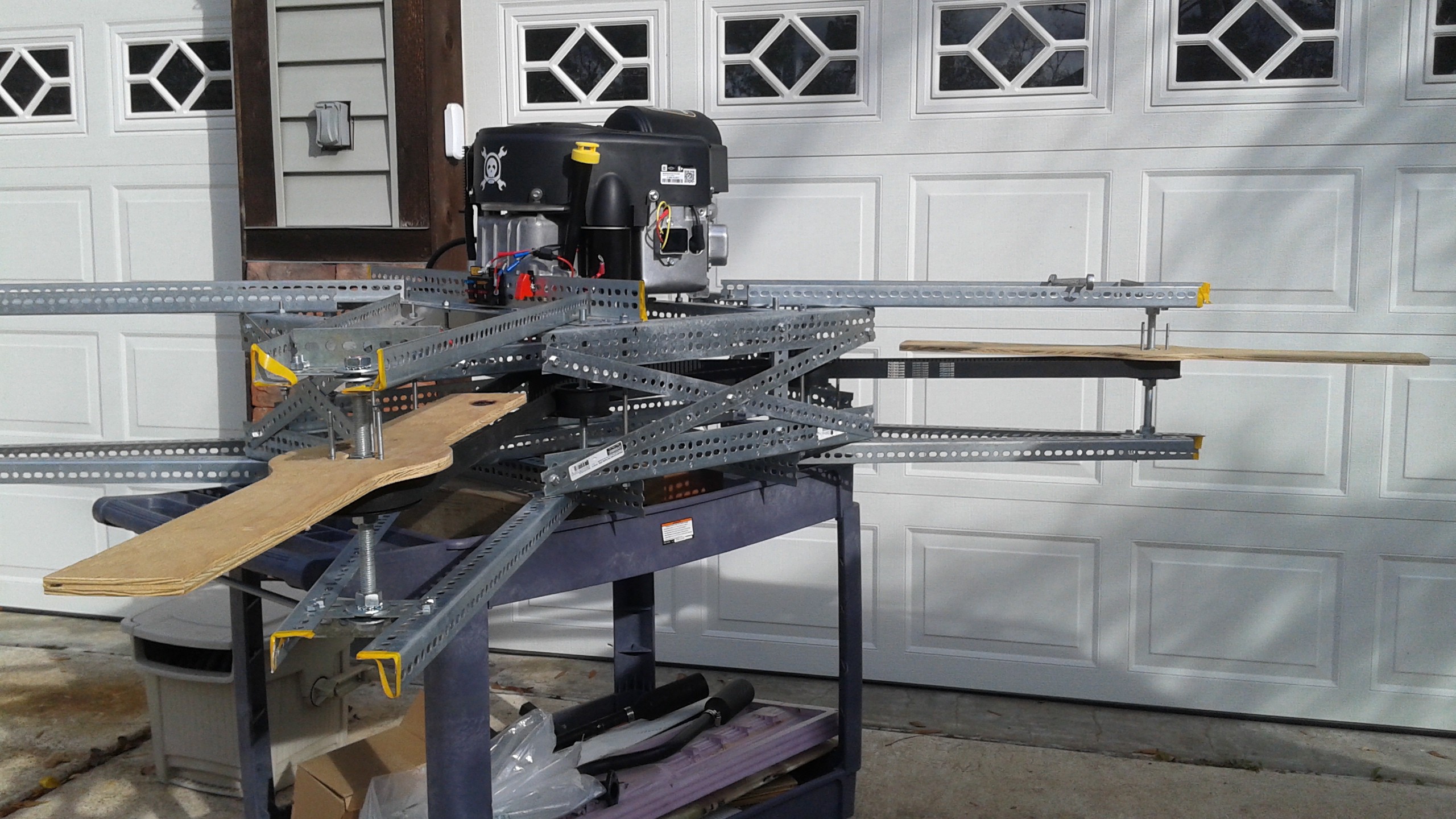
With the upper portion of the frame completed, the remaining modification was to make the whole frame taller to fit the center pulley between the cross members. This meant increasing the space between the decks about 1". While I had left some excess length in the all-thread to allow the frame to be expanded like this, it was somewhat fortuitous that I chose the length I did because it was just barely enough.
As you can see, there isn't much excess room. Here's another shot to give you an idea of how Goliath as a whole looks now with one of the belts installed.![]()
![]() I think the changes to the frame are complete. The next steps are adjusting the pulley layout to account for the larger diameter pulleys and placing the tensioner on the slack side of the belt.
I think the changes to the frame are complete. The next steps are adjusting the pulley layout to account for the larger diameter pulleys and placing the tensioner on the slack side of the belt. -
Tachometers
12/17/2014 at 14:27 • 7 commentsI've received the new pulleys and I'm in the process of swapping out the hardware. I'll get more into the details in my next project log, but to make everything line up correctly, I'm having to adjust the frame and had to pull the engine off to do it. More details to follow.
I've been thinking about the latest testing where some of the tests ended and the rotors were no longer aligned with each other. This is due to the belts skipping teeth. The new belts and pulleys should help prevent this from happening, but it'd be good to have a way of monitoring the speed/position of the engine and each of the rotors. Tachometers measure rotational speed and rotary encoders measure the rotational position, but I think I can use a a tachometer placed on the support arm at each propeller to measure the speed and then compare the signals to tell if they are in sync or not. This information will also be useful to have available to the Pixhawk to provide some closed loop control of the gas engine.
From doing some research it doesn't seem straight forward (or maybe possible) to have the Pixhawk directly measure the rotational speeds. Long term, the ideal setup would be a Gas Engine Control Unit (ECU) that would have at least (5) tach sensor inputs on it, relays for the starter and ignition, a simple processor for computing the actual speeds and an I2C interface to talk to the Pixhawk. (The overall concept of having a breakout board that interfaces with the Pixhawk over I2C is similar to the PX4FLOW board)
As far as the actual sensors go, typically hall effect or optical/IR sensors are used. I'm leaning towards using IR sensors mounted above the rotors on the support arms, so they will only be a couple inches away. If I did a hall effect sensor I'd have to add a magnet to the rotors. There's some good instructions on instructables by [electro18] using IR sensors. I'll probably start with these sensors , but use the Raspberry Pi I have on hand and work forward from there. I likely won't get started on this until I get Goliath back together and running again.
Since electronics is not what I usually do, if anyone has any thoughts on this I'd love to hear from you.
-
Roller Chain vs. Belt Drive and New Belts
12/06/2014 at 01:53 • 0 commentsThe last time I wrote I was getting ready to add additional pulleys to try to deal with the belt oscillations. Over the Thanksgiving break, I had some time to think about it some more and came up with some alternatives. One of the first things I did was go back to the initial design guides I used to decide whether or not to use belts. I decided this time to take some time to create a graphic that illustrates the the design space between roller chain and belts.
![]()
The graphic above shows the maximum power capabilities for both Roller Chain and High Torque Drive (HTD) belts. While I've only plotted British Standard Chains (vs ANSI), the properties are the same. The three curves for chains show simplex, duplex and triplex (one, two and three strands). The different points called out are for the different chain sizes (05B being the smallest to 32B the largest) For belts, three different pitches of HTD belts are also shown.
The graphic shows that at lower RPMs, roller chain has a far superior power capacity than HTD belts. As the RPM increases, the maximum power capability of roller chain decays exponentially, in contrast the HTD belt power capability increases. Above 1000 RPM, 14mm pitch have the most power capability and above 1200 RPM, 8mm pitch HTD belts are superior in power capability than roller chain.
Also plotted is the point where Goliath operates, with a maximum power of 30 Hp (22.37 kW) at 3600 RPM. However, when designing a power transmission system a service factor has to be applied. In this case I choose a service factor of 2.3. This means that the belt system should be designed for 51.5 kW at 3600 RPM. This is clearly well beyond the capability of roller chains.
So back to what needs to be done with Goliath. Over Thanksgiving I decided that it'd be appropriate to upgrade the belts from 20 mm wide to 30 mm wide. This would give a belt that is 50% stiffer and help reduce the oscillations. I also revisited the design guides and a 30 mm wide belt would be able to withstand the worst service factor listed (2.3). Since a 30 mm wide belt requires new pulleys, I'm also going to get larger diameter pulleys (40 teeth vs. 32 teeth). This will increase the power capacity and help prevent any teeth from skipping.
So I've ordered the new pulleys and a new single sided belt. The hardware should be here early next week. I'll test things out with just the single sided belt, and if that works then I'll order the more expensive double sided belt. If the bigger belts still have oscillation issues, I should at least be in a better position when I start adding more pulleys.
-
Testing Belt Configurations (Tests #11 - #14)
11/26/2014 at 04:43 • 0 commentsLast week I was able to test out some new belt configurations. After checking out the test stand in tests #9 and #10, it was clear the test stand was working well, but the belts were still having issues. It's apparent that the flight rotors require a lot more torque than the test rotors and there is more slack in the belts due to this.
The first attempt (Test #11) was adding a pulley on the slack side of the double sided belt. It seemed to help a little bit, so the next attempt was to try tightening the belts a little bit. This did not improve the situation. The literature suggests that having the belts too tight is as bad as having them too loose. This is because if the belts are too tight, the pitch on the belt gets stretched and they no longer mesh well with the pulleys. I don't know if that's what happened during the test, but after the test was over, the two sets of propellers were no longer aligned with each other.
Another potential issue was how well the props were balanced. I hadn't balanced them thinking that they were probably close enough and the weight of the propellers was less than the pulleys. After Test #12 I took the time to balance the propellers. Only two of the propellers needed any weights and those two didn't need very much. I'll do another write up on balancing the props later. However after balancing them and running it, there was no perceptible change. The last change made was removing the springs on the double sided belt tensioner. I was curious as to if the springs were contributing to the oscillations. Again, no visible changes in the oscillations.
So overall thoughts on testing so far.
- The frame does not flex significantly like it used to. Some of this has to do with the way it was tied down before, but some of it also has to do with the changes to the frame that have been made.
- The flat idlers are working. This are significantly lighter than the steel HTD pulleys.
- While the belts are moving around significantly horizontally, they are staying in place vertically. Those parts of the issues seem to be solved
- The relay board is working well. I was concerned with using mechanical relays with this amount of vibration, but so far they've worked.
So far the overall design philosophy has been to use the minimum number of pulleys. This was to come up with a minimum weight design. It's clear that the minimum number of pulleys are not sufficient. Luckily the design so far is underweight, so some additional weight can be absorbed. The next steps are to add more pulleys to help dampen the oscillations and likely move the tensioners to the slack sides of the belts, again to help dampen the oscillations. -
Tests #9 and #10, Checking out the Test Stand
11/16/2014 at 17:19 • 2 commentsWell the rain held off on Saturday long enough to do some short tests in the new test stand. Most of the morning was setting up all of the tie-downs. There are 8 lines supporting Goliath's weight. Two on each of the prop supports for redundancy. Eight lines are connected horizontally, two on each prop arm. Again there is some redundancy built in, so if a line fails or comes loose, the vehicle will still be secure. Underneath Goliath are four lines, each with about 3" of slack. These will come into play when doing to the hover test. Once Goliath has enough thrust it will lift upwards 3" until the lines are taut.
![]()
In addition to the test stand, there is a protective barrier setup (a sheet of plywood with a hole cut into for a camera to take video (nicknamed the bunker).
Two tests were run yesterday. The first, Test #9, was run for a short bit to check out how everything worked. We only took video from behind the bunker for this test. The belts seemed to have more oscillations in them than previous tests. This was not obvious from the video, but could see it from my vantage point. So I tightened up the tensioners and added a forward camera view and ran Test #10. Again the cameras didn't catch the oscillations, I need to get a better vantage point.
It could be that the wood dummy props were balanced better. I'm going to remove the props and balance them while they are attached to the pulleys to see if that makes a difference. The new flat belt idler seemed to hold up, so I'll probably switch out the other pulley were I can put a flat belt idler and move that HTD pulley to act as an idler on the double sided belt to try to dampen out the oscillations.
Overall the tests show that the test stand works well. Even though there is some give in the lines, the vehicle isn't bouncing all over the place. This setup should also work well for evaluating the controls once those are added on.
-
Test Stand (The Octagon!)
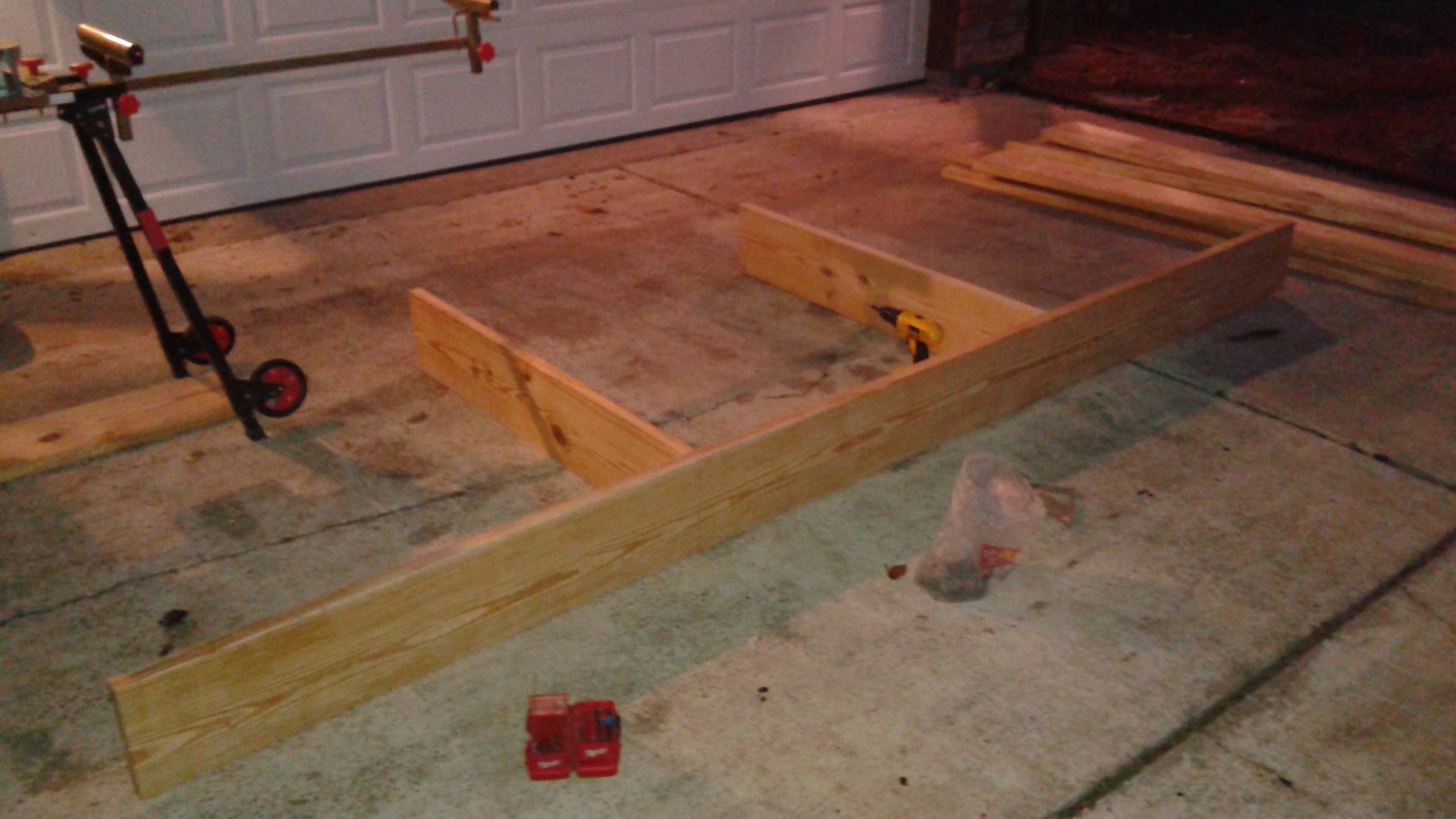
11/12/2014 at 04:37 • 0 commentsAfter going back and forth on how to rig up the hover test, I decided to go with a large test stand that will enclose Goliath. I've nicknamed it The Octagon cause it has eight sides and saying The Octagon reminds me of Rex Kwon Do from Napoleon Dynamite.
Anyways, I started building the stand Sunday night out of 2x10s in the driveway. It's split into two halves to wrap around Goliath. Below is the top of the first half.
![]()
After this it was tipped on it's side and the legs were added.
![]()
Here are both halves of the initial frame.
![]()
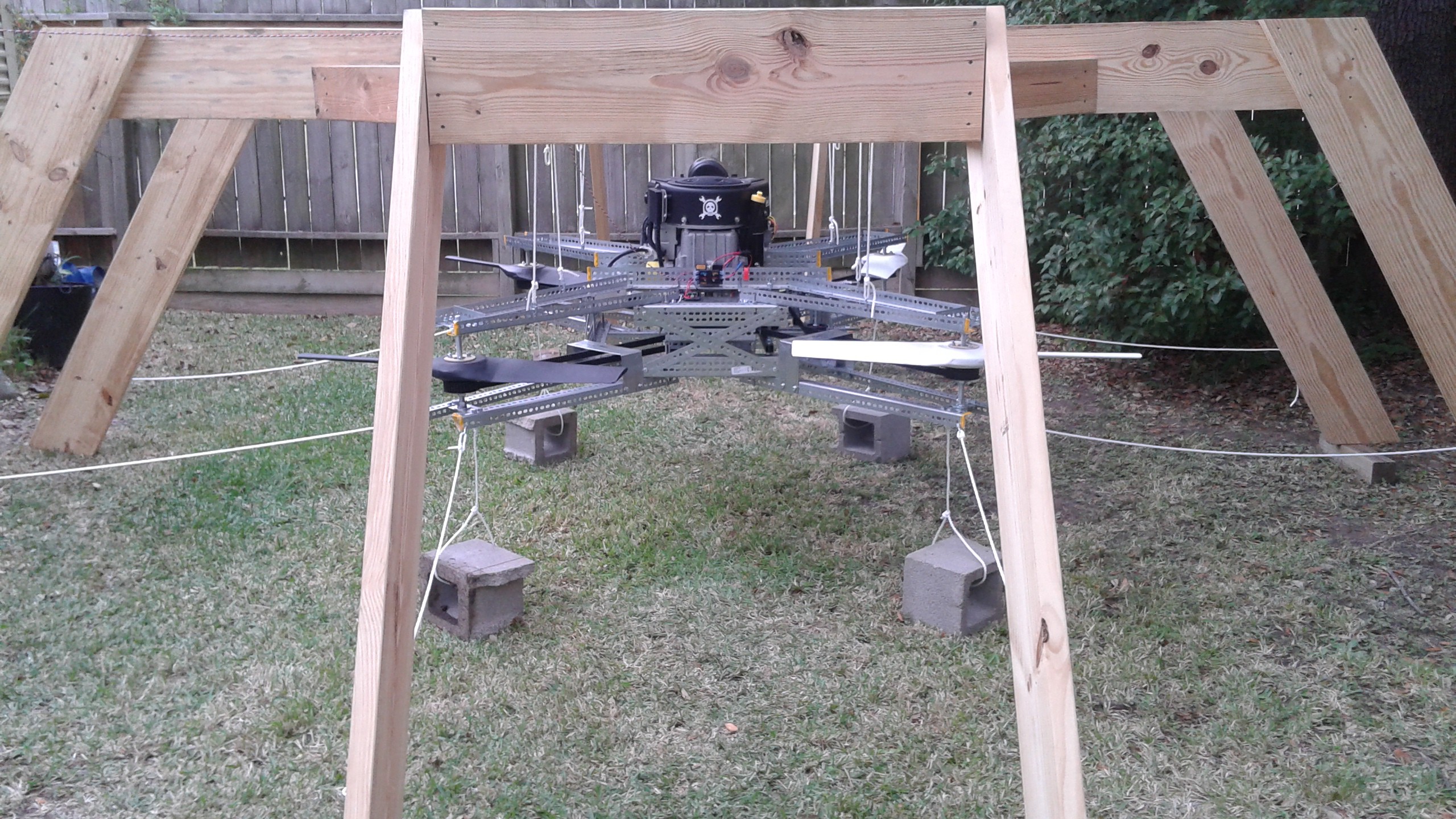
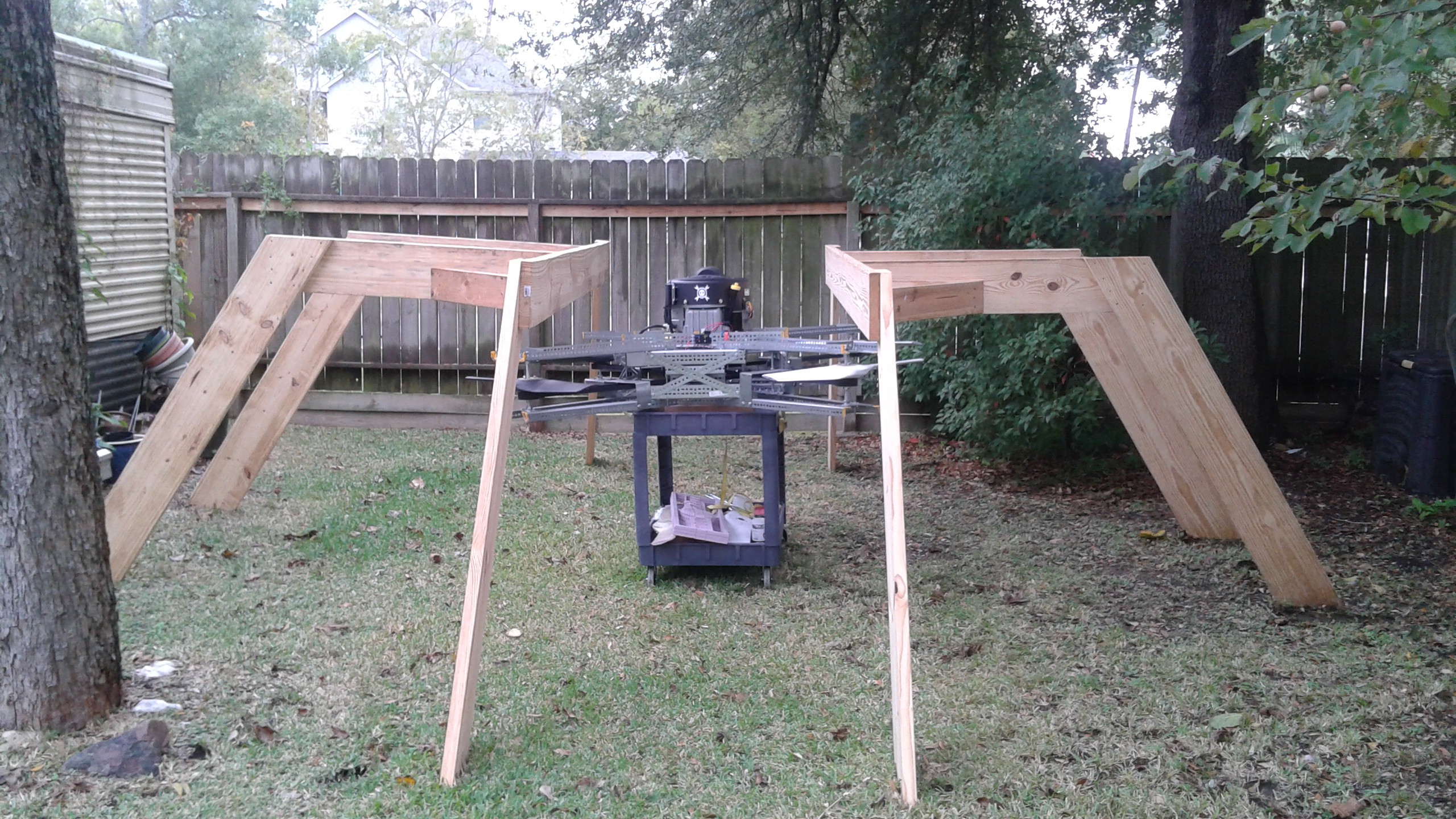
I had today off for Veteran's Day and got started on actually setting up Goliath in the stand. I moved the frame to a spot in the backyard that's surrounded by a fence on two sides and a building on the third. This should help to contain any debris contained for the higher RPM testing.
![]()
The next steps were leveling the stands and joining them together with some more 2x10s. Using some rope, eye-bolts and s-hooks, each arm was lifted up to take the weight off the cart.
![]()
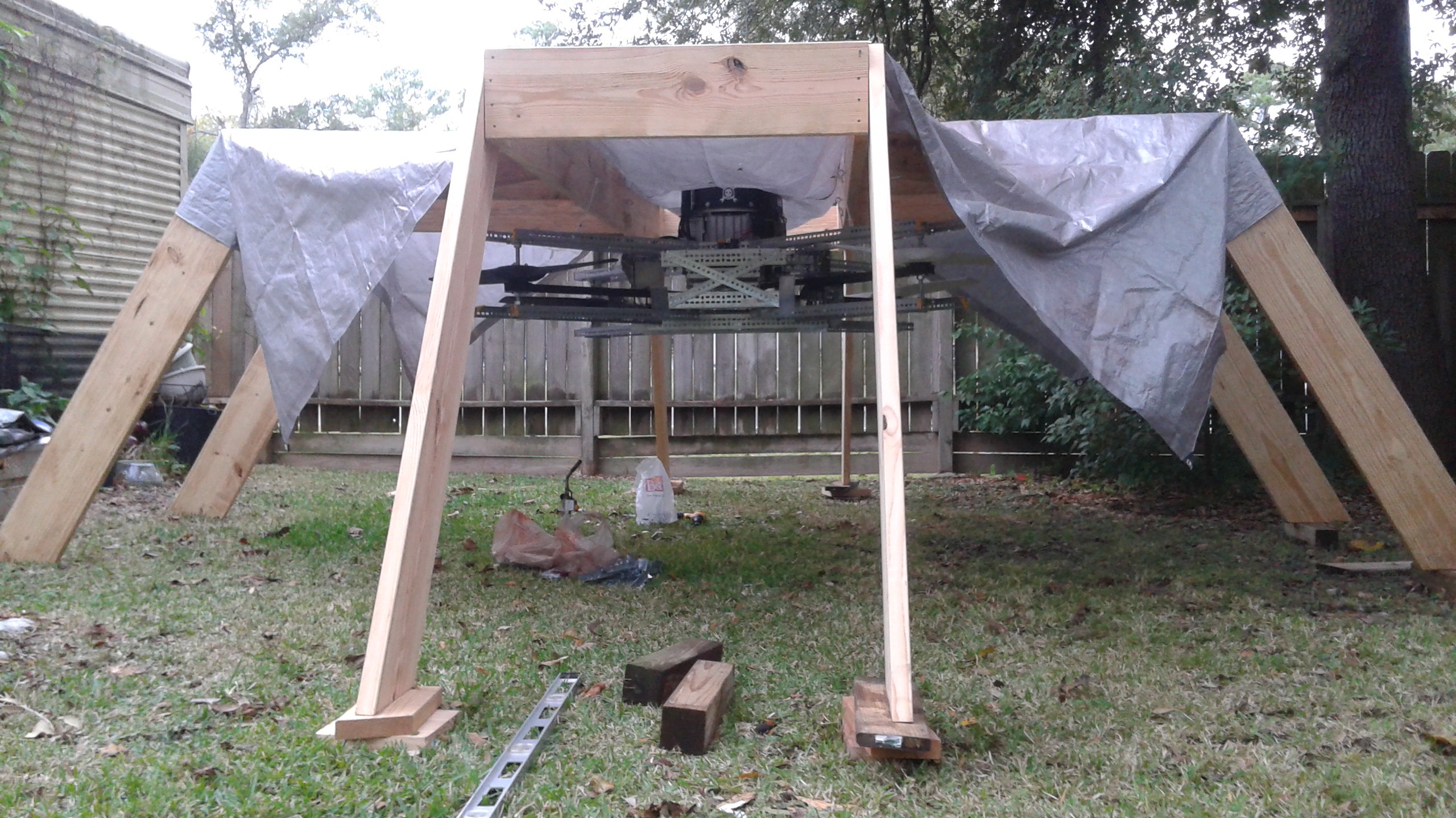
It's been raining a little bit and it'll be a couple days before I have some time to do more testing, so Goliath will have to stay in the stand and be covered up.
![]()
Here's a shot underneath the tarps. I've also wrapped the engine and electronics in plastic to make sure any leaks.
![]()
The next step will be lowering it a foot so that it has 2 feet of clearance above and below. Then I'l add two tie-downs to each corner to prevent Goliath from twisting.
When the hover test happens, the plan is to have four ropes tied to Goliath underneath and attached to cinder blocks. Each rope will have a couple inches of slack (all the same amount). As the engine speed increase, the weight on the test stand will decrease and when the thrust is finally greater than the weight, the slack in the lower lines will be eliminated and we'll know if we've had a successful test.
Like I mentioned, the weather's kinda crummy right now, so no date set yet for the next tests, but stay tuned!
 For a fully loaded vehicle at 255 lbs, using 36" diameter propellers at 3080 RPM, 25 Hp is required to hover (assuming standard air density at sea level). This would leave a 5 Hp or 20% margin for climb or maneuvering. This isn't much compared to other quad copters, but Goliath isn't intended to be nimble. Eventually ducting will be added that should help to improve these numbers.
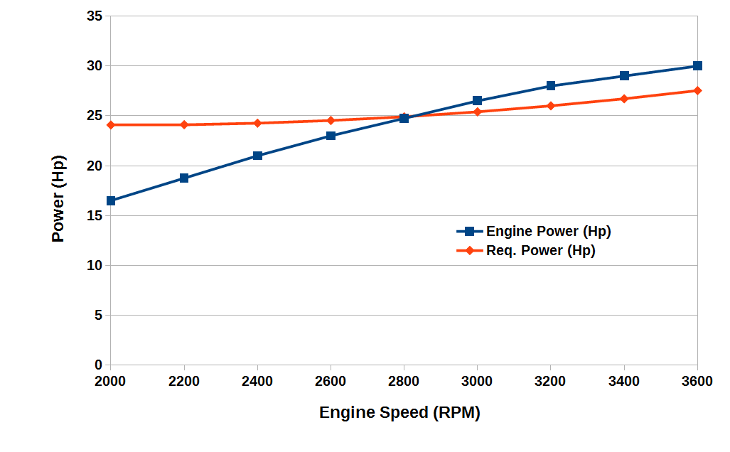 The required power curve was created by plugging different RPM values into the spreadsheet. Keep in mind that there is a 1:1.1 pulley ratio between the engine and the rotors so that the rotors spin 10% faster than the engine. Thus for a 2800 RPM engine speed, the rotors spin at 3080 RPM. The two curves cross at 2800 RPM, so for a fully loaded vehicle at 255 lbs the engine should run at that speed.
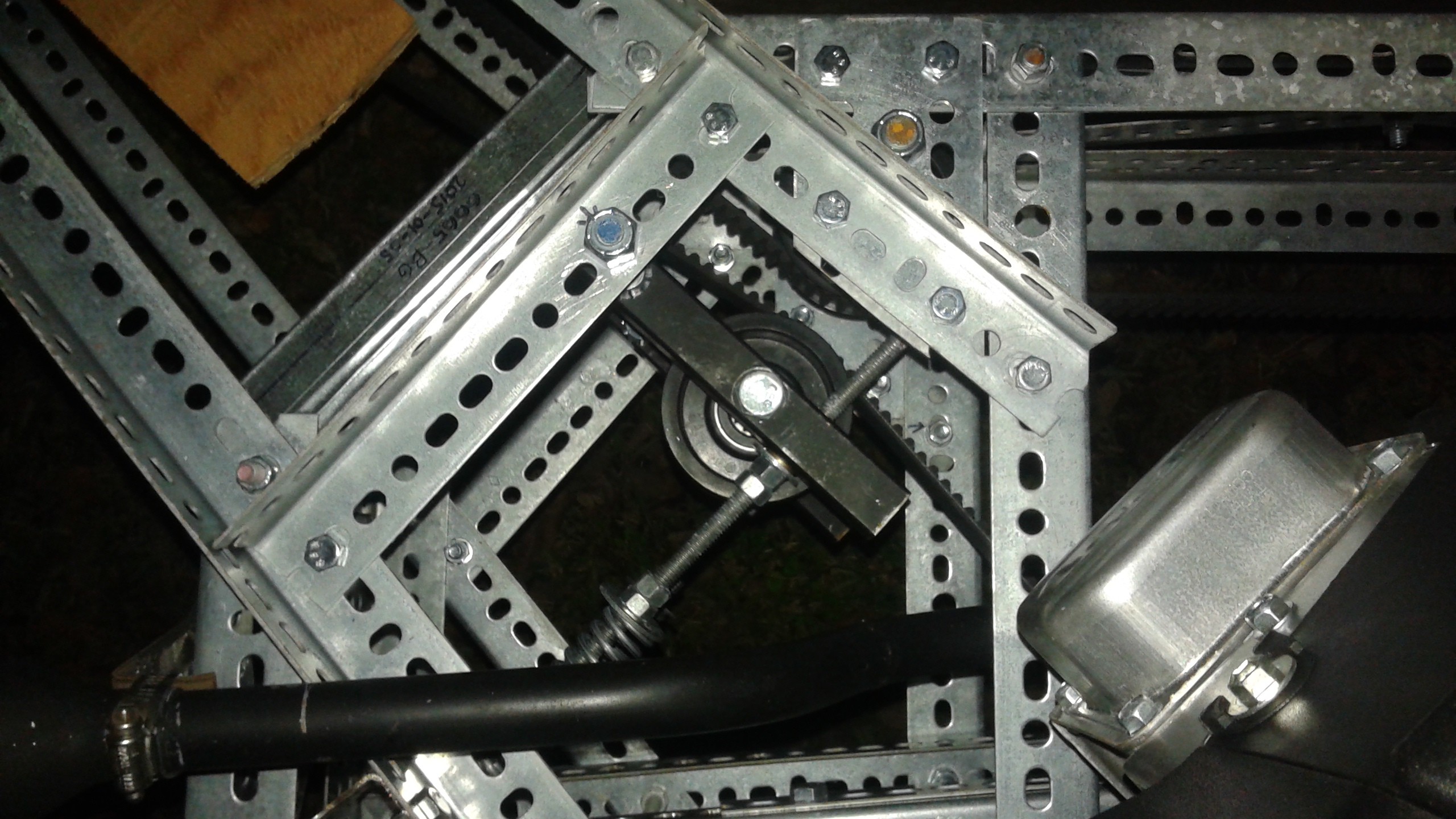
 With that done it was time to get back to testing.
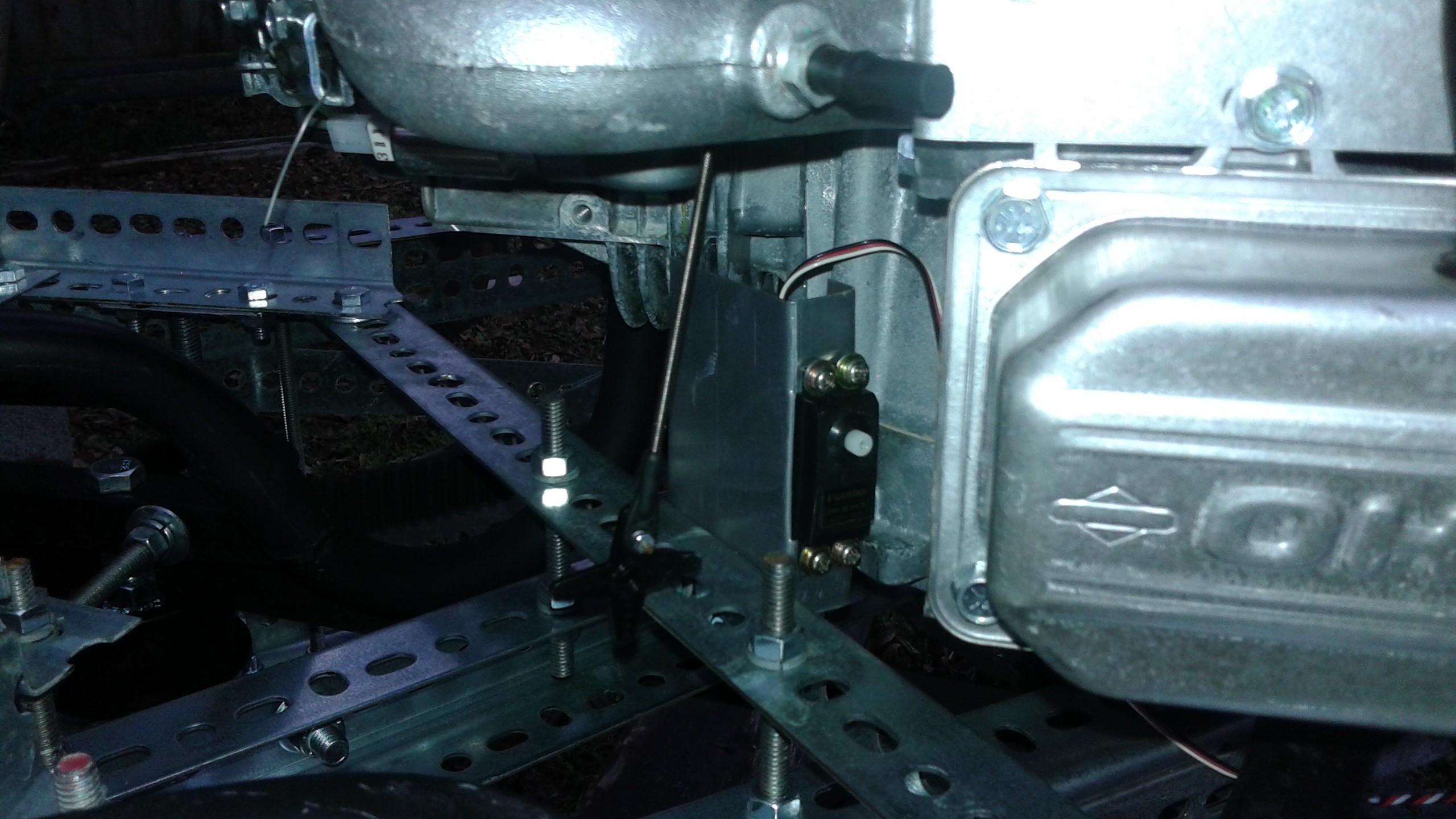

 I think the changes to the frame are complete. The next steps are adjusting the pulley layout to account for the larger diameter pulleys and placing the tensioner on the slack side of the belt.
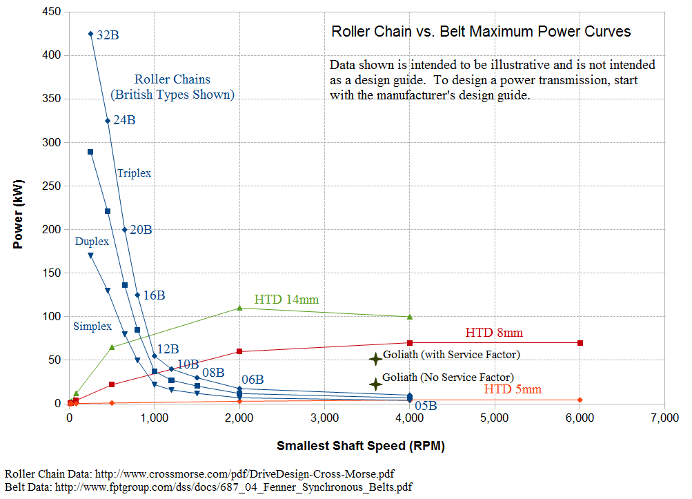


