Peter McCloud
-
Mini Maker Faire Summary, Propeller Project and other Progress
11/08/2014 at 15:57 • 0 commentsThe Houston Mini Maker Faire last weekend went well. Thanks to everyone who stopped by. We spend the entire time answering questions. I was amazed at how many Hackaday readers came by and said hi. We have some pictures from the event here. If you have any pictures, we'd love to see them. Houston Mini Maker Faire
Another thing I've been working on is documentation on the propellers. I'd struggled during The Hackaday Prize on how best to document the propellers as part of Goliath. I finally decided that the best way was simply to have a separate project log for the propellers. So if you're looking for details on the propellers, check out Inexpensive Composite Propellers/Rotors (Project 3221). Like Goliath it's still a work in progress.
Now that I don't have the time crunch with The Hackaday Prize, I can take take a bit more time to fix some things. One thing I'd been meaning to fix was the starboard exhaust pipe. I'd initially made a mistake welding it together and placed it on the wrong side of the bracket. Later the problem was compounded when I lowered the engine an inch. This made it more obvious that there is a height difference between the two cylinders (3/4" to be exact). This made it so that the starboard exhaust pipe vibrates against the frame when running the engine, something that should be taken care of before I run the engine too much more.
To fix this I ground off the old weld, cut 3/4" off the pipe and tacked the flange back on. I tripled check the fit this time, finished the weld and I'm in the process of repainting the exhaust.
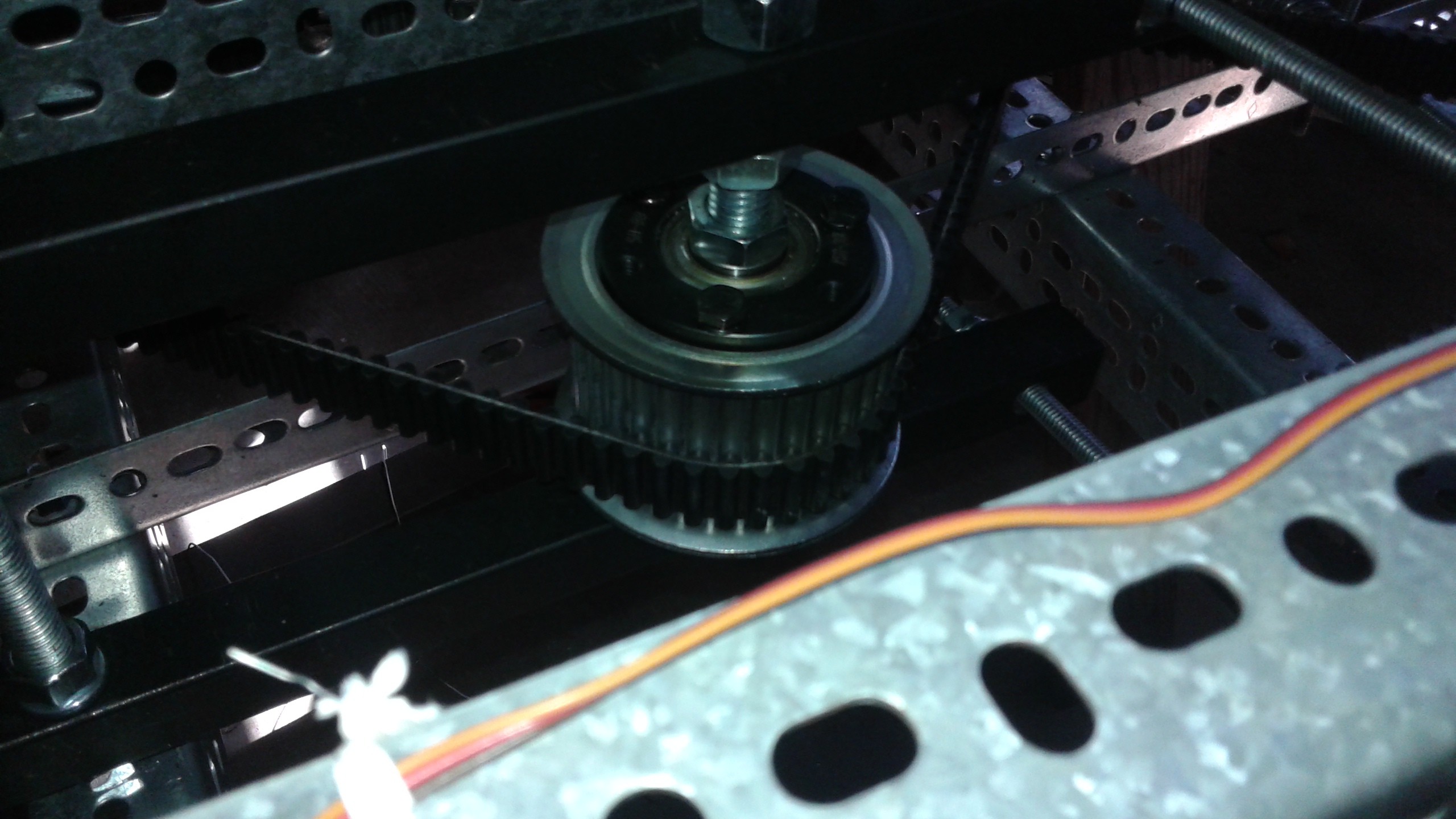
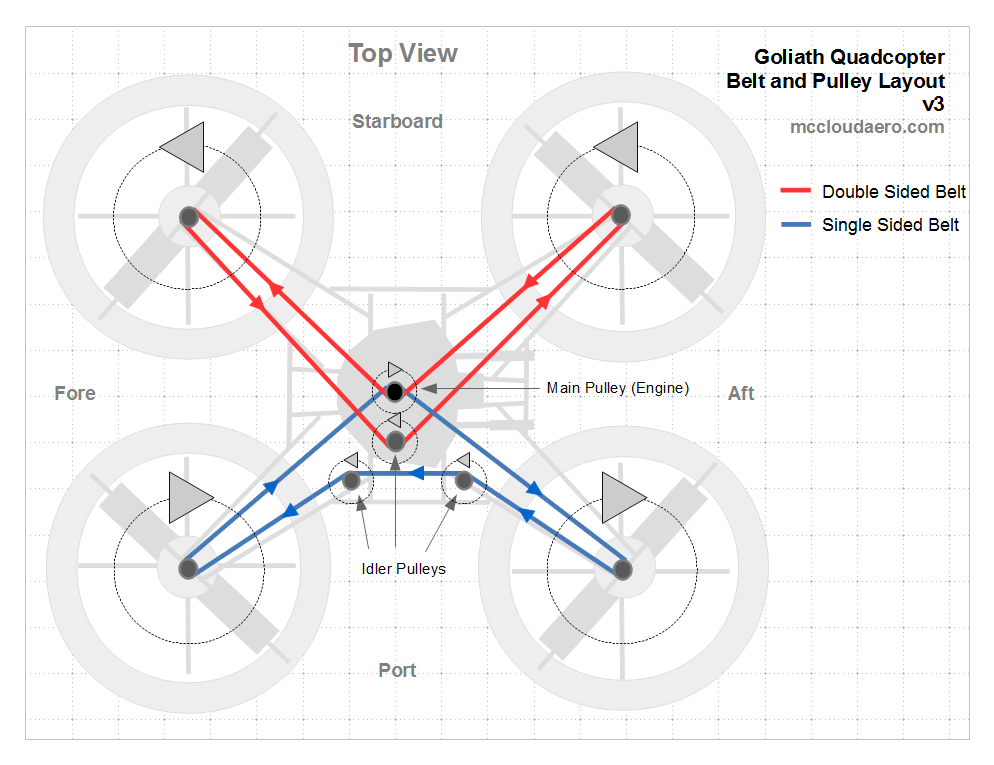
The pulleys have been reconfigured by replacing one of the toothed idlers with a flat belt idler. This is a nylon pulley instead of steel, it's lighter, but I'm not 100% confident it's really going to work well, but that's what testing is for. If this doesn't work I'm going to have to see about making some custom idler pulleys.
![]()
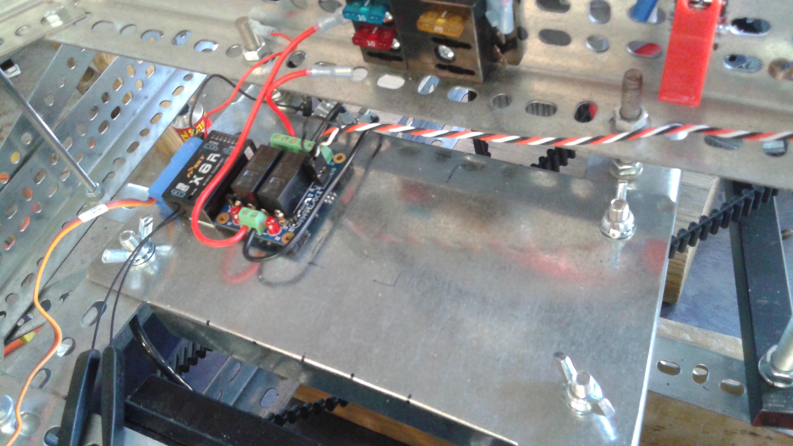
The other items I've been working on getting ready for the next test are the relays. I've added an electronics tray made of of thin galvanized steel and mounted using wing nuts. They are some neoprene washers to help dampen out vibration. I've started mounting some of the electronics using double sided tape, but I need to do some rearrangement. So far the receiver, relay board and BEC are mounted. The Pixhawk will mount on the center, below the fuse box.
![]()
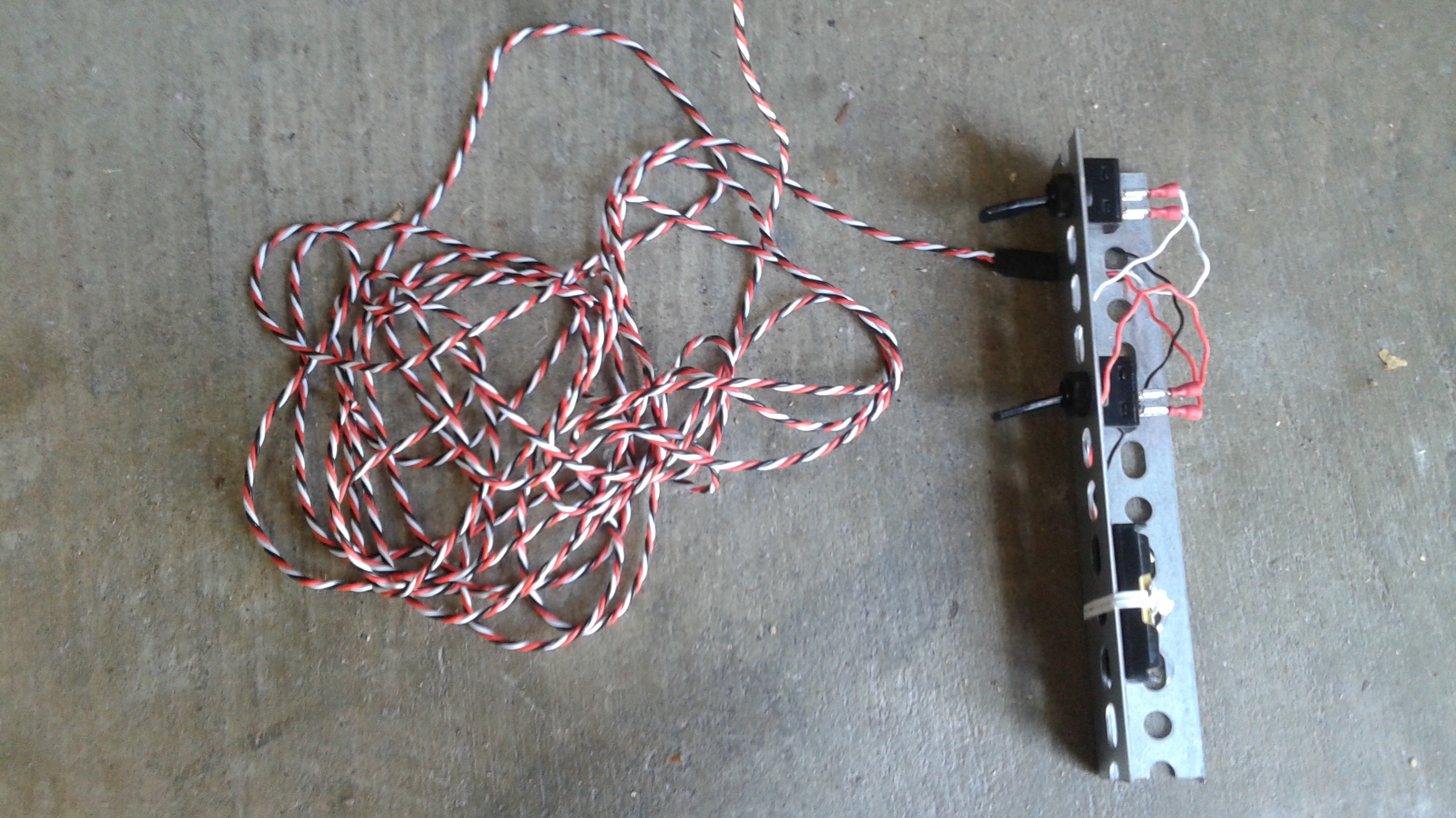
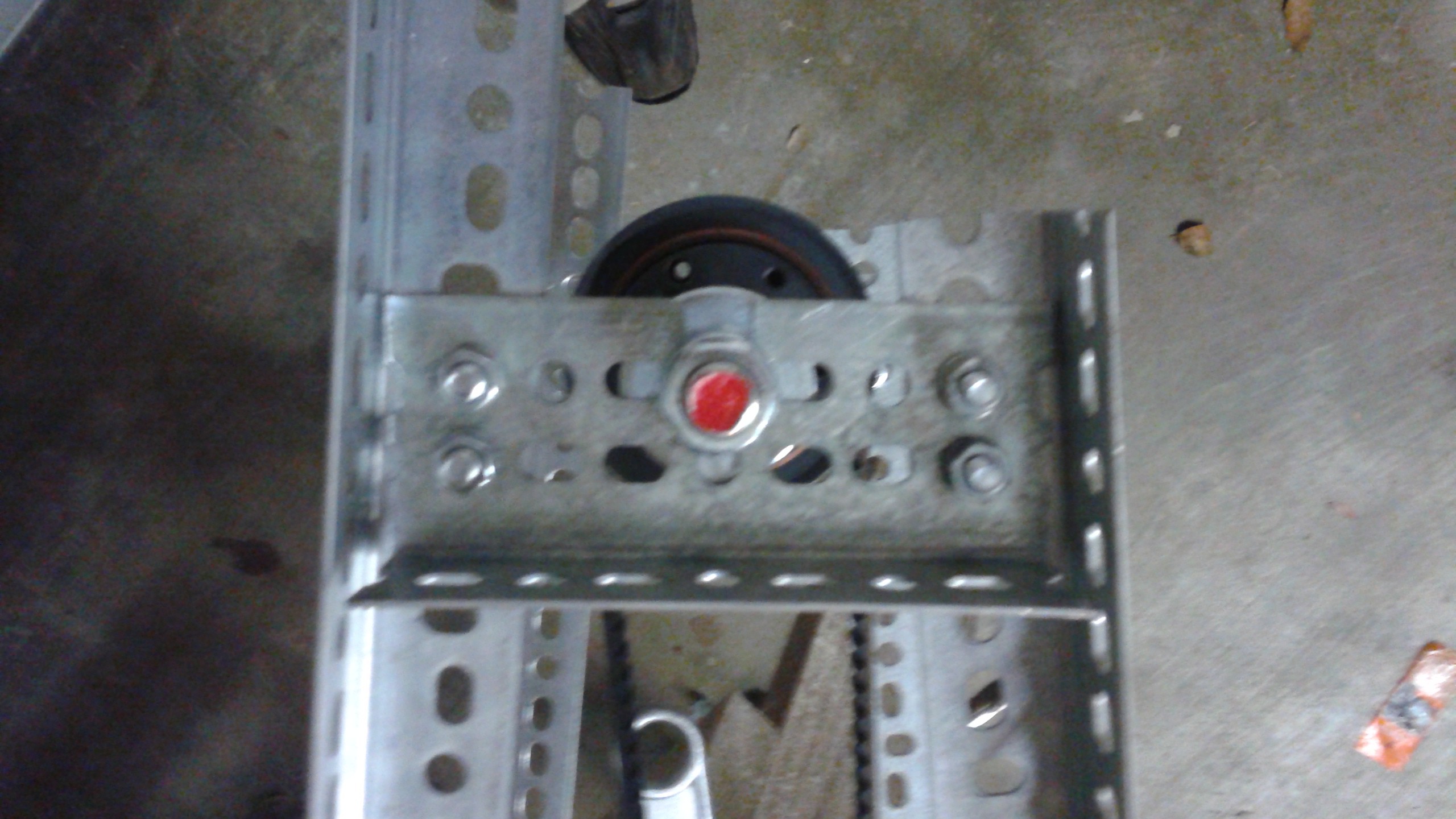
Since I don't have the software yet for the Pixhawk, and the relays can't be control directly through the RC receiver directly, I've created a wired remote for the relays. The remote has an on/off switch for the ignition and a momentary switch for the starter relay. The remote has 3 AAA batteries to supply 4.5V to the relays (they will take 3.3-5V ). I'd ordered 25 ft rolls of servo wire to make custom harnesses so I used on of these rolls to carry the signals until the controller is ready.
![]()
Once I get all these items finished up and the vehicle is back together, it'll be back to testing.
-
Houston Mini Maker Faire tomorrow (10/1)
10/31/2014 at 17:45 • 0 commentsI've been spending my time getting ready for the Houston Mini Maker Faire, tomorrow at Stafford Centre from 10 am to 5 pm. Goliath will be there and we'll also have the CNC router we used to make some of our parts. Be sure to stop by and say hi! More details can be found at http://www.houstonmakerfaire.com/
![]()
-
Conclusions from Round 2 of Testing and Next Steps
10/19/2014 at 15:37 • 0 commentsSo Round 2 didn't conclude with a hover test, but a lot of progress has been made. The engine has been run now for a total of 3 1/2 minutes, allowing some of the design flaws to be identified and worked out (improved battery mounts and improved tensioners). The downside is that the belt system still has an oscillation occurring, but it is very much improved. For completeness, I've uploaded video of Tests #7 and #8 (see below)
So one of the culprits is the tensioner pulley on the double sided belt. It should have been a 20 mm wide pulley, but when I did the tensioner redesign, the pulleys were on back order until mid-December, so I used the 50 mm wide pulley I had leftover from the previous design. The lack of a flange on both sides could be allowing the belt to move around, causing the oscillations.
![]()
There was another lingering issue and is the pulleys I used for the idlers on the single sided belt. Again I used parts I had on hand and using toothed pulleys on the flat side of the belt isn't ideal. To remedy both pulley situations I've ordered some flat belt pulleys for the idlers and then I'll move one of the toothed pulleys to the double sided belt. If that doesn't resolve the the oscillations, the next step would be to add some belt guides to the double sided belt.
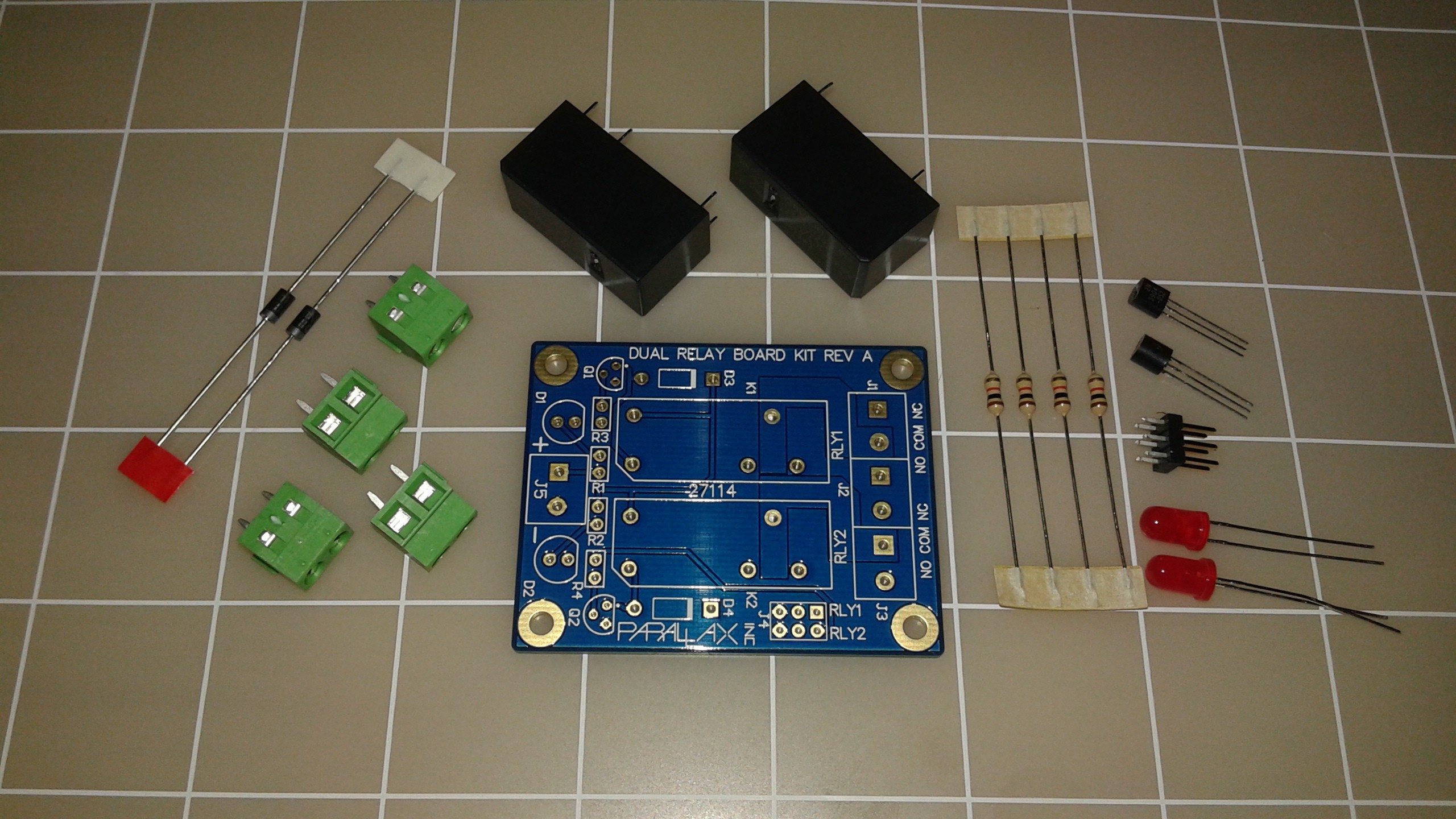
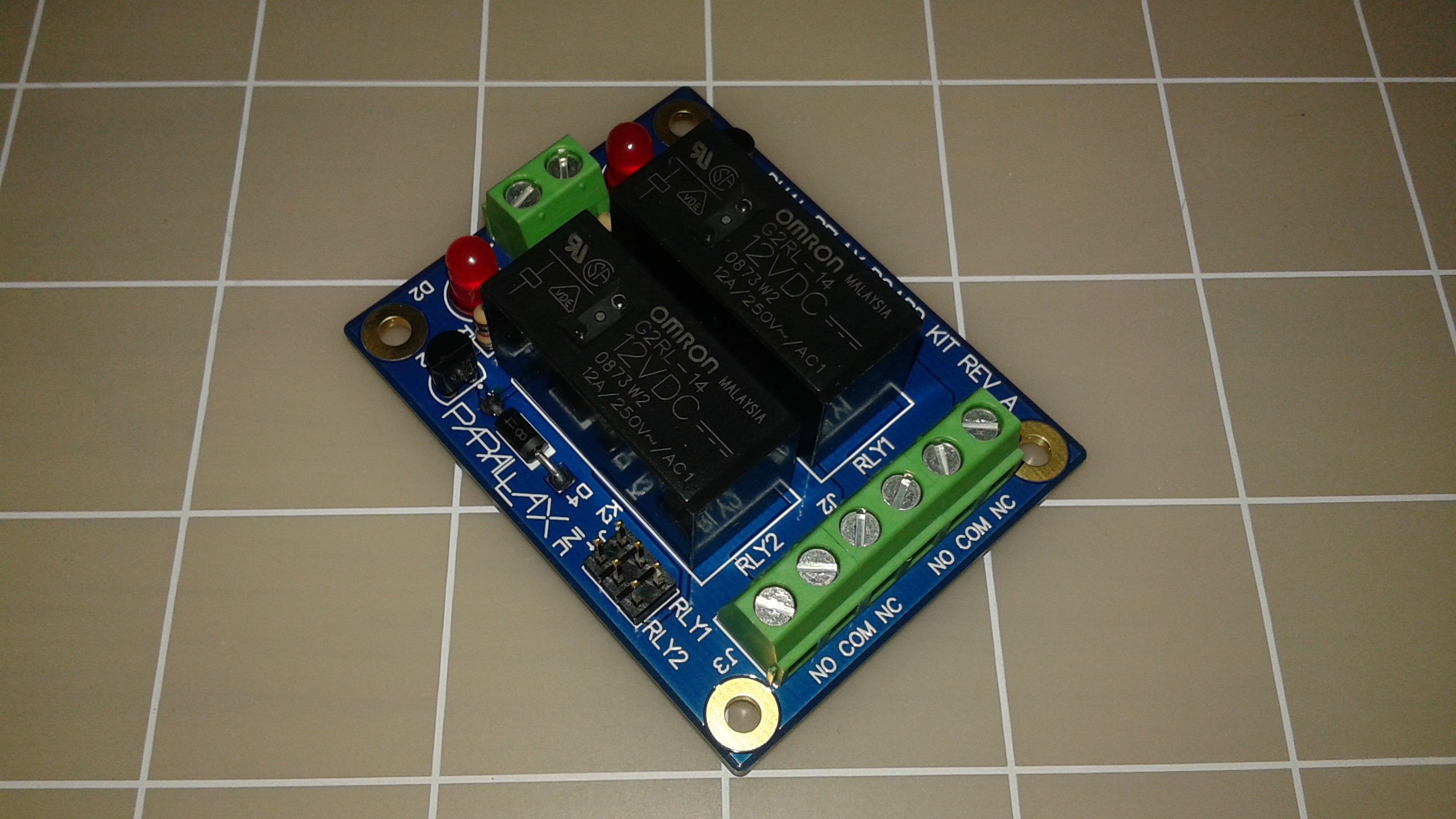
While I'm waiting for the pulleys to arrive, I'll be taking the time to incorporate the starter and ignition relays. I've decided on a dual relay board from parralax which arrived last week. I decided to omit adding a relay for the fuel solenoid, because it didn't seem like having separate control for the fuel shutoff was essential. My initial thought was the aircraft have a fuel shutoff in case of an engine fire, so Goliath should have a fuel shutoff. However, the fuel for Goliath isn't gravity fed, and If the engine is killed with the ignition, the fuel pump stops and the fuel will be cut off anyways.
The kit is pretty straight forward and it didn't take long to solder all the components together.
![]()
![]()
Once the other parts come in and the relays are incorporated, I'll repeat the same test configuration with the dummy props. Once the belts are solid then I'll add the real propellers on and do the run up.
One last thought was about weight growth. At work I deal with a lot of projects that are always weight challenged. In initially scoping out Goliath, I made conservative weight estimates to avoid all the redesign work that goes into trimming weight. However, I've added a lot of items that I hadn't initially planned for, so I weighed Goliath in it's current state. I did this by using a handheld luggage scale at the end of each of the arms and lifting up until each side was off the supports. The total weight right now is 160 lbs, 80 lbs less than the gross weight I was targeting. Ducting, controls and a tank of gas should be much less than this so for now it looks like things could come in underweight.
-
Testing - Round 2
10/07/2014 at 12:24 • 1 comment10/15 UPDATE: Good 3rd Gas Engine test! See bottom for details...
Ok, so things are finally in a good state to start doing the second round of testing. As I did before, I'll be updating this project log as I go, instead of making multiple logs. I'm trying to be cautious so that I don't have a repeat of breaking propellers so I'm breaking down the testing into smaller increments to make sure everything is good for the final hover test. I've already done two tests previously, so the next tests will be:
- Test 3 - Single Sided Belt only with Dummy Props, Starter Only COMPLETED 10/6
- Test 4 - Single Sided Belts only with Dummy Props and Belt Guards, Starter Only COMPLETED 10/8
- Test 5 - Single Sided Belts only with Dummy Props and Belt Guards, Gas Engine COMPLETED 10/11
- Test 6 - Both Belts with Dummy Props and Belt Guards, Gas Engine COMPLETED 10/13
- Test 7 - Repeat of Test 6, attempting to address the belt oscillation COMPLETED 10/13
- Test 8 - Repeat of Test 6, attempting to address the belt oscillation
- Test 9 - Hover Testing
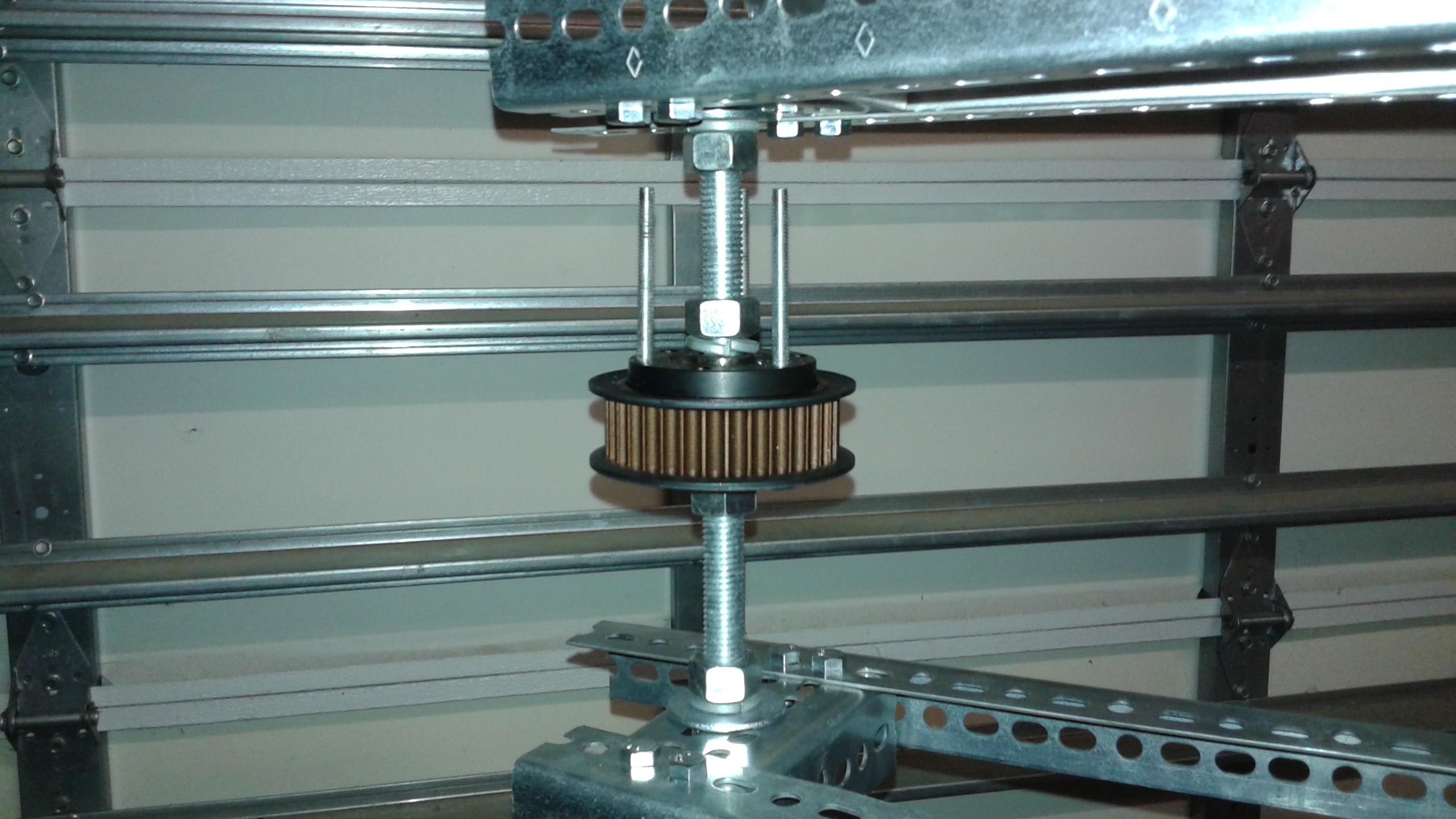
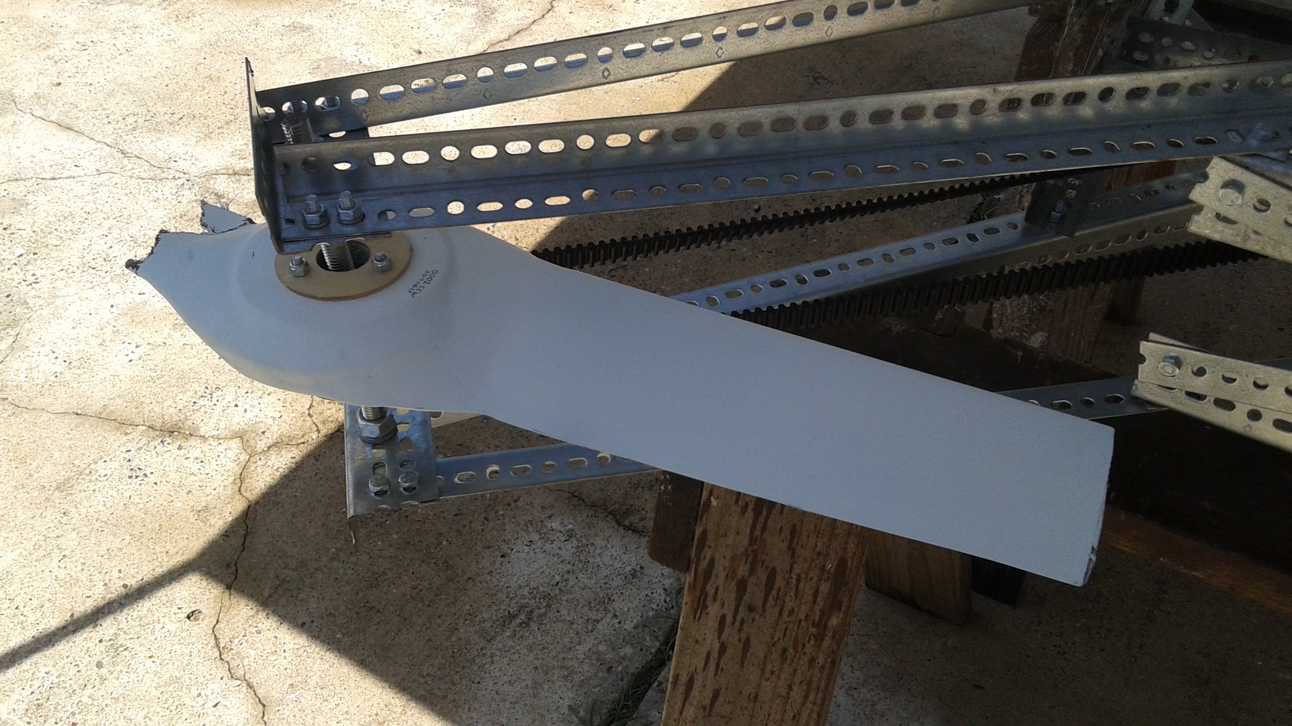
So it took a while to get here because of the redesign of the belt tensioners, redoing the prop mounts and supports, etc. Last week I was in the process of making the final adjustments and alignments when I realized there was going to be an issue with the vehicle due to some of the changes I had made. One change I forgot to document was that I had flipped the propeller pulleys over. This is important because of the bushing attached to the pulley. By flipping the pulley over, it added a half inch of additional clearance between the propeller and the belts.
![]()
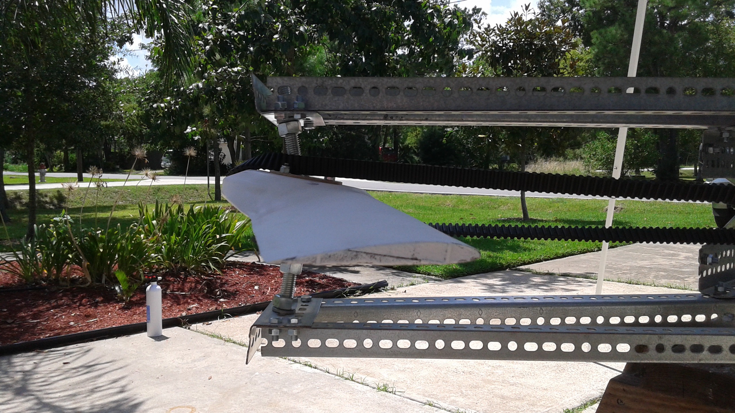
What I didn't take into account is that this reduces the clearances above the prop. The prop would fit, but the prop tips will deflect upwards and I didn't want to risk destroying another propeller. There was lots of clearance beneath the pulley, but it was as low as it could go do to the center beams and engine shaft length. You can see this a little in the next photo.
![]()
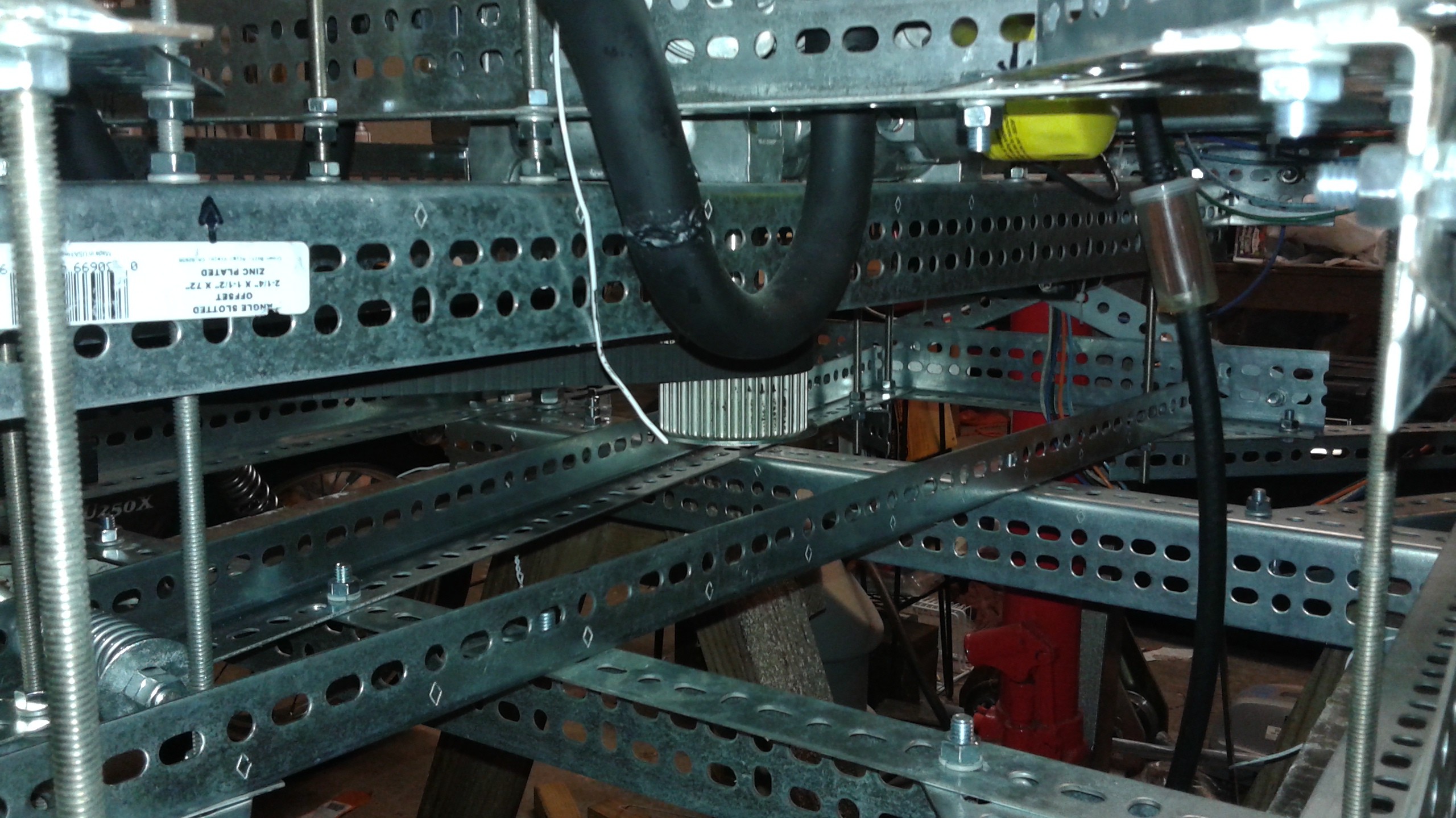
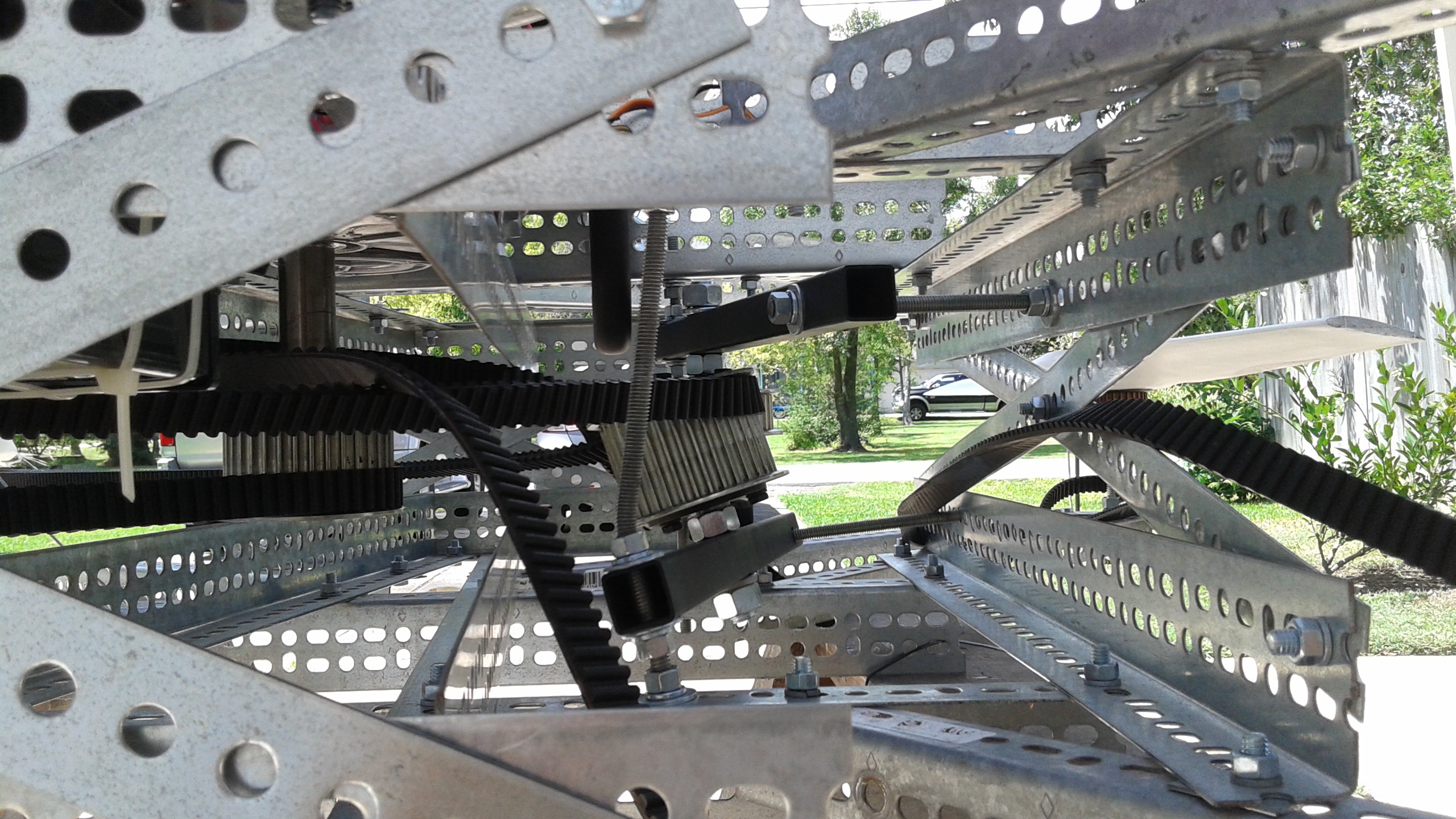
The solution I came up consisted of several parts. The first part was to replace the lower center beams which stood 2 3/4" tall with 1 1/2" tall beams. These aren't carrying the load of the engine like the ones above, I had just chosen to match these beams to the ones above them. This gave an additional 1 1/4" to move the belts downwards, but the pulley was already as low as it could go on the shaft. The next part was to lower the upper center beams with the engine attached. This was done by replacing the bolts one at a time with all-thread and then turning the nuts to slowly lower the assembly. The all threads and nuts act as stand offs. The engine was lowered 1" and the final result is shown below
![]()
This modification also gets the cg lower which will hopefully make control that much easier.
Test 3 - Single Sided Belt only with Dummy Props, Starter Only
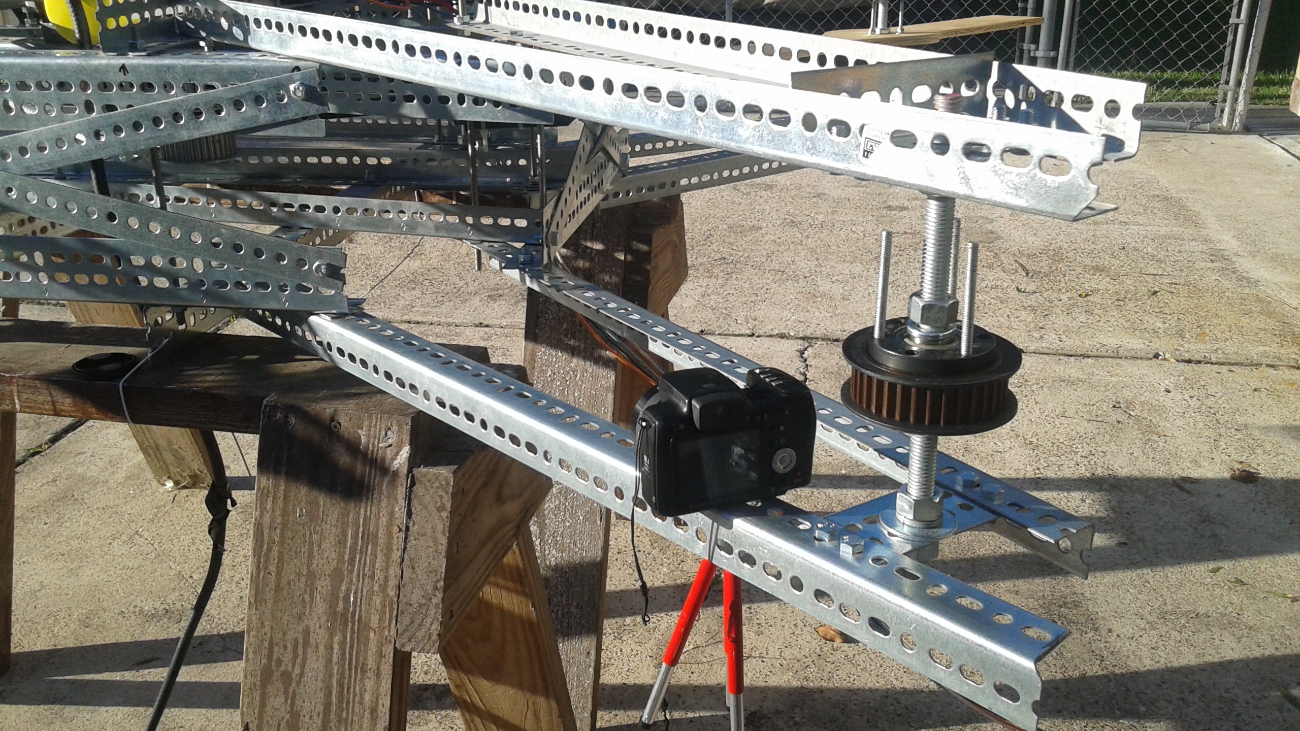
This test was done on 10/6 and it went well. To get a better view of the belts, a second camera was used, attached to the frame. The belt didn't appear to oscillate.
Below is where the second camera was mounted. I simply put the camera on the frame and screwed the mini tripod onto it through one of the slots.
![]()
It shouldn't take too long to complete the belt guards and run the next test.
Test 4 - Single Sided Belts only with Dummy Props and Belt Guards, Starter Only
The last of the upgrades to address the issues from the previous round of testing are the belt guards. These are intended to keep the belt from being able to interfere with the propeller. They were constructed from a five inch wide strip of 24 gauge galvanized steel bent to shape. Last night (10/7) I completed making the first 2 and bolted them to the frame.
![]()
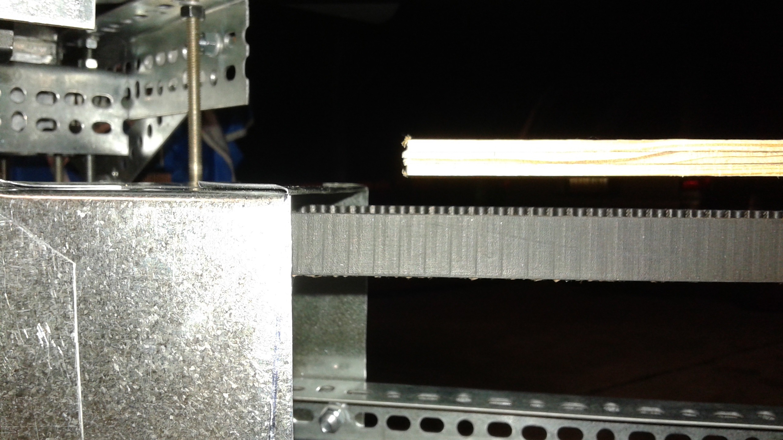
On the upper surface, 1 one inch wide strip was folded over so that if the belt does hit the belt guard, there isn't a sharp edge that could cut the belt. The picture below shows the clearances. I had originally intended to have the belt guard in between the propeller and the belt around the tip, but with the lack of clearance, it seemed having it just beyond the propeller was more practical.
![]()
Things are all set for the next test. When I get home tonight I'll set up the test and make sure these are going to work okay.
10/8 8:30 UPDATE
So the test went well. Even with the tight clearance shown there was no signs of the belt impacting. I moved the second camera to beneath one of the active rotors to get a view of the belt guards. It's a bit shaky, but looks cool.
Next steps are getting the throttle servo connected and the new gas tank attached and I'll run the gas motor with belt hardware as is.
Test 5 - Single Sided Belts only with Dummy Props and Belt Guards, Gas Engine
10/10 9:30 PM UPDATE
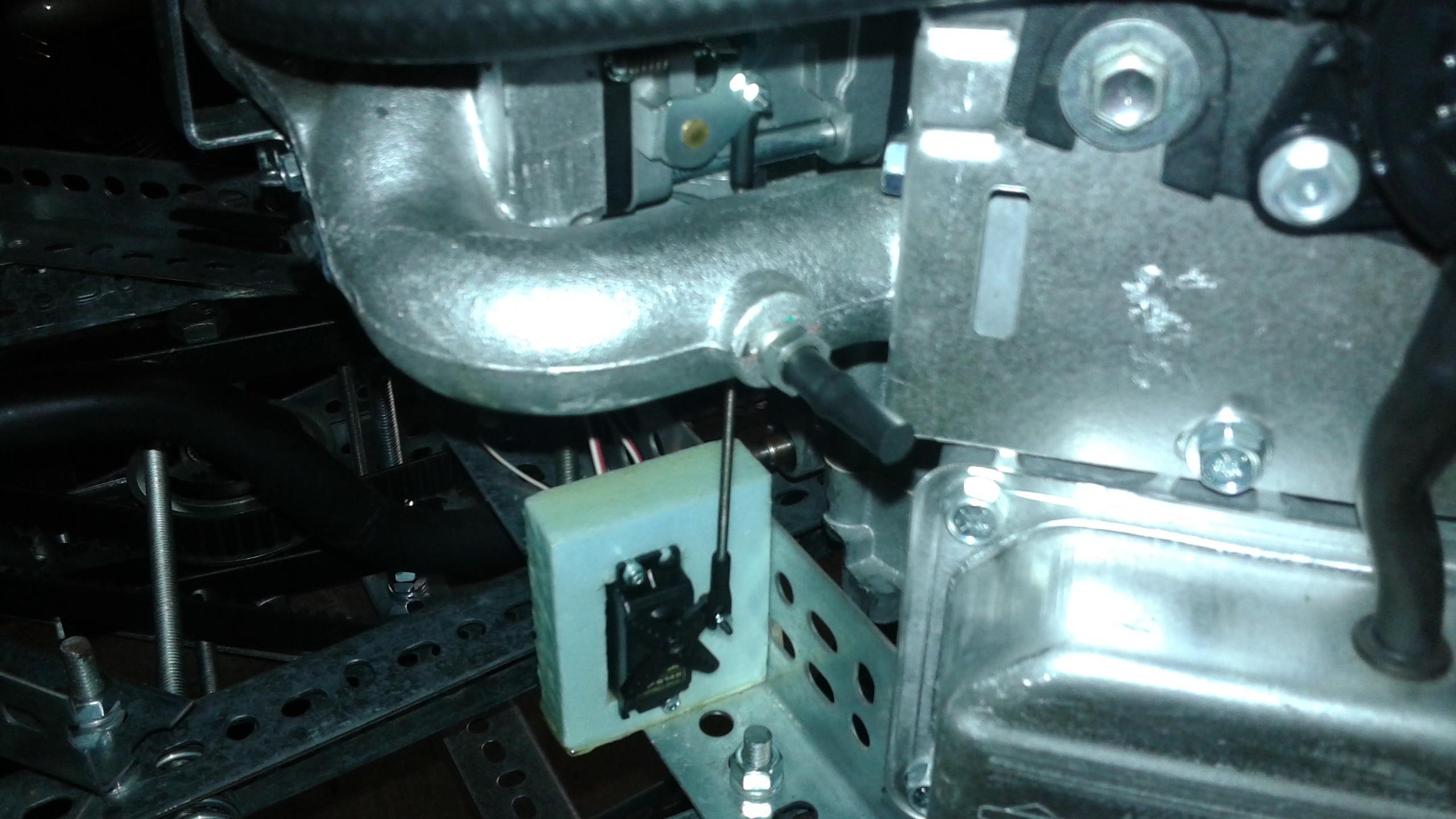
The throttle linkage is now hooked up. It took a couple of iterations to get it right. The linkage is made from 4-40 all-thread rod with Ball and Socket Rod ends. The servo is a standard RC servo and the servo mount is made from a foam block coated with epoxy to stiffen it up.
![]()
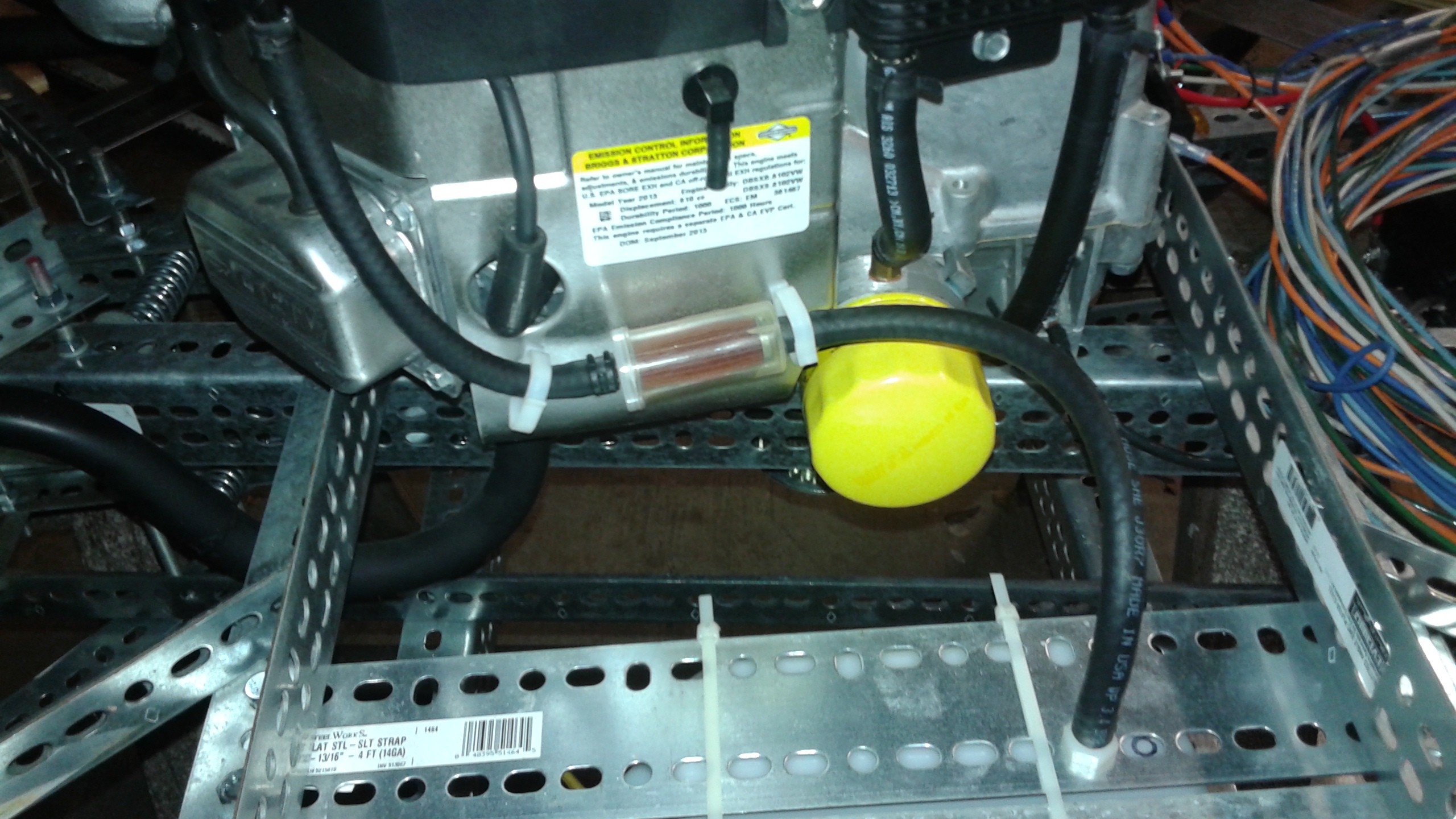
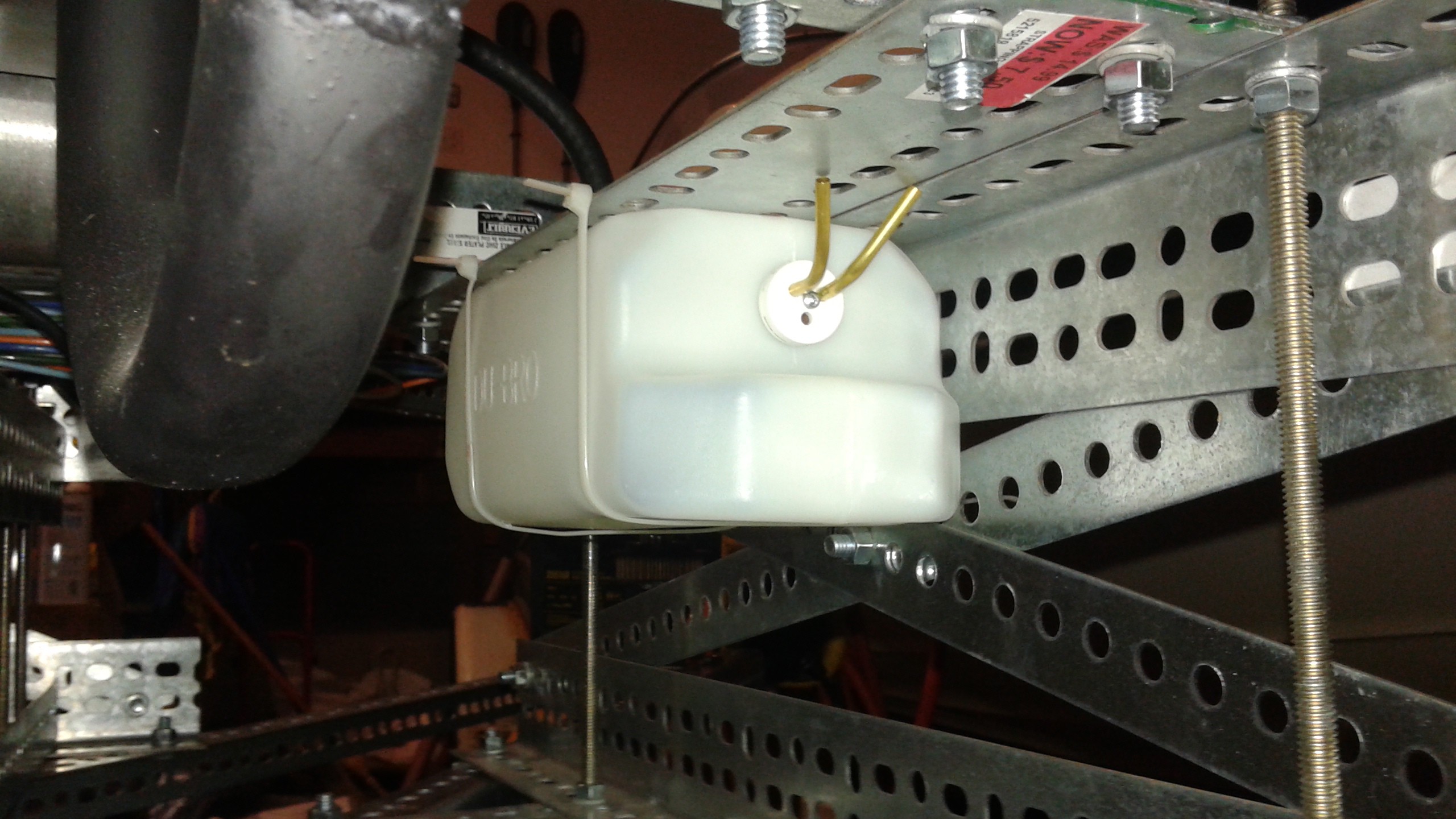
The fuel tank is a 50 oz (1500 cc) tank for large RC planes. I've mounted it inside the frame, on the opposite side from the pulleys.
![]()
![]()
All that's left to do the next gas engine test is to straighten up some wires and fill the gas tank. So I plan to conduct the test tomorrow (10/11).
10/11 2:15 PM UPDATE
Today's test was successful! After having some initial difficulty getting the engine started, it came to life. The problem seemed to be that it needed the choke to get started up. There's no servo on the choke, so if it continues to need the choke to get started, then I'll need to think about adding a servo.
The test started at about half throttle and after a few seconds, brought it down to 25% throttle. It was run for a good 20 seconds and the belts and the dummy props seemed to hold steady. A visual inspection afterwards didn't turned up anything of note. The audio really doesn't do it justice, it's loud and intimidating. (For those safety conscious people, we are ducked down below a chain link fence during the test).
With this test out of the way, the next step is to hook the second belt back up and make sure the system as a whole behaves before added on the real propellers.
Test 6 - Both Belts with Dummy Props and Belt Guards, Gas Engine
10/13 3:30 PM UPDATE
Well if you haven't seen today's announcement for The Hackaday Prize, [spoiler alert] Goliath wasn't selected. The judges have picked some great projects and the best of luck to the remaining contenders.
Meanwhile, progress with Goliath is continued today with Test #6. This was the first test with both of the belts connected. During the test the gas engine was run for about 30 seconds. Nothing seemed amiss during the test, but reviewing the footage it seems that the double sided belt is still moving around quite a bit. It's also interesting to see some of the harmonics present, particularly with the engine, moving about a bit.
I'm probably going to adjust the belt tensioners and repeat this test to see if the belt oscillations can be further reduced. There are thunderstorms going around today and I was lucky to get this test in before it started raining, so we'll see when I'm able to run the next test. I'm also starting to set up the test rig for the hover test.
10/13 10:00 PM UPDATE
I did get to test a second time today, repeating the conditions for Test #6. I had tightened up the belt tensioner for the double sided belt to try to reduce the oscillations. There wasn't much improvement, but I think I may have found the culprit. The prop pulleys were a bit higher than the main drive pulley so that they weren't alinged as well as they should be. I think the oscillations could be triggered by the belt riding up the pulley, and then bouncing against the other belt.
The total test time was one minute. With the longer testing, the paint on the exhaust is starting to off-gas a bit. The other thing that was apparent was that the battery mount is inadequate. It's currently slung underneath a wide piece of plate metal and it was bouncing up and down visibly from where I was viewing the test, (but not seen well from the 2 other cameras). I'll need to add a support underneath it so that It's mounted more securely. I was lucky I stopped the test when I did because a bolt was rubbing against the battery box and could have worn through it.
The prop pulleys have already been adjusted so once the battery mount is fixed, it'll be time to test some more. Even if the belt problems are fixed, it may be wise to increase the test times to make sure all the bugs are worked out before adding the propellers.
10/15 1:00 PM UPDATE
This morning I did another repeat of the Test 6 conditions. New battery plate held together nicely and the test was for 1 1/2 minutes, bringing the total run time on the engine up to 3 1/2 minutes. Everything held together, but the one belt still seems to be bouncing around. I could probably move forward with some risk, but I'd like to get the belt system rock solid before I move on to the hover testing. I've got some additional ideas, but it'll mean getting some additional parts and standing down from testing for a week or so. I'll talk about them and a Round 2 testing conclusions in my next project log.
-
Houston Mini Maker Faire 11/1
10/06/2014 at 12:07 • 0 commentsFor those in the Houston area on 11/1, Goliath will be displayed at the Houston Mini Maker Faire! Even if the vehicle is flying by then I won't be running the gas engine for safety reasons, but be sure to come by and check it out in person! Get more info and register at:
http://www.houstonmakerfaire.com/
![]()
-
CAD
10/04/2014 at 01:10 • 0 commentsDuring some downtime I've been able to work further on the documentation and lately some of the CAD. I've been using Cubify Design to generate the CAD. I had tried out FreeCAD for a while, but it's still early in development. While Cubify isn't open source, it's a good balance between cost and capability.
The github repository has the CAD that I've finished so far, mostly the frame pieces. If you have Cubify check out what's up there. Right now there is only one STEP file of the frame assembly, but more STEP files will be added as it's completed.
Frame Assembled
![]()
Frame Exploded View
![]()
-
Tensioner Complete
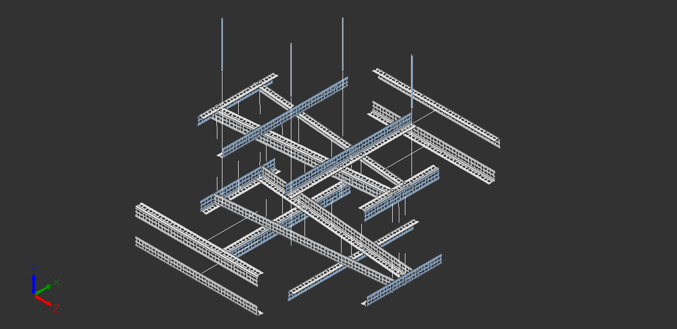
09/27/2014 at 18:50 • 0 commentsIt took a bit more effort than I envisioned to rework the belts. One of the downsides to HTD belts is that they only come in specific lengths. You can splice them, but the tensile strength is reduced by a minimum of 60%. So when I adjusted the layout, the propeller hubs needed to be extended a slight bit to take up the extra length and I didn't leave any extra room on the ends, so I needed to cut new supports. This wasn't too bad because I wanted to rework the propeller supports to flip the shaft mounts around and I did get to reuse half of the prop supports since some are different lengths. I also left some extra on the ends in case it's needed later. I think overall it'll help the design be more stable and allow for slightly larger propellers if they are needed. The new belt layout is shown below.
![]()
The propeller supports have been flipped around and instead of a hole, there is now a slot to allow the entire propeller assembly to slide in and out easily. This will make working with the vehicle much easier since the entire assembly had to be taken apart to take the propellers on or off.
![]()
The new tensioners are a big improvement, but took a lot of minor adjustments to really get the design perfected. Previously the pulley was only supported on one side. A longer bolt was swapped out and the pulley is now supported on both sides. Two spring loaded arms are now used to provide tension to the belt. Below is a video showing the tensioner for the single belt. The double sided belt tensioner will now be built using this design.
I'm targeting to do another test during the first week of October. I still have the belt guards to install, but the more difficult portions of the redesign are complete. Design of the ducts and the rest of the hardware has started so things should hopefully go quickly once the test is complete. I've also uploaded a new Semi-Finalist video in anticipation of Sunday's deadline.
-
RC Electronics are here!
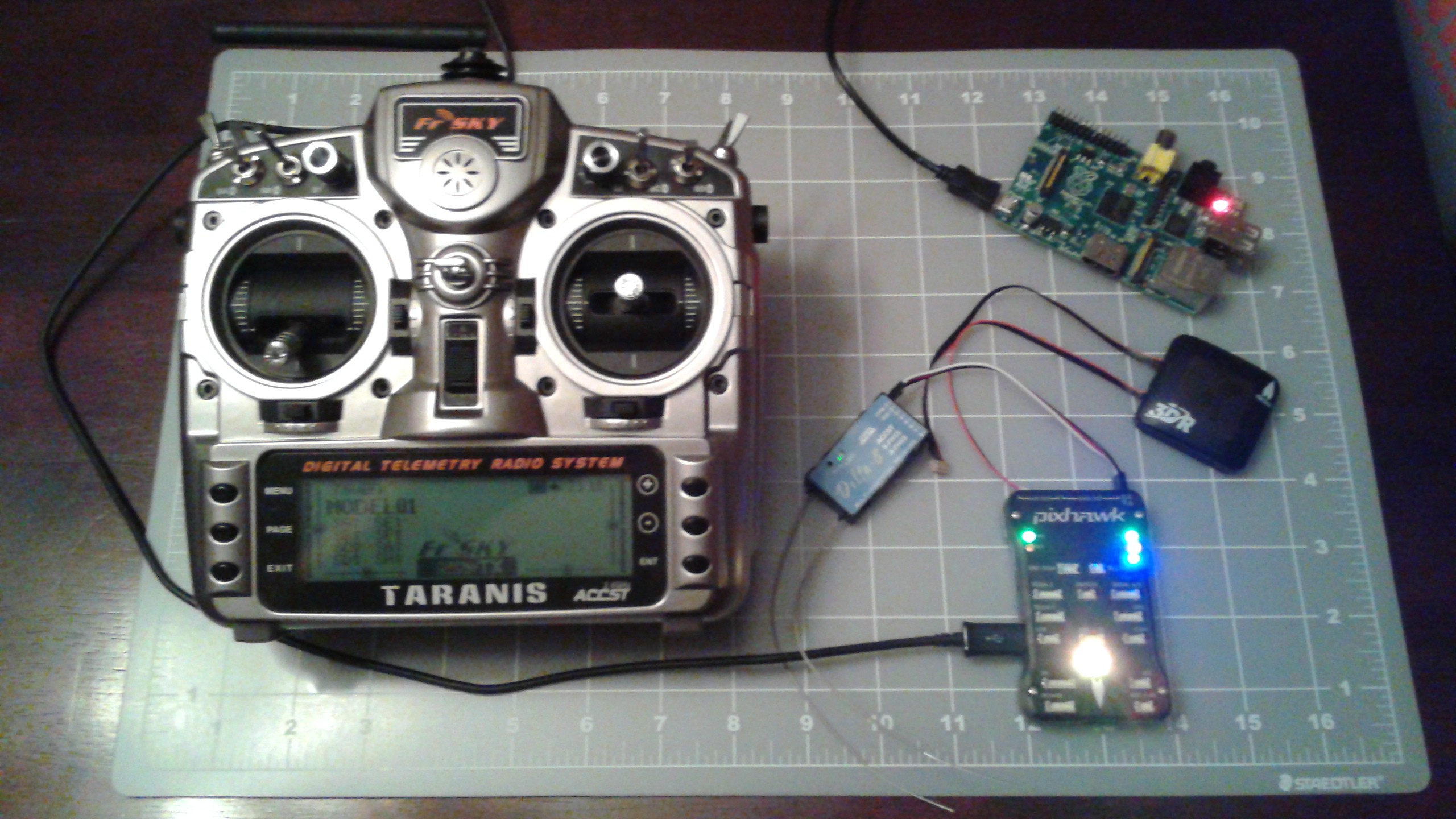
09/20/2014 at 02:57 • 5 commentsThis last week I received the rest of the major electronics needed to complete the project. Shown below is the FrSky Taranis Trasnmitter, FrSky Delta 8 Reciever, Pixhawk Flight Controller, GPS Module and a Raspberry Pi.
![]()
There is a good overview on Pixhawk compatible RC Receivers already on the ardupilot wiki. In summary the pixhawk can save space by using a single PPM input instead of 8 PWM inputs. Any RC Receiver with PWM output could be used, but an encoder would have to be used. The wiki page highly recommended the FrSky Delta 8 since it can output the PPM signal. The Delta 8 is designed to connect to a number of receivers. The FrSky Taranis transmitter was also compatible with the Delta 8 and recommended again by the ardupilot wiki. It'd be nice to have the OSRC, I hope that it's able to get funding to finish development.
Now that I've got these items in hand I can start on getting the Pixhawk and Raspberry Pi to talk to each other using Mavlink. Luckily this has been documented on the ardupilot wiki as well. Also thanks to my friend Drew for offering his unused Raspberry Pi for the project!
-
Redesign Progress
09/14/2014 at 16:57 • 8 commentsI've been working on making changes to Goliath. As I discussed previously I had suspected the need for a one-way bearing to prevent slack from occurring during a shut down.
Helicopters use one-way clutches to allow for auto-rotation after an engine failure and one-way bearings are common in RC applications for cars and helicopters. The problem is that I haven't found a one-way clutch or bearing that will work well with Goliath. The simplest solution would be to swap out the QD Bushing on the main pulley with an idler QD bushing where the bearing is replaced with a one-way bearing.
The drive shaft for the gas engine has a 1 1/8" diameter shaft with a keyway. After doing a lot of research, it appears that one-way bearings only come in Imperial sizes up to 1". They are made in metric sizes, in 5 mm increments. There are one-way clutches that could be attached the drive shaft, but they start at $650 and they're aren't any HTD pulleys that will attach directly to the clutches.
There are electric clutches that are made for these size engines that would work, the problem would be then determining when the engine is shutting down and disengaging the clutch. Could be an option.
However after taking a look at the video again and the belt diagram, the portion of the belt that developed slack, would have been in tension during shutdown. This likely means that the belt failure just happened to occur around the time I shut down and that the cause was failure to maintain tension during normal operation.
Smerfi, pointed me to a document that addresses belt tension. I'd read it before when researching HTD belts about a year ago, but had forgotten some of the information. One of the important parts is that the belts stretch during initial use. This could have been the initial issue.
With that in mind, I've been working on making some changes to Goliath. The first is to change the belt tensioners. The two belts both attach to one of the tensioners, due to the nature of the belts, this means that if one gets tighter the other gets looser. I'm changing it so that they don't share any pulleys other than the main drive pulley. I'll also add springs to the tensioners to automatically adjust the tension.
I'm also stiffening up the structure vertically. I've replace some of the bolts with all-thread rods that go from top to bottom. This will eliminate some of the flexing that occurred during the testing.
![]()
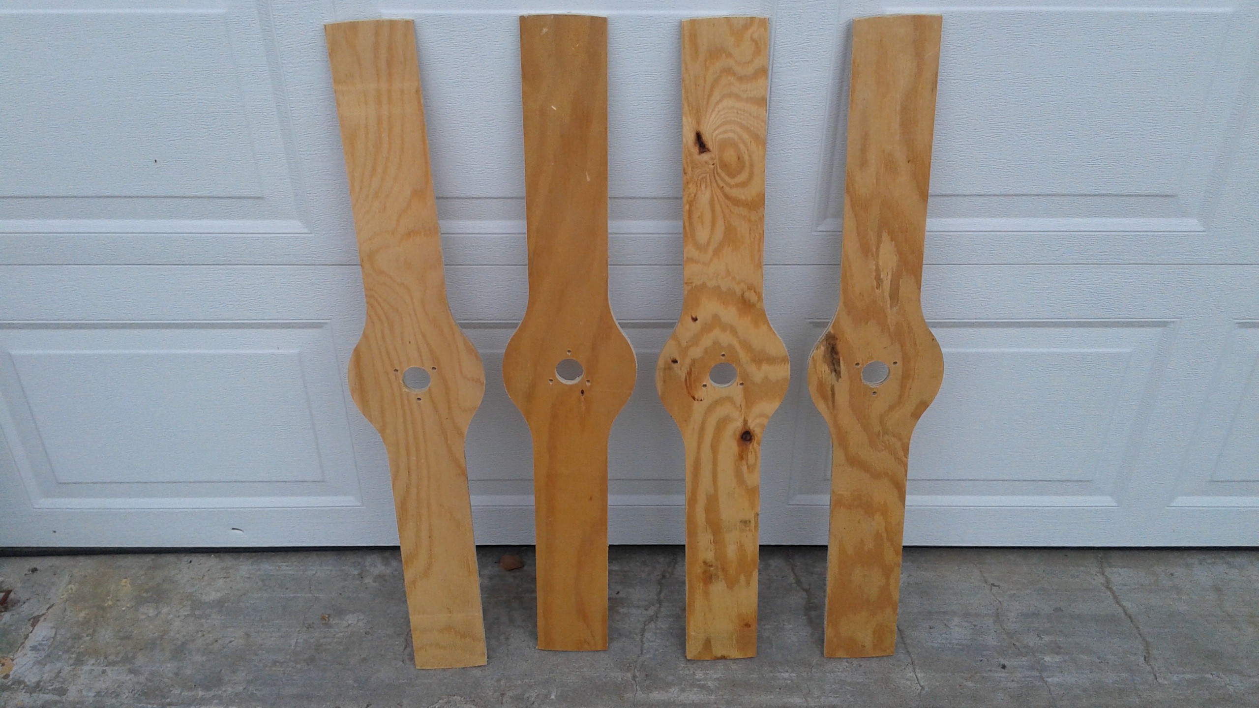
When the changes are completed, the first test will be with some test propellers. This was a suggestion by a coworker. They are simply 1/2" plywood cutouts that will give the engine some load and can easily be replaced. Once the belt system has been tested up to speed then I'll switch back to the propellers.
![]()
Meanwhile, the replacement propellers are both cured and I'm back to the tedious process of sanding them. I've also been updated the description section for Goliath including an overview diagram and some more details on the electrical system. Things have slowed down a bit though since I had to go out of town for work and now I've gotten sick. But once the belt system changes have been made things should hopefully progress smoothly from there.
-
Picking up the Pieces
09/02/2014 at 12:11 • 5 commentsIf you hadn't seen the previous post yet, the gas engine was started for the first time, but during the process the vehicle was damaged.
Afterwards, I took an assessment of the damage to Goliath and tried to figure out where things went wrong.
![]()
![]()
![]()
After watching the video a few times and looking at the damage to the vehicle, I think I have a good idea of what went wrong and what I can do to prevent it from happening. Things were running good until the engine was shutoff. At this point one of the belt started losing tension. You can see this in the video at the lower right hand belt starts to flap. This was likely do the the engine spinning down faster than the belt. At some point the belt gets so much slack, that the belt bounced up and the propeller went under it and the belt got wrapped around the prop. Once it was tangled the belt cinched up really tight and bent two of the propeller shafts and the belt tensioner support. The other propeller attached to the belt was sheared off when it's axle was bent and the propeller hit the angle iron support.
The changes I need to make to the vehicle to keep this from occurring again are:
- Add a one-way (overrunning) clutch to the engine pulley
- Add belt guards to prevent the belt from flying up into the path of the propellers
I may also need to add some auto tensioners, I need to do a bit more research into it.
Otherwise the test went well. We could really feel the wind coming off the vehicle. I'm really amazed that the belts are as strong as they are. I would have thought that the belt would have snapped in this situation. I've already started on making two new propellers and hopefully the process will go faster now that I've done it a few times.