Peter McCloud
-
Propeller Issues
07/02/2014 at 00:39 • 0 commentsThe last few weeks have involved a lot of work, but not very much progress. Previously I had shown the latest propeller shape cut out on the router and I cut two initial rotors. Most of the supports were removed (with exception to the tips) and the foam was lightly sanded to remove the tool marks. Last Wednesday I received the fiberglass fabric and last weekend I started the layup process.
![]() It didn't take very long to have my first lesson learned. I'm using West System epoxy and I had gone out and purchased slow hardener (206) knowing that it was too hot (Houston during the summer) for the fast hardener (205). I really underestimated the working time I would have with this and it was gelling before I even got halfway through the first layer of fabric.
It didn't take very long to have my first lesson learned. I'm using West System epoxy and I had gone out and purchased slow hardener (206) knowing that it was too hot (Houston during the summer) for the fast hardener (205). I really underestimated the working time I would have with this and it was gelling before I even got halfway through the first layer of fabric.I then went and got extra slow hardener (209) and started again with the second foam blank. That worked much better with the heat and I had enough work time to get all three layers of fiberglass over the entire blade. Shown below is the propeller with 2 layers.
![]()
The second lesson learned was the the foam is not stiff enough to support the weight of the uncured epoxy and fiberglass when working with it. As I would turn it back and forth to get the fiberglass on it the blade would flex and the previous fiberglass layers would slide and start air bubbles (I kept working the air pockets out, but the final product has a lot of air pockets in it). After getting all the layers on it, it was wrapped up and placed in a vacuum bag.
After getting the cured product out of the vacuum bag the next day ( I guess I forgot to take pictures at this point), the final product showed the previously mentioned air pockets and one of the blades was twisted strangely, ruining the propeller. So the third lesson was that the supports at the tips are insufficient for keeping the blade in place in the vacuum bag. I'll have to build some sort of support to hold it in place during the next attempt.
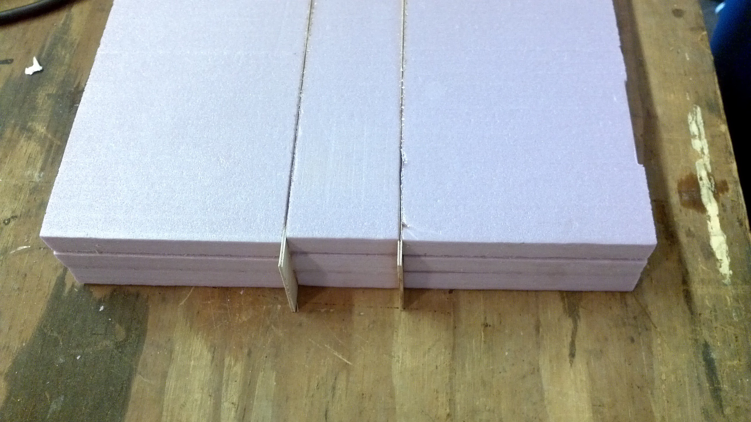
To fix the stiffness issue, I borrowed a technique from surfboard building, where they use wood strips along the center of the foam to add stiffness. The wood I choose was 1/16" thick birch plywood. I cut the 10" wide foam block into three pieces and used epoxy to glue the three sections and two wood inserts back together.
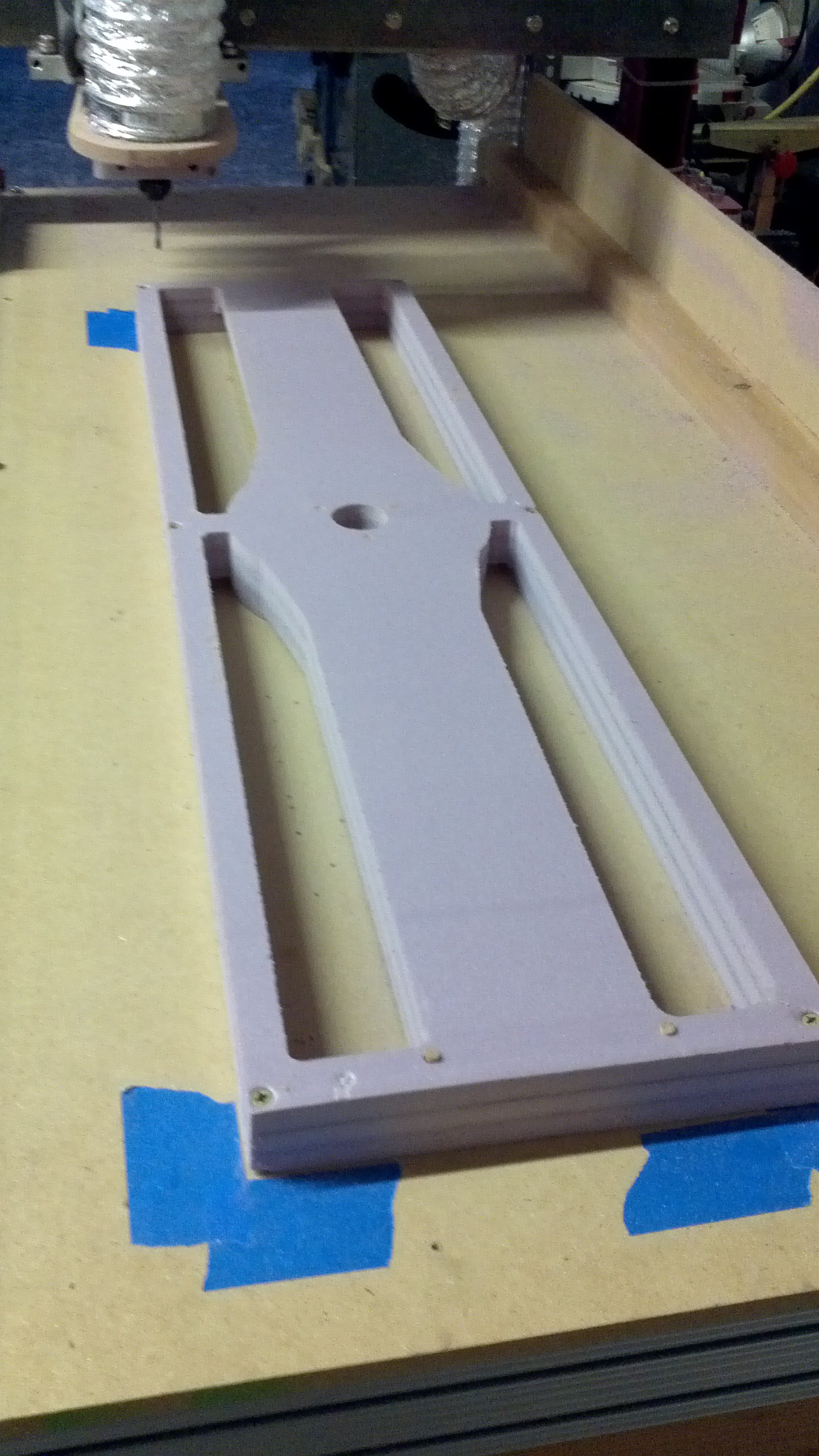
![]() After trimming off the excess, I started cutting a new propeller. The wood strips didn't seem to affect the routing and everything seemed to be going alright. Then for some reason I haven't figured out yet, halfway through the finish pass on the top side the CNC Router lost sync with the computer. Now I've had this happen on one or two occasions and I just restarted the g-code from the beginning and it'll be fine. This time I decided to restart the cut in the middle of the program, otherwise I didn't have enough time to let it finish before I went to work.
After trimming off the excess, I started cutting a new propeller. The wood strips didn't seem to affect the routing and everything seemed to be going alright. Then for some reason I haven't figured out yet, halfway through the finish pass on the top side the CNC Router lost sync with the computer. Now I've had this happen on one or two occasions and I just restarted the g-code from the beginning and it'll be fine. This time I decided to restart the cut in the middle of the program, otherwise I didn't have enough time to let it finish before I went to work.I really thought I had done everything right, but the results show that was not the case.
![]() It's lucky I'm working with foam because if this was anything harder, it would have messed up the machine.
It's lucky I'm working with foam because if this was anything harder, it would have messed up the machine.In the meantime I've ordered and received a PixHawk flight controller and I'll get started on learning that soon. I'm also getting the frame ready to do some load testing to make sure it's sufficiently strong enough before running the engine. I've got another propeller blank curing and now that I've got some confidence in the tool paths I've been using I'll start posting those to the github shortly.
-
Building the Exhaust System (April to May)
06/24/2014 at 12:25 • 1 commentWith the frame completed the next step was the exhaust system. Since Goliath is a unique vehicle, there wasn't any off the shelf products that would work, so a custom exhaust was needed. The engine's 30HP rating is with the air filter removed and no exhaust, so keeping the back pressure as low as possible was important. The engine has two exhaust ports so a dual exhaust system was built. The exhaust system was started from a exhaust kit and muffler intended for racing go-karts. The most difficult part to find was the right exhaust flange to fit the engine. After spending some time looking around, I decided to try making the exhaust flange out of steel on the CNC Router.
The CNC router used was a CNC Router Parts 2448. It's a very beefy router, but it's not made to be cutting steel, same as most CNC Routers. After doing a bit of research, it seemed that it would be safe enough to attempt cutting the two flanges I needed, as long as the machine went really slow so I don't put too much stress on the system and used a coated end mill to help keep the temperatures down.
It worked out ok. As you can see from the video, I didn't set the depth deep enough on the first pass. The biggest problem with the final piece was that the bar stock I used wasn't very flat, which meant that it wouldn't create a good seal. In the meantime I found a universal flange that would work with some extra welding and decided to go that route.
Below are the exhaust parts kit used to build one side of the exhaust.
![]()
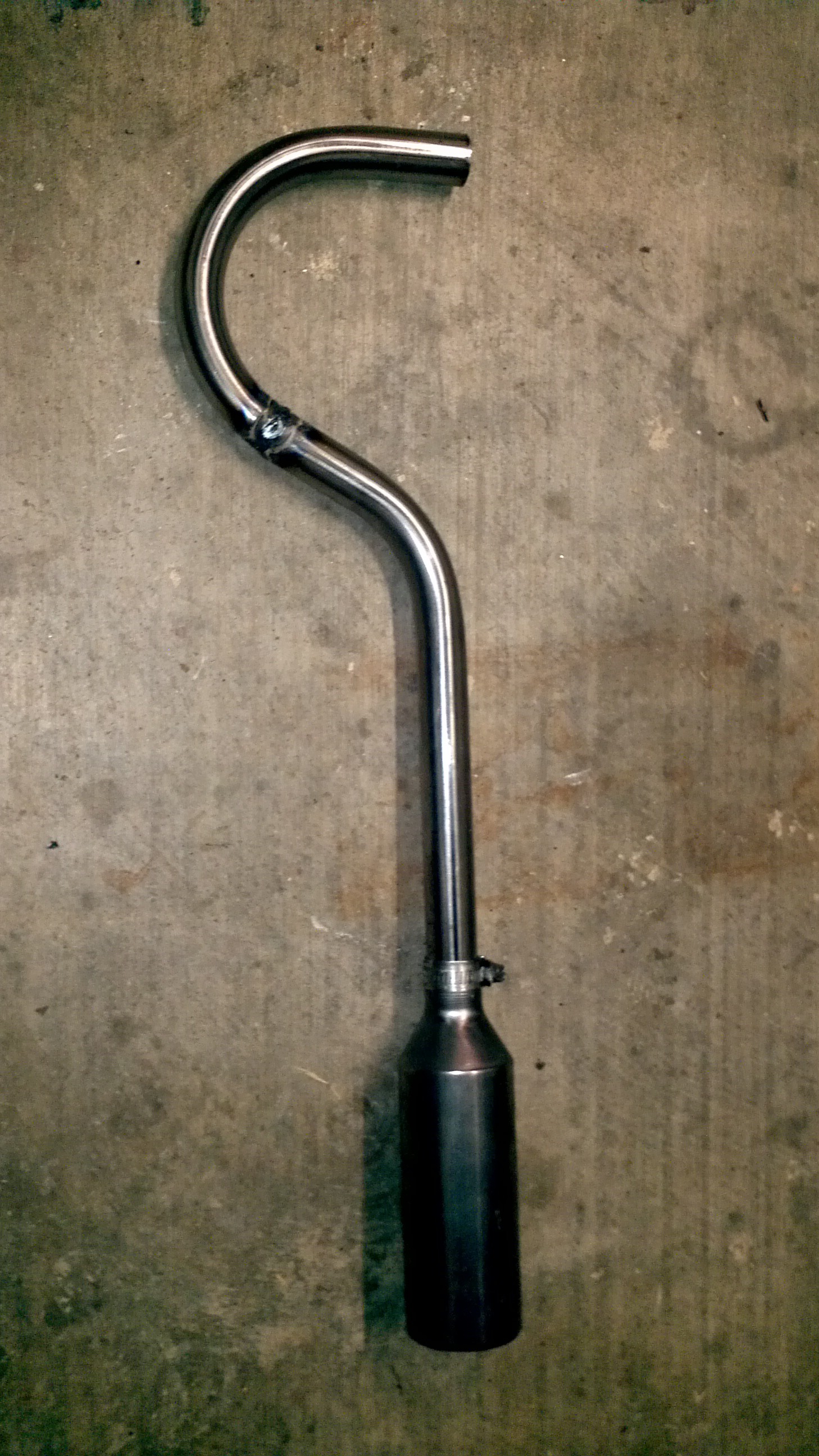
After test fitting the parts together on the vehicle, they were taken back off and welded together. Below are most of the elements welded together.
![]()
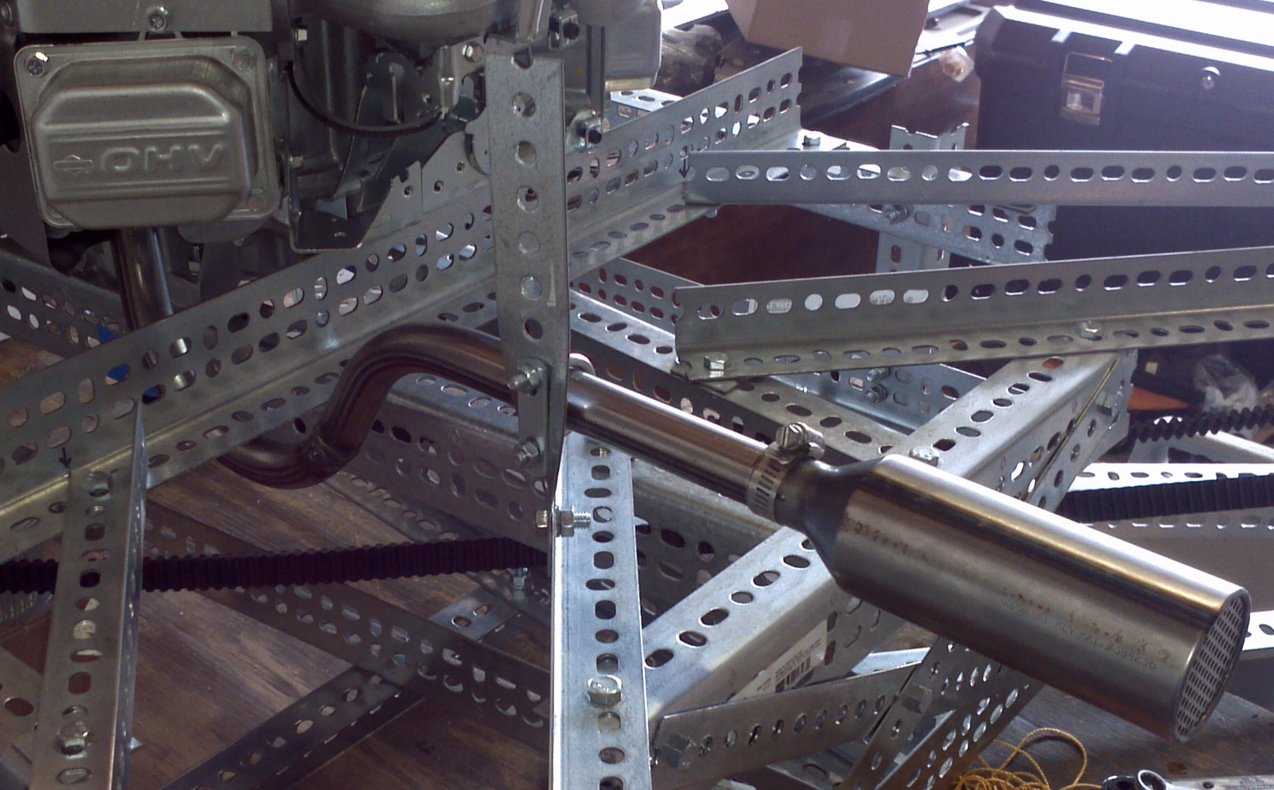
With the exhaust assembled, it was test fit one last time and a bracket was made to support the exhaust. The bracket was made by twisting a piece of flat slotted steel and a U-bolt was used to mount the tubing.
![]() A coat of high temperature primer and paint was added to keep the steel from rusting.
A coat of high temperature primer and paint was added to keep the steel from rusting.![]() The exhaust was then bolted back onto Goliath for the final time. You may notice that the exhaust isn't symmetrical. When I was fitting the exhaust on the starboard side, I accidentally placed the pipe on the wrong side of the bracket and welded the flange at the wrong angle. It'd be a lot of effort to rework it, so I'm going to leave it for now and fix it later if it becomes an issue.
The exhaust was then bolted back onto Goliath for the final time. You may notice that the exhaust isn't symmetrical. When I was fitting the exhaust on the starboard side, I accidentally placed the pipe on the wrong side of the bracket and welded the flange at the wrong angle. It'd be a lot of effort to rework it, so I'm going to leave it for now and fix it later if it becomes an issue.At this point the only things keeping us from testing out the engine is getting the fuel and electrical hooked up to it. I'll talk about the initial electrical system next time.
-
Hackaday Blog and More Progress on the Propellers
06/21/2014 at 13:45 • 3 commentsIf you haven't seen it yet on the blog, Hackaday wrote a great article on Goliath! Thanks to everyone so far who's followed, skulled or posted some of the great feedback.
This weekend I'm cutting the latest version of the propellers (see below). If all goes well I hope to have all four cut by the end of the weekend. I decided to stick with fiberglass for the first set of props since it's about 4 times cheaper than the Kevlar I was going to use. It'll be heavier, but weight isn't an issue yet. The fiberglass should arrive on Wednesday, so doing the layups will be next weekend's project. After those are done, it won't be too long until the first test flight!
![]()
Also I've setup a github account to start sharing the project files at https://github.com/mccloudaero/goliath-quadcopter. I'll start uploading the design files as I complete them.
-
Makining the Propellers and Deciding on Controllers
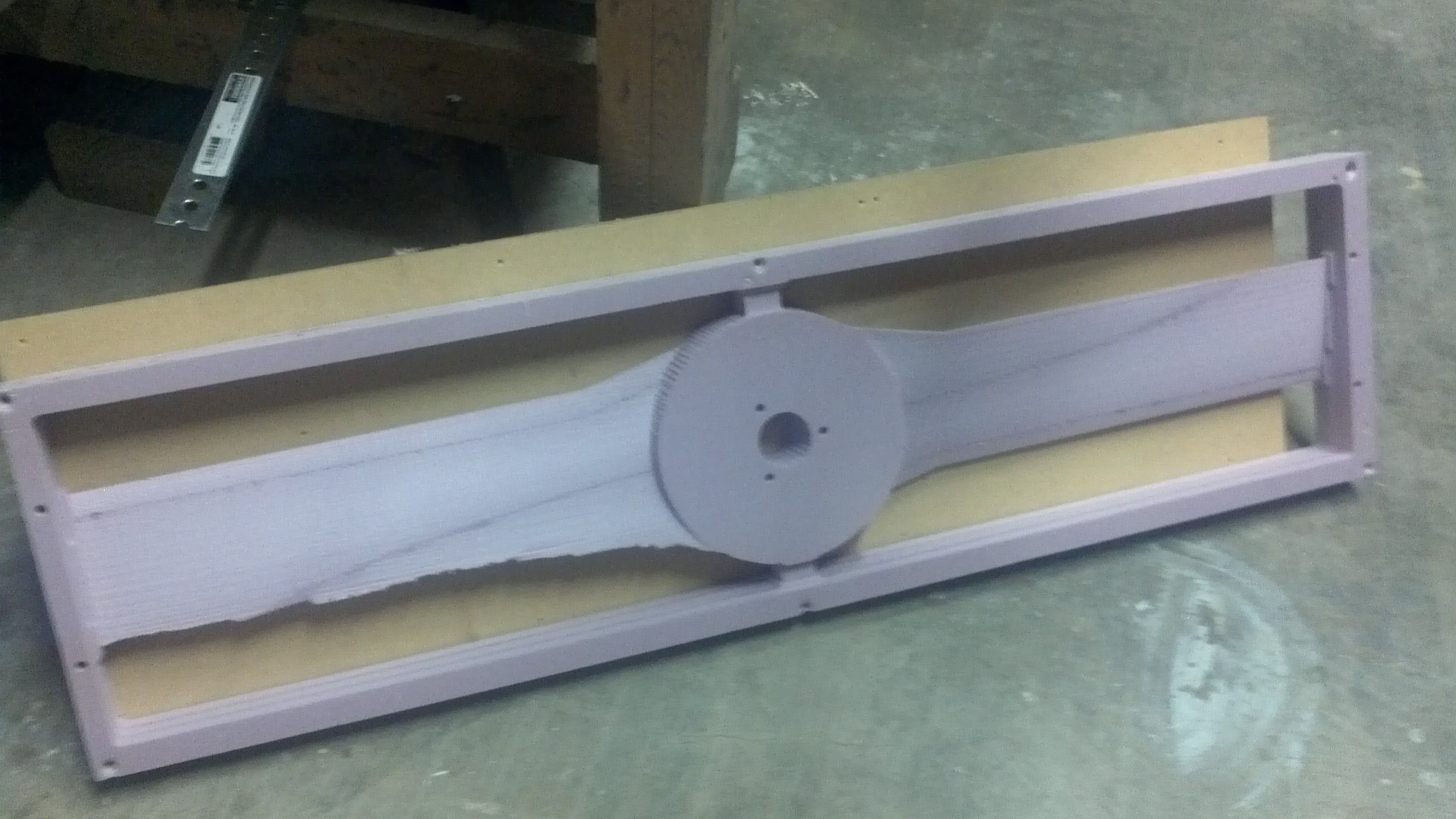
06/16/2014 at 03:08 • 0 commentsProgress has been somewhat slow the last two weeks. Machining the other side of the propeller, went well and it was exciting to have a full scale propeller in hand!
![]()
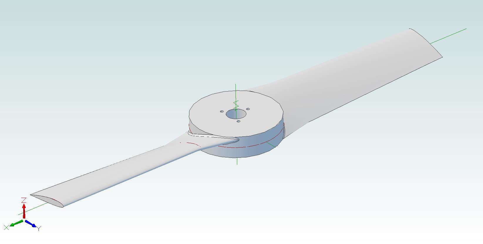
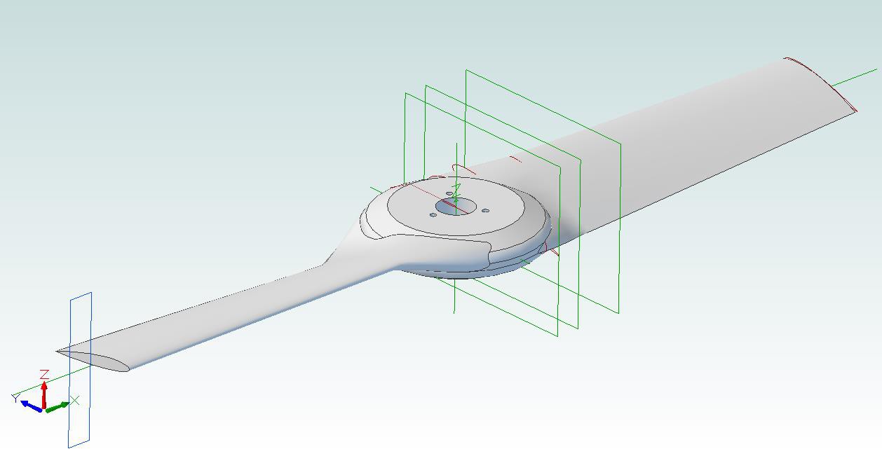
However, having it in hand and thinking in detail about the next step, applying composites over the foam, I realized it would be rather difficult to fit the cloth material over the sharp edges of the hub and that the hub needs to be redesigned. At that point the computer I use for CAD and CAM went bad which brought the project to a standstill. I just got that fixed and now I have a new hub design with a much smoother transition that should be easier to apply the composites over. Hopefully the new design will be machined in the next few days.
![]()
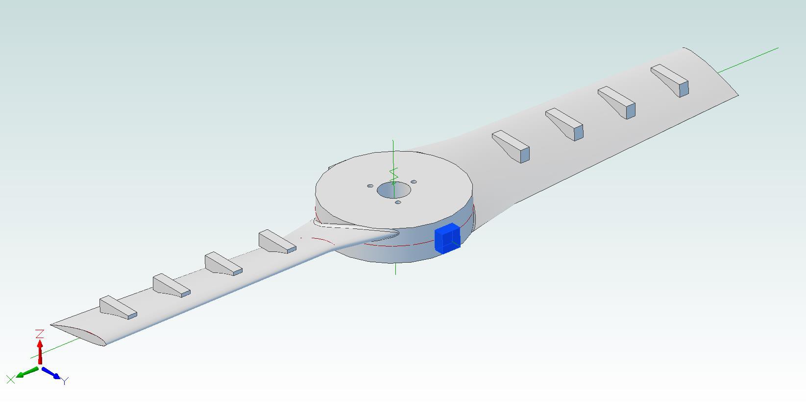
Meanwhile, I've been researching the controls, and what controller to use. For the first iteration of the design I'm going to use 2 vanes under each propeller for directional control. This will require a total of 8 servos, plus one more for the engine throttle.
As for the controller, the Hackaday article on controllers, was an excellent starting point. After looking at all the choices, I decided to go to the Pixhawk controller which will handle all the servos needed. If anyone has experience with the Pixhawk and if there's anything I should know about it before using it for Goliath, I'd welcome any inputs. Hopefully I'll start ordering controller parts this week.
-
Belts and Pulleys (March to April)
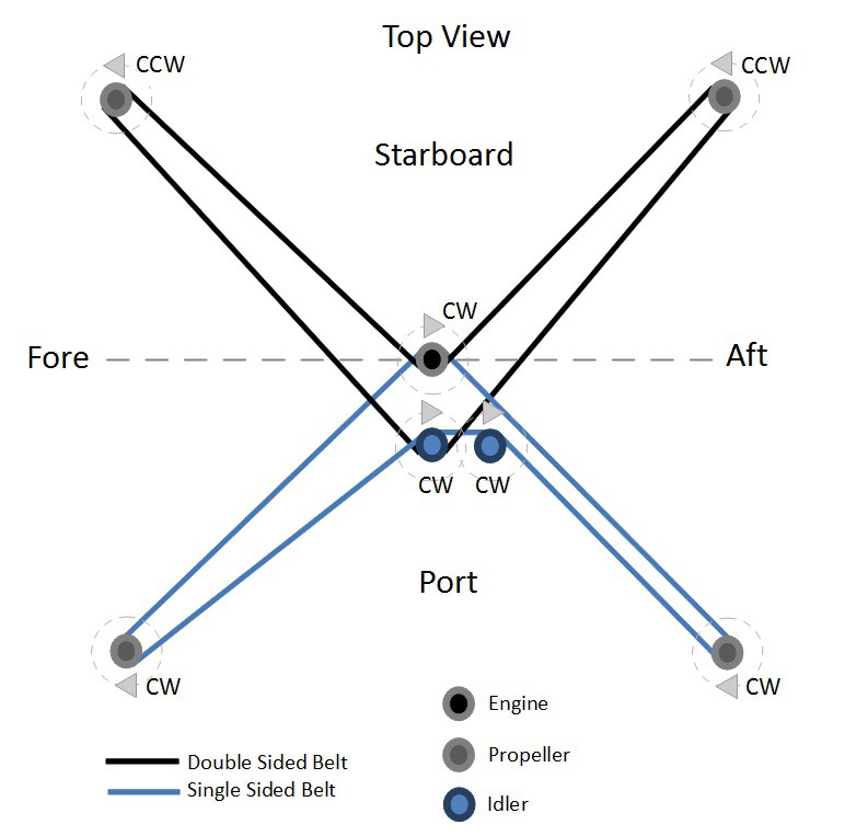
06/14/2014 at 04:32 • 0 commentsAfter completing the frame, the next step was building the drive system. Quadcopters traditionally use 4 individual motors with two spinning clockwise and two spinning counter clockwise to balance out the torque. Since Goliath uses a single engine, the drive system not only has to distribute power to each of the props, it also has to balance out the torque.
A belt system was chosen early on after considering the horsepower and speed requirements. In particular, the belts are HTD, with an 8mm pitch and 20 mm width. One single sided belt turns two of the propellers in the same direction as the engine and a double sided belt is used to turn the other two propellers in the opposite direction. Two idler pulleys, one for each belt are used to tension the two belts.
![]()
The first step in building the drive system was to attach the main pulley to the engine. This is a 50 mm wide pulley directly mounted to the engine shaft with a shaft key. A 50 mm wide pulley was chosen to fit the two 20 mm belts with a 10 mm gap between them.
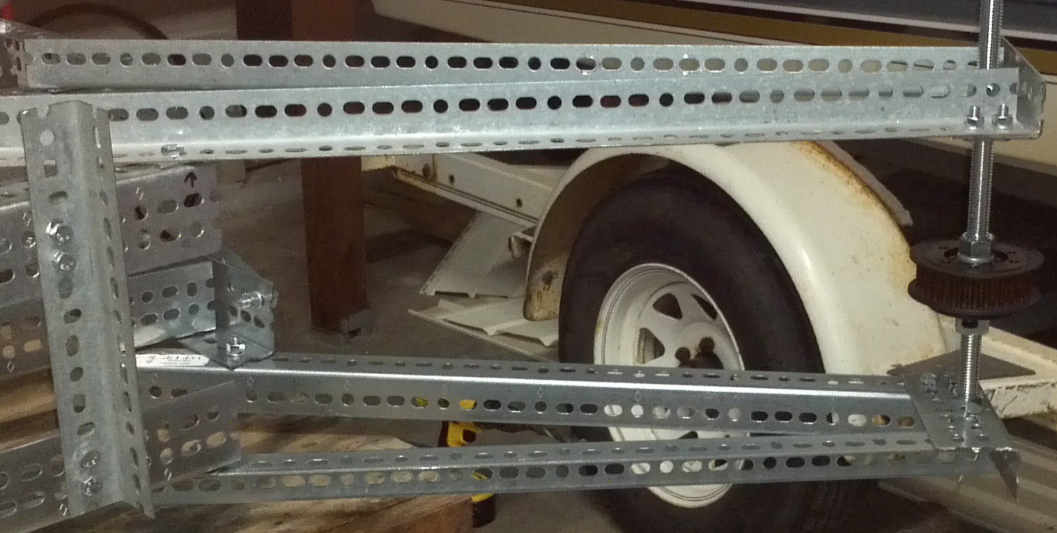
The next step was to assembling the shafts and pulleys for each rotor. The pulleys are mounted to a drive shaft using a ball bearing bushing. The drive shaft is simply 3/4" all thread and is bolted to the upper and lower support arms. Later, each propeller will be bolted to the pulleys.
![]()
Once the engine and propeller pulleys were mounted, a piece of string was used to measure the required belt sizes and lay out the location of the idler pulleys.
![]()
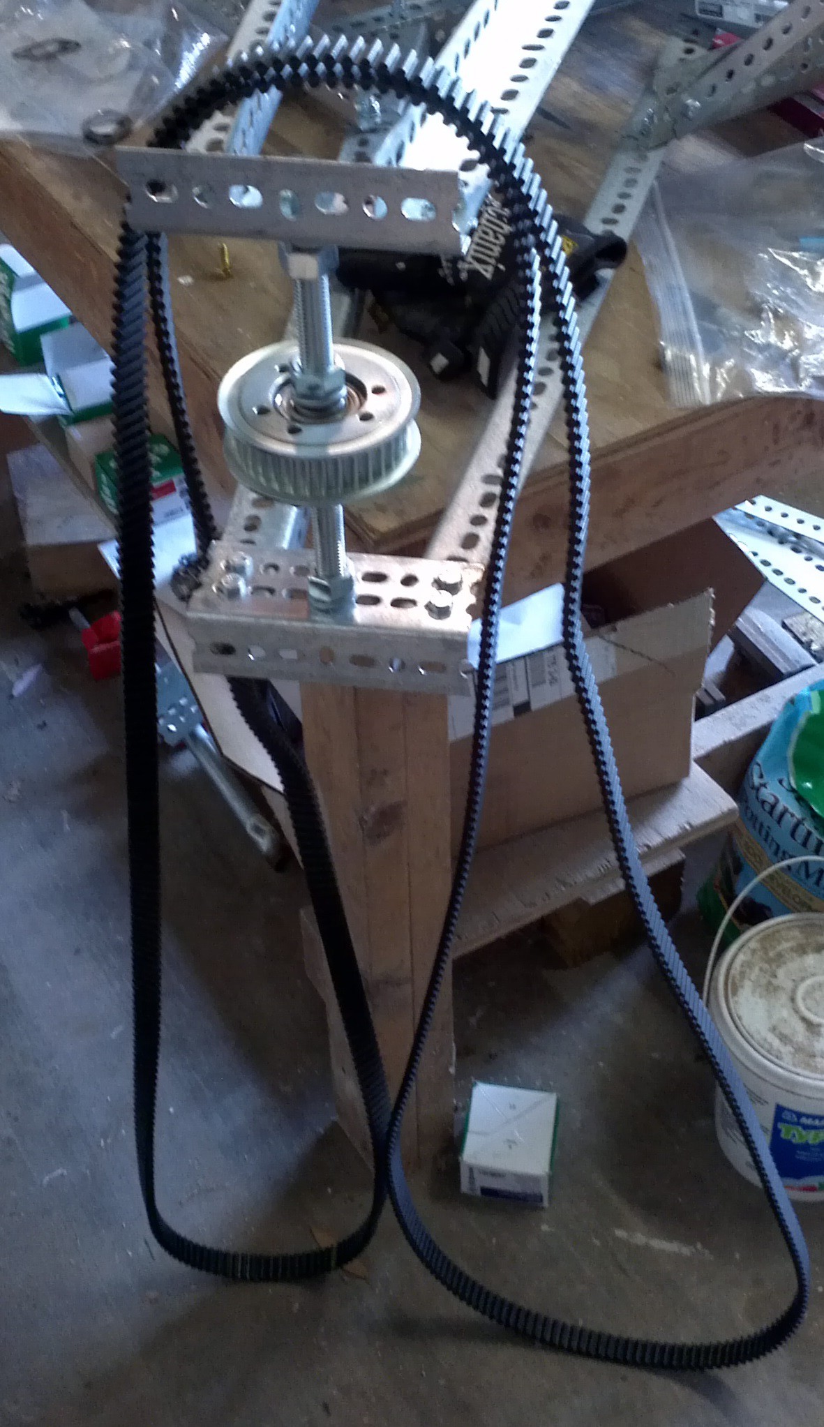
When researching HTD belts, it was surprising to find out how much power they can handle. The strength is due to the continuous length of cord inside the neoprene rubber. The downside to this design is that the belts come in set lengths and splicing them will severely reduce the load the belts can handle. So after measuring the belts, the next biggest size length was selected and the locations of the idlers were chosen to take up the slack. Shown below is the double sided belt.
![]() The idlers are mounted onto 3/4" square steel tube and rotate about a vertical piece of 3/8" all thread. This allows the pulley to rotate about the all thread and apply tension to the belt.
The idlers are mounted onto 3/4" square steel tube and rotate about a vertical piece of 3/8" all thread. This allows the pulley to rotate about the all thread and apply tension to the belt.![]()
On the opposite side of pulley, another length of all thread is attached horizontally. This piece is used to set the tension.
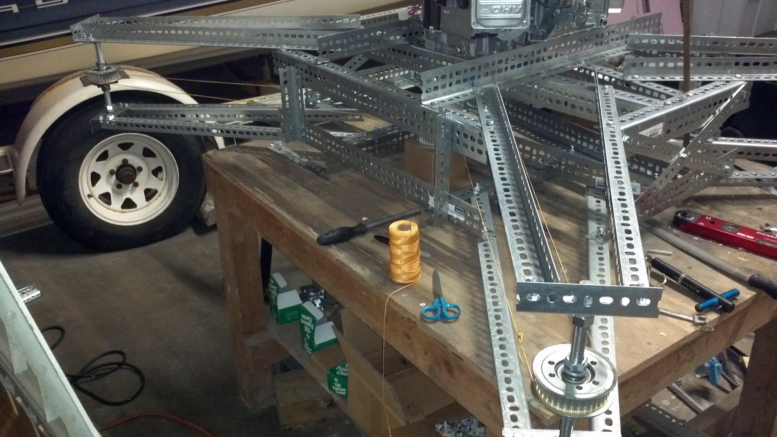
![]() After assembling the idlers, tightening the belts and the making sure the pulleys were aligned, the drive system was complete! If you look closely, you'll see part of the exhaust system being test fit. We'll cover that in one of the upcoming project logs.
After assembling the idlers, tightening the belts and the making sure the pulleys were aligned, the drive system was complete! If you look closely, you'll see part of the exhaust system being test fit. We'll cover that in one of the upcoming project logs.![]()
-
Creating the Propellers (Part 1)
06/02/2014 at 03:56 • 2 commentsMost of this weekend was spent working on the propellers. Goliath was designed with four, two bladed propellers, each three feet in diameter. The were designed using Blade Element Theory for the specific RPM and loading Goliath is expected to experience.
![]()
The propellers will be made with foam cores covered with composites. The foam cores are created using a CNC Router which isn't a straight forward process because the part needs to be machined on both sides. To do this, supports are needed to hold the part in place while machining the backside. This could be done using the CAM software, but more detailed supports can be built using the CAD software.
![]()
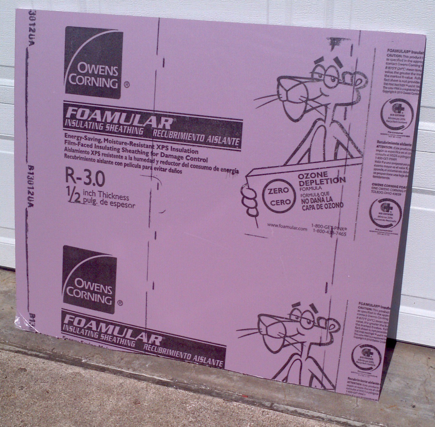
With the supports added, the CAD file was loaded in the CAM software (MeshCAM) and the tool paths were created. With the software side completed, the next step was creating the foam blanks. The foam blanks are made out of styrofoam sheets available at most any hardware store.
![]()
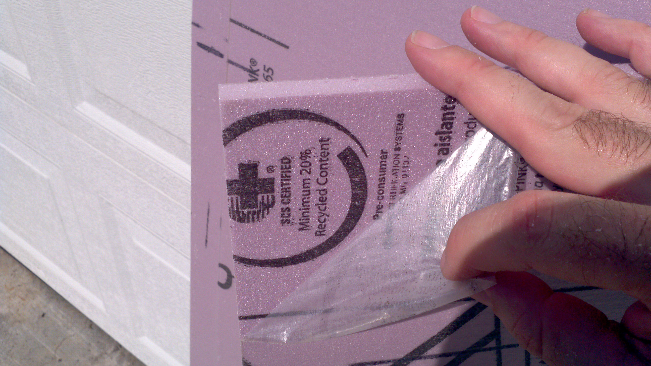
Three 38" x 10" pieces are cut and the protective coating is peeled off of both sides. It's important to do this because the coating doesn't cut well and can get wrapped around the router bits and ruin your part.
![]()
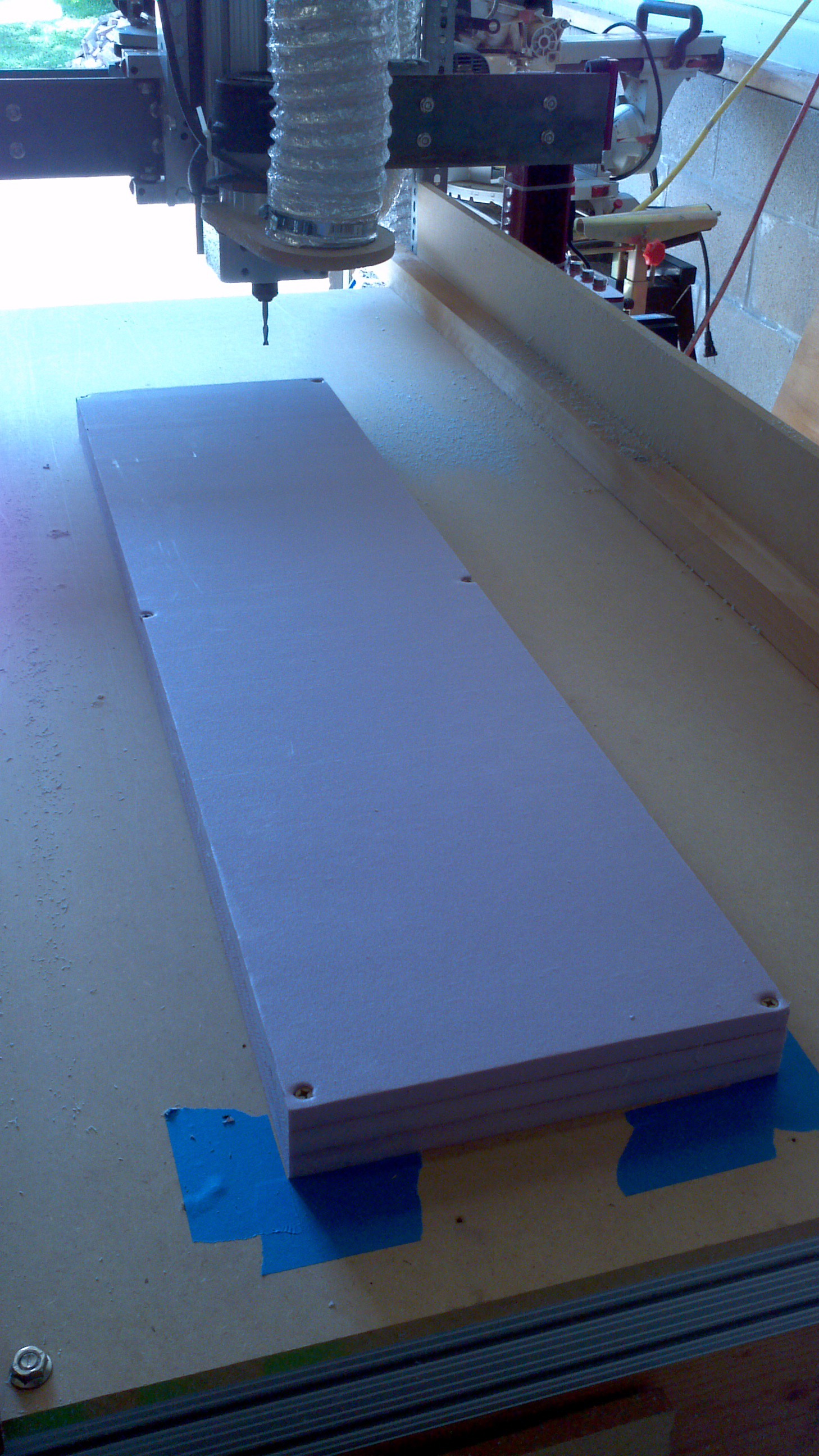
The three sheets are sprayed with adhesive (For this block, Loctite medium hold was used) and glued together to make one larger block. Note the label on the original sheet that says 1/2" thick. These sheets are NOT 1/2" thick. Even with the coating removed, the three sheets have a total height of 1.75". This is the thickness the propeller was designed to. With the block glued together, it was mounted onto the table with 6 wood screws and was ready to cut.
![]()
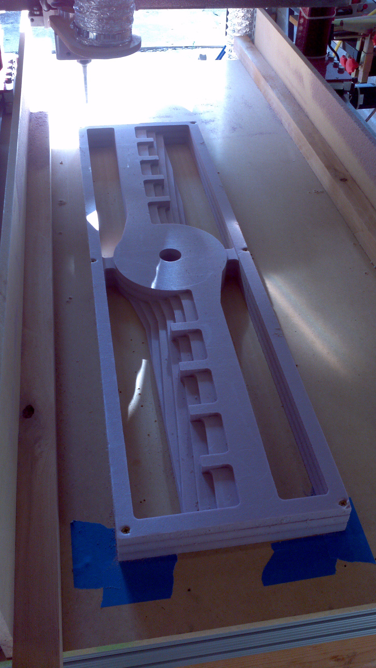
A roughing pass was done using a 1/2" straight bit with 1/4" deep passes. Probably could have been more aggressive since the foam was easy to cut, but the process is still being refined. the results of the roughing is shown below.
![]()
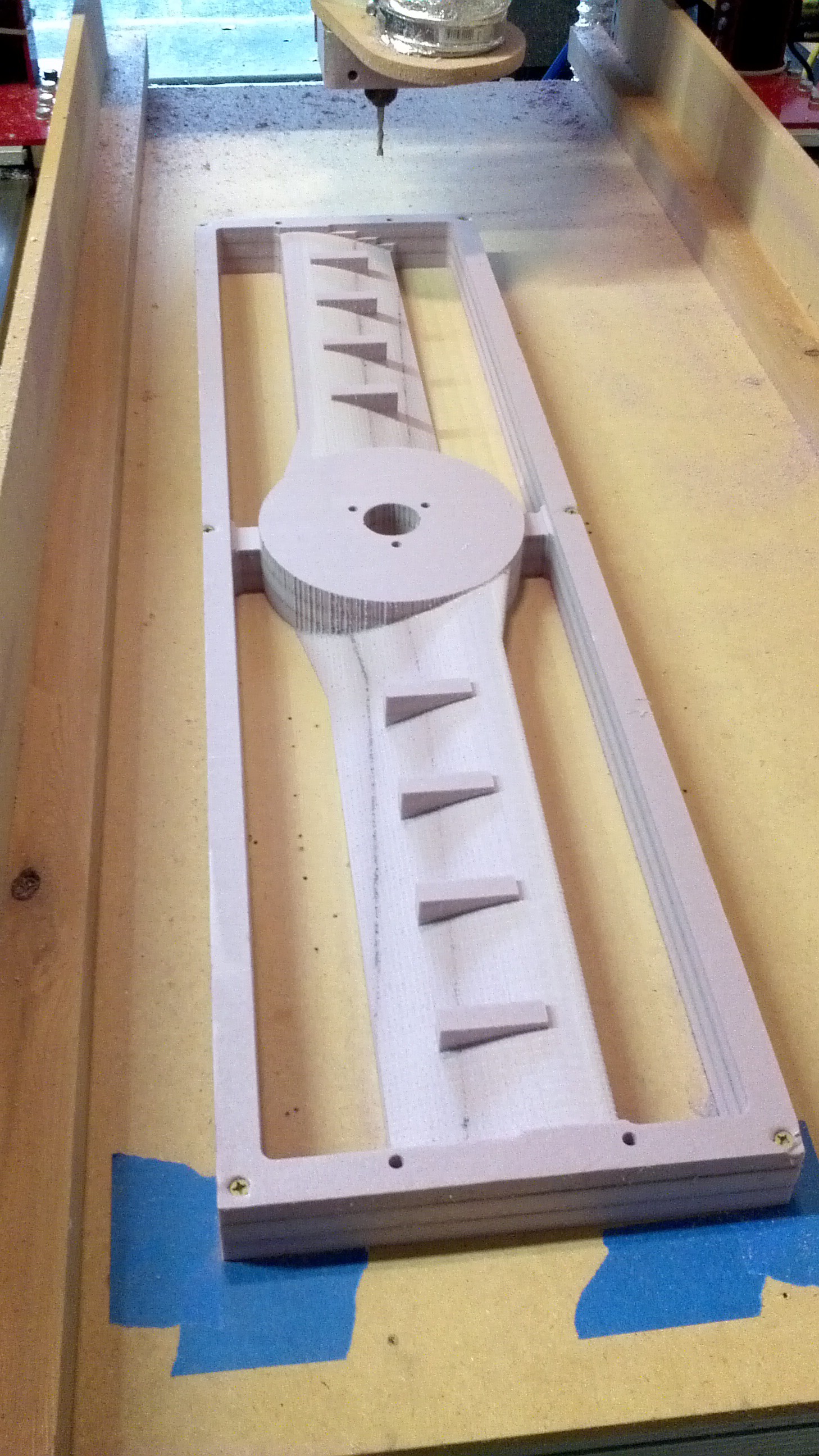
With the roughing complete, a few finishing passes were made. Both an X and Y parallel pass were made and a pencil operation to clean up some of the surfaces. The last operation was to drill the mounting holes and some extra alignment holes at the ends of the propellers. All of this holes will be used to align the part when it's flipped over to machine the other side.
![]()
The part was then removed and the alignment holes were drilled into the spoil board. The part was then flipped overand wood dowels were then used to align the part and to help hold it in place.
![]()
That was all the progress made this weekend. The next steps will be machining the backside and starting the process of adding composite reinforcements to the core.
-
Designing the Frame (February to March)
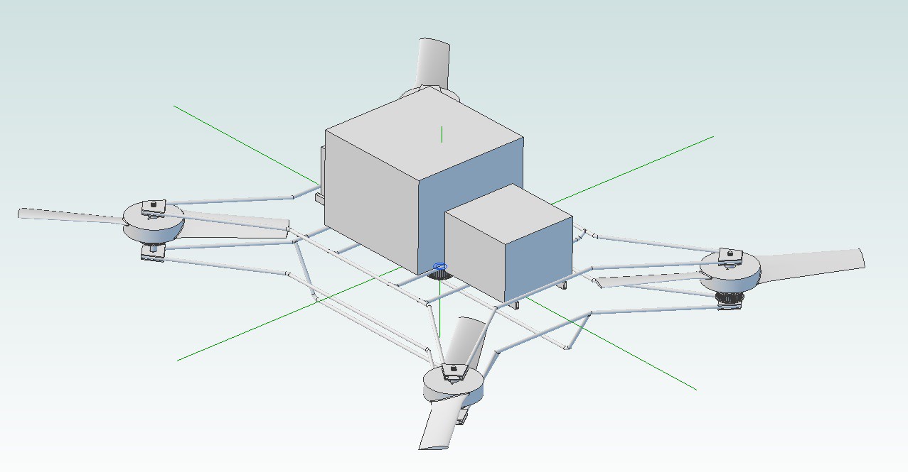
06/01/2014 at 04:21 • 0 commentsAfter picking the engine, some preliminary design work was done to estimate the total weight of Goliath and what type of structure might be required. After using some conservative estimates for the various components and assuming a steel tube frame, the total weight of the quadcopter was estimated to be 240 lbs. Heavy, but still within the capabilities of the motor. An early CAD drawing of the quadcopter with the steel tube frame is shown below.
![]()
The layout was designed to not only support the components, but to also encompass the belt system. This will protect the belts from external objects and help to keep a broken belt from flying outside of the frame.
However, after getting the engine and starting to lay out the structure, it was clear that adjustments were going to have to be made along the way. A steel tube frame wouldn't be the easiest to modify, so a switch was made to slotted angle steel assembled using bolts, both of which can be obtained at most any hardware store and allows the frame to be adjusted as needed.
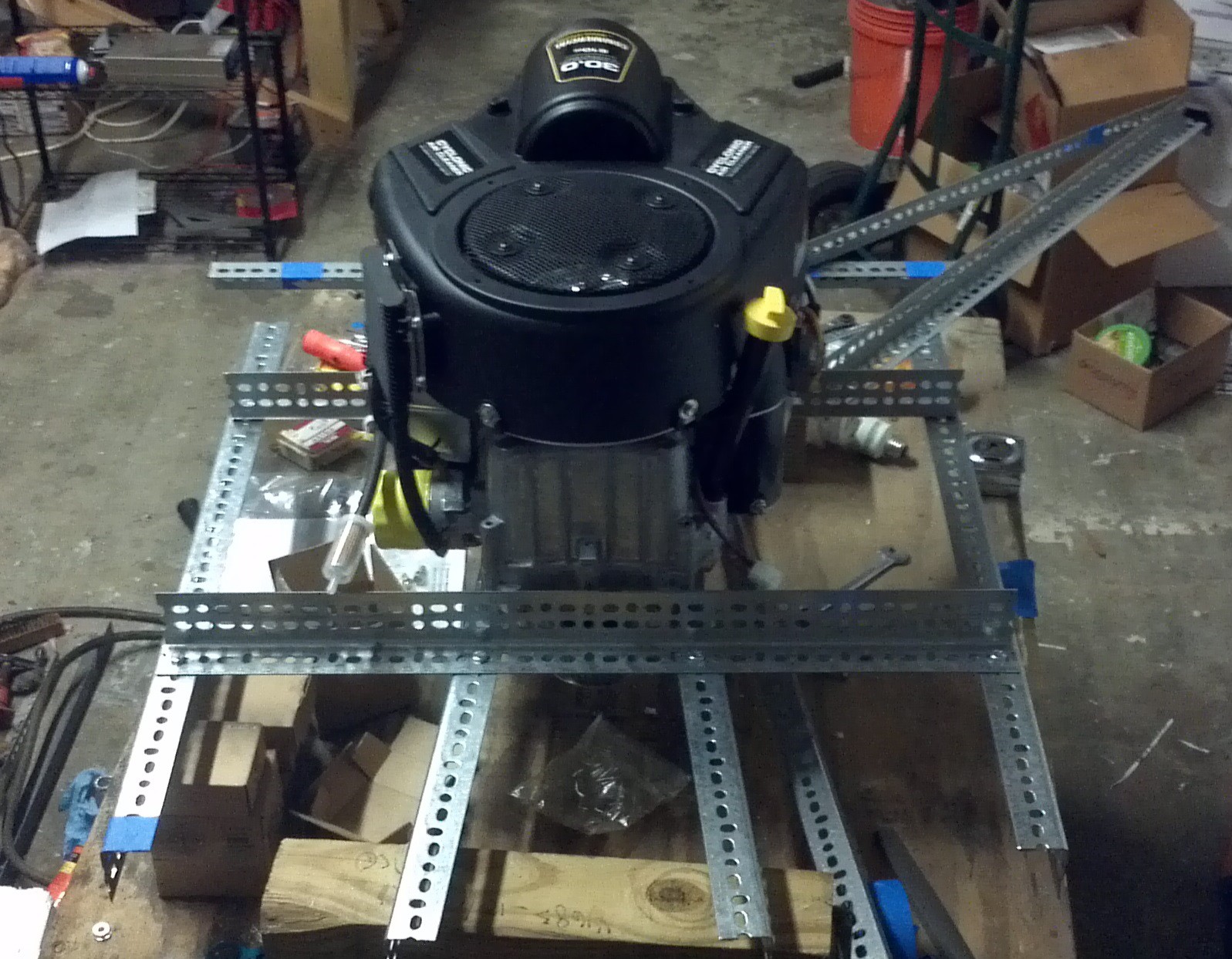
The layout started with the center beams beneath the engine. The weight of the engine required the larger 2 1/2" x 1 1/2" angle pieces versus the smaller 1 1/2" x 1 1/2" angles. The center rails are slightly skewed from front to back, (see the following picture) due to the locations of the engine mounting points.
![]()
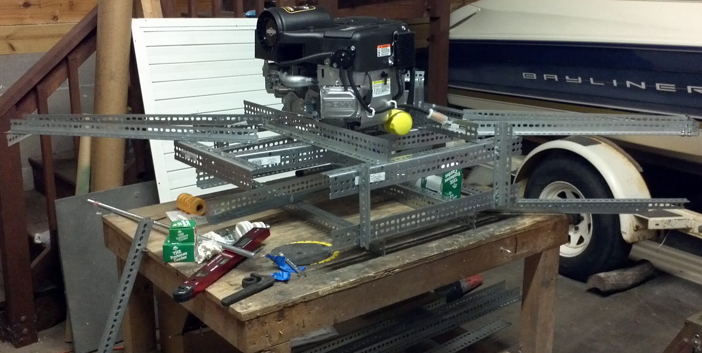
With the top Center Beams in place, one of the Prop Supports was added. However this configuration allowed the frame to flex significantly when loaded.
![]()
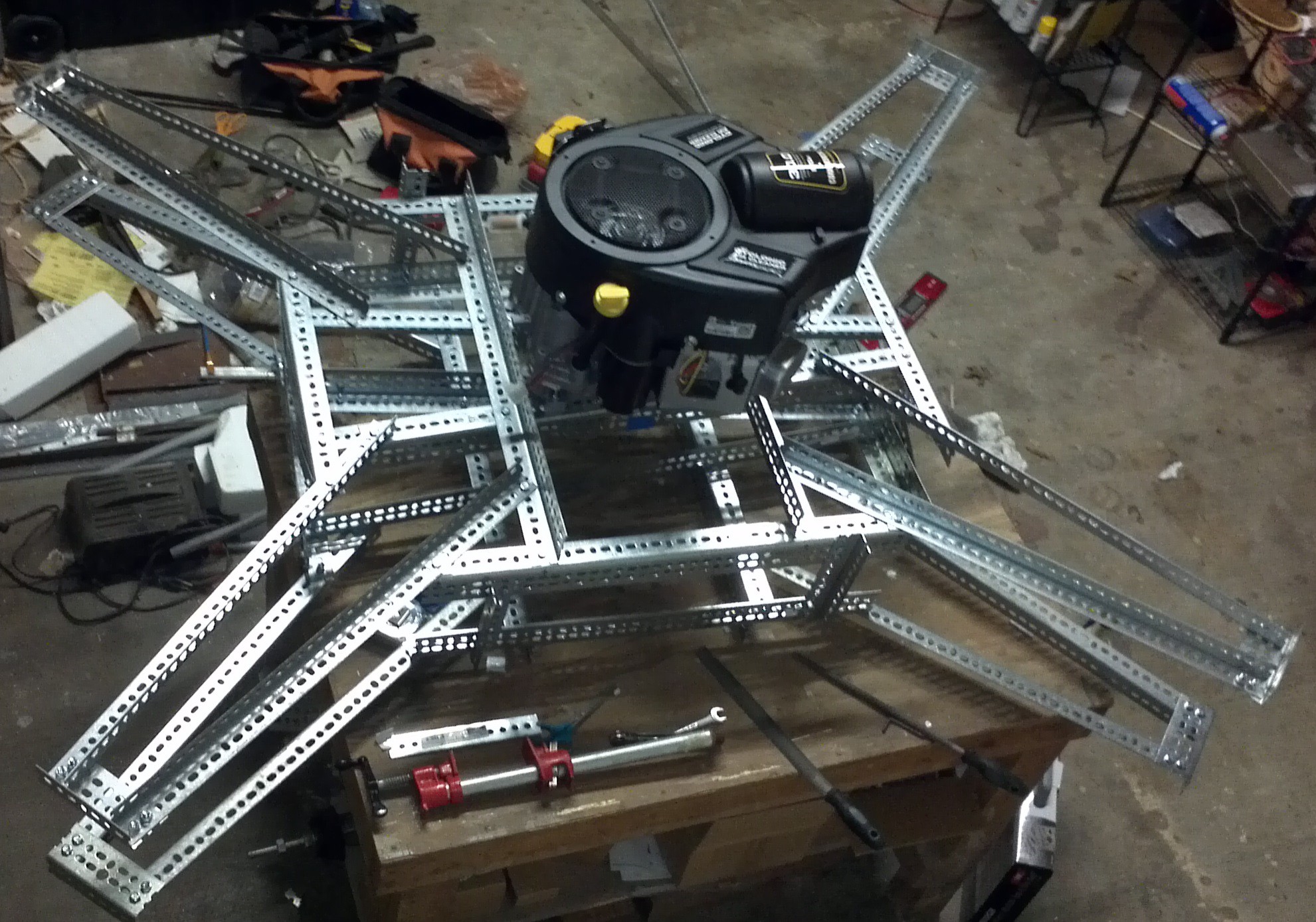
More supports were needed. After trying different configurations, the layout below was used. All of the pieces around the engine are 2 1/2" x 1 1/2" and the Prop Support is 1 1/2" x 1 1/2". After applying some test loads, the flexing was found to be much less.
![]()
With the layout around the engine decided, a duplicate was built and placed underneath it to build a cage for the drive belts. Some short pieces of 1 1/2" x 1 1/2" angle was used to connect to top deck to the lower deck.
![]()
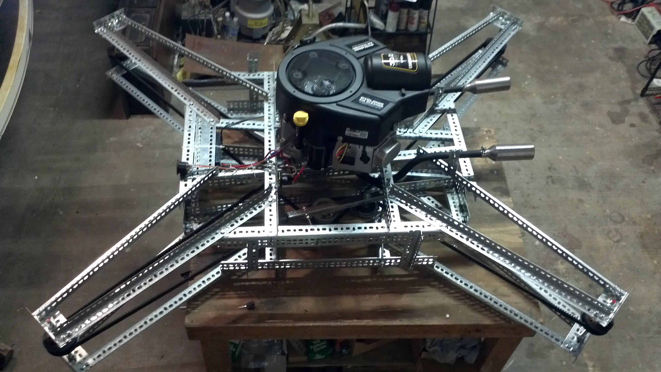
Finally all of the Prop Supports were added and a piece of 2 1/2" x 1 1/2" was added to the end of each Prop Support to mount the prop shafts to. At this point the frame the quadcopter is 7 feet long from corner to corner. The stiffness of the frame is probably less than a steel tube frame would be, but the weight of the assembled frame is about 52 lbs, about what was estimated for a steel tube frame.
![]()
More detailed list of measurements and instructions on assembling the frame will be added later.
-
Getting things started (November 2013 to February 2014)
05/28/2014 at 11:21 • 0 commentsThe Goliath design started back in November of 2013. The project goals were:
1) Build a gas powered quadcopter
2) Use parts that are easy to obtain (as much as possible)
3) Use parts that don't require specialized skills to build (as much as possible)
4) Create a design that could be scaled up.
Prior to starting this project a number of paper design iterations were done, researching various methods of building a gas powered quadcopter. After looking at a number of power configurations (single engine, multiple engines, hybrid gas/electric and a hybrid gas pneumatic) as well as drive train options (belt, chain, gearboxes with drive shafts, etc). For the size of vehicle chosen the best power to weight option was a single vertical shaft gas engine with a belt drive. By using a vertical shaft engine, the shaft is already aligned with the propeller axes and the need for complex gearing goes away. The belt drive has the advantage that it's lightweight, shock resistant and can be easily scaled up.
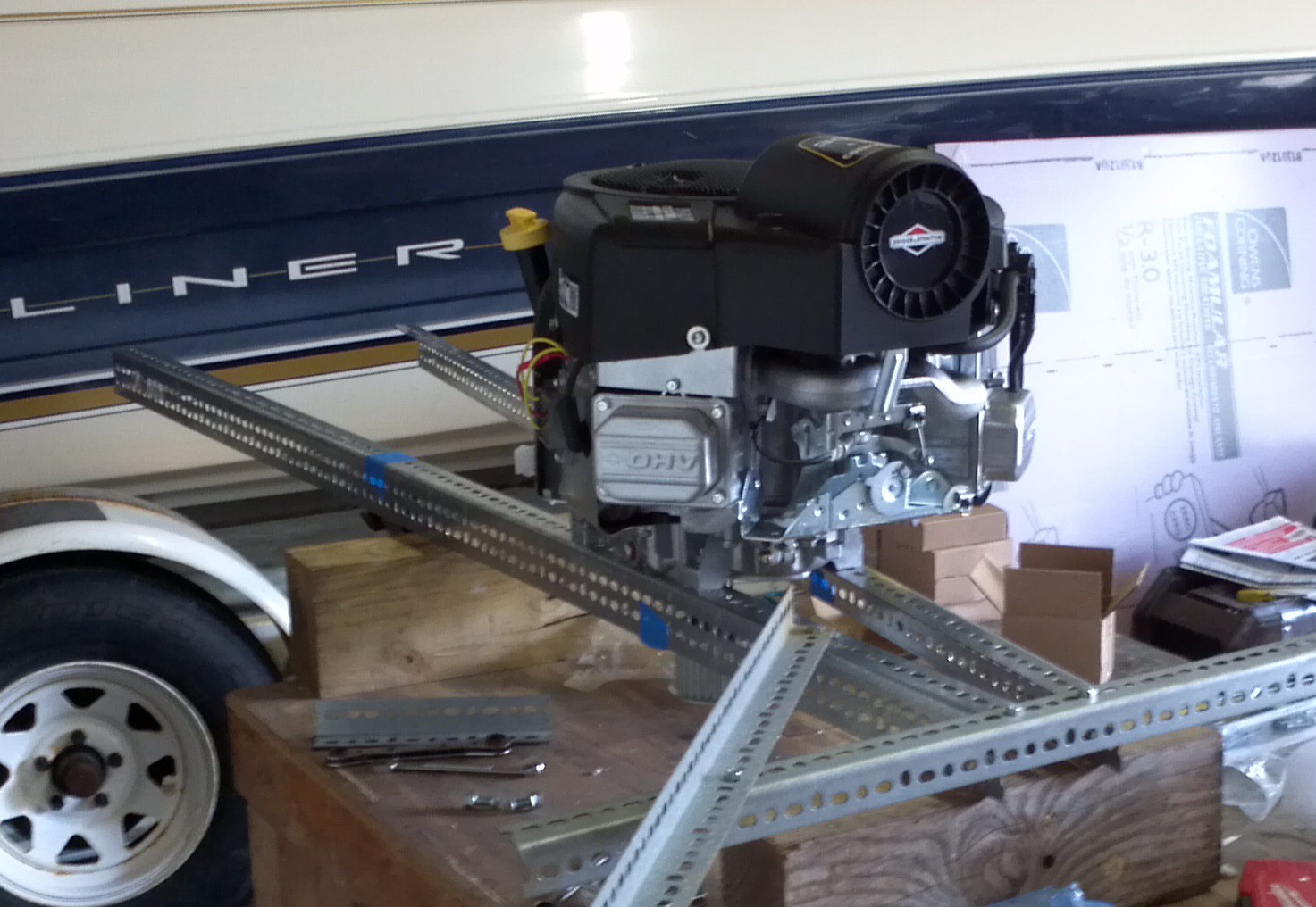
The chosen engine was simply the biggest vertical shaft gas engine I can easily order off the Internet. This ended up being a 810cc 30HP riding lawn mower engine (note: 30 HP is without air filter and exhaust). It comes with an electric starter, and an alternator. Now this engine doesn't have as great as a power to weight ratio as a motorcycle engine (or other engines) of similar size, but it's made to run in the vertical orientation and it doesn't have an integrated transmission/clutch that would make incorporating it into a quadcopter more complicated.
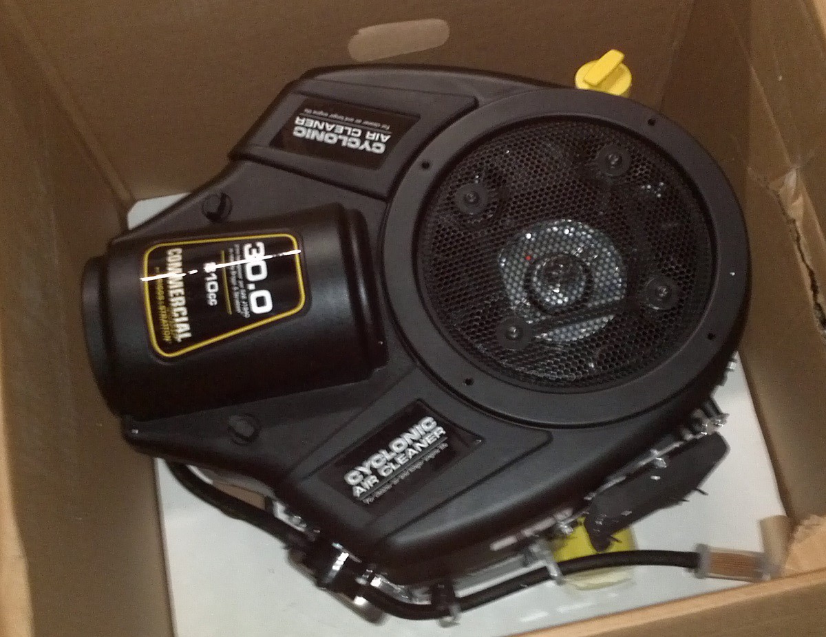
After doing some part selections and creating an initial design in December and January. The engine was ordered and arrived in early February.
![]()
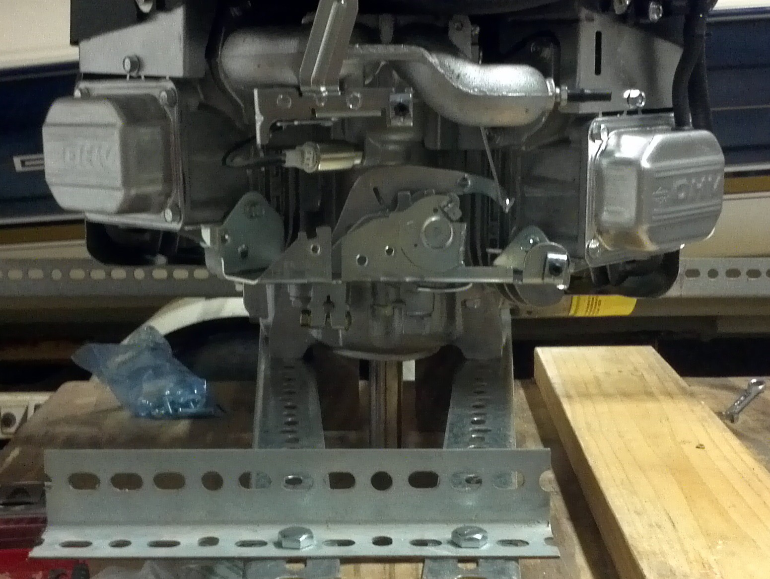
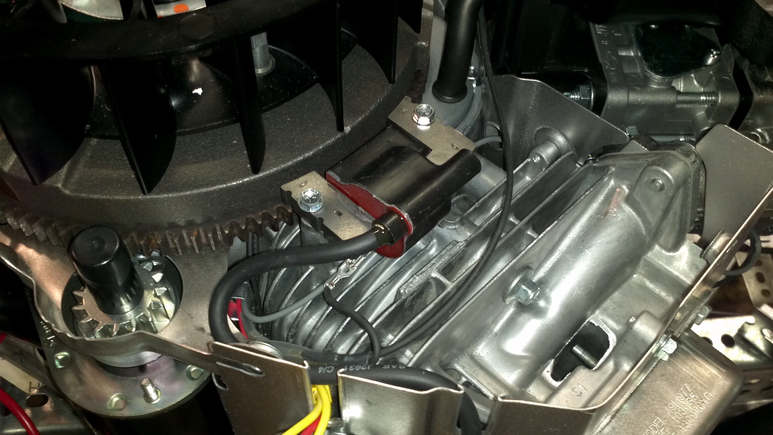
The engine documentation leaves something to be desired. It's marketed as a direct replacement and there is no notes on the required fuel, electrical or exhaust connections. The fuel was simple enough since it's labeled on the tubing that it's 1/4" and the exhaust comes with a gasket that could be measured to find the right parts. The electrical took a bit more research. There were three wires on the engine that all come to the harness. Power from the alternator coming off the regulator, the ignition coils and a fuel shutoff solenoid. After doing some searching I came across two electrical diagrams, both with different wire colors and neither matching the wire colors on this particular engine. It was time to remove the top cover and take a look inside.
![]()
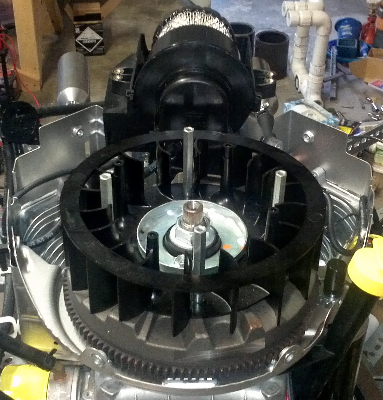
Getting the cover off was a simple process. First the air filter was removed and the oil cooler was unbolted. Next the screen for the engine cooling air was removed and then there was just a few bolts on the cover. Once inside the wires were easy enough to trace back to various parts. Red was the power from the regulator, black was the ignition coils and gray went to the fuel shutoff solenoid. This will be noted on the wiring diagram that will be posted later.
![]()
With the engine in hand it was time to start building the frame around it. That'll be covered in a later post.
-
Current Status of the Project
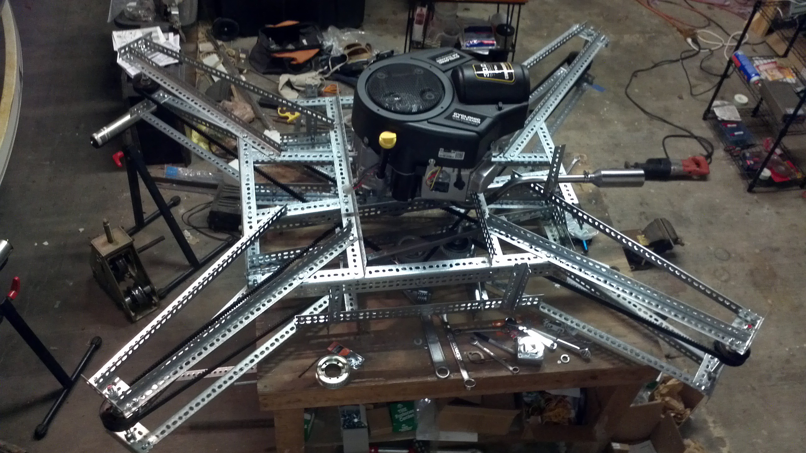
05/27/2014 at 12:17 • 2 commentsBefore documenting the previous steps, it seemed like a good idea to show where the project is at:
![]()
Currently, the frame is assembled from galvanized slotted steel and bolts. This method was chosen over steel tubing or composites to speed up the prototyping process. It will likely need a couple more cross members to increase the stiffness, but it's close to being complete. The vertical shaft engine has been installed and the drive system is assembled with all of the belts, pulleys and tensioners in place. A custom exhaust system was built using go kart hardware. Also installed is a simple electrical system consisting of a small motorcycle battery just big enough for starting since the engine comes with an alternator.
The drive system has been tested by turning the engine over with the starter for a few seconds at a time. What's not complete yet is the fuel system, propellers, ducting and controls and the electrical system will need to be completed for the controls.
The next steps are completing the propellers and adding controls for the throttle. After those items are complete, The quadcopter will be tethered a small distance off the ground and the gas engine run for the first time!
In the future we'll add more details about what it took to get to this point in addition to updates as Goliath progresses.
 It didn't take very long to have my first lesson learned. I'm using West System epoxy and I had gone out and purchased slow hardener (206) knowing that it was too hot (Houston during the summer) for the fast hardener (205). I really underestimated the working time I would have with this and it was gelling before I even got halfway through the first layer of fabric.
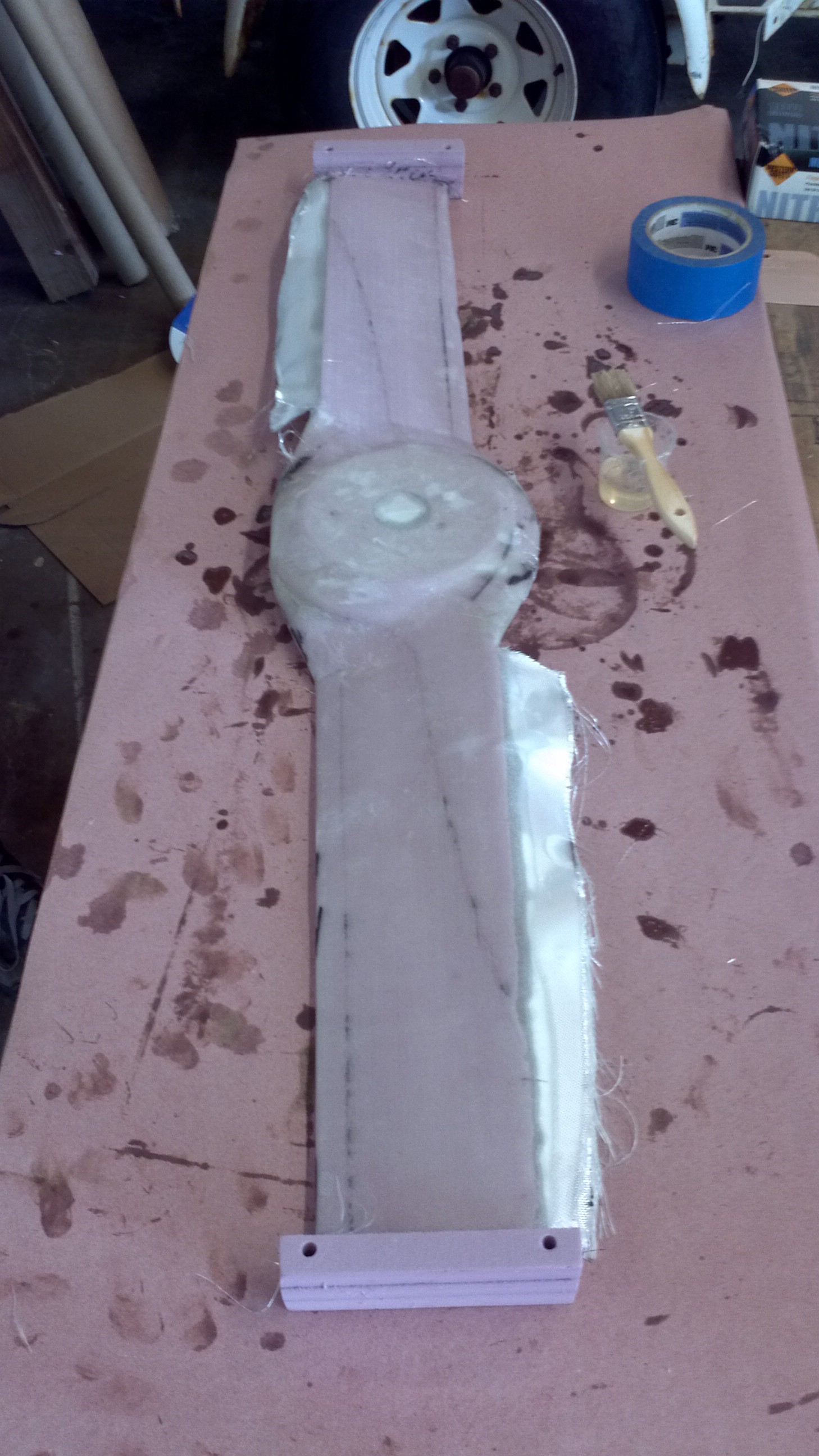
 After trimming off the excess, I started cutting a new propeller. The wood strips didn't seem to affect the routing and everything seemed to be going alright. Then for some reason I haven't figured out yet, halfway through the finish pass on the top side the CNC Router lost sync with the computer. Now I've had this happen on one or two occasions and I just restarted the g-code from the beginning and it'll be fine. This time I decided to restart the cut in the middle of the program, otherwise I didn't have enough time to let it finish before I went to work.
 It's lucky I'm working with foam because if this was anything harder, it would have messed up the machine.
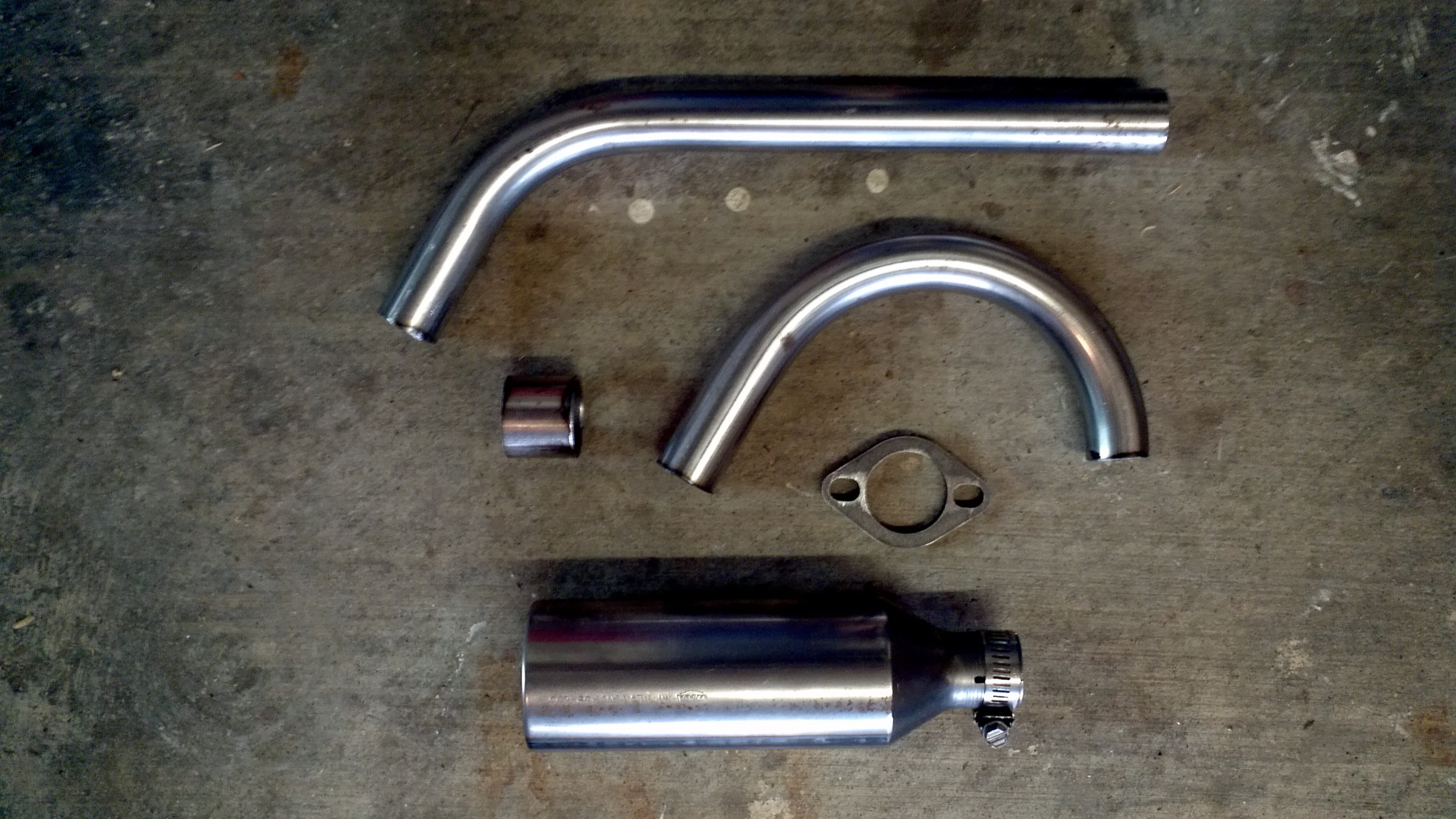
 A coat of high temperature primer and paint was added to keep the steel from rusting.
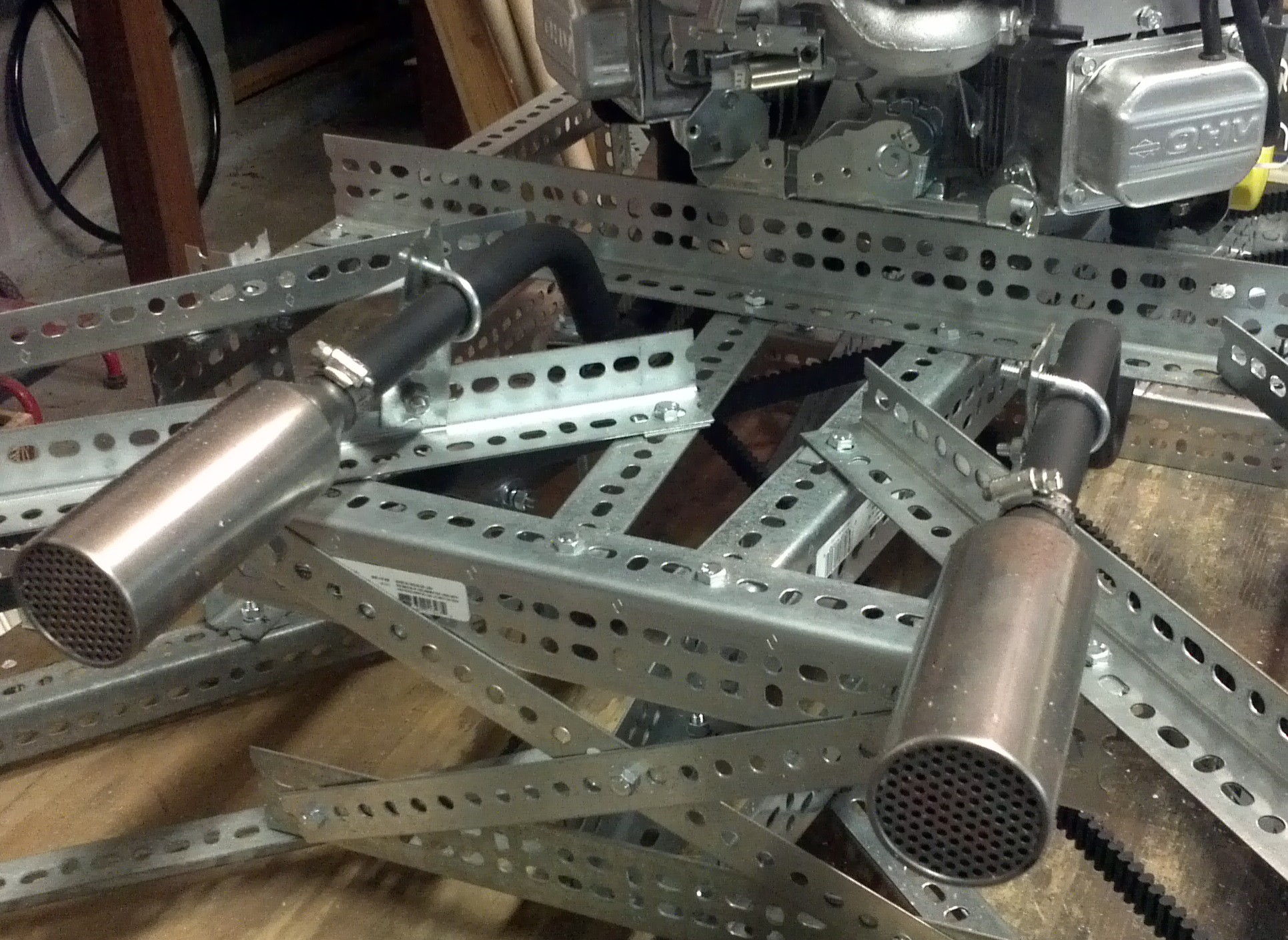 The exhaust was then bolted back onto Goliath for the final time. You may notice that the exhaust isn't symmetrical. When I was fitting the exhaust on the starboard side, I accidentally placed the pipe on the wrong side of the bracket and welded the flange at the wrong angle. It'd be a lot of effort to rework it, so I'm going to leave it for now and fix it later if it becomes an issue.
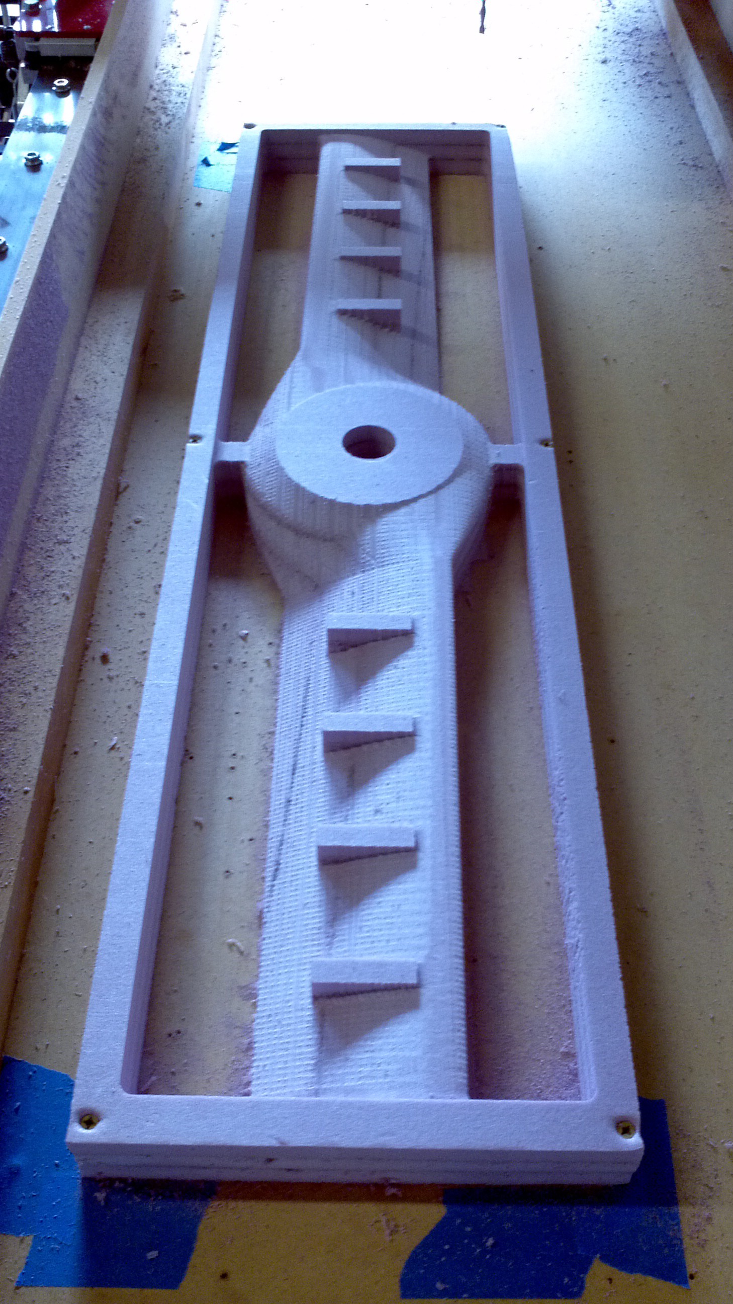
 The idlers are mounted onto 3/4" square steel tube and rotate about a vertical piece of 3/8" all thread. This allows the pulley to rotate about the all thread and apply tension to the belt.
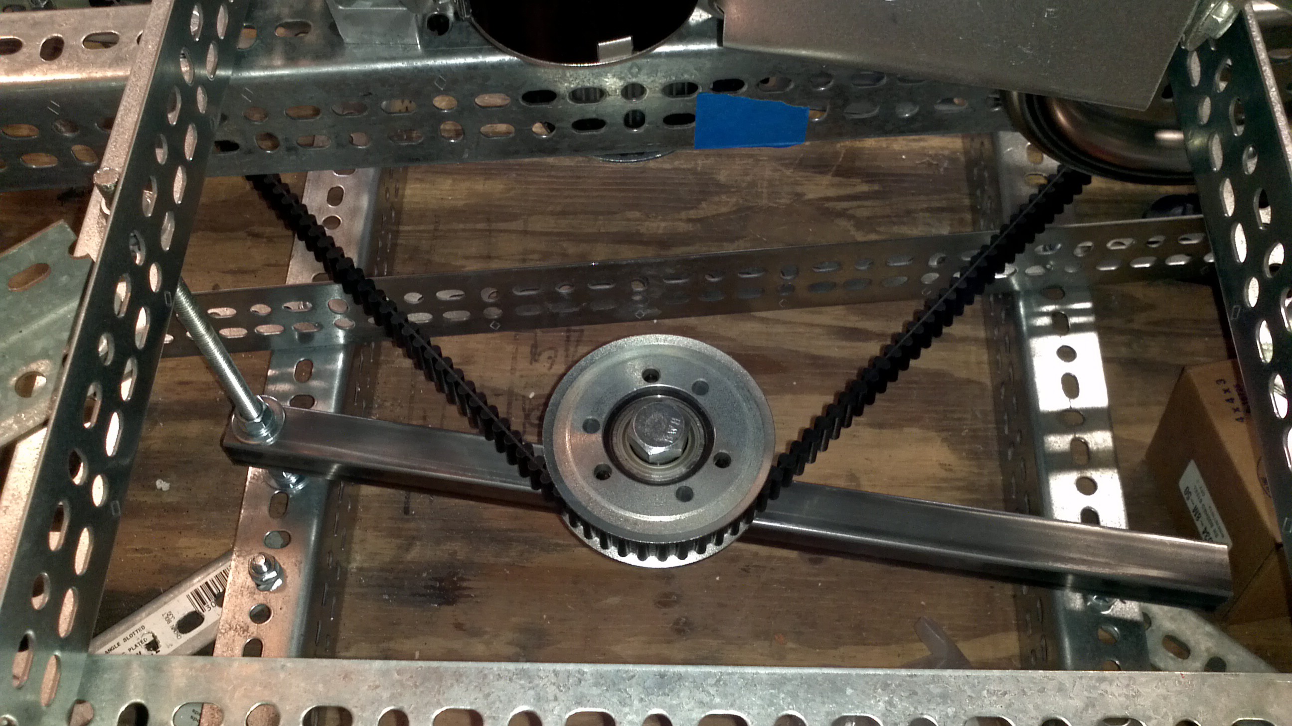
 After assembling the idlers, tightening the belts and the making sure the pulleys were aligned, the drive system was complete! If you look closely, you'll see part of the exhaust system being test fit. We'll cover that in one of the upcoming project logs.