Close
0%
0%

Diode Laser Etching of a PCB. DIY From a to Z.

If you want to make your own PCB and you've got a 3D printer or DIY, use Diode Laser Etching instead of ironing.

Similar projects worth following
3D-printers have opened endless possibilities for home production and rapid prototyping. Now you can easily create practically any model in a 3D-program and 3D print it. But until now, only few people have thought about the possibility to 3D print electronics for this or that solution (model).
Up to this day to make a circuit board for a prototype one had to pore over it with a soldering iron or to order a short production run. However, many of us can make it using a conventional iron and a laser printer.
https://www.youtube.com/watch?v=GjXhPRYOMzg
Though, this process is not very pleasing either aesthetically or technologically. In this article we would like to describe another method.

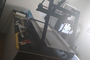
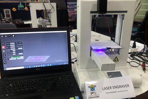
Not only any 3D printer but also any DIY Engraver will fit for it

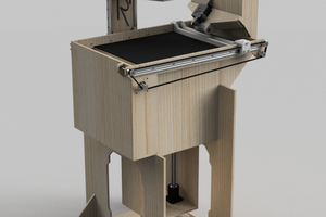
or a constructor of a makeblock plotter xy type

By the way, you can install a diode laser almost on any 3D-printer, setting it as an addition or in place of the extruder. Diode lasers are small in size and compact. Their relatively small power output compared with that of CO2 lasers is not a drawback in this case.

So, what does the process of the circuit board manufacturing at home or in the office look like?

For this we need a copperized glass fiber plate, any dark vinyl film (any dark film that a laser can burn through will fit), iron chloride (sold openly in stores of chemical reagents) and, of course, a diode laser installed on a 3D printer. Its power output is not so very important, but we recommend to use a diode laser of more than 2W (2000 mW).

To install a laser on any 3D printer is very easy …

How to install it on an Ultimaker https://www.youtube.com/watch?v=soYh5Kyv4cs

and on a WanHao DuPlicator i3 https://www.youtube.com/watch?v=yf-uFAynGhM

So, let’s begin. Go to instructions!

  • 1
    Step 1

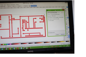
    1. Create a circuit board model using any program of an InkScape type (inversion picture. Later, we’ll explain why inversion).

    2. Convert it into the gcode.

    3. Stick the vinyl film onto the copperized plate of glass fiber.

    4. Place the vinyl coated glass fiber plate onto the work table of the 3D printer, and turn on the 3D printer in the laser cutting / engraving mode.

    5. The laser will burn on the vinyl film an inversion image of the pattern to be resulted.

    6. Dissolve the iron chloride powder in water (do not worry, no chemical reaction will follow).

    7. Put the glass fiber plate into the iron chloride water for 45-60 minutes.

  • 2
    Step 2

    The copper on the glass fiber surface, free of the film after the laser burning, will react with the iron chloride (copper etching chemical reaction) and goes into the solution leaving clean glass fiber in the contours of the inversion image.

    Then, make holes for the necessary connectors with a small drill, or leave as is, and solder the connectors on top of the circuit board.

  • 3
    Step 3

    So, we have told you how you can create a small shop - laboratory for circuit boards manufacturing, using a 3D printer and a laser.

    This technology is certainly not perfect and has several shortcomings, but it is efficient and can be used at home and small laboratories.

View all 3 instructions

Enjoy this project?

Share

Discussions

PointyOintment wrote 07/16/2018 at 01:44 point

Is your "vinyl film" made of PVC (polyvinyl chloride)? PVC is probably the best-known material for not being safe to laser-cut, because it produces chlorine gas that's bad for both you and the machine.

However, I have seen a video on YouTube (from Jeri Ellsworth, I think) of a fume hood that goes directly on top of the material, with a window for the laser beam to shine through, that captures the chlorine gas, making it safer to cut/etch PVC.

  Are you sure? yes | no

Similar Projects

Does this project spark your interest?

Become a member to follow this project and never miss any updates