low-field MRI Continued
An attempt at a prepolarized Earth's-field compressive
magnetic resonance imager
An attempt at a prepolarized Earth's-field compressive
magnetic resonance imager
To make the experience fit your profile, pick a username and tell us what interests you.
We found and based on your interests.
A quick update, with some progress on the magnetic-field-measuring-jig!
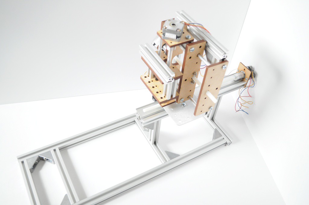
Figuring out a way to measure the magnetic fields inside of the magnet bore has been something I've been thinking and prototyping for a while now. In this case, the task is complicated by:
These unusual requirements have led me through a bunch of unusual design choices and prototypes, from 64-magnetometer imaging arrays to a polar cylindrical cnc system for measuring magnetic fields that I put together last year, that included (among other things) dental floss and elastic bands as the main source of non-metalic, non-magnetic drive components for one of the axes. I think part of the reason why I've made these choices, aside from it being a strange problem, is that I really like to explore how to design and make inexpensive, easily-sourced mechanical systems with rapid prototyping systems like laser cutters. But -- forest for the trees -- as enjoyable as it is to design these, at some point you have to pick a design, and work the rest of the problem.
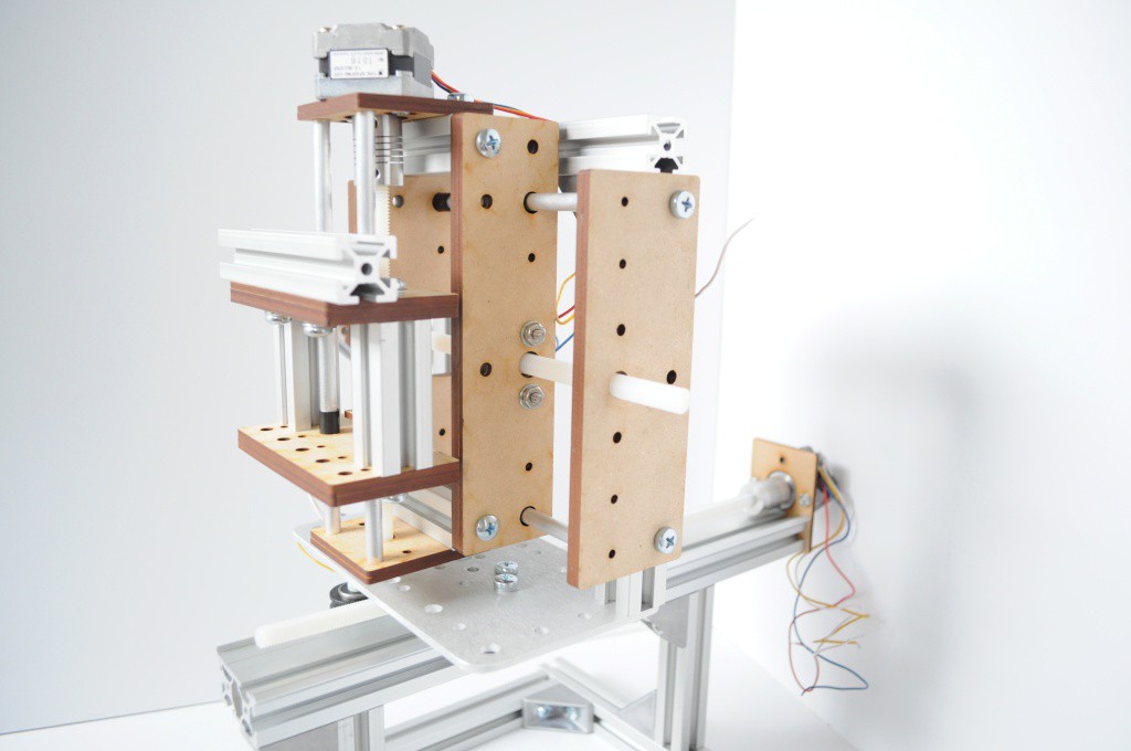
With the design I've settled on, I've tried to keep things as simple as possible given the unusual design requirements. The system is essentially an X/Y table turned on its side, then mounted to a long Z stage. The whole thing is then layed down, and bolted to a supporting frame, that will also include the control electronics for the entire system, as well as the magnet. The magnetometer will mount, so the idea goes, to the outermost axis on the table, on a long stick about a foot or two in length -- as long as possible, while still having the full travel of the bore, plus an inch or two outside to "park" the magnetometer when it's not being used.
Rigidity, repeatability, simplicity and the ability to mount the entire system on one frame drove most of these requirements. All those attempts at an elegant solution -- imaging arrays, polar systems, and in the end it's a magnetometer... mounted on a long stick. Definitely have to laugh at that...
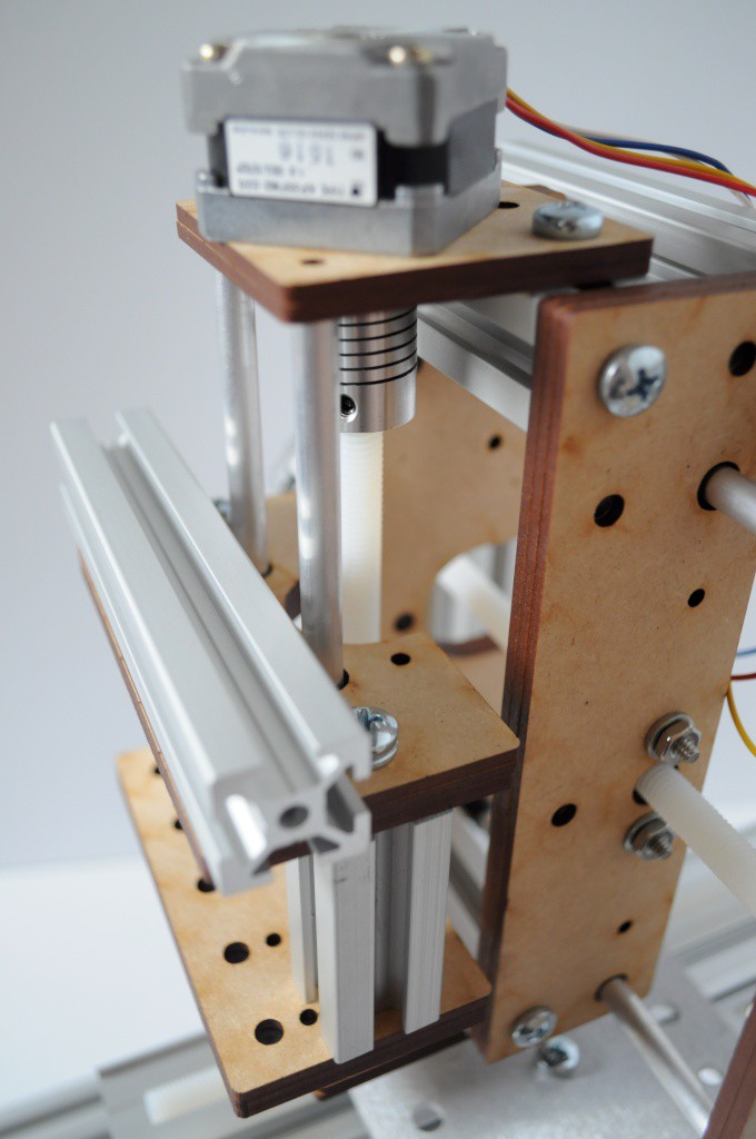
I'm very happy with how these linear axes turned out. The carriages are three pieces of laser-cut MDF, with a cuts that sandwhich 1/4 inch diameter nylon flange bushings firmly in place. The aluminum shafts are 1/4 inch, with what looks to be about a 1-2mm wall. Normally when laser cutting linear axes, I make the entire system out of MDF, but here I decided to add in some pieces of Misumi t-slot aluminum extrusion to increase the rigidity, and make mounting the steppers (and whatever else may need to be mounted) a little easier.
The major partslist for each axis is very minimal:
This places the mechanical bits in about the ~$10-$15 range, which is very reasonable for a short-travel axis that doesn't require a huge amount of precision.
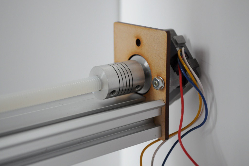
The "Z" axis is simply a single piece that mounts to the end of a piece of Makerslide, and was reused from the coil winder I cobbled together earlier.
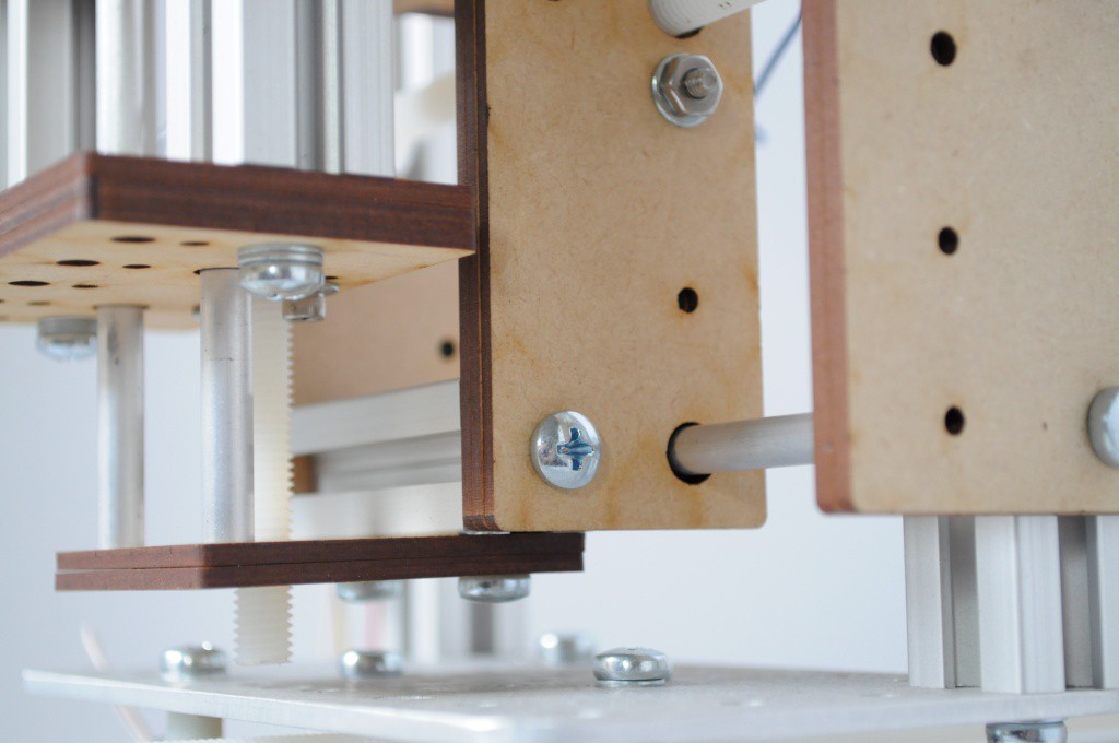
Another vie of the X/Y table. The larger frame is also made of aluminium extrusion, and mounts edge-on to a standard Makerslide carriage plate on the Z axis.
Each of the table axes has about...
Read more »A quick update, with designs for the magnetometer breakout board.
It's been a very busy week in the lab (conference season), so I unfortunately haven't had a great deal of time to devote to much other than data analysis, eating, and sleeping. I've tried to load up my queue so that I can do quick tasks (like create a magnetometer breakout board suitable for measuring the field inside the bore) that have long turn times, like the two weeks that it takes for boards to arrive from the fab. That way, when the dust clears, there will be plenty to get busy with.
I've been itching to connect everything together, place a bottle of water inside the bore, start pulsing the field, and see if I can collect the first proton precession signals. But I've restrained myself, in that everything is currently a jumble on the bench, and the last time that I rushed a delicate system (nearly one year ago), I ended up accidentally blowing up two of the OpenCT2 detectors, and setting the project back a few weeks. Here, I'm extremely anxious about connecting up a nest of wires that has several amps of current pulsing through, so I just have to wait a week or two, until I can laser cut something to properly and safely mount everything.
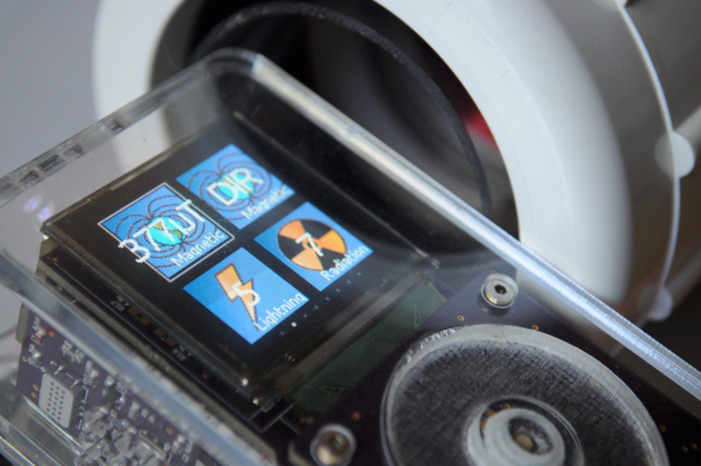
I did get the chance to test out the polarizing coil field (above), and as near as I can tell until I have a magnetic probe that can fit into the small bore, the field is performing as expected. The HMC5883L magnetometer in the Arducorder Mini saturates 5-10cm away from the coil itself, which is a good sign that the field intensity inside is high enough to detect the proton precession signal.
The coil form itself gets reasonably warm after a minute of being on, it essentially being a giant resistor, as if to implicitly warn me that I'm treading somewhat outside my expertise in low-voltage, low-current digital electronics to something that requires serious juice -- and to make my mistakes cheaply. One of the worries that I've had, given that some other folks (like the PyPPM) tend to use the sensor coil both as a polarizing electromagnet and as a sensor coil, is how much of a voltage spike will be carried through the system from having to pulse the coil. I included some clamping diodes on the inputs to the amplifier board, but those are more for accidental overvoltage, and I'd rather not pulse the board with large spikes several orders of magnitude over its sensing range every few seconds, if possible.
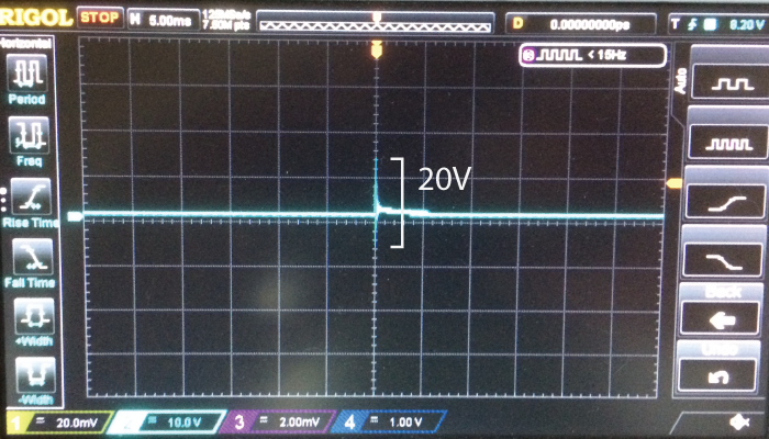
I haven't yet completed the circuit to quickly quench the polarizing field, but viewing the voltage induced on the sensor coil simply from powering on the polarizing coil from a bench supply couldn't be more clear -- even with a relatively small number of turns and the air gap between the polarizing coil and sensor coil, a very large voltage spike is induced, and the sensor coil needs to be connected through a relay that disconnects the coil while the polarizing field is powering up or quenching.

One of the main pieces of the instrument that's left to complete is the volumetric magnetic field measurement apparatus. Last year, I spent a great deal of time on this aspect -- at one extreme creating a board with an 8x8 grid of magnetometers, while at the other extreme I put together a large polar CNC system that contained nearly no metal, used a single magnetometer (and some tensioned dental floss) to scan it through space, and smelled very minty while in operation. In retrospect I think I was enjoying the nonstandard design constraints a little too much, and ended up sketching (in hardware) a variety of prototypes that were a little overkill.
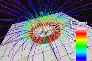
This year, I'm benefited by the happy coincidence that other open source folks have also become interested in magnetic field measurement. Ted Yapo has been doing a beautiful job putting together a magnetic field scanner by simply strapping a magnetometer to an old 3D printer, sparsely moving the 3-axis system around the object, then interpolating the fields to produce some beautiful visualizations....
Read more »A quick update, with two freshly-wound coils.
One of the tasks that I'd completely underestimated the difficulty of when I first began this project is coil winding. On the surface it looks very easy -- just winding a wire around a cylinder, many many times -- but keeping track of the number of turns, making multilayered coils, and keeping enough tension that the whole thing doesn't fly apart and uncoil in a fury of wire and tears (which has happened more than once) is all more challenging than it first appears. That's why it's comforting to feel like I'm finally getting the hang of this whole coil winding thing.
While I'd previously wound my first sensor coil, this was more of a practice coil, and the first multilayer coil that I'd attempted to wind. A proton precession magnetometer (and, presumably, a spatially resolved PPM) generally needs at least two coils: the sensor coil, which receives the very low-intensity signals, and a polarizing coil, which pulses a large 100+ Gauss field around the sample immediately before recording from the sensor coil. Some PPM designs use the same coil for the polarizing field and sensor coil, but here we've decided to break them out into two separate coils. This is largely because if the design works, it'd be wonderful to be able to experiment with different coil geometries, to see how open (as in spatially) the system could be while still working.
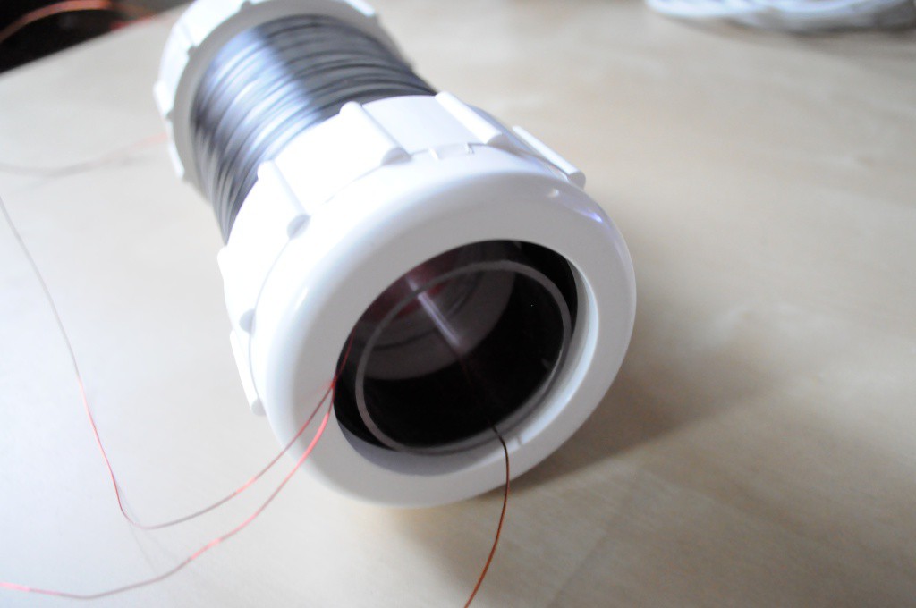
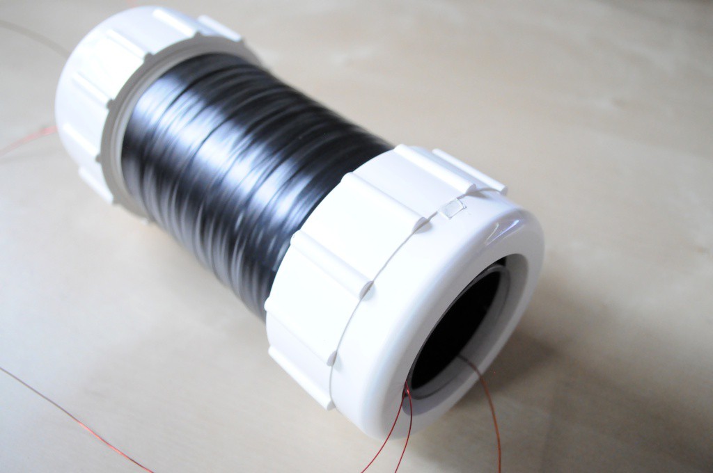
With a minimum field intensity of 100 Gauss and a desired power supply voltage of 12V and ideally somewhere in the range of 2 amps, the constraints were so specific that the prepolarizing coil nearly designed itself. The coil could only have a diameter slightly larger than the sensor coil, so I set off to find a coil form with a diameter of about 2.5 inches. After roaming the plumbing aisle of Home Depot, I stumbled across a beautiful coupler (above) with a ~2.5 inch inner diameter, about 10cm of length for the prepolarizing coil windings, and some wonderful screwable caps with rubber gaskets that allow the sensor coil to be both firmly held in place, and easily disassembled. Great! David popped this on the lathe to smooth out/remove some nubs and markings on the outter surface, then it was time to head on down to coil winding town.
This coil has three layers of 22 AWG wire, at about 128 winds each. This is about 10% less than the theoretical density per layer for this coil form (about 145), but I've found in practice that small kinks in the wire tend to lower the density yield a small amount. I think professional coil winders likely include a jig to straighten the tiny kinks out of magnet wire coming from the spool, but I don't suspect that it'll be an issue here.
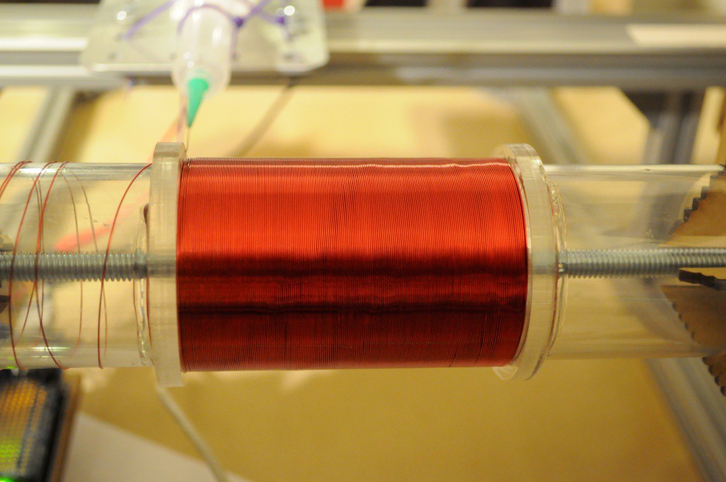
While we were at it, we put together a coil form for a second sensor coil, that perfectly fits inside the polarizing coil. Using the lessons I learned from the first sensor coil, I used wider 1/4 inch acrylic to make the ends for this coil form, and paid very close attention to the distance (exactly 81mm) between the two ends at all points around the circumference. I hadn't appreciated that this would be an issue with the first coil, and the end plates are unfortunately a tiny bit uneven, which makes the tricky bit of stacking one layer atop another extra tricky. At 81mm, this coil form is also about 25% longer than the original, and uses 740 winds of 26 AWG magnet wire, at with 4 layers at 185 turns each.
With these two coils complete, I think we're starting to get very close to having a proton precession magnetometer, and observing the first PPM signal. I'm hoping to connect a relay to the prepolarizing coil, adding a bit of code to the firmware to pulse this, and see if we can't observe our first signals from the subatomic world!
A quick update, with background data recorded from the sensor coil!
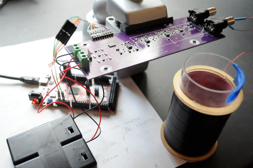
I had the chance to write some firmware to test out the amplifier board this weekend. The amplifier board consists of an AD7680 16-bit 100ksps ADC with an SPI interface, with a 1-10KHz bandpass filter. There's also an AD5160 digital potentiometer to adjust the gain on the final amplifier stage, also using an SPI interface.
I'm still new to the Raspberry Pi, so I put together a quick AD7680 driver for the Chipkit MAX32, which contains a PIC32 processor and about 128K of RAM, or enough to hold about half a second of data at 100ksps. The chipkit reads in this data, then very slowly streams it down the serial port to an Octave script that plots both the time-domain and frequency-domain signals. Because the polarizing electromagnet isn't complete, this first test is just to observe the ambient background radio noise, and verify the amplifier is functioning correctly.

The time-domain plot (above) shows plenty of activity.

And plotting this to the frequency domain (above) shows peaks very closely matching the characteristics of the background noise that Bradley Worley observed with the PyPPM, which he speculated are largely harmonics of the 60Hz line noise, and other electrical noise emitted by nearby devices. This is a great news, and likely means that the amplifier is working as expected! A sharp rolloff is visible at approximately 1 KHz, and signal amplitude decreases quite a bit approaching 10 KHz, also suggesting that the 1-10 KHz bandpass filter is performing well. One issue did come up -- changing the AD5160 digipot doesn't appear to be changing the gain, which likely means that there may be a small soldering issue, or an issue with the driver. Thankfully the default AD5160 resistance was ideal for this test, and occupies nearly half the full-scale range -- so while it's important to have the variable gain working, this small issue wasn't critical in verifying the functionality of the amplifier.
Onward to constructing the polarizing coil, and attempting to observe the first proton precession signal!
A quick update, with the first pass at a proton precession amplifier!
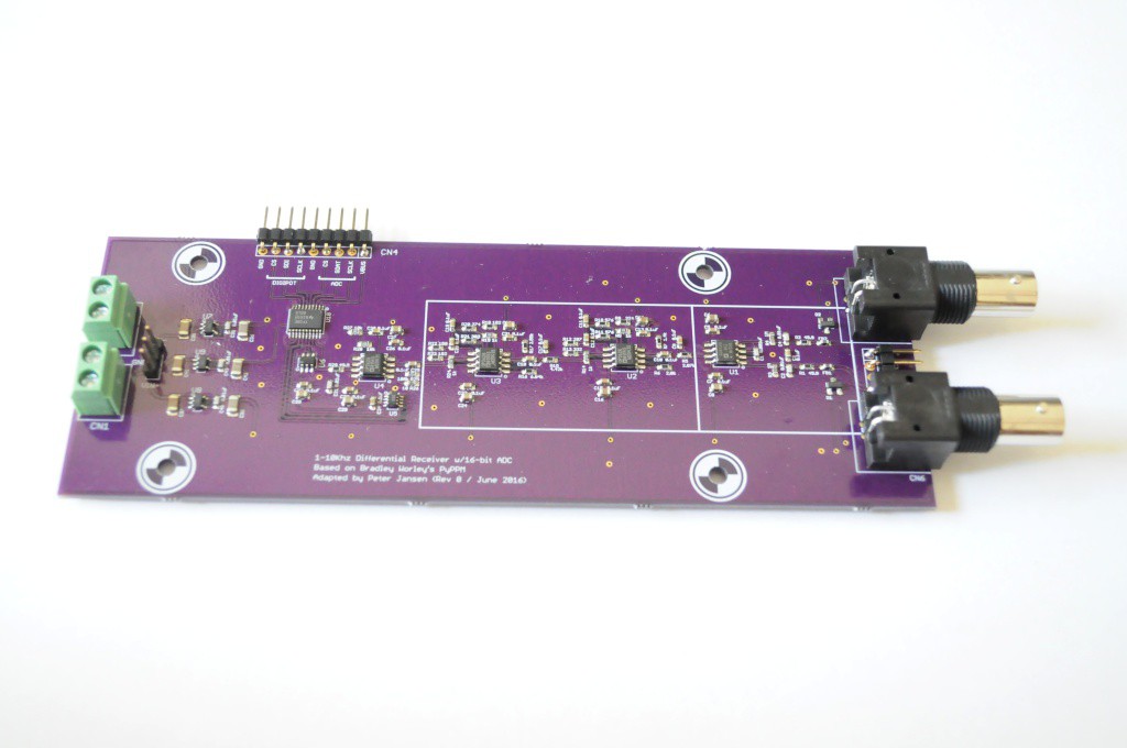
When I'd placed this project on the backburner last year, it was after hitting two technical challenges that I didn't have good solutions for:
This second bit is addressed by the amplifier board, described in this post.
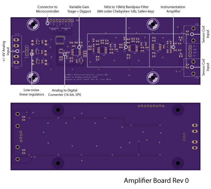
I'd realized that most of my issues in coming up with a design for the amplifier / analog-to-digital converter were over-estimating the specifications for the board -- too high a sample frequency, resolution, and so forth, and that for a first-pass proof of concept, something with more modest specifications would likely meet with success. Thankfully, the requirements of this design are very similar to an Earth's field Proton Precession Magnetometer, which has a small but non-zero community of open-source builders. Bradley Worley, a graduate student in nuclear magnetic resonance, put together a very well documented and iterated proton precession magnetometer about two years ago, after heavily researching what other's had done -- and his work is a great resource, and the most recent build that I've found.

The design I've put together is heavily based on Bradley's design, and uses the same ultra-low noise instrumentation amplifier, low-noise filter opamps, and 16-bit SPI ADC. I'm still a novice at many things analog, including low-noise design, and took the opportunity to pored over the Analog Devices application notes to understand the design choices that were made, and where they might be improved. I made a few modifications to the original design:
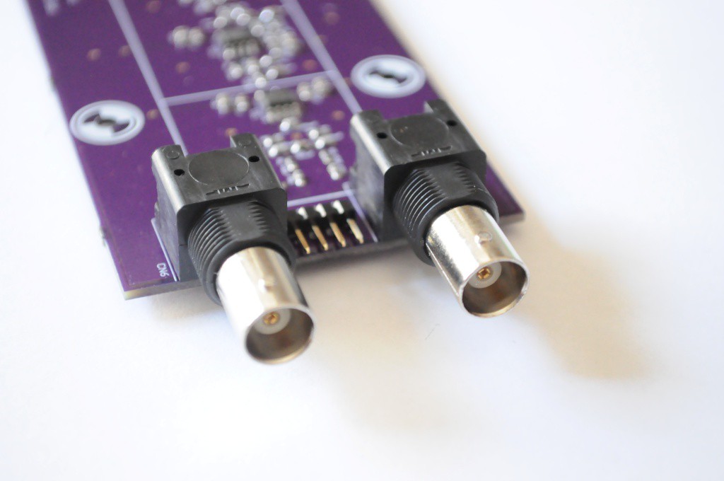
The input to the instrumentation amplifier is differential, allowing for a humbucker coil to be used, as Bradley spec'd for the PyPPM, and the folks who wrote Signals from the Subatomic World used.
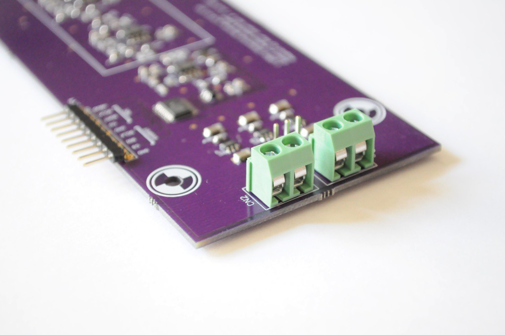
The amplifiers require dual supplies, which are regulated to +/-5V. I think two 9V batteries should work famously -- the draw is very low.
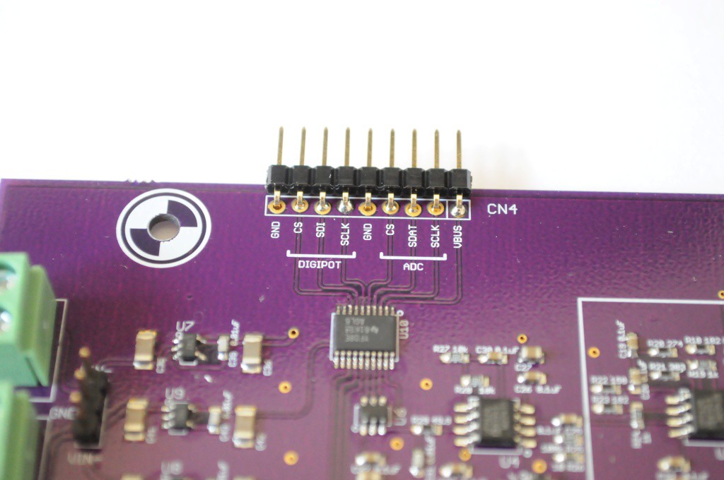
And the user interface connection, with separate SPI pins for both the digipot and the ADC. Here I've opted to break out each SPI interface individually rather than share the clock and data lines as the digipot will likely rarely be changed, but is part of the final gain stage -- so I wanted to avoid having a trace carrying the ~2MHz SPI clock for the ADC nearby, potentially introducing noise.
Next steps
The...
Read more »With the recent success of the OpenCT2, I'm back thinking about the coded aperture MRI again. David was also in Antarctica for a while for his radio astronomy graduate work, but he's been back and we've been chatting about MRI things lately.
The two issues: Coil Winding, and a USB ADC
When the project went on the backburner, I'd hit two stumbling blocks that seemed like good solutions would have to present themselves for before things could progress:
Coil Winding Machine
Just like a prerequisite for becoming a jedi is building your own lightsaber, it seems like a prerequisite for being interested in radio is building your own coil winding machine. Radio coil winding seems like a somewhat lost art (I'm sure if this was a century ago, I'd know a dozen folks who were expert coil winders), but youtube has no shortage of videos of folks who have put together their own machines. It seems that one can also purchase manual coil winders fairly easily, but they tend to look ancient, and like one could come up with an automated design in a few evenings of work.
Being somewhat at the mercy of inspiration, a seemingly simple design suddenly came to me, and after a quick trip to the hardware store for some threaded rod, and by the end of the evening I had cobbled together some leftover Makerslide and Misumi aluminum extrusion into this:
The above half-complete winder allowed was just enough to wind a single-layer coil hundreds of times faster than I'd done it by hand (and nearly perfectly), convincing me that I was onto something.
After another evening slaving over a warm laser cutter, the coil winder emerged:
The different components, drawn from leftover pieces of projects, are the following:
Rotational/Winding Stage (right side):
Linear Stage (middle):
Spool Holder (left):
Control:
The dimensions of the long aluminum extrusion pieces are about 50cm, and the short ones holding each component are about 10-12cm high. The aluminum extrusion makes it easy to resize for larger/small coils, and to move in the tip of the liner stage very close to the coil form during setup.
Winding Coils
Following Bradley Worley's great proton procession magnetometer (PyPPM) project, I decided a good place to start would be replicating his (or a similar) proton procession magnetometer, then experimenting with it under different non-uniform field conditions to see how viable the coded field technique may be. About 10 years ago Stefan and Richard Hollos published a book called Signals from the Subatomic World...
Read more »This is a continuation of a previous project that was placed on the back-burner when I encountered a few roadblocks.
The previous build logs cover the concept, a MATLAB simulator, and measuring magnetic fields in a volume: https://hackaday.io/project/5030-low-field-mri
Create an account to leave a comment. Already have an account? Log In.
Posting several comments , first one on resources
A resource to look at http://www.opensourceimaging.org Particularly gr MRI open source software using GNU radio ( Software defined radio).
GNU radio itself could solve a lot of your issues , it is frequency agnostic and can drive audio frequency hardware as well as RF. Can filter ,process , analyze and store your incoming signal data. Has windows and Linux versions.
Quite impressive package with very user friendly GUI
Your initial runs could use a simple decent audio card
There is an excellent , highly capable broadband commercial SDR hardware interface ,DC to 6GHZ.
This is a really cool project.
Good to see the progress so far. Doing earths field MRI, you wind up operating well inside the audio frequency band, hence you got some options with your electronics (the simplest being using the audio in capabilities of your computer). Ive also used the Teensy board in the past, as it is arduino compatible, yet fast enough to manage an audio-stream, SD card interfaces and more.
Also, something might be learned from the folks at Magritek as they have a similar product (http://www.magritek.com/products/terranova/), which also uses the earths magnetic field for imaging.
Good luck, and I am looking forward to the next post.
I'm also really looking forward to this taking shape. I read through the terranova lit and saw the 90min bell pepper MRI. I suspect that being water vs air it is a simpler problem than water vs fat for example. It would be a really good benchmark to reach. When I looked up low field MRI some years ago it was mostly being done with exotic detection methods, I'm really hopeful for pre-polarisation being enough of an edge to make it work at a hacker level.
Thanks, both! And sorry to be slow -- it's been a bit of a busy week. The TerraNova looks like a great instrument, and I'd love to try one out. The main issues I think are the cost (I think it's close to 20k?), and issues with field uniformity. I think I recall reading a discussion board where some folks were having difficulty getting it working to include in their undergraduate courseowrk, due to the field inhomogeneities introduced by having it inside the building. I suspect this is why in the brochures they mention that it can be run outside, likely on a battery source. I think these two issues (cost, and inhomogeneity) are the major barriers to enabling amateur magnetic resonance imaging, so I'm eager to see if the coded-aperture technique can help out with this. I'd love to see this help bring down the cost of proper medical imaging systems, too, by allowing them to use inexpensive electromagnets, but my sense of things is that if the environment has any kind of changing fields in it, that you'd need to come up with a way of very quickly and frequently characterizing the field for it to become practical.
TerraNova: One of the very encouraging things about the TerraNova is that it looks to be using a field intensity of only 100-200 Gauss for it's polarizing electromagnet, which is right where the electromagnet for this project is, so hopefully it should be able to produce sufficient signal for imaging on realistic timescales.
You're also definitely correct -- water vs air (or, anything with free protons vs air) is a simpler problem, since it's essentially signal at a given frequency versus the the absence of that signal. Water vs fat vs other materials is usually measured by characterizing the decay time of the signal in a given voxel, which is a small amount more complicated in a normal system, but likely a bit more complicated here.
Become a member to follow this project and never miss any updates
 peter jansen
 Bradley Worley
 Ted Yapo
Fascinating!
I know Dr. Damadian, patent holder for the MRI concept and founder/owner of Fonar.
Yes, he holds the patent and every manufacturer of MRI pays Dr. Damadian a royalty.
His original prototype is in the Smithsonian museum in Washington, DC.
He's a FASCINATING man and I believe if properly approached would be delighted to assist I this project (think of the "mad scientist" who really DOES look like Boris Karloff as the "mad scientist".
I've spent many millions with his company as I purchased the first production stand up MRI machines from him.
Check out Fonar.com and my company washingtonopenmri.com for more information.
Go directly to the source and I believe Dr. Damadian would welcome your questions and be a supporter!