ThunderSqueak
-
Notes 1: Random Things that Might or Might Not be Useful - Brainstorm
07/11/2016 at 11:40 • 0 commentsThis is a log of random thoughts that will be updated occasionally with ideas. I have always believed that no idea is useless, it just might not be right for the situation at that time or place. Some of what is written here will be useless, some crazy, some brilliant, and some completely idiotic. But it is more fun if it is all written down so people can see the process by which a project comes to fruition. Just remember... it is ALWAYS a work in progress of partial thoughts and unrealized realities.
===========
I was considering the prospect of recharging, and had this thought. What if instead of a central base station at a central location we teach PAL to seek out designated outlets around the house and plug itself into these outlets. They could be marked, or a different color, or some other thing to set them apart as "safe food". This would require charging circuitry to be on board of course. I wonder if I should see if PAL can figure this one out by itself. Perhaps give it the instinct of "ingest" much like any animal knows to put food in its mouth to eat. PAL will know it has a charging cable (mouth) but not know what to do with it until it maps this information itself. Could be fun... or frustrating XD
I was also thinking about the motivation system. Perhaps in order to keep PAL interested in travel, we include a quota of data somewhere. I can call this instinct "Curiosity". The more curiosity that PAL fulfills learning new things the happier PAL gets. How does this happiness work? Well, it is basically just a number on a sliding scale, which is compared to other numbers on different emotional scales. Through the use of some simple algebra we can determine the primary and secondary moods. These moods will help dictate responses in the system. Finding ways to create a meaningful balance between emotion and functionality is like walking a tightrope. Humans have been doing it since the dawn of human existence... and even we still screw it up and get our wires crossed :P
-
Quick idea - One method of body hinging.
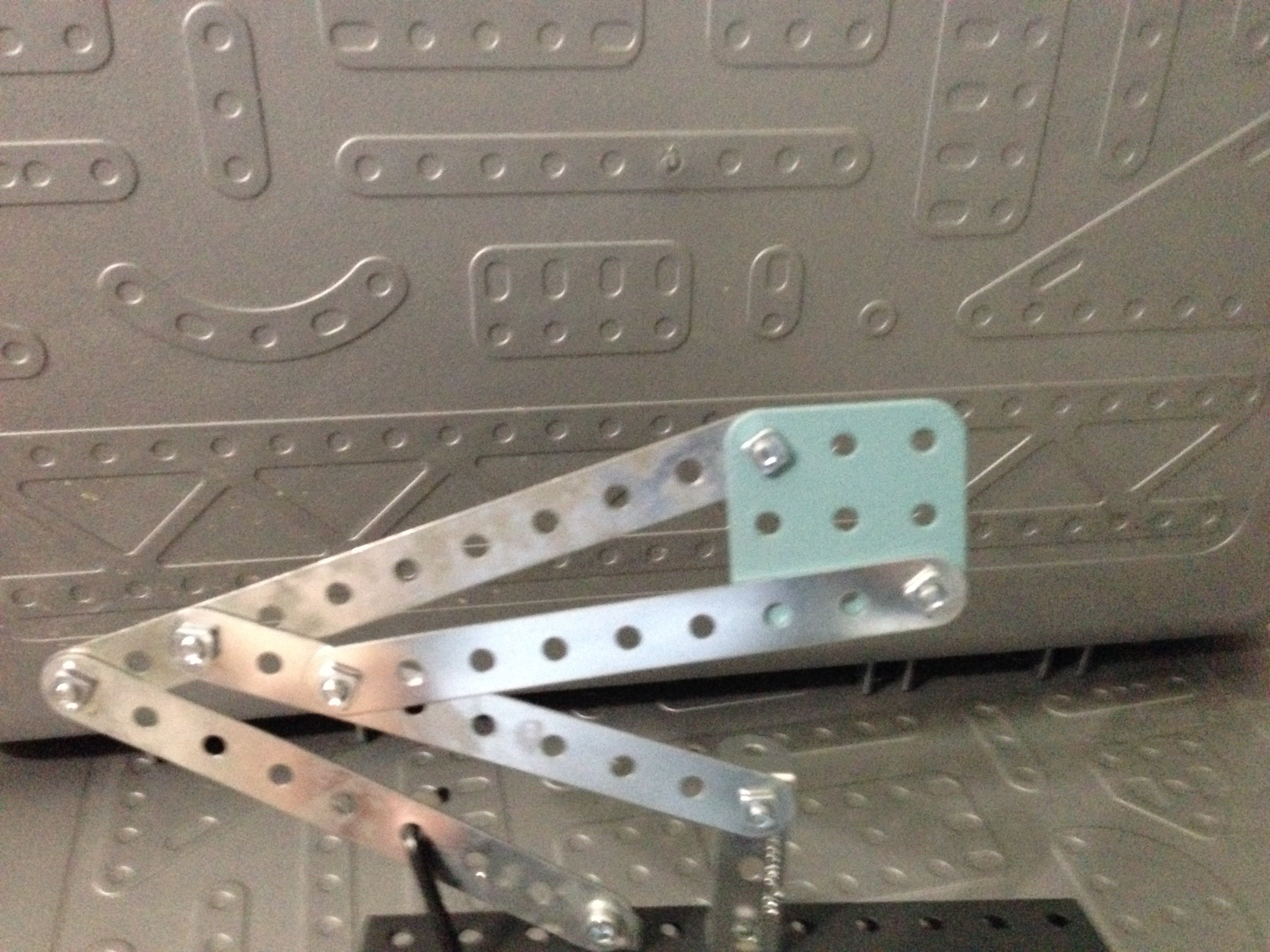
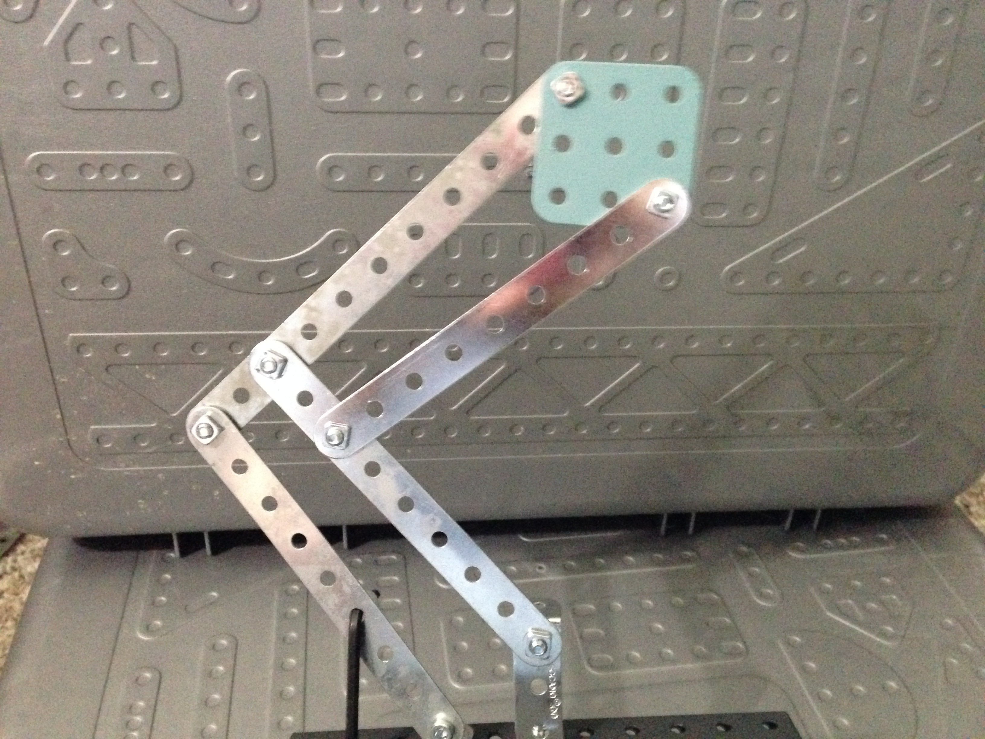
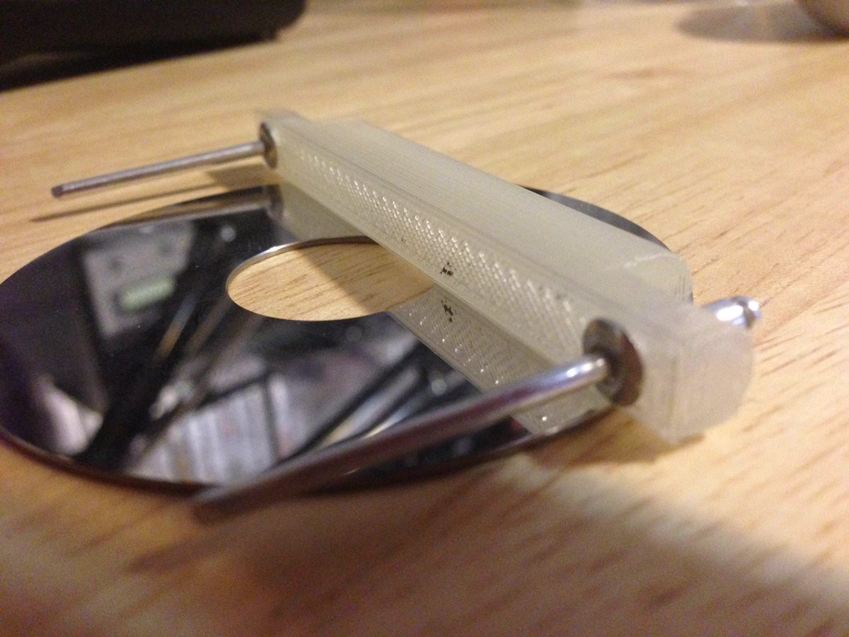
07/10/2016 at 21:13 • 0 commentsUpon waking up this morning, this idea was in my head. A way to have the body lift, keep the head reasonably level, and be controlled by one single actuator. A quick test, shown below, is the basic premise of the idea. It will require some of force, but considering the materials I am using and the overall weight, should be doable.
In the test, an Allen wrench is acting as the actuator and being pushed up or pulled down through a hole in the platform. By placing the bottom hinges at different levels we get a relatively straight upward lift as well as allow the body to lower and enter "Race Car Mode". This motion is extremely fluid and nothing binds up at the start or finish.
![]()
![]()
In the full design I am working out how to best use this concept to achieve a stable structure while allowing the "chest" area to have a compartment for additional places to mount hardware. Other concerns include how to mount the ball bearings, how to give some strain relief to the motor used in the actuator, and of course there are some aesthetic concerns :)
Cheers!
-
The body Lift, let PAL stand up or Lower for high speed maneuvers.
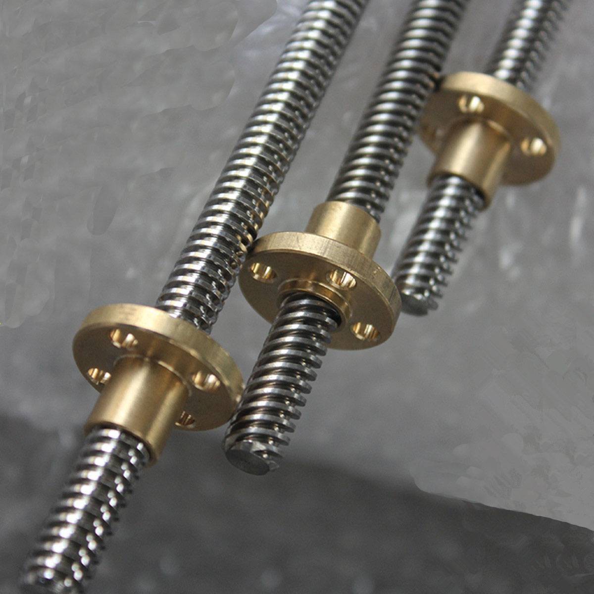
07/10/2016 at 00:56 • 2 commentsI was thinking about the cost of linear actuators and how to accomplish the raise and lower action for PAL's body. There is a space between the end of the motors that can be used to let a threaded rod push and pull, and also swing a bit.... why not use that?
A quick search on amazon revealed this,
![]()
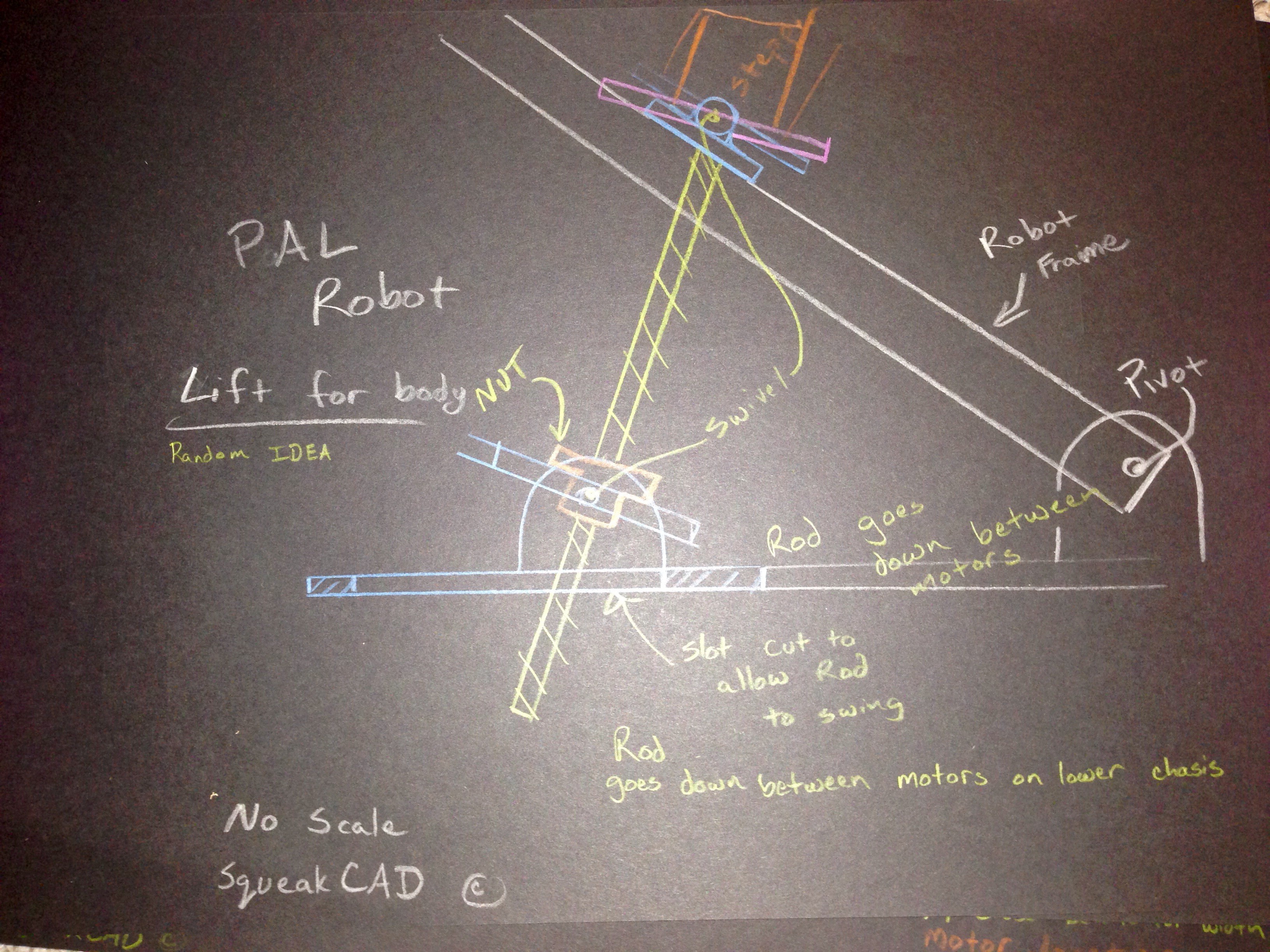
Since I have about 6 inches of clearance inside PAL, I can use a rod about that long. Next up, I did a quick 5 minute sketch to work out the mechanics. A set of pivots will be needed. But if placed correctly, PAL should be able to raise and lower to an almost completely flat state for faster travel and greater stability when needed. I will call this "Race Car Mode".
Nothing is to scale, as this is just a rough idea of what is happening.
![]()
Cheers!
-
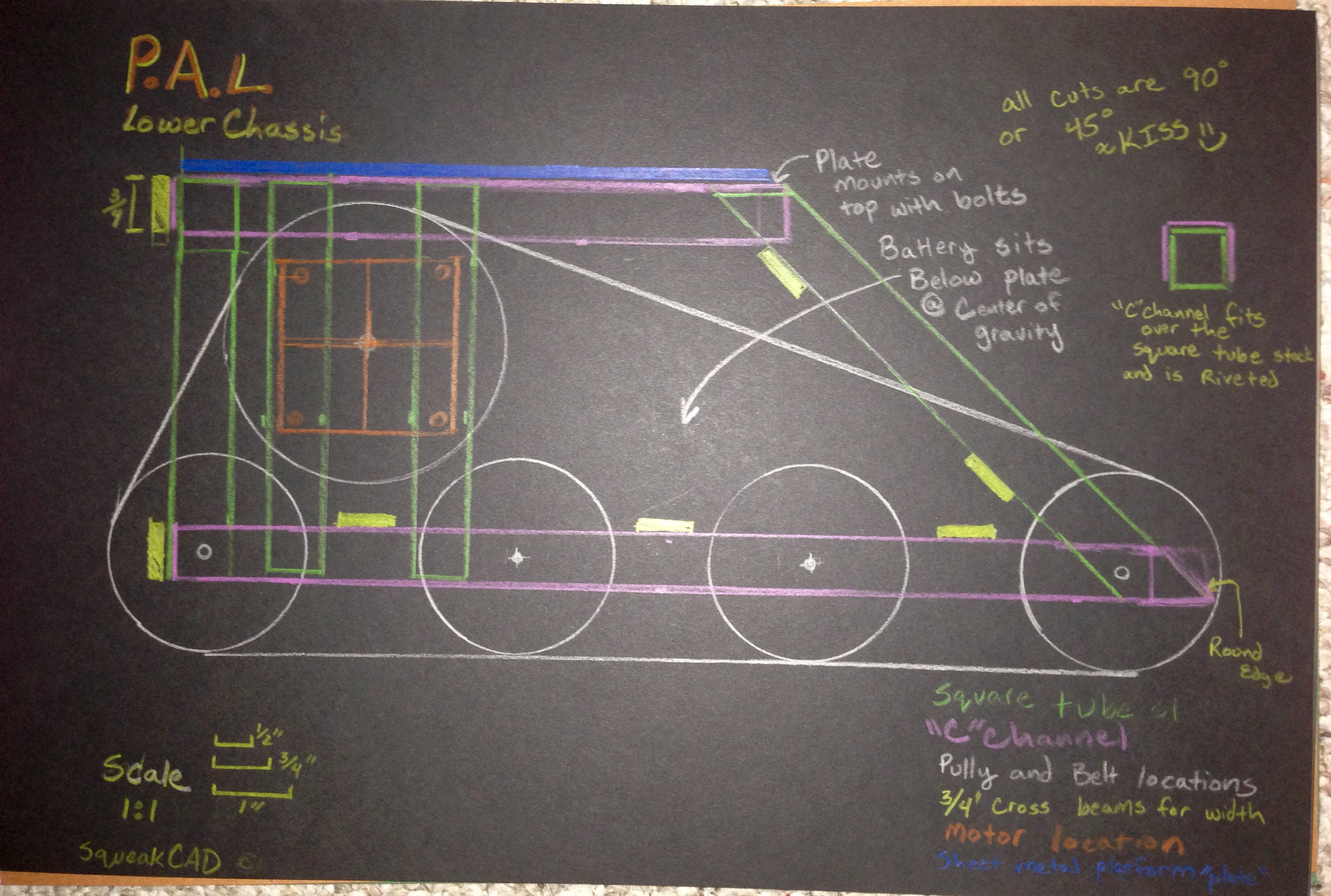
Lower Chassis - A quick sketch
07/09/2016 at 22:40 • 2 comments![]()
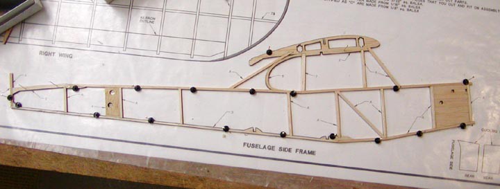
In an effort to keep things simple, a thought occurred. As a kid, I used to build model airplanes right on the plans, with some waxed paper covering them to keep the glue from sticking and push pins to keep things in place. Obviously I cannot use push pins and glue, but what I can do is draw it 1:1 scale and just get it to feel right, then using a saw cut the pieces.
In the construction of the lower frame, two identical sides are made and then connected with cross members to set the width. The platform should be a sheet of sturdy metal or wood, depending on what I can find when the time comes.
The clearance height is sort of low, but that does not matter in this case as PAL is going to be indoors.
The construction will use "C" channel, square tube stock, and flat aluminum stock all in the 3/4" size as that is what my chop saw will cut. All angles are to be either 45 degree or 90 degree cuts with most of the structure riveted together. The "C" channel wraps tightly around the square tube material, which makes a very tight mechanical fit before the rivet holes are drilled and rivets put into place.
The battery will be mounted near the center of gravity, and a custom platform will be made when I have selected the power source. Due to the motors I have access too, I am planning on making it a 24V/5V system.
![]()
Sometimes it is fun to just sit down with some paper and colored pencils :) One detail that is left off of the diagram is the fact that the lower cross members are sitting on the open side of the C channel, I plan on simply putting some short pieces of the tube stock in there to allow me to rivet those in place.
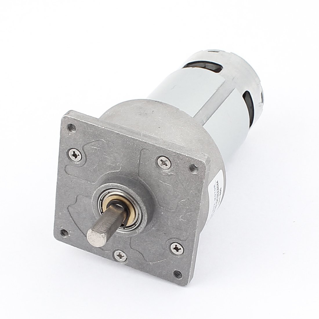
This is the motor I have access too and depending how things work, should be using.
![]()
I will upload final part numbers after things are put into place and functional.
Cheers!
-
Thinking about the track and how to build it on the cheap
07/09/2016 at 09:39 • 0 commentsI want to build the track system completely from scratch in order to keep cost down. The chain I have on hand is a 25H chain, pretty small.
After thinking about it a bit, I decided it might be best to run two chains separated by the part you see below. I will only place this on the solid links, not the ones between holding those solid links together. After I do this, I can 3D print a nice "sprocket" that fits the track well.
The part is simple enough that if the plastic does not hold up running around my house on carpet I will just sand cast them out of aluminum.
This was printed on draft mode with 100% infill to make it very solid. The idea is to use rivets to attach it to the chain. The curved bottom will fit into a sprocket while the chains are kept from sliding off by a guide that will also be printed into the sprocket.
![]()
In other news, some but not all of the parts for the audio recognition system arrived today, still waiting for the rest of it before I get that system constructed.
After looking at the bar stock that I have and my old hack saw, I also ordered a small chop saw designed for cutting aluminum at 0-45 degree angles. This should simplify and speed things up tremendously during the chassis/body build.
Tools are never a bad investment :)
-
SSH into a Raspberry Pi using the Mac Address instead of the IP Address
07/07/2016 at 07:12 • 1 commentSo, I decided the best way to interface the pi was to use the tried and tested ssh command. After adding the wireless network to the configurations via the command line. I wanted to do it without installing nmap on every machine. This is how it was done.
On the pi:
Things you will need:
- MAC address of your pi
- Enable the SSH server using raspi-config or some other method
You also need to edit a file and add to the end of it if you are using wifi. A possible command is:
sudo nano /etc/wpa_supplicant/wpa_supplicant.conf
then add
network={
ssid="<name of your network>"
psk="<network password>"
}
After that, if it doesn't connect right away, simply reboot.
On the *nix machine you are connecting from:
I am using a linux machine so rather than having to type in the IP every time I want to connect, and rather than setting up a static IP I chose to write a small script.
Put the following in a text file on the machine you are connecting from, you can name the file whatever you want. I named it robot.sh since it is the brain of my robot :) Be sure to change <username> and <mac address of your pi> to the proper values.
ssh <username>@`for ((i=1; i<=29; i++));do arp -a 192.168.1.$i; done | grep <mac address of your pi> | awk '{print $2}' | sed -e 's/(//' -e 's/)//'`
to make the script executable you can:
sudo chmod +x <filename>
Now, whenever I invoke the robot script, it looks for the pi by mac address, then connects to it via ssh. You still need to enter a password if your pi is properly secured.
Other info:
The pi is running the latest, as of this writing, version of Raspian lite. I did not want to clutter up space with unnecessary software and just install the required development tools.
on a side note, htop is also a useful program to install for monitoring running software on the pi.
Another useful script for monitoring the temperature of the pi is:
#!/bin/bash
cpuTemp0=$(cat /sys/class/thermal/thermal_zone0/temp)
cpuTemp1=$(($cpuTemp0/1000))
cpuTemp2=$(($cpuTemp0/100))
cpuTempM=$(($cpuTemp2 % $cpuTemp1))
echo CPU temp"="$cpuTemp1"."$cpuTempM"'C"
echo GPU $(/opt/vc/bin/vcgencmd measure_temp)
Save it to a text file on the pi and make it executable like before using the chmod command. I had to run the temperature script with sudo to get it to report the GPU temp properly.
These are some of the things I found useful when prepping the pi for use in my robot. Hope others find it useful too!
Cheers!
-
Design choice - mounting the brains.
07/06/2016 at 19:55 • 0 commentsI had a random thought and decided to write it down before it was forgotten.
Since each board is roughly the same size, including the boards that I am making, I think I will create a tray that has "slots" to hold the boards vertical and side by side. By doing this, it is hoped that I can put some vents at the top and allow the heat to rise. The idea is to get away from the effect of having lower boards "roasting" the board above it.
The inspiration for this was a glance at one of my older retro computers across the room. It features an S-100 bus. I will not be implementing such a bus, but method of board mounting just looks right.
![]()
-
Partial Parts order completed, now just to wait :)
07/06/2016 at 02:20 • 0 commentsI ordered some parts today to get some of the subsystems built.
Systems that are ordered are the Motor Controller for the main drive motors. I went with
http://www.robotshop.com/en/sabertooth-dual-2x32a-6v-24v-regenerative-motor-driver.html
2cm - 10cm Infrared Distance SensorDC-DC Power Converter 25WStep-Up / Step-Down Voltage Regulator S7V7F5HC-SR04 Ultrasonic Range Finder2.54mm JST Connector KitFor the speech system I ordered
8 pin socket
18 pin socket
20 pin socket
28 pin socket
2n3904
10k resistors
100k resistors
47k resistors
.1uF capacitor
33pF capacitor
.47uF capacitor
250uF capacitor
Electret microphone
MSGEQ7
I already have the 8 ohm speaker, 2 pin screw terminal blocks, header pins, TTS256, speakjet, and lm386
As soon as the main lower chassis arrives, which should be late this week or early next week I will get that portion assembled and begin work on the robot's body frame and limbs.
I had an odd thought today about the grippers, and was considering using a padded finger tip with a very tiny magnet in it and a hall effect sensor. When the hand is closed the padded fingerip will "feel" the pressure and respond accordingly. If I use a rubberized pad, it will also give the robot some extra grip and mold around the object the robot is picking up. I will think more about this when the time comes.
-
Quick schematic of speech
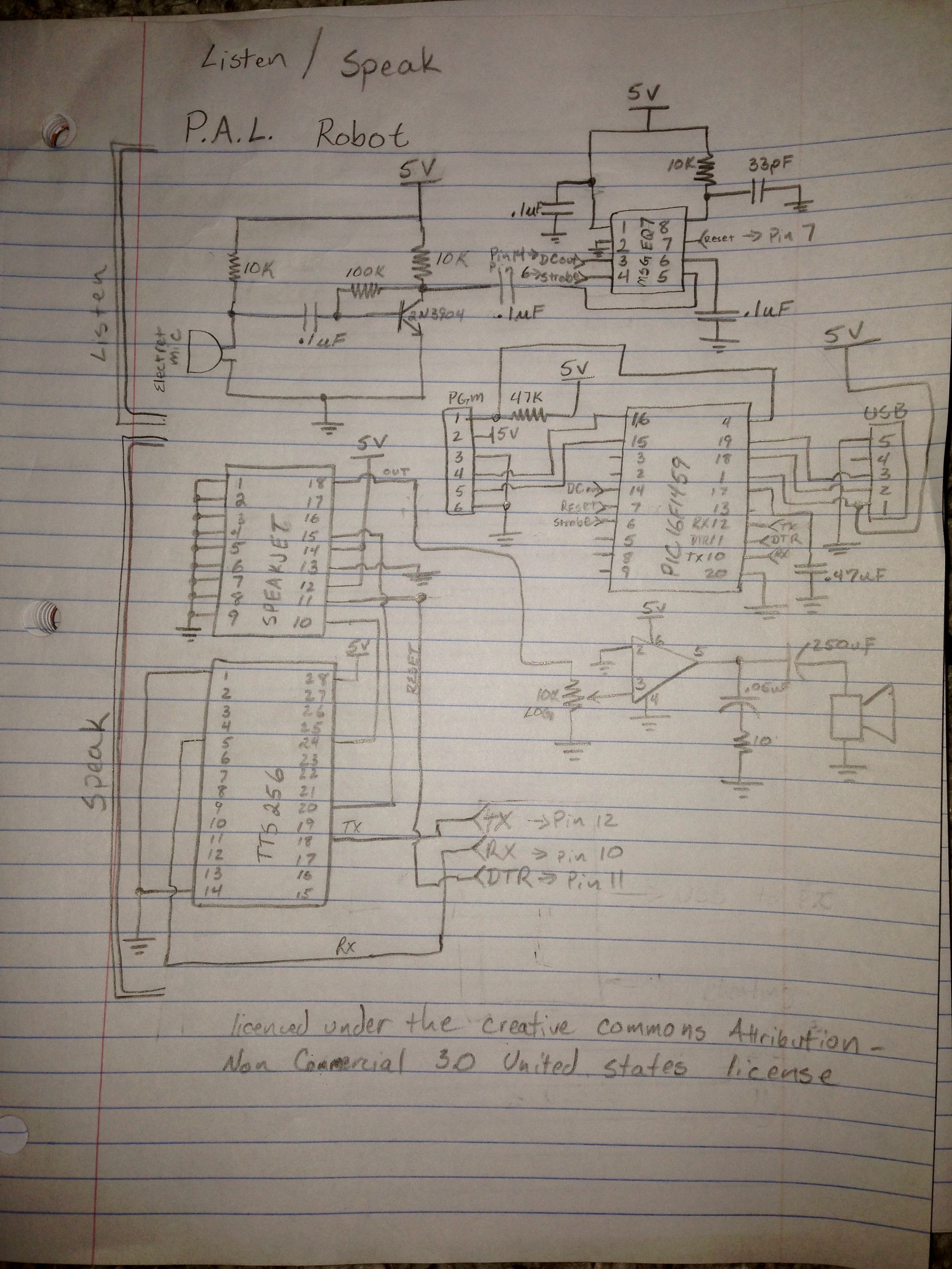
07/05/2016 at 04:24 • 0 commentsuick rough draft of the speech system. The basic operation is controlled by a 48Mhz micro controller which acts as a serial relay to the tts256 IC, much the same way an ftdi chip would. The MSGEQ7 is controlled and interpreted by the pic16F1459.
Since the design is so simplistic, not sure I plan on etching a board for it, and just putting it onto a veroboard with some IC sockets.
Things may change, but lets give this rough back of the napkin schematic a try. :)
![]()
-
Voice/Audio recognition - a strange thought
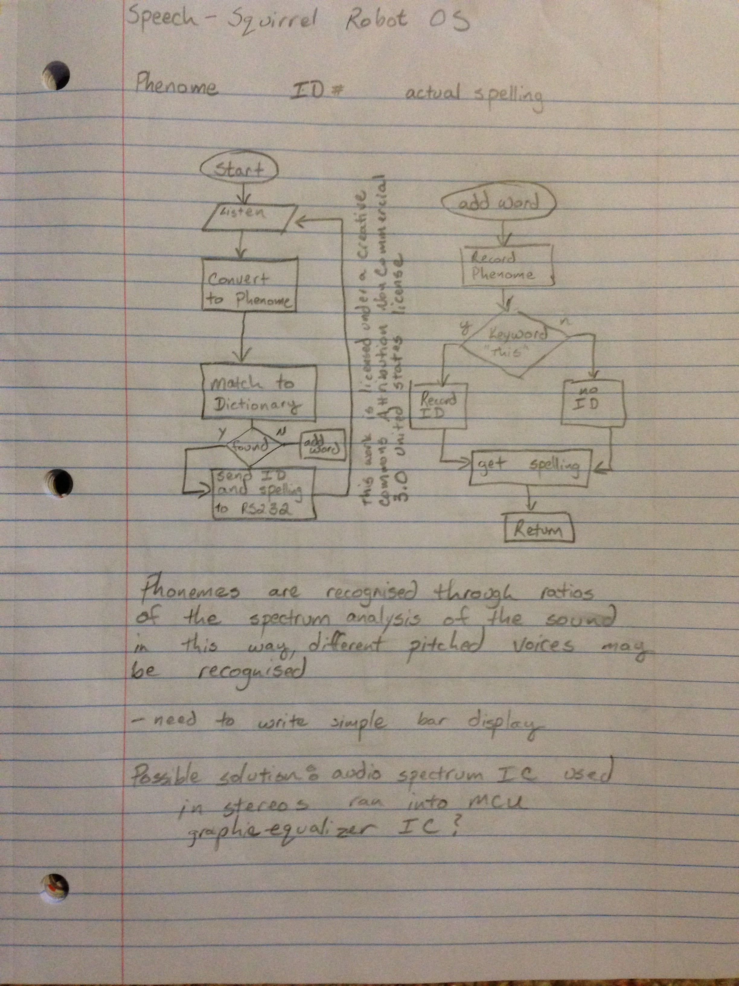
07/02/2016 at 19:20 • 2 commentswas thinking last night before I went to bed about voice recognition. I started keeping a notebook next to the bed years ago and woke up to find this scribbled down.
![]()
The part in this idea that interested me the most upon waking up is the thought of using a graphic equalizer IC to capture phonemes and other sounds. Every sound has its own spectrum signature, including human speech. The next step is to pick up a small graphic equalizer IC such as the MSGEQ7, which is a 7 band equalizer, and give it a try.
The thought is to capture the pattern roughly every 200ms and compare key point ratios to a table of known sounds. By using a ratio algorithm, the thought is that even if there is a change in pitch it should be able to identify certain audio signatures. After identifying these signatures, the micro-controller then shoots off a serial packet to the main board for use.
Initial testing by simply speaking into my spectrum analyzer with different phonemes shows that this idea, at least in general, works. :)
Now to see if those 7 bands are enough to identify different signatures.
I know I could simply run an open source speech to text program on the pi, and it may eventually come to that. I do however, wish to get as much of the lifting off the central control system as possible.
A link to the datasheet of the IC mentioned above. Other chips may work, this was just the first one I found with a quick search.
https://www.sparkfun.com/datasheets/Components/General/MSGEQ7.pdf
For the Microcontroller, I am considering the use of a pic 16F1459.
P.A.L. - Self Programming AI Robot
P.A.L. : Personable Autonomous Learning - Self Programming Robot that learns and grows - Each robot developes a unique personality.