ThunderSqueak
-
GRIP
08/23/2016 at 01:14 • 3 commentsIt has been asked a number of times, "Are you going to add some sort of rubber belt over the tracks?" I have indeed been considering this. One option I have been seriously looking into is simply roughing up the surface of the metal and giving it a coating of a rubbery truck bed liner, Liquid Electrical tape, or one of the other plastic cotes. This sounds much easier than attempting to either rivet or glue cut up tires to each plate in the tracks.
Another option for indoor use could also be some sort of fabric "boot" that covers the entire track. I don't really have to worry about tearing up a hardwood floor at my home, but ya never know... it might be useful?
Time will tell which option I go with...
An example of truck bed liner application for those who are curious.
cheers!
-
Update
08/20/2016 at 10:06 • 0 commentsHello!
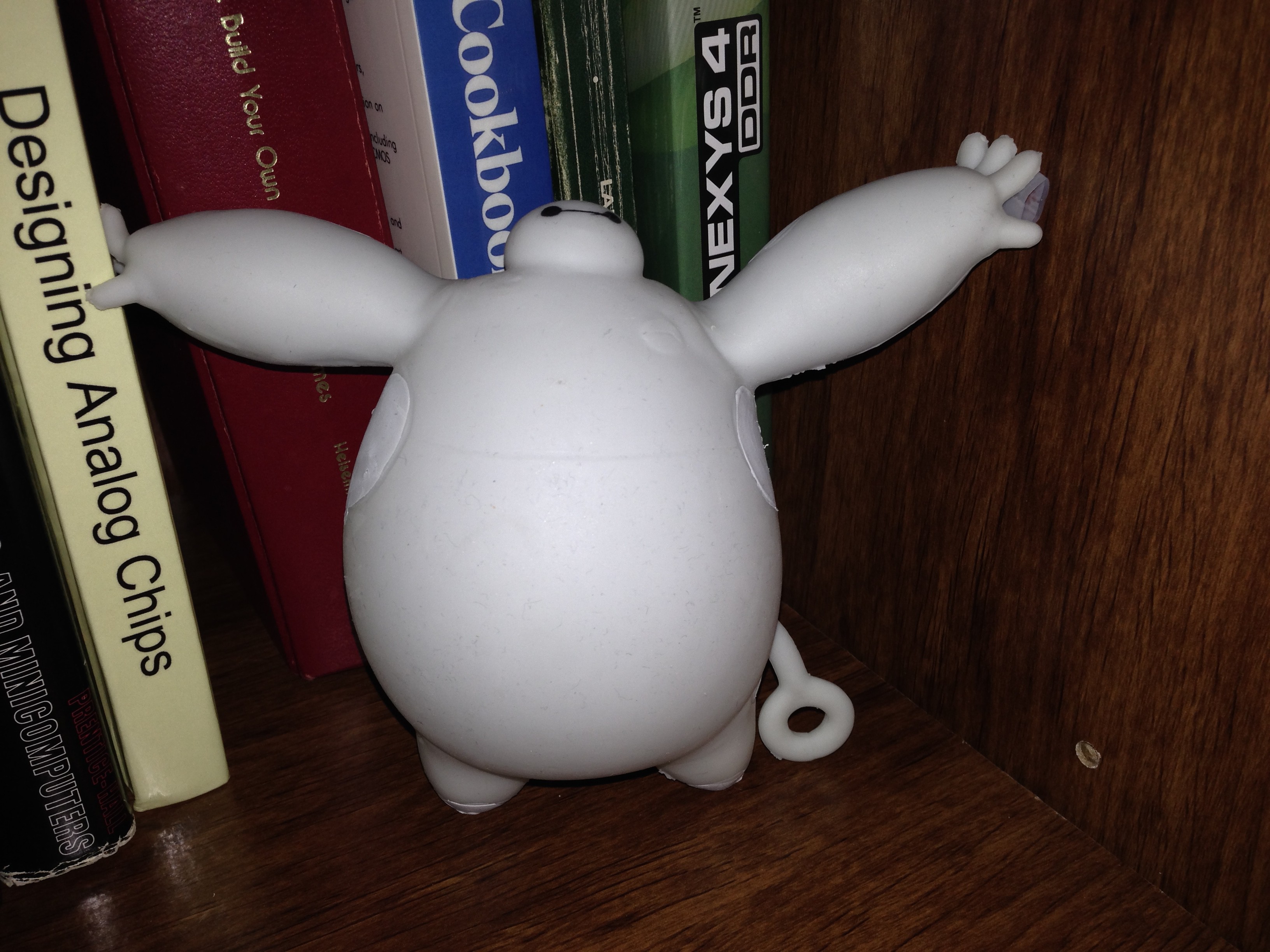
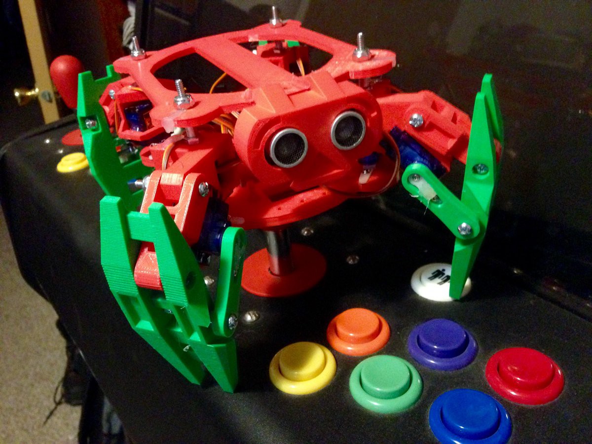
While waiting for parts to be delivered, I have been working on some of the other items in the build. One of these is the Squirrel OS. To help with this process I constructed a small limited robot that has been lovingly dubbed "Turtle". The design is from thingiverse, with a modified body to fit some of PAL's internals. You can find these files here http://www.thingiverse.com/thing:152638
and here http://www.thingiverse.com/thing:772740
The small robot body took a few hours to assemble after it was all printed. Infill is 20%, so the limbs are very light weight.
The brains are a small servo controller from http://electronics.chroma.se/rpisbv3.php (purchased on ebay) and a Raspberry Pi 3B. It does not have the speech module as of yet, this is more to get the base logic working before I transfer it to the much larger robot PAL.
The resulting robot:
![]() Eventually, it may become a pet for PAL :) He looks terrified @.@;;
Eventually, it may become a pet for PAL :) He looks terrified @.@;; I also dug out my old Futaba 6EX FASST radio to test the limits of the track system when it gets assembled. After 10 years of being buried in the closet, it needs a new battery so I will need to order one of those when I get the funds for it. I looked at other systems but the range on FASST radios is hard to beat (about 3 miles). The FHSS systems they offer in a lower price range are geared more towards park fliers and have a much shorter range. I also need to purchase a battery charger as I cannot find my old one. It was lost in a move years ago. Currently I am looking at the Triton EQ http://www.electrifly.com/chargers/gpmm3155.html
That is it for this update, I figured that I would let everyone know that this project is alive and well and one that I am determined to finish :D
Cheers!
-
Hi! I'm P.A.L.!
08/10/2016 at 00:01 • 0 commentsWhile coding last night, the soft chirping sounds of steppers kept me company. With clockwork punctuality, a large fan began whirring loudly in the build chamber. From the comfort of the couch I peeked around my arcade cabinet, hollow eyes peered back with a blank stare.
I took this bit of plastic and wandered over to the bench. After several moments of fitting the small puzzle of fresh parts together there was a spark of imagination. I set this newly formed construct down and picked up the camera. As if it spoke, a mental image formed ....
"Hi! I'm P.A.L. ... Let's explore AI together!. "
![]()
======
Next up, the neck.
-
A pile of components - an update
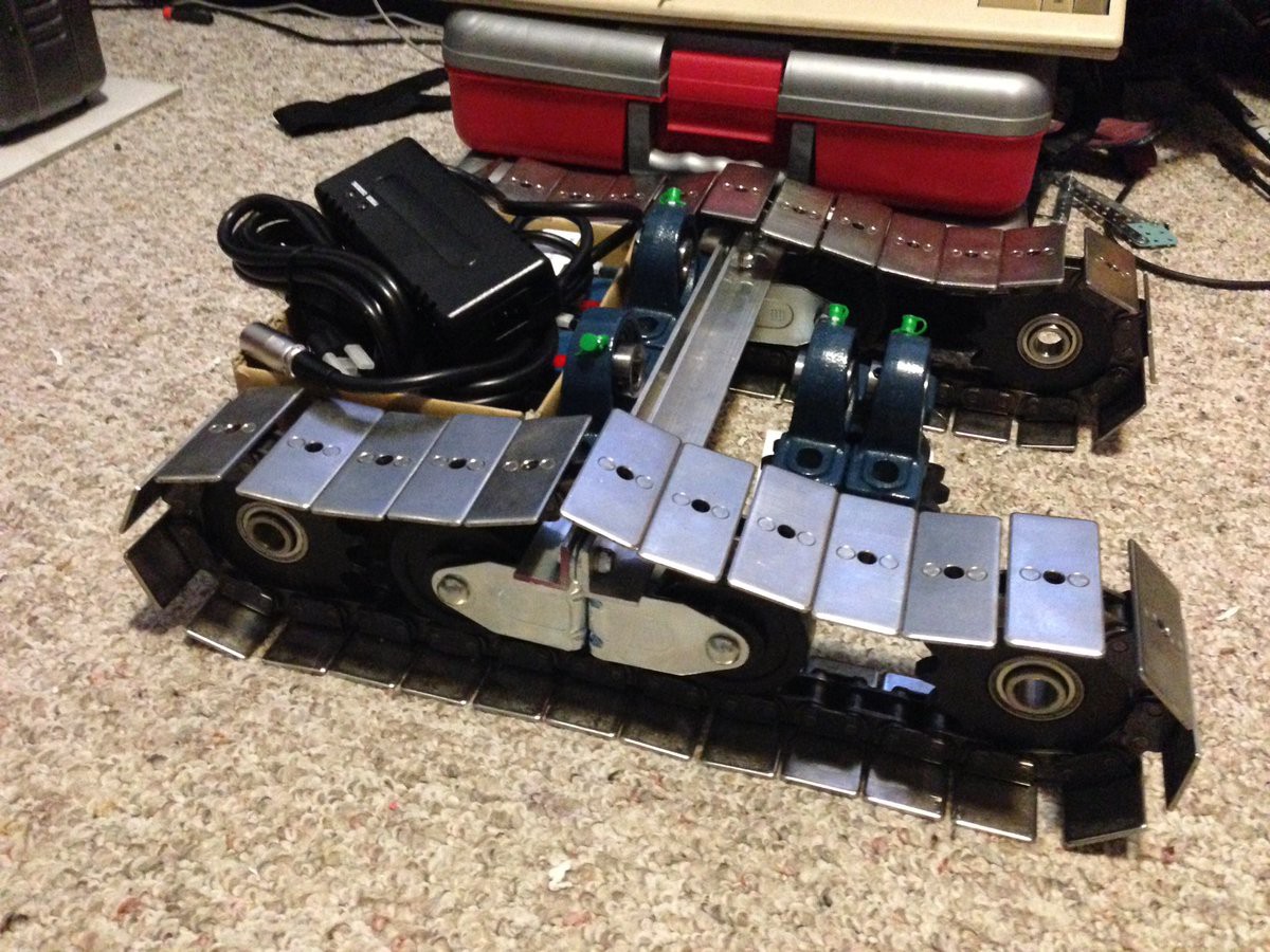
08/07/2016 at 08:00 • 0 commentsWhile I wait for the final components that I had ordered to arrive in the mail, I decided to print out a more "final version" of the 3D models that are going to be used. I have been doing a lot of thinking about how to go about attaching the axle, the idler sprockets, and other components. I have decided that the space between the tracks will be 9 inches and that the main drive sprocket will be driven using a 2:1 gear reduction using appropriate 25h chain and sprockets. Those are still yet to be delivered. I am still waiting on some electronic components to come in before I finish assembling the last few boards that are in the brain. Even though it is just a pile of parts, it is starting to look like a lower chassis as things pile up :)
I am considering using some threaded rod as the idler sprocket axles, as I do not have access to a lathe to make a proper axle. The bearings will be captured between two washers and nuts with some thread locker. These axles will then be secured to the frame with the use of 'U' bolts fed through the frame. I guess time will tell how it holds up as the rod is 5/8", this means that at its core it will be about 1/2".
The large pillow bearings are for use in the main drive for each track. In the box, there are two 12v ps-1290 f2 lead acid cells that will make up the 24v power supply. The black "brick" on top of the box is a 2amp 24v battery charger.
The center bar that you can see in the image is to hold the center wheels on each track. This will go over the base of the chassis and be riveted or bolted in place.
I need to upload a fixed version of the current BRAIN.zip as well. I am printing it for a test fit at a higher resolution as I write this.
And now... A pile of parts that make up some of the lower chassis!
![]()
That's it for today's update.
Cheers!
-
Track layout - Track support structure
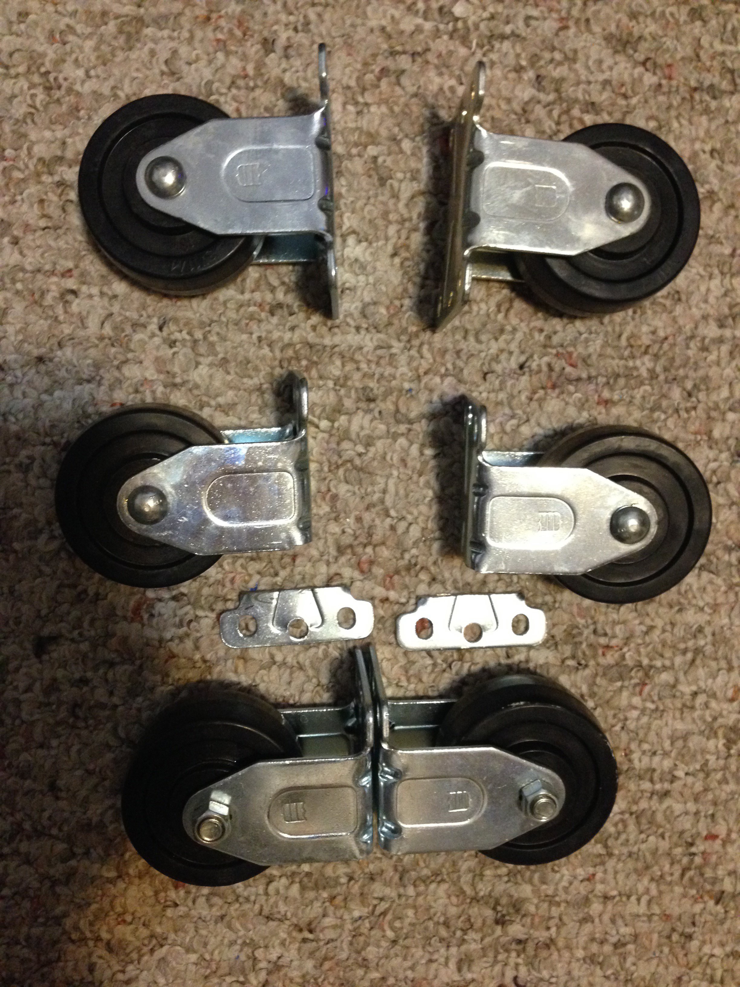
08/02/2016 at 06:47 • 0 commentsWhile I was working today, I suddenly got an idea. Since I changed the track structure, I needed a way to give some reinforcement to the part between the ends. In the previous design, I was to be using heavy duty casters. I might as well put some of them to use. With some minor cuts using a good pair of safety glasses and a dremel... I made these.
![]() By cutting off the one side of each caster, they have enough clearance to allow the parts to roll comfortably. The thought is that in the final design it will end up looking something roughly like this. Please note, I am waiting on sprockets to arrive in the mail, so those parts are substituted just to give an idea of the basic shape.
By cutting off the one side of each caster, they have enough clearance to allow the parts to roll comfortably. The thought is that in the final design it will end up looking something roughly like this. Please note, I am waiting on sprockets to arrive in the mail, so those parts are substituted just to give an idea of the basic shape.![]()
I have also uploaded a current zip file titled "BRAIN". This file contains the current 3D models in 123D and STL format.
Take care!
-
A quick update - lots of pictures
07/28/2016 at 11:03 • 0 commentsI have been meaning to do this update for a while now and since it is 3am, and I am seriously overtired... seems like the perfect time!
The initial concept has given way to some more practical designs choices.
First up, the head.
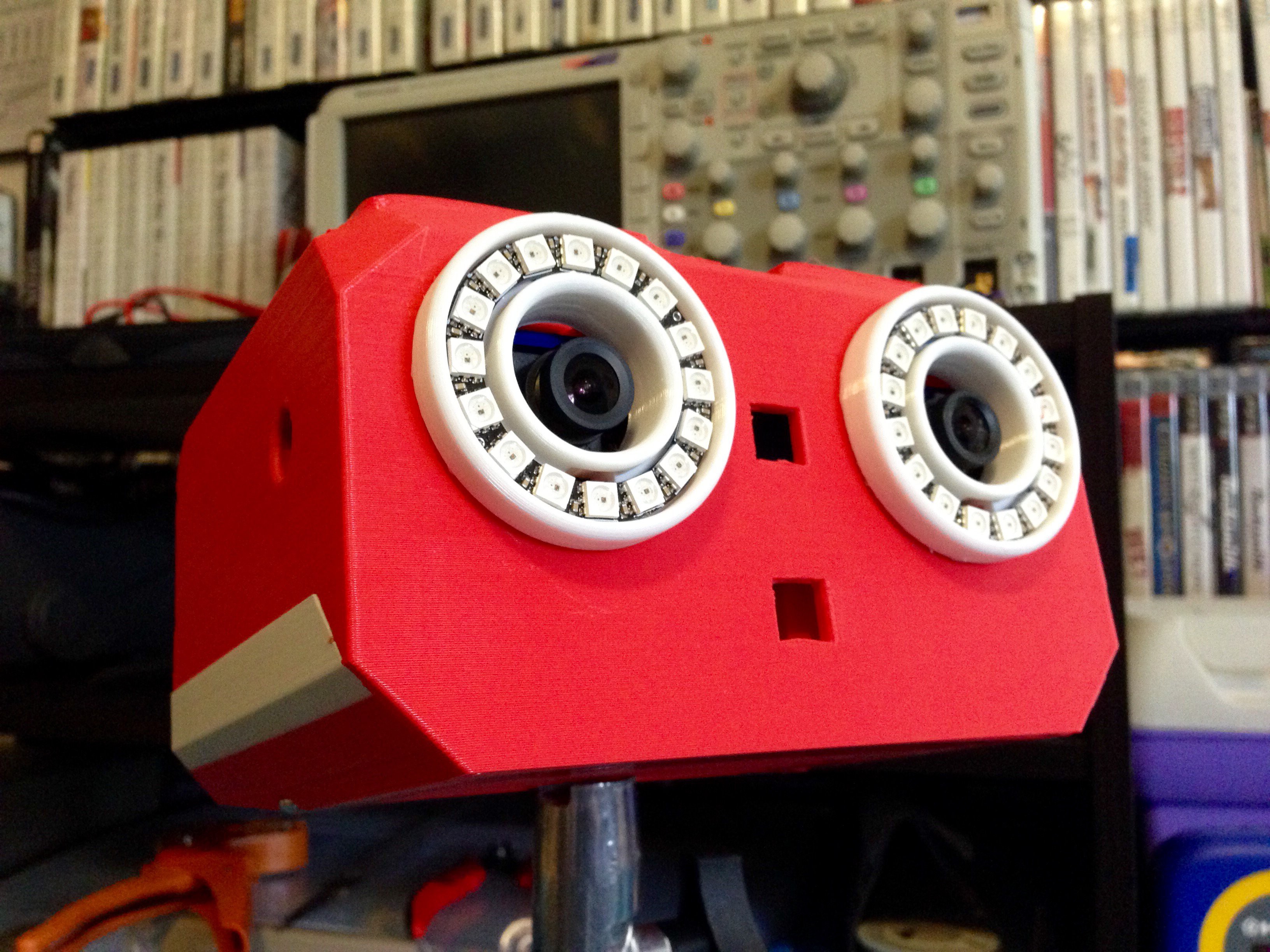
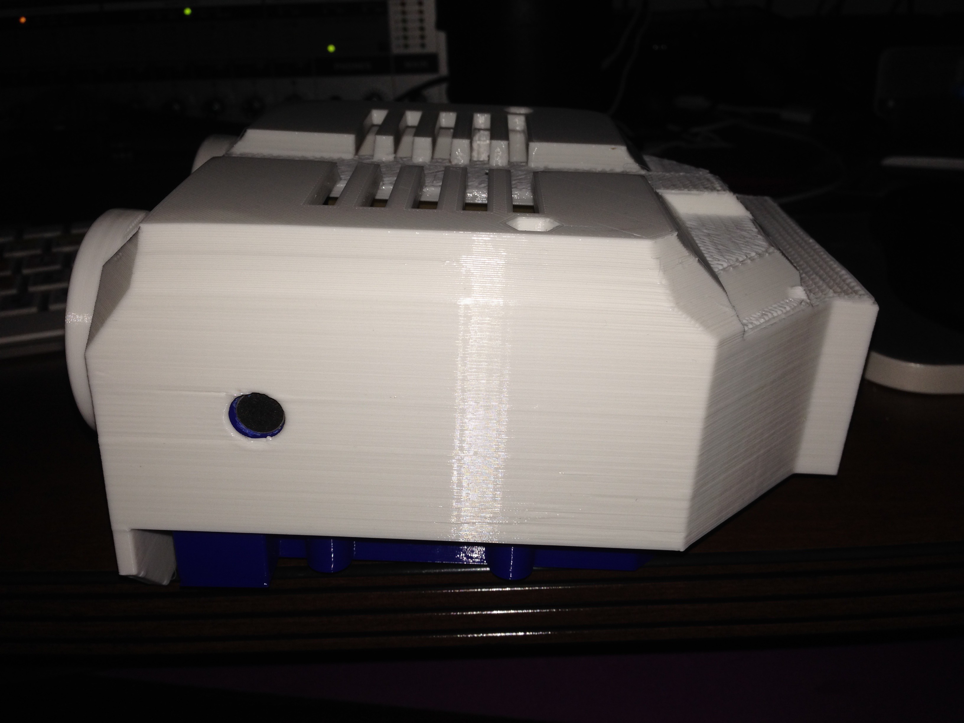
I went with a tray that holds everything, the cameras are locked in place with a top cover that screws into place. I still have to print a retention clip that holds the boards down into the tray, this clip will fit right up behind the eyes between the two screw mounting holes.
![]()
![]()
The eyes have also changed somewhat, gone are the eyelids... at least for now and in their place I am making use of some LED rings. These rings have individually addressable LEDs that can blink, change color, and shine a bright light when PAL needs it. The two holes between the eyes are for a speaker and another visual effect led that will flash when PAL speaks. On the side of the head you see a set of stereo microphones. The whole thing bolts together by feeding through to the top of the head where a couple nuts hold it all in place. This design also leaves me room to hook up the "neck" system later.
![]() That is one blank stare XD
That is one blank stare XD![]()
![]()
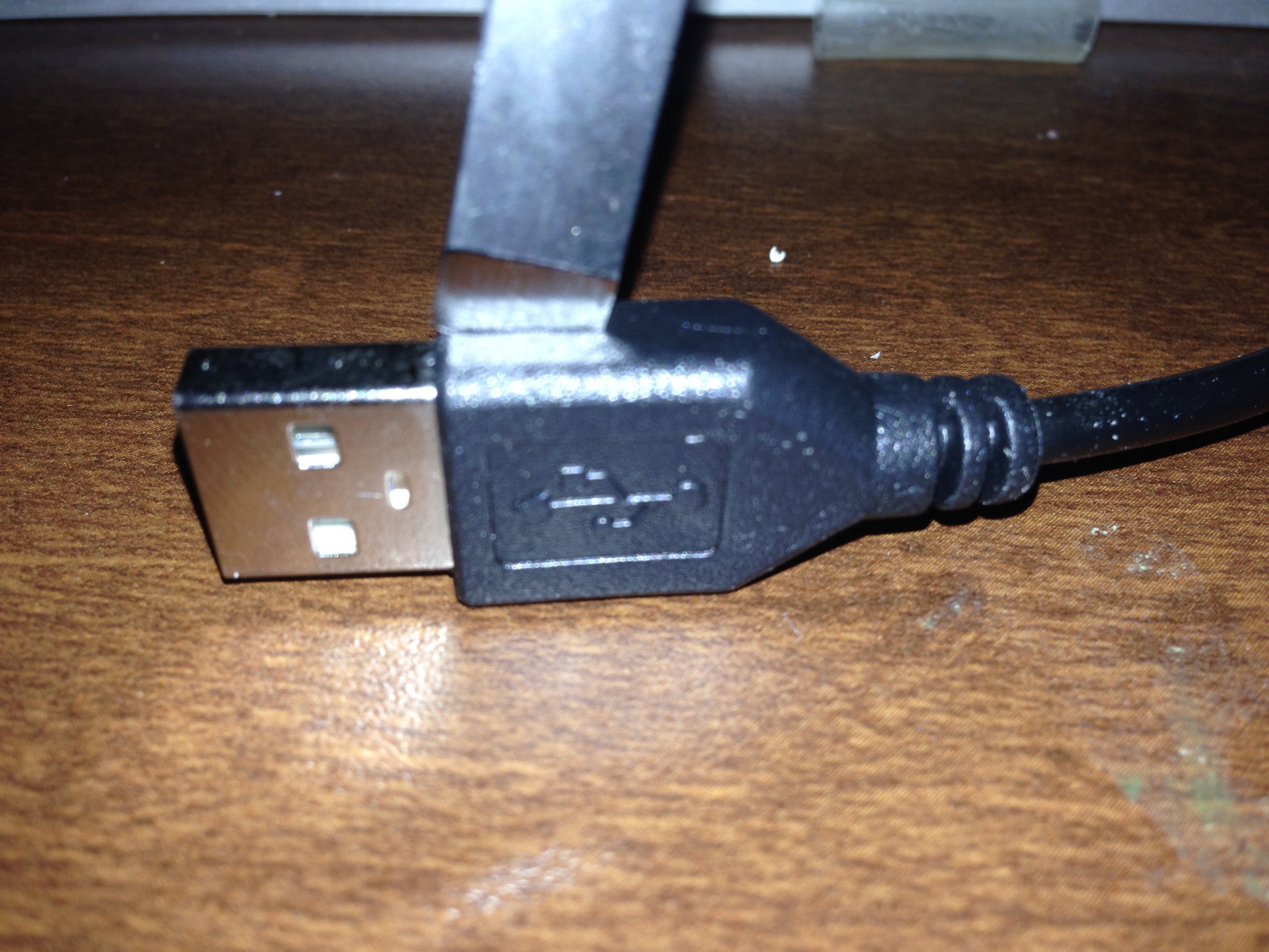
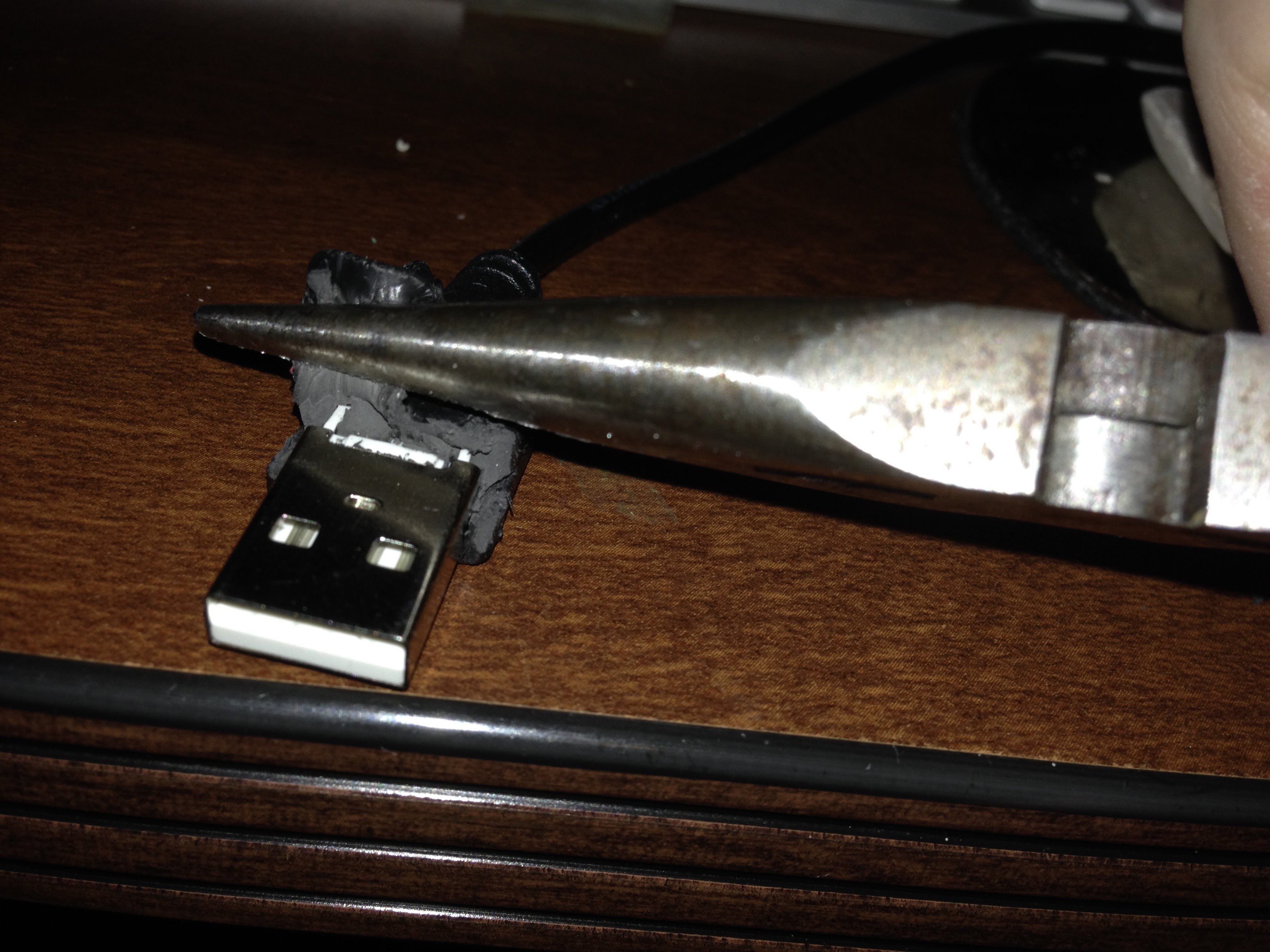
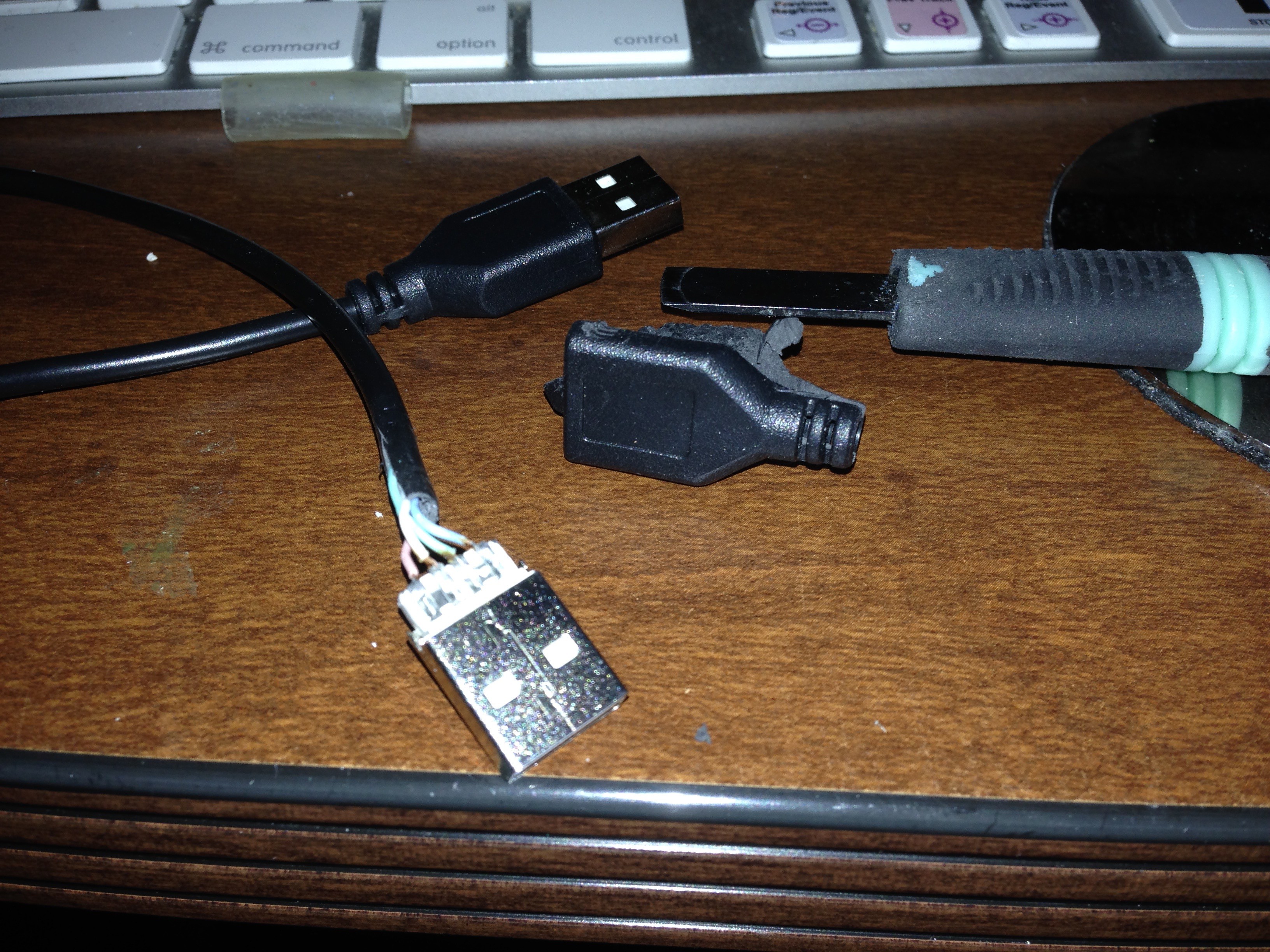
I ended up modding the USB cables as the strain relief was too long to fit properly. With a knife, I carefully cut away the plastic revealing the wire. This also lets me make the cables the length that I require.
![]()
![]()
![]()
I did cut a notch into the shell, this will be fixed in the main file so future versions will not require a mod. The hollow plastic was filled with hot glue to keep it from delaminating more after the cuts were made. You can also see the modified USB cables in place.
![]()
![]()
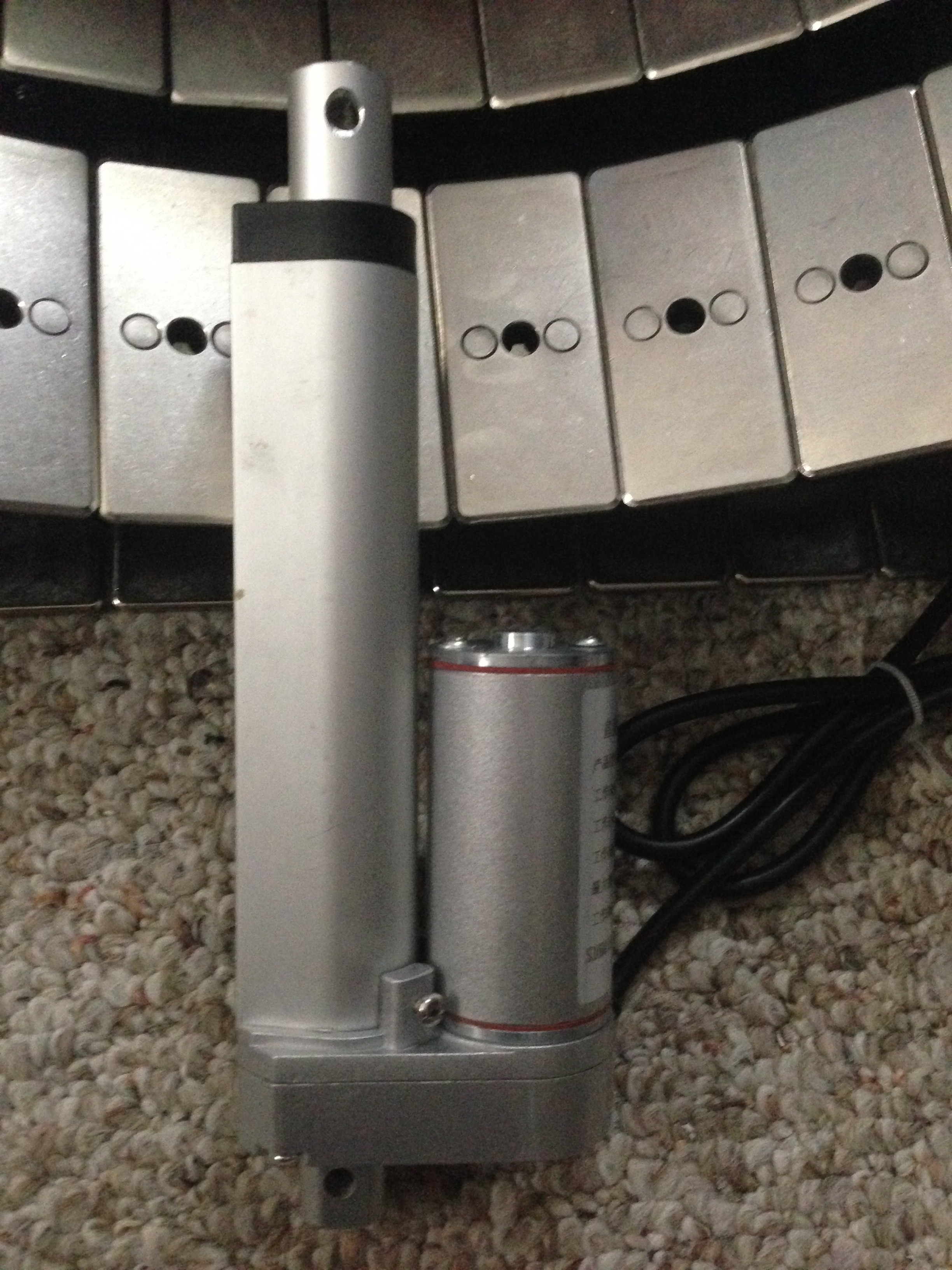
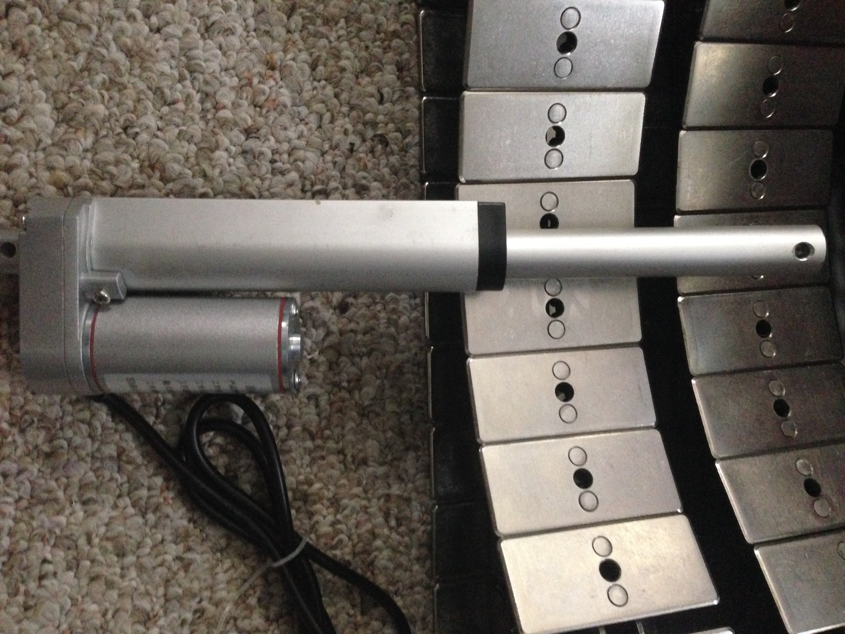
In other news, I have received a very wonderful linear actuator. This will be what is used to raise and lower the main body of PAL. It moves 6 inches, and with the use of a speed controller should do the trick.
![]()
![]()
Sorry for the picture heavy update. Work has kept me very busy this last week and I have not had a lot of time to work on PAL. I am also making some modifications to the lower chassis design to accommodate the much nicer tracks that I made the other day (seen in the images with the linear actuator).
Currently I am on the fence if I want to print the head in a higher resolution and possibly give it an aluminum paint job to match the rest of the body, or if I will just leave all the plastic looking like 3D printed PLA :)
As always... more to come as I find time !
-
Another option for the track
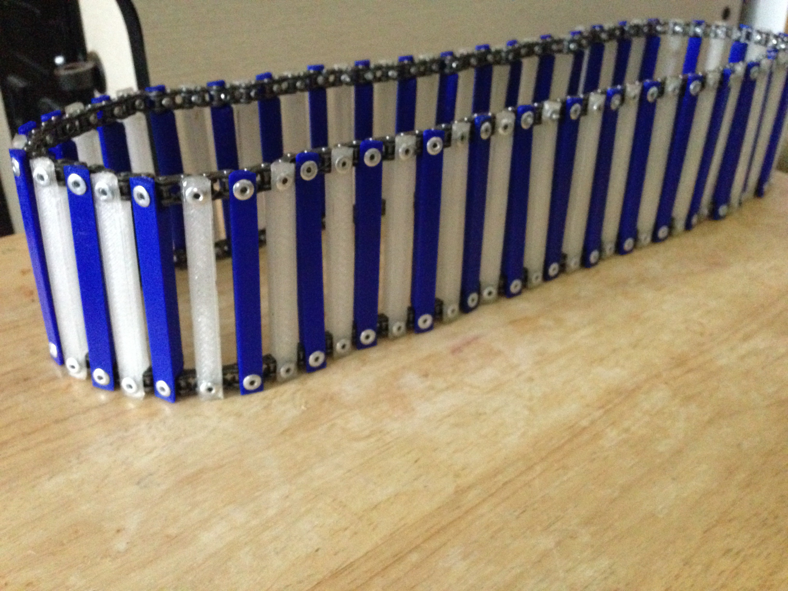
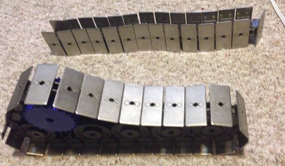
07/26/2016 at 06:53 • 0 commentsI won 10' of table top roller chain on ebay a while back for 50 dollars (including shipping to Alaska). Normally this chain is used for conveyor belts, I was thinking it could be put to another use. A wonderful new track :)
Well, it arrived today. I used a 'C' Clamp and a 5/8" nut, along with a chain breaker tool to build two tracks with it . The nut is used so that you can use the 'C' clamp to press the pins back into place without resorting to the use of a hammer. I also used some wheels to see how it "felt" in the shape that I want as well as tested how much force it would take to move such relatively heavy track. The motors I have should move it with no problem.
The chain is larger, 1864EAK3 made by Rexnord. Each track is made using a 3.5 foot section of chain, with 3 feet of chain left over for repairs or other uses later.
I know it isn't a totally 3D printed solution, but I like looking at all the options :)
Pros:
- Doesn't twist
- Easy to work with and repair
- Very solid
- Much faster than 3D printing a solution
- Looks amazing
- Heavy - moves the center of gravity down for more stability
Cons:
- Heavy - requires strong motors
- Can be expensive if you do not shop around
![]() That's it for this 5 minute update :)
That's it for this 5 minute update :)Cheers!
-
Brain Pan - A place to fix the brains and optics
07/18/2016 at 09:04 • 0 commentsThis is an older log that was saved in draft, publishing it as I want to keep all thoughts on the project transparent. I have since finalized the design and when I get some more time I am going to write the log entry :)
The head also has a design change, for the better I think :) More to come!
===============
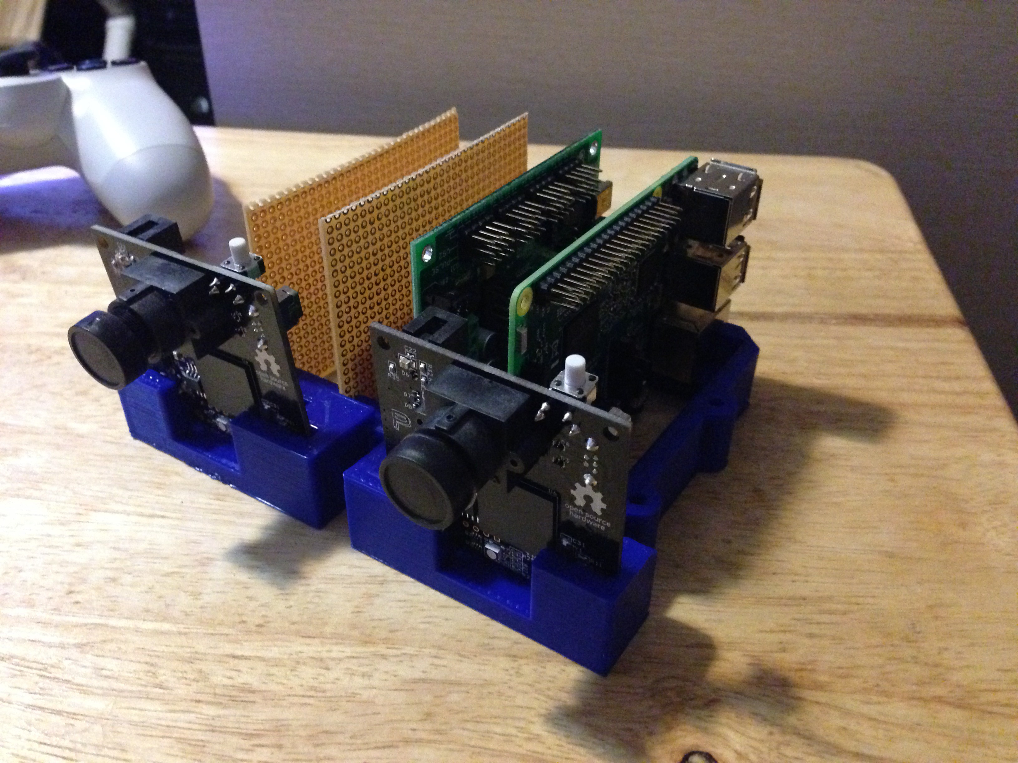
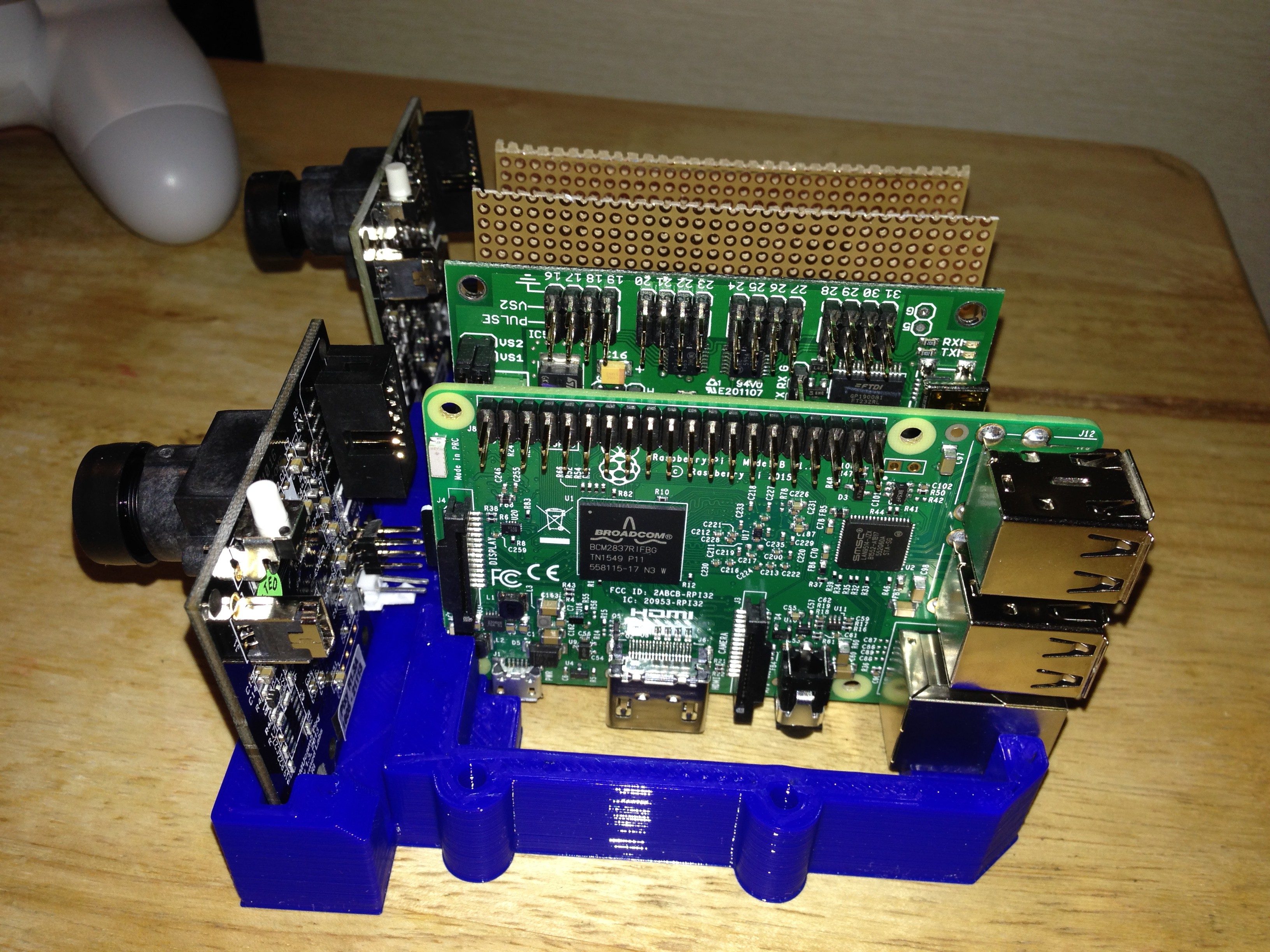
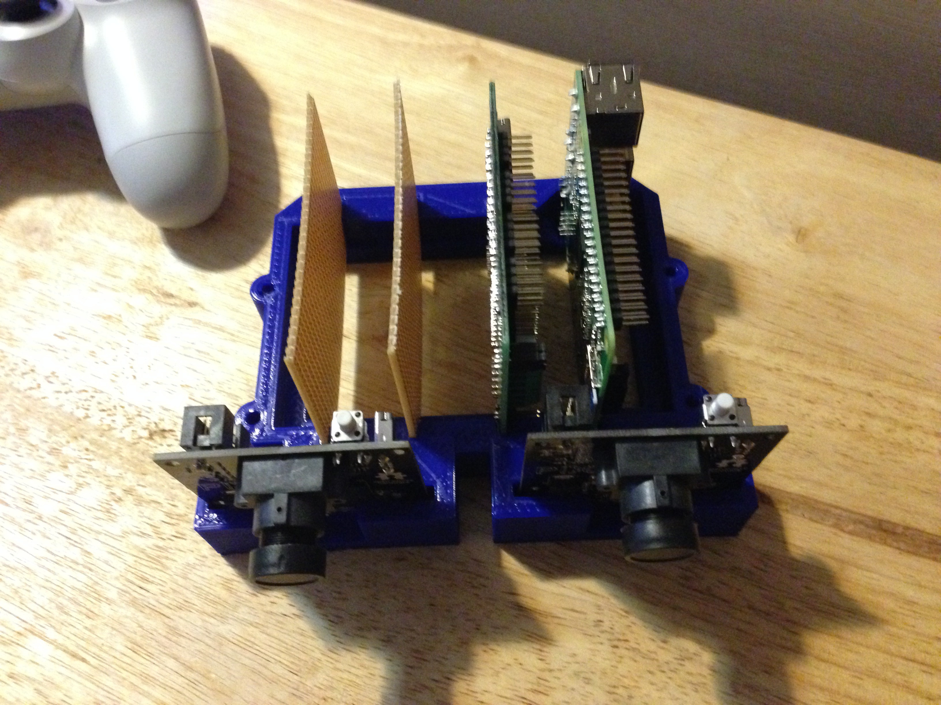
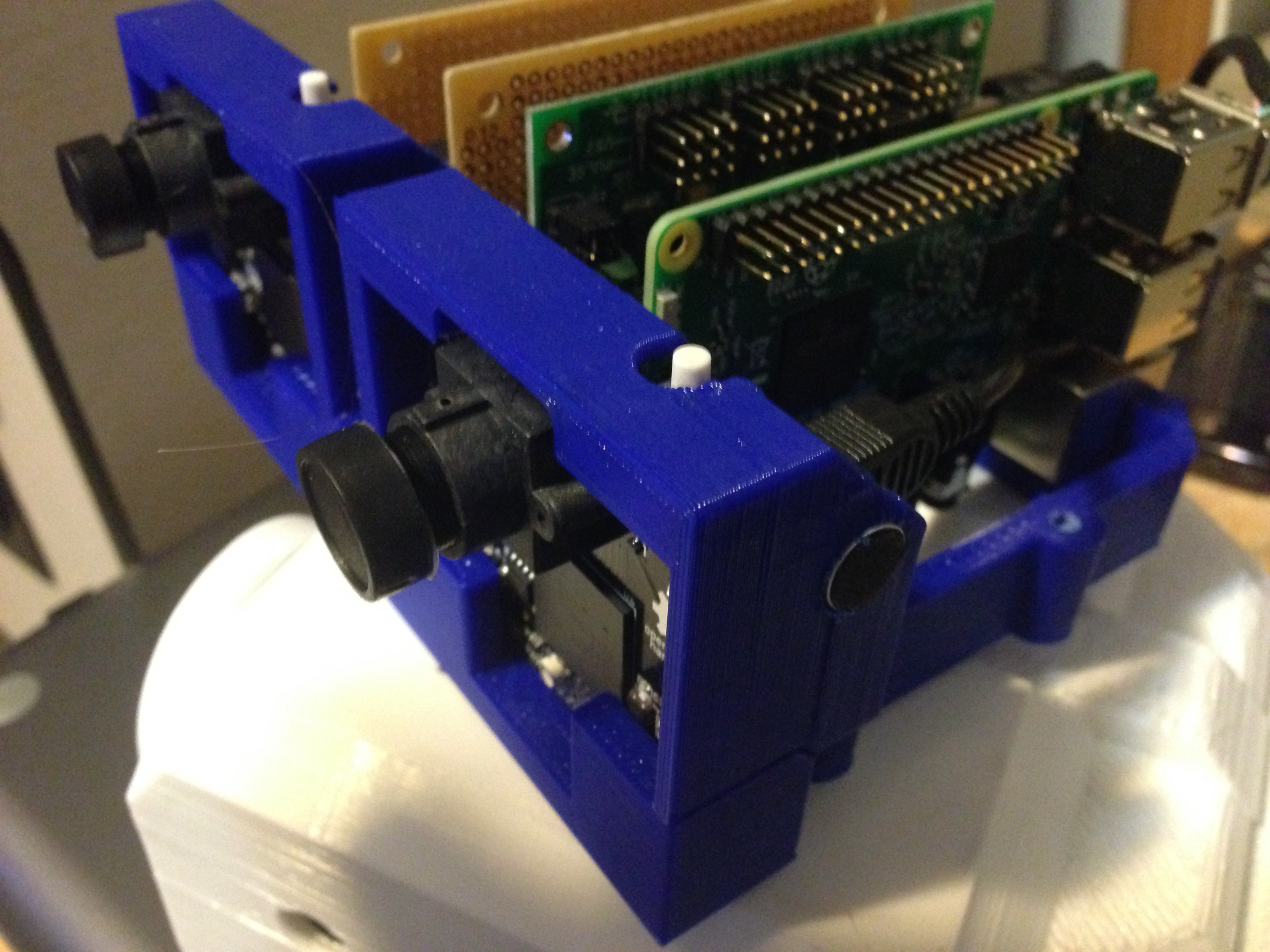
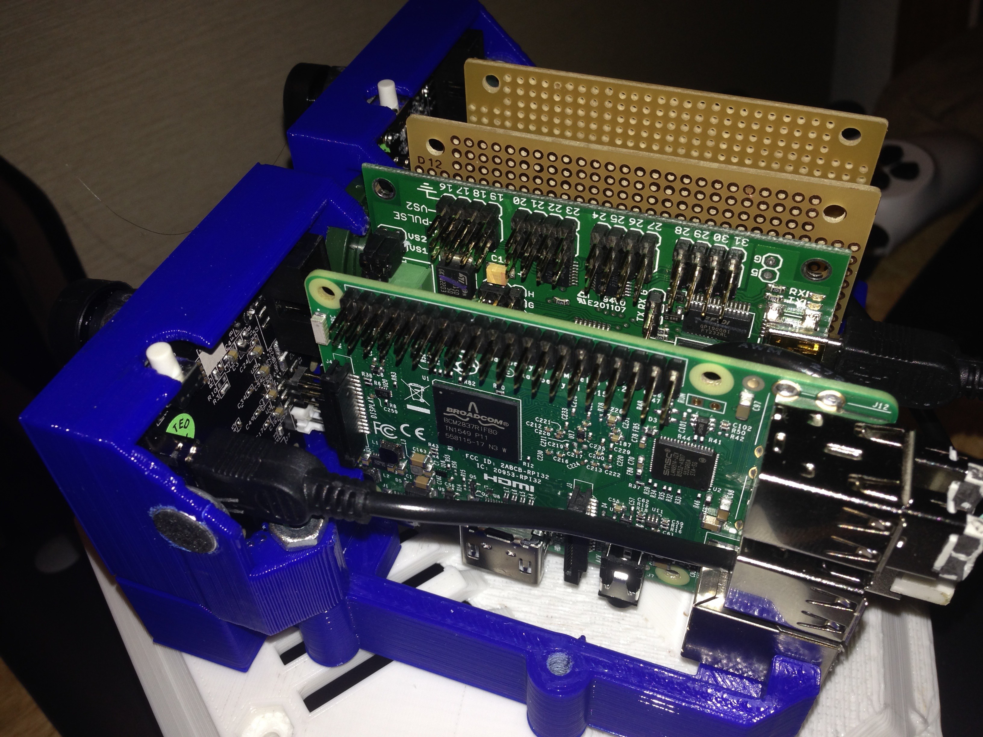
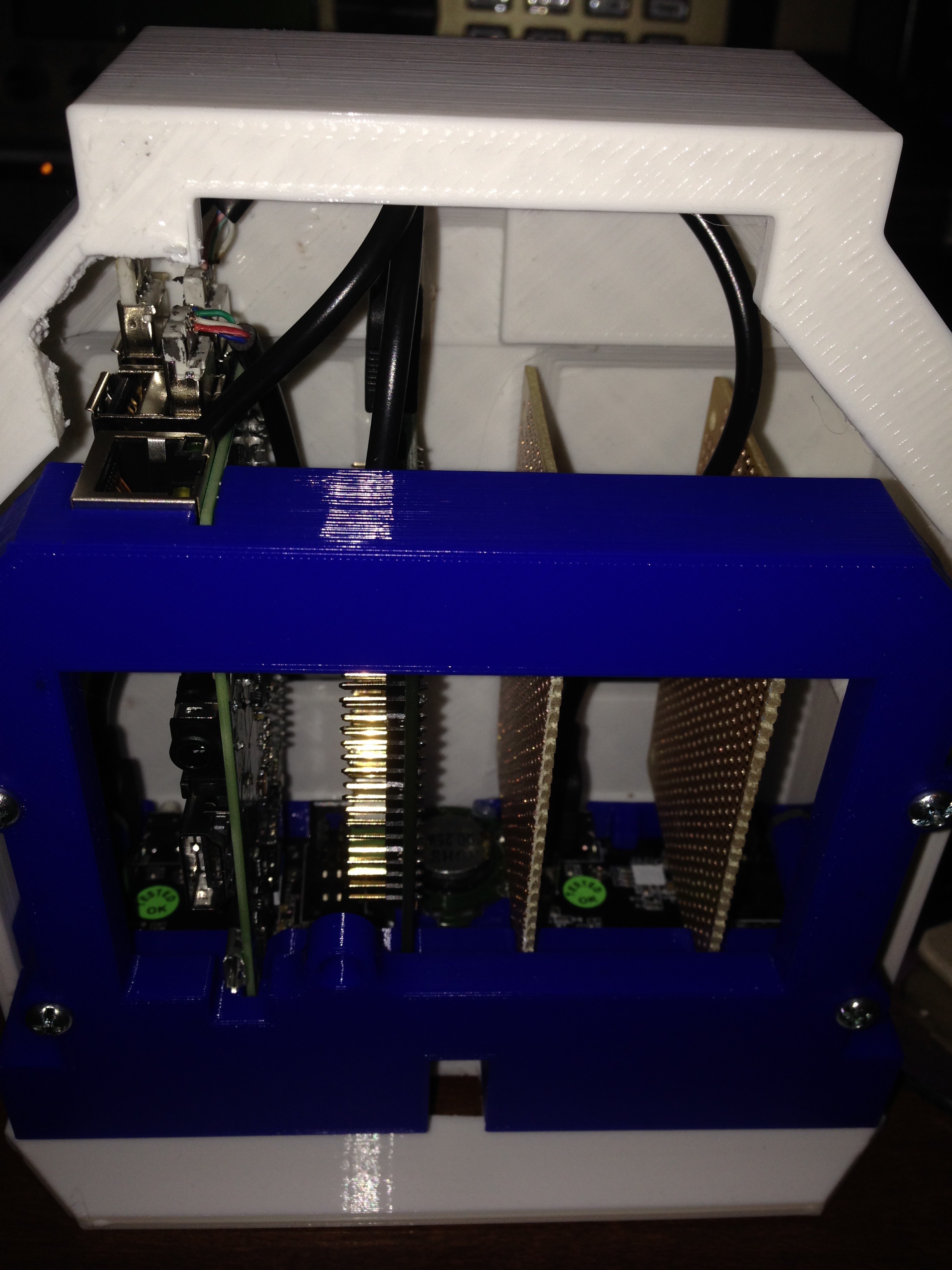
A brain pan... the skull, or rather, the inside of the skull. This is a place to fix the optics and some of the PCB boards, including a raspberry pi 3b and a lynxmotion servo controller. It will also house the speech and audio recognition system (represented by the two blank boards).
I did have to do a tiny bit of minor trimming on the raspberry pi slot, along the back corner to allow room for a small smd part. I will adjust the file accordingly so this should not need to be done on future prints.
The idea is to use this as the foundation to attach the other components, IE. the outer shell and servo mounts for the eyebrows. The components are not bolted/glued/mounted into place in these photos, so there is some wobble on the optics. This will be remedied with the addition of a bracket that bolts into the front set of mounting holes.
![]()
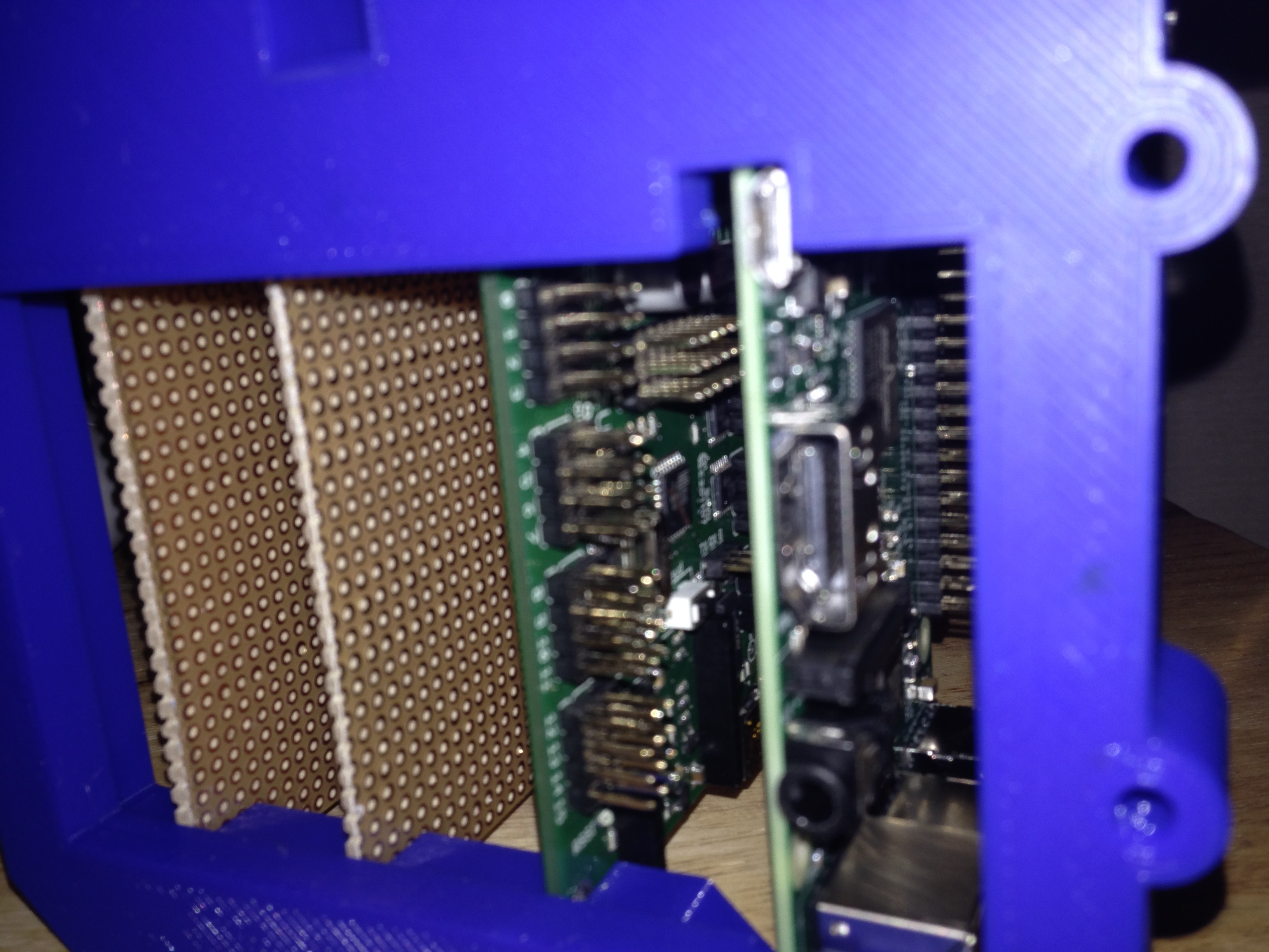
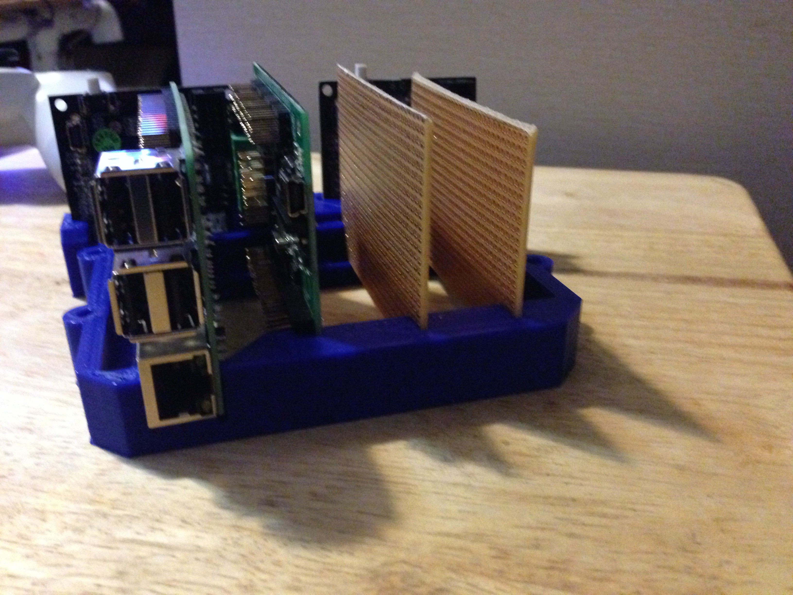
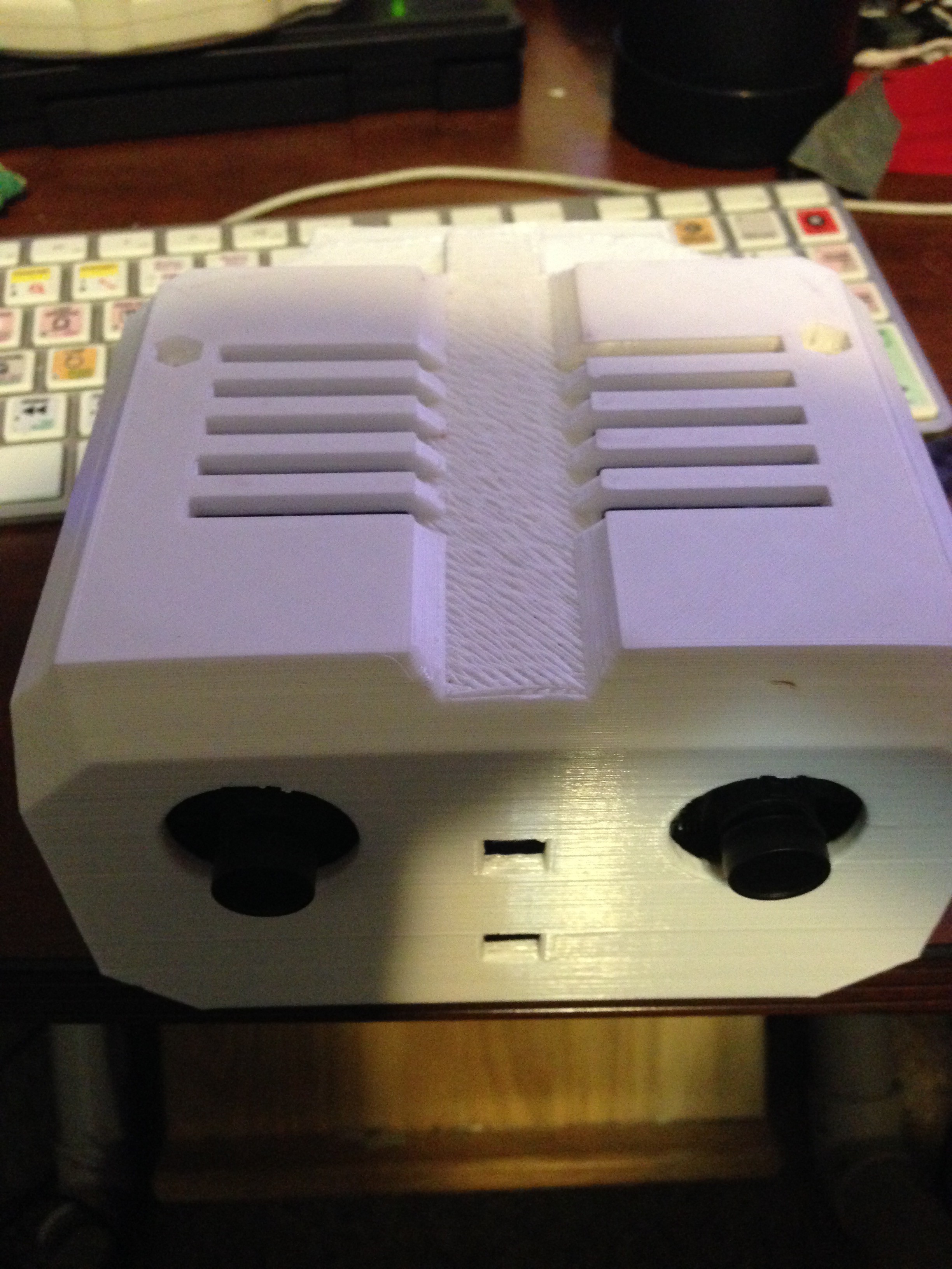
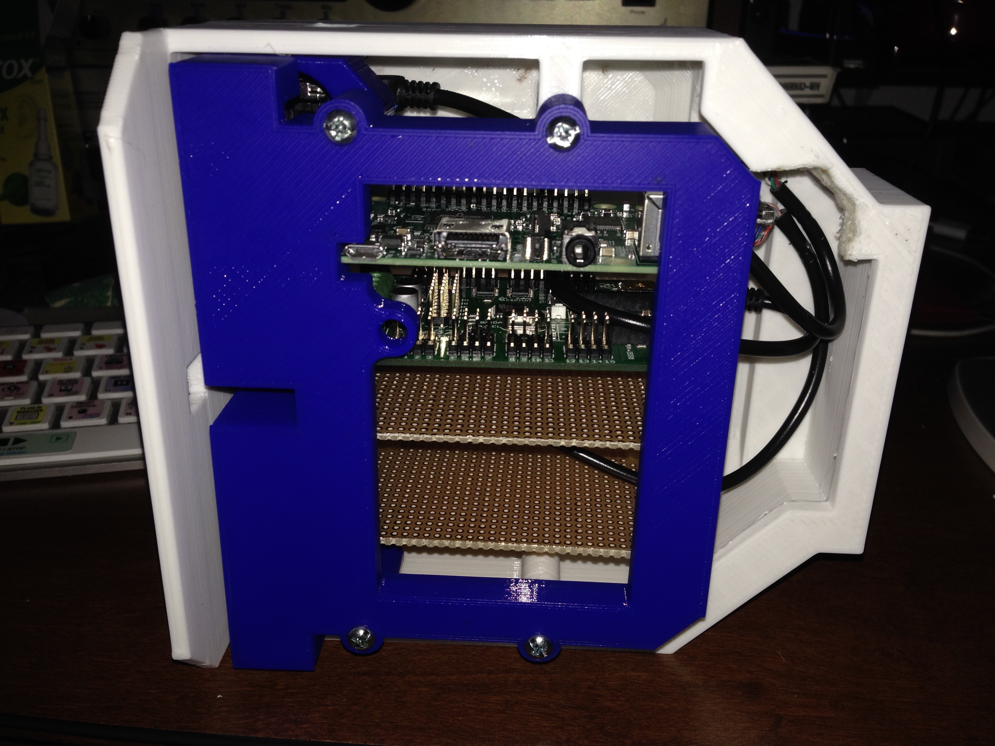
The bottom, all ports are accessible.
![]()
![]()
![]()
![]()
There is no stress on the boards, the two PCB are simply warped from being stored for a long time.
The file for this part will be uploaded, I test fit it for both the Rpi2b and the Rpi3B. Both fit properly.
-
Track 1... One more to go
07/16/2016 at 20:38 • 0 commentsThere are 76 of the treads printed for each track, with one tread every other link. The result looks like this.
![]()
To connect them, simply use a pop rivet that is the proper length to go through the tread and the chain link and out the other side. The only issue I ran into is the occasional rivet that would either break off leaving a small spike that I need to ground off or in the rare occasion where the rivet would not break at all and the plastic tread would break. The track turned out extremely flexible :)
I am compiling a list of parts as I go, and will update that list with a note where that part goes as things are built.
Sadly, my lab assistant (pictured below) doesn't want to build me another track, cornered him to ask why and he mumbled something about another 152 rivets is not for today. :p
![]()
Cheers :)
-
3D Printing the Track - The Tedium ^^
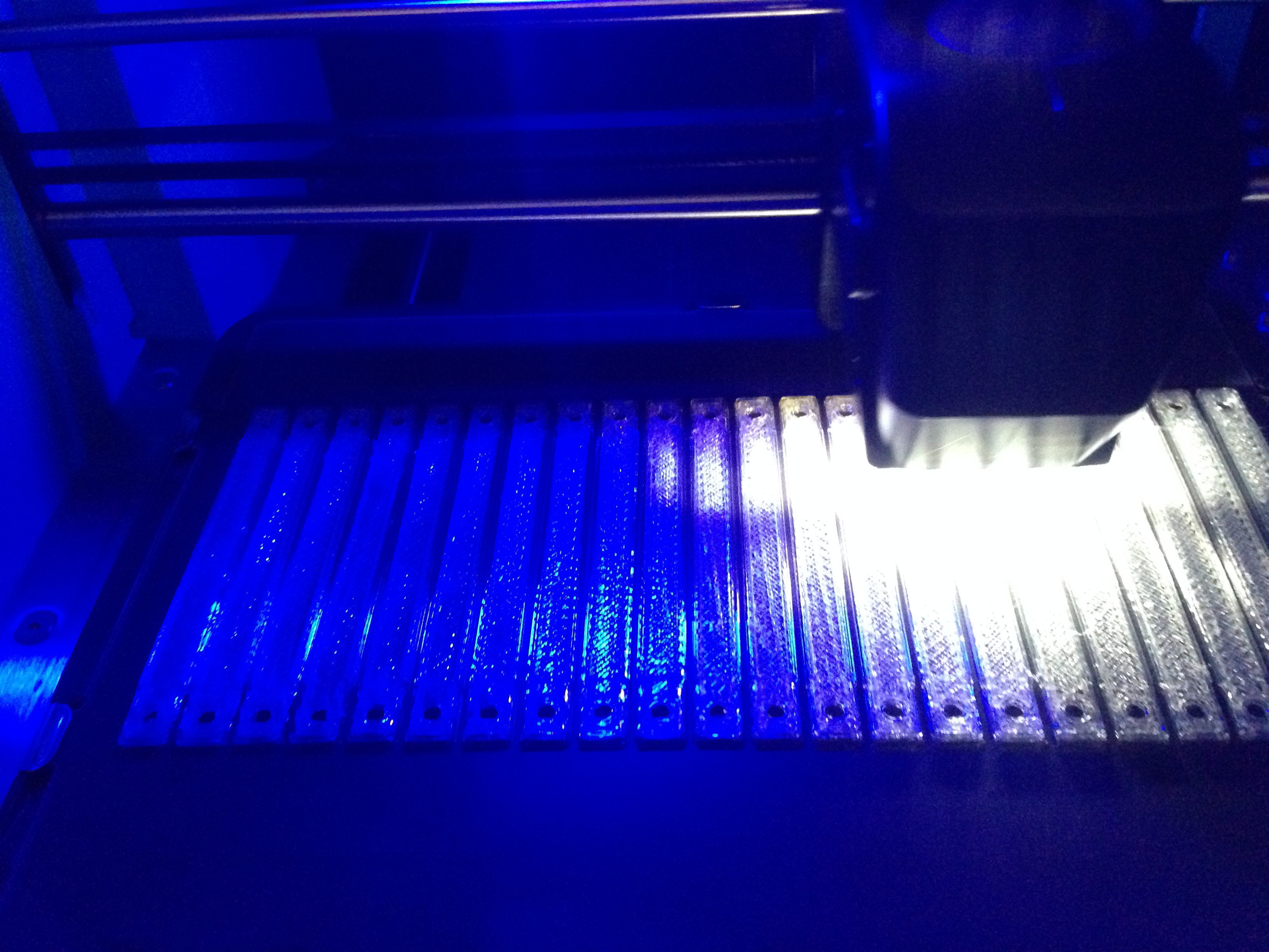
07/14/2016 at 20:34 • 0 comments8 sets.... that is the number of times I need to print for the track. I am going to attach the file to the files location as soon as I am done. The file contains a single part for now. I will design and print the sprocket soon. Each of the parts is mounted onto two #25h roller chains using a medium rivet that is 1/8" (3mm) wide and 1/4"(6mm) tall on each end. #RMA1/8IP from ARROW.
You only place the parts on every other link, leaving a 1/4" gap between. This allows the track to roll properly and gives the sprocket a place between to grip the track.
8 prints*22 parts per print + four pieces of 3 feet of chain = two tracks with some spares left over for repairs. More pics and files to come soon :)
![]()
P.A.L. - Self Programming AI Robot
P.A.L. : Personable Autonomous Learning - Self Programming Robot that learns and grows - Each robot developes a unique personality.
 By cutting off the one side of each caster, they have enough clearance to allow the parts to roll comfortably. The thought is that in the final design it will end up looking something roughly like this. Please note, I am waiting on sprockets to arrive in the mail, so those parts are substituted just to give an idea of the basic shape.
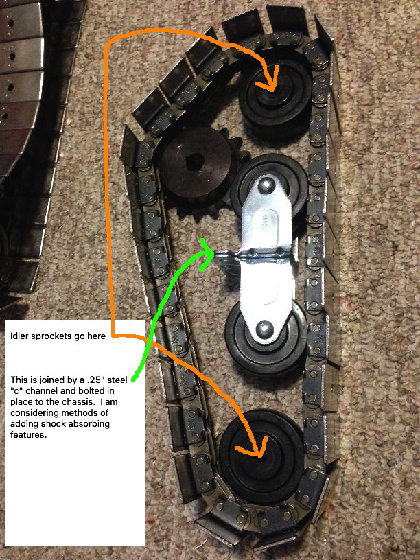
 That is one blank stare XD
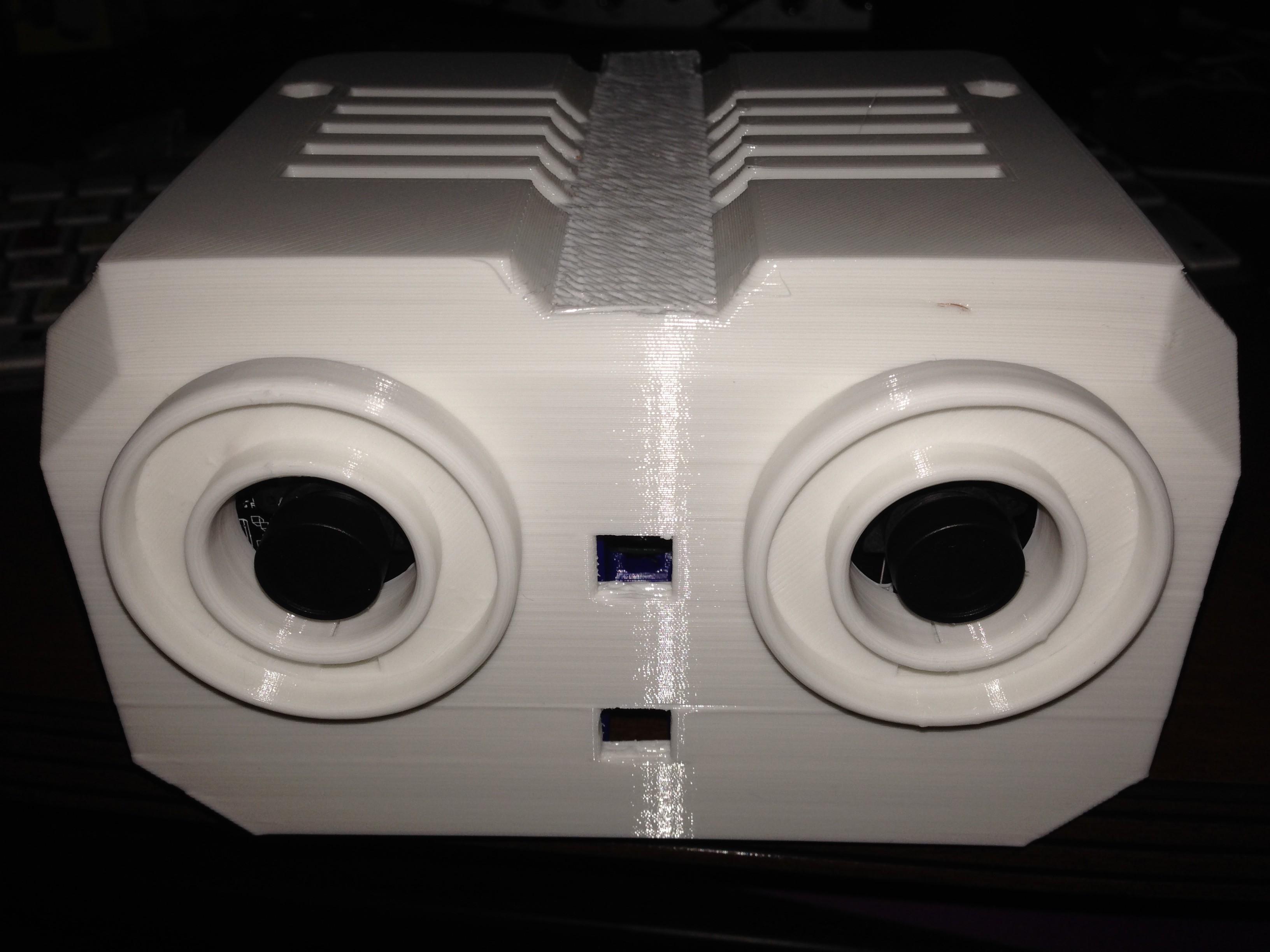
 That's it for this 5 minute update :)