ThunderSqueak
-
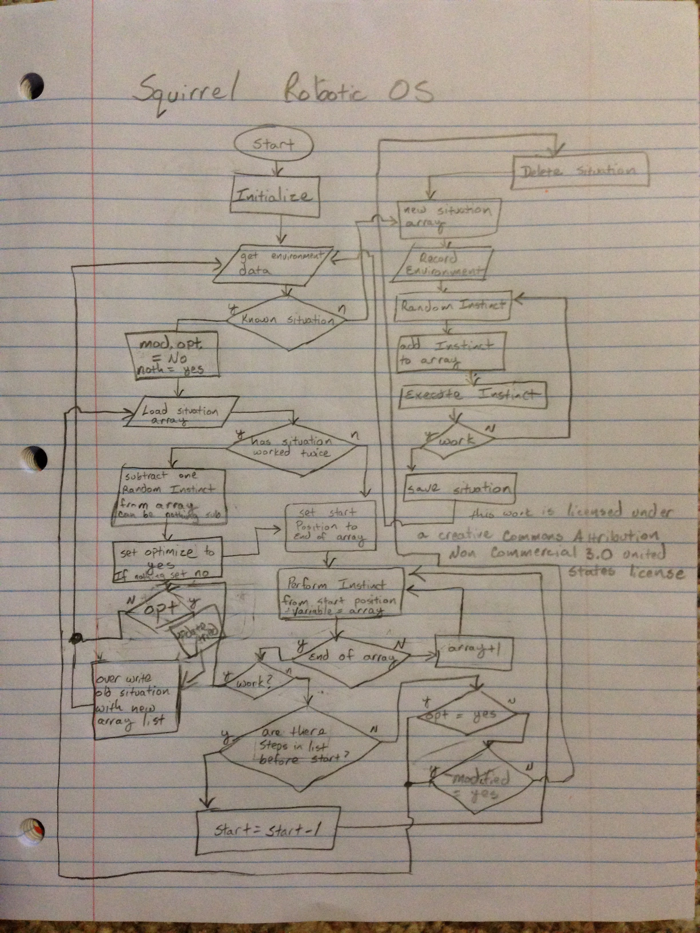
Squirrel Robotic OS flowchart
07/02/2016 at 00:15 • 1 commentThis is an image of the initial flowchart for the robot's "OS". Instincts will be a list of basic actions such as moving an arm 10 degrees (I am going to put them in 10 degree increments at first for each motion), or saying a word from a known word list. The flowchart below is not all inclusive, but was a rough outline to give some direction for the code. There will also be some housekeeping functions such as updating mood on a success or failure.
I know this is a very simplistic learning system, but hey, we all have to start somewhere :) To handle the "nothing is subtracted" during optimization, I was simply going to add 1 to the random number generation. This way, if there are 15 elements in the array, and a 16 is rolled, then nothing is subtracted.
The situation file will be of a standard text file format, very human readable.
<situation number> <worked more than once> <sensor 1 status> <sensor 2 status> <sensor 3/etc status> <comma separated list of instinct numbers in array>
The instinct list will include things like
<instinct number> <sub system designation number (servo, voice, etc)> <actions to send to that device in a command string>
All actions are sent over and received by a standard serial communication. This is to make things easier to monitor and keep everything the same should I need to troubleshoot. The system can control 32 servos and has a number of other GPIO pins that can be addressed in this way.
![]()
-
Picked up a new tool for the build and OS name
07/01/2016 at 21:30 • 0 commentsWhile out and about, I was thinking about the frame of the robot and how I wanted to construct things. I want the body to be light and strong, so I am going to build as much as I can out of aluminum and 3D printed parts. The question that came to my mind is how I plan on connecting everything.
I weighed the options, you can bolt things together. Spend a lot of time drilling and tapping holes. Screws could possibly be used. Brazing is also an option but I didn't want to mess with that.
Enter the pop rivet gun. Nuts and bolts are fine, but for a fast and cheap solution, I think I will use rivets to join aluminum components where the parts are not to move. The gun itself was 20 dollars and 120 rivets was just a few dollars more.
In other news: I decided to name the new OS "Squirrel".
Should be fun :)
-
linear motion
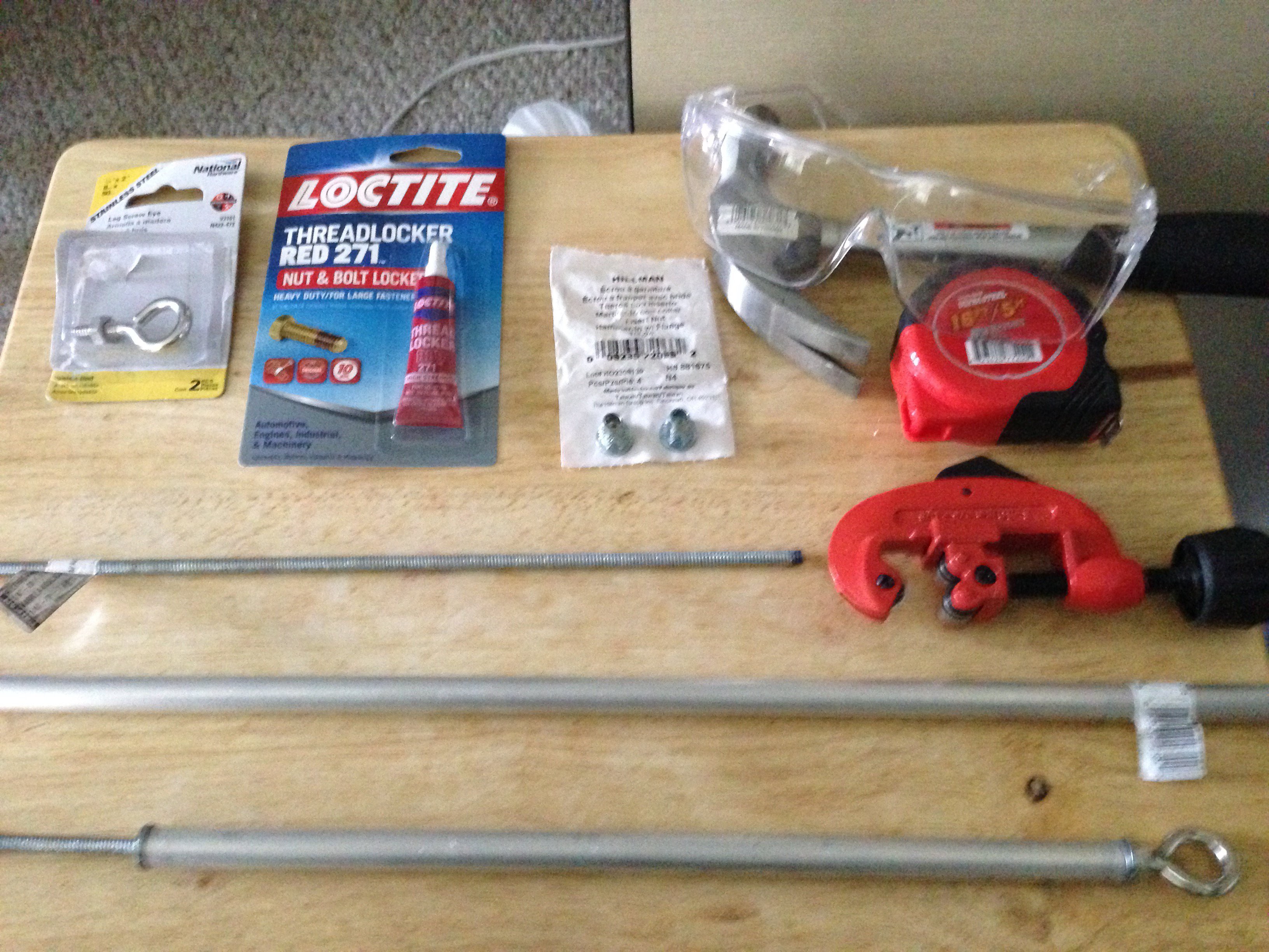
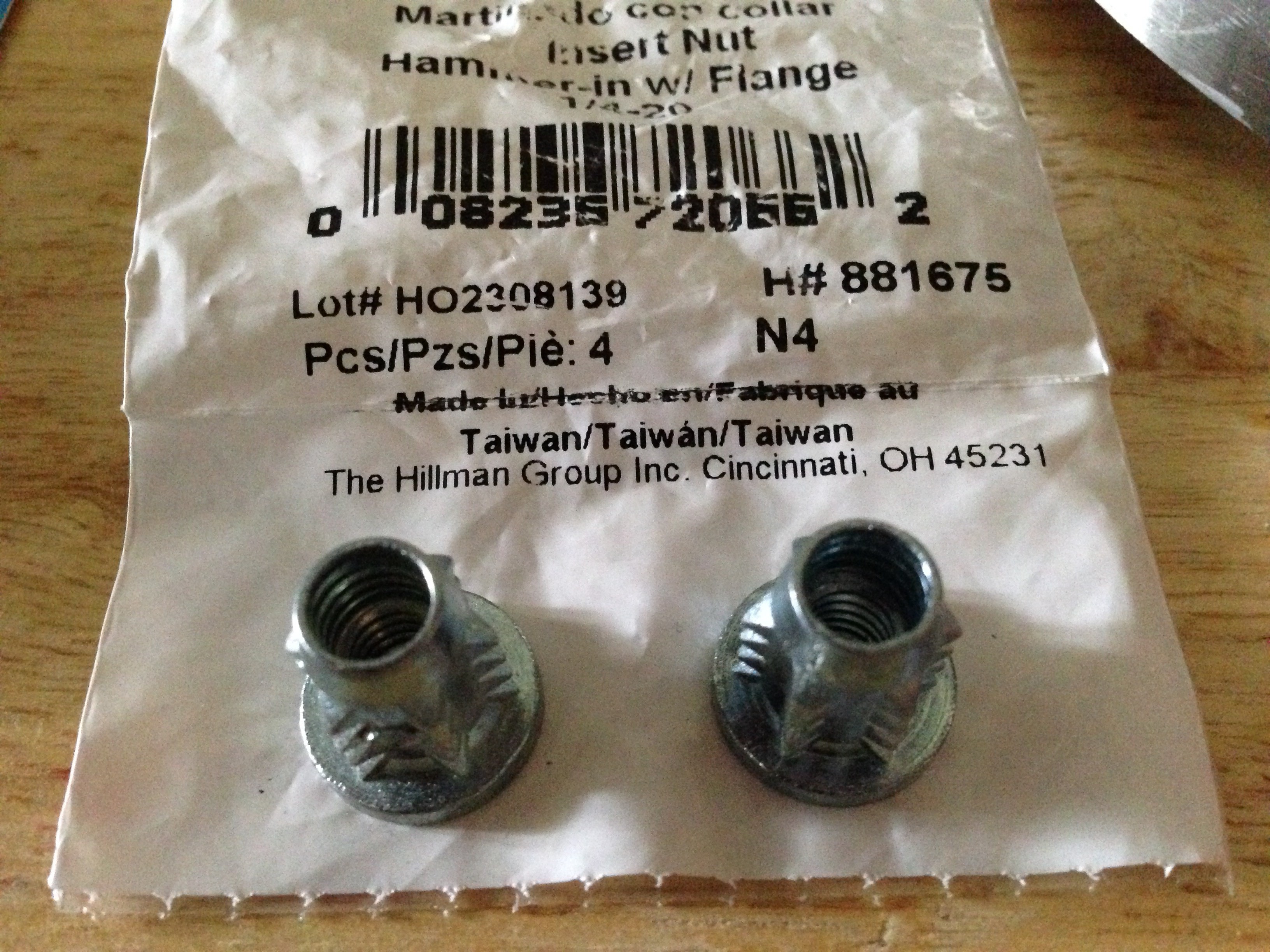
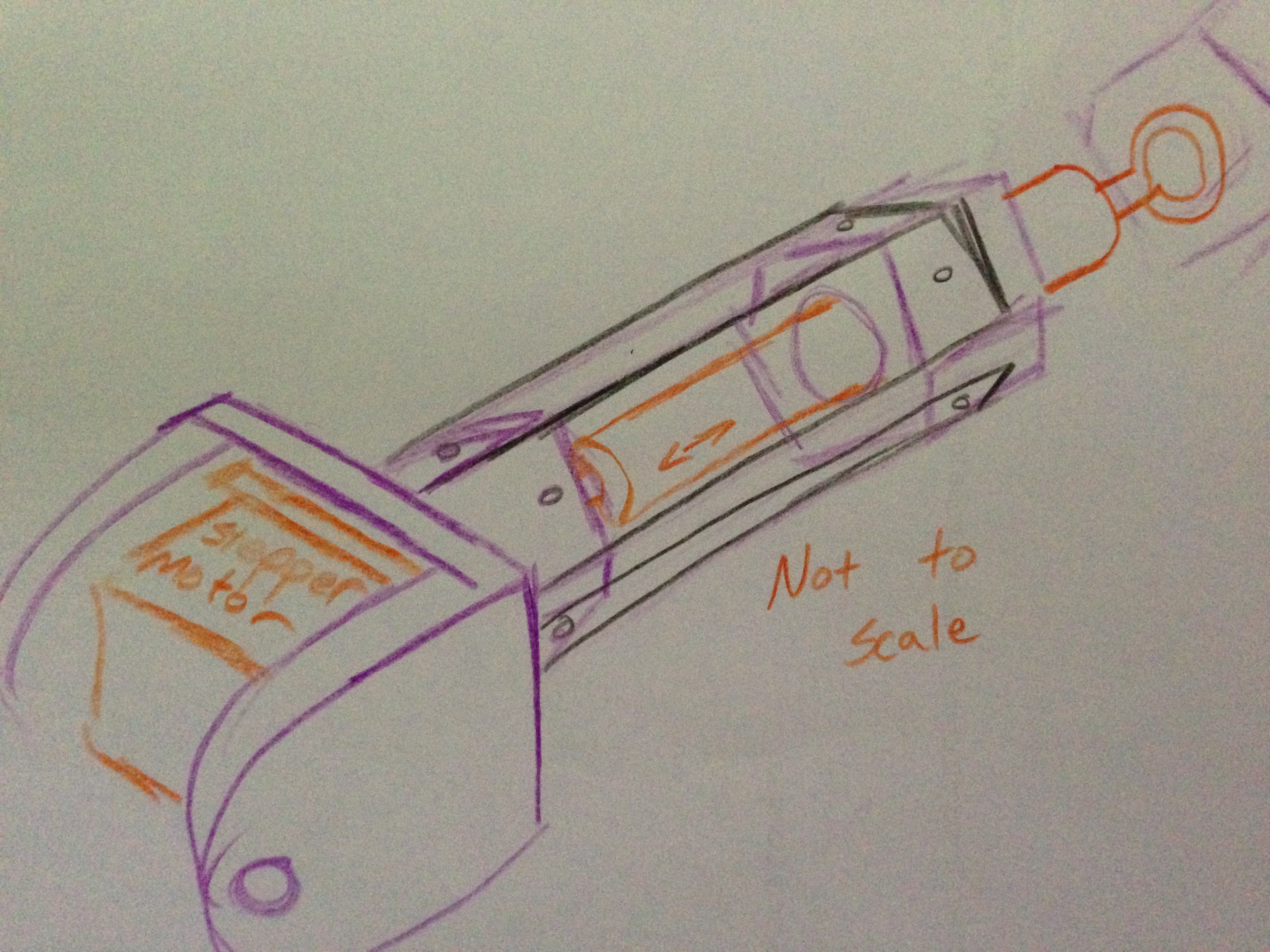
07/01/2016 at 02:02 • 0 commentsToday during my lunch break I was thinking about linear motion, linear actuators, and linear servos. Many of them are very expensive and heavy. After some thought, I may have a solution... using a half inch aluminum pipe, 1/4"-20 all-thread rod, some threaded furniture inserts that are 1/4"-20, an eye bolt 1/4"-20 with matching nut, and a peice of 1/4" angle aluminum. Along with some 3D printing it should be acceptable for light duty work.
![]()
![]()
![]()
![]()
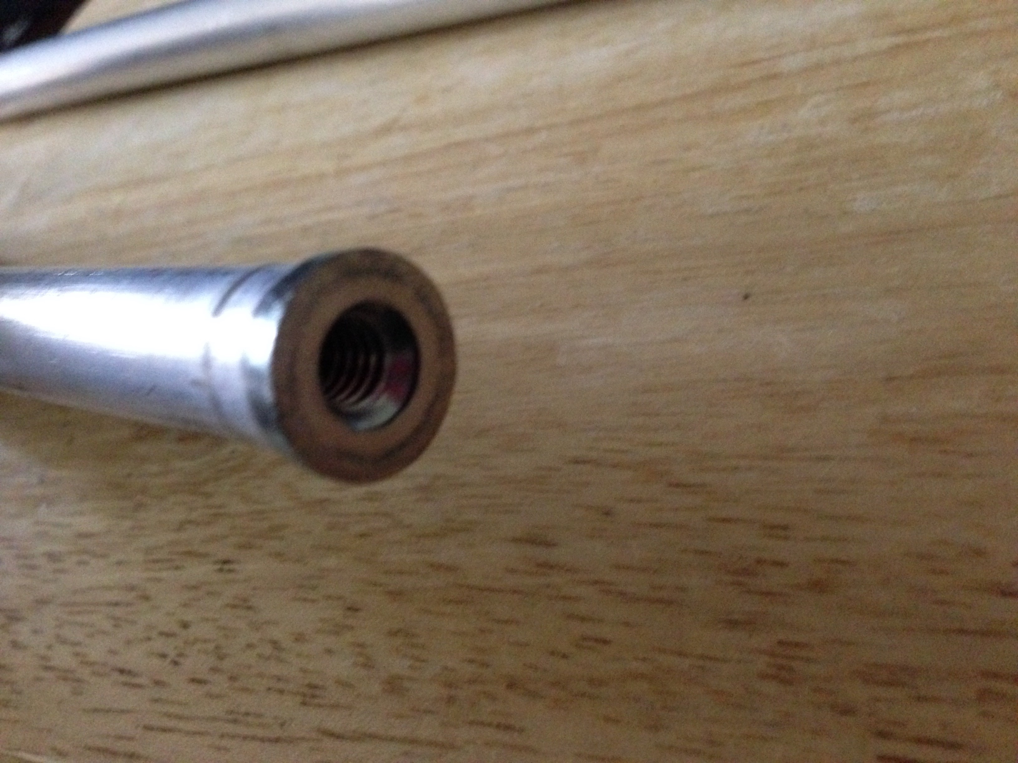
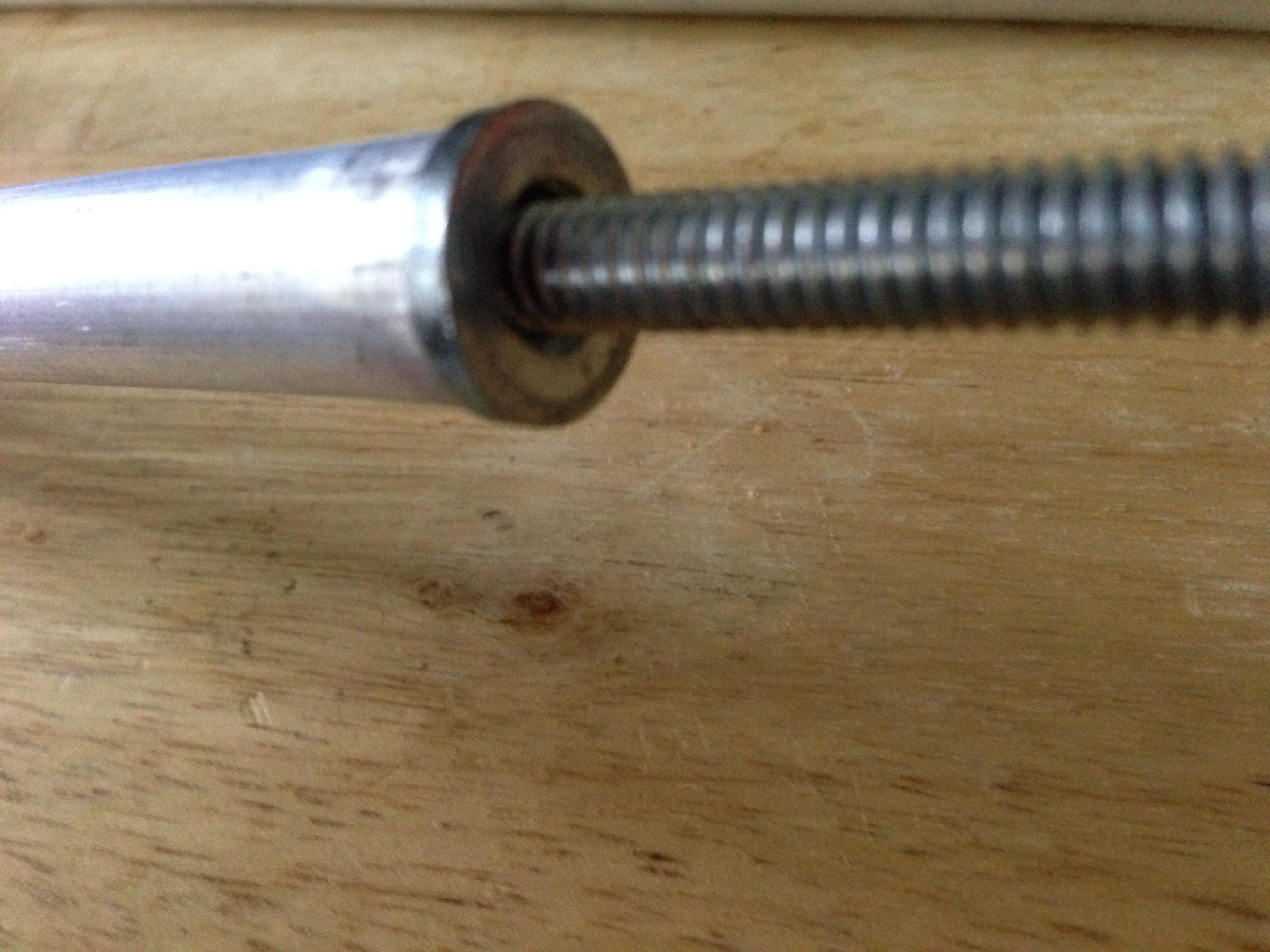
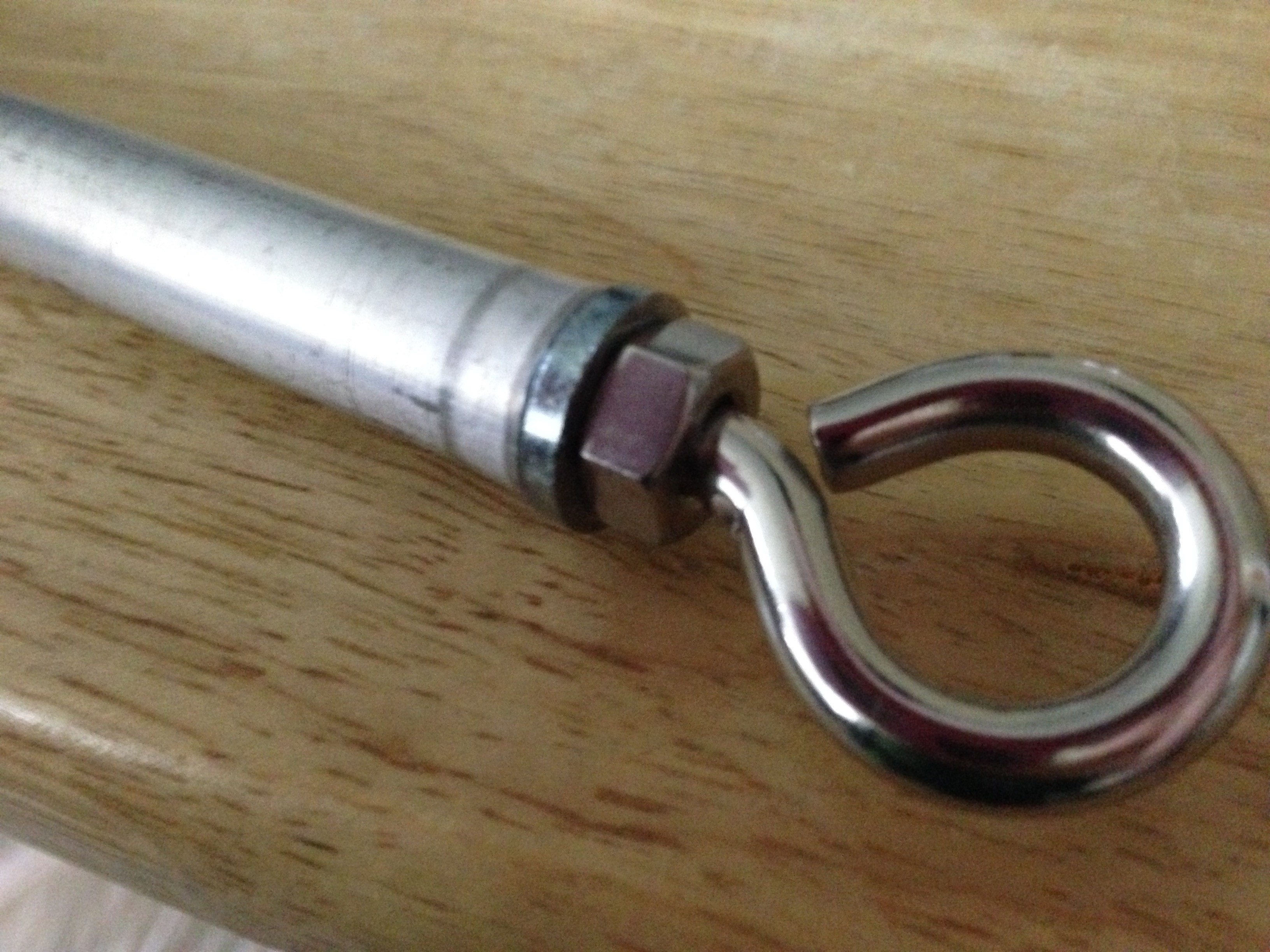
wearing some eye protection, I hammered in the inserts into a piece of pipe cut at 12", then simply threaded in the eye bolt and the all-thread. the locktite is for the eye bolt. after I finalize the design. Without the motors, it should come to about 6 dollars per linear actuator. Since these are not meant to handle a lot of stress, the motors should be able to be placed in line with the all-thread rod and coupled directly to the motor shaft.
![]()
![]()
![]()
When my 3D printer is back and functional, I will print out the motor mounts and attach the two angle iron sides. I picked angle iron so that there is a "slit" along each side, this will allow me to put in a screw near the top and bottom of the piece above and add some switches to designate the end points should be necessary.
This is a quick rough sketch of the initial idea, the black "rails" are capped on each end with some 3D printed parts. Any limit switches can then be easily fixed to the sides of the rails by drilling and tapping the angle iron.
![]()
Stepper motors, servos, or DC motors could be used depending on which mounting solution is chosen for the motor side of the 3D print.
cheers
-
The nature of AI - a few thoughts
06/29/2016 at 09:43 • 2 commentsI was trying to go to sleep after a day of laying out VLSI ( my day job ) and this thought came into my head.
What is AI, it isn't some pre- programmed set of mimicry. What is a true robot? Does a true robot have any sort of human input? When I say true, and I know this is a debate for some (much like "Mac vs PC" or "Coke vs Pepsi"), I mean a robot should be like a mechanical animal, it has a base set of "instincts" and uses those to overcome obstacles or puzzles in its environment. It should see the world and learn using its sensors. It should try random solutions when no known solution exists, then when one is found save that solution to try first the next time a similar situation occurs.
This is how animals learn, and it is what I want to do with the OS of P.A.L.
PAL should be able to sense a stimuli and respond accordingly, if that stimuli is being stuck into a fenced area, or hearing a spoken command, it should be able to respond in a way that makes sense. The initial OS will be a set of "instincts", or actions to try. These actions will not be tied to anything, they will just be that... actions. Such as Go forward, go backward, turn left, turn right, reach an arm out, reach the other arm out, reach two arms out, try different angles, yell for help, etc. There should also be a "baby duck" syndrome included where PAL sees humans as caretakers, at least at first. PAL will also have a place to "eat", that is a charging station. I have no intention of showing PAL where this station is, but instead intend to have in the instincts algorithms a value that is "good", "indifferent", "bad". Charging would be one of the good things, as is being content.
This could also be used as a reward system for PAL when a question is asked and a web search performed. If the answer is correct, you can tell PAL "Good job" and the good value will rise, to the point where PAL likes answering questions. If an incorrect response is given, such as a math problem, you can let PAL know that as well.
In the end, I do not want PAL to be some glorified remote control toy, I want to create a true, even if simple, AI learning algorithm that tries things out and discovers on its own what is successful. I want PAL to learn from its mistakes.
In a side thought, I am also going to include a panel on the front of PAL that contains an LED for every system, for each servo, etc. This will let me know with a visual inspection which systems are being activated and when. I know it is a bit old fashioned having a robot with a chest full of blinking lights, but I did grow up with the scifi of those eras.
![]()
Sorry for the late night rambling, but I wanted to get these thoughts onto paper before I slipped into a sleep and they were forgotten.
-
Lower Chassis
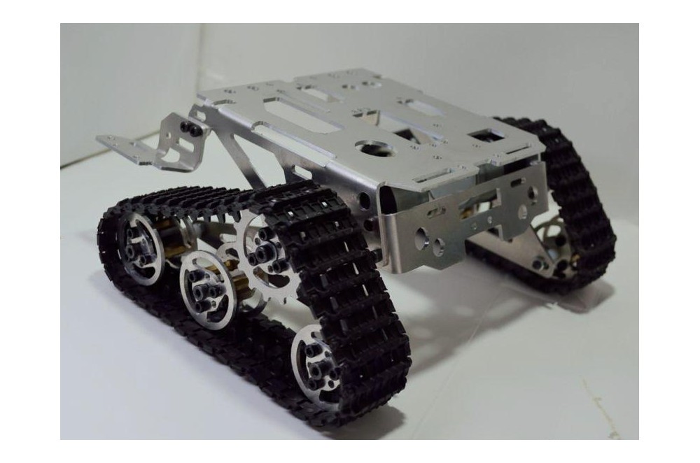
06/27/2016 at 23:12 • 1 commentI was considering options for the lower chassis, After a lot of thought, I am considering something along these lines.
I also have decided to change the main computer to a Rasberry Pi 3 B, I know it will use more power but I think the added power should be helpful as the system gets more advanced. It also has the added benefit of already having bluetooth and wireless built in. This should free up USB ports.
The upper chassis will be made from aluminum stock from the local hardware store. The body will bend in the middle with a single linear actuator made using a stepper and belt configuration, much like you would see in a CNC machine. The linear actuator will cause the body to stand up or collapse as needed for balance.
![]()
-
3D printer died today :(
06/27/2016 at 09:45 • 0 commentsWell, it happened. Luckily they are covering it under warranty. My Cel Robox 3D printer died, it won't communicated with the head. The feed keeps slipping. The thing starts up and shuts down intermittently, the last straw was the head began overheating out of control. They think it is the spring loaded connection pins and a sensor among other things that "apparently need to be upgraded since that printer was released".
I have enough printed out to begin assembly of the full sized head while I wait for the repair.
-
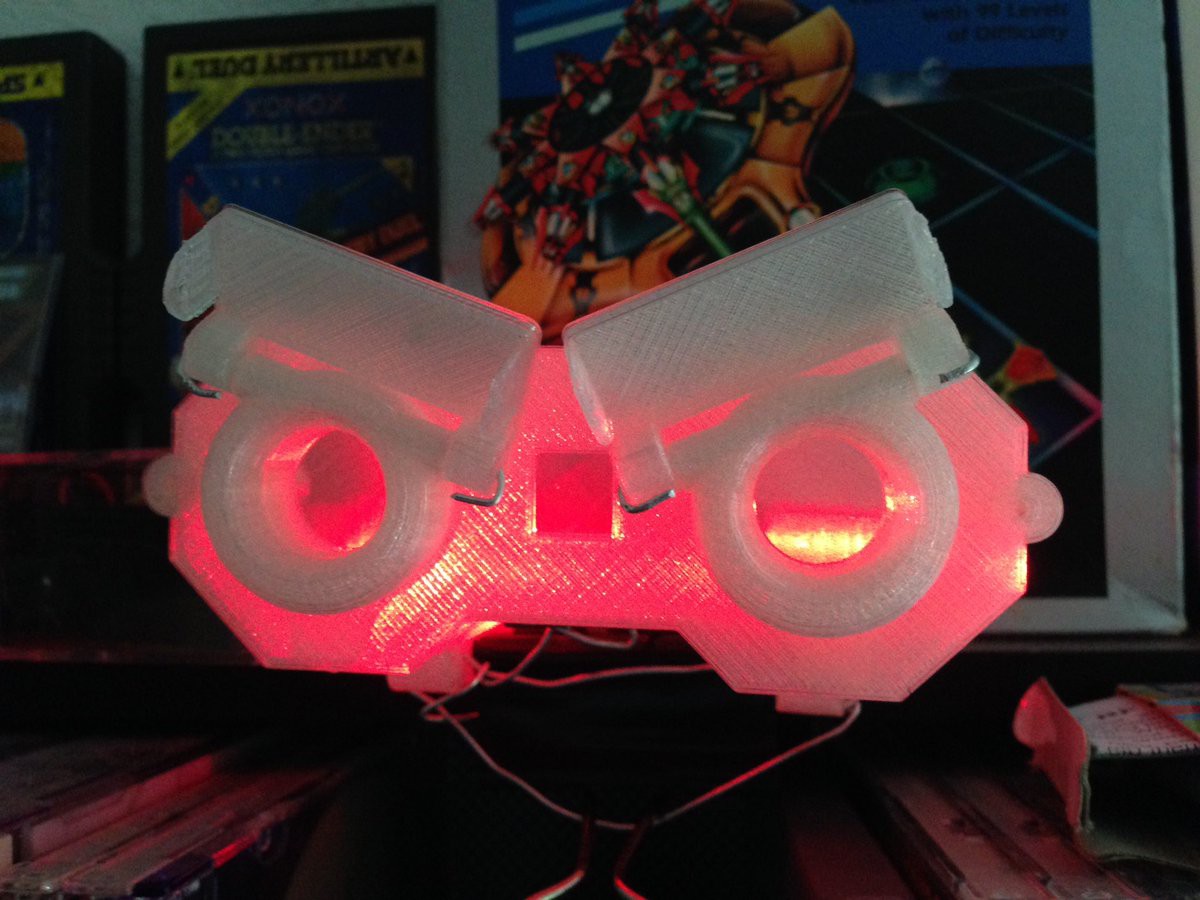
Coloring: another way for output
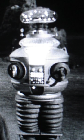
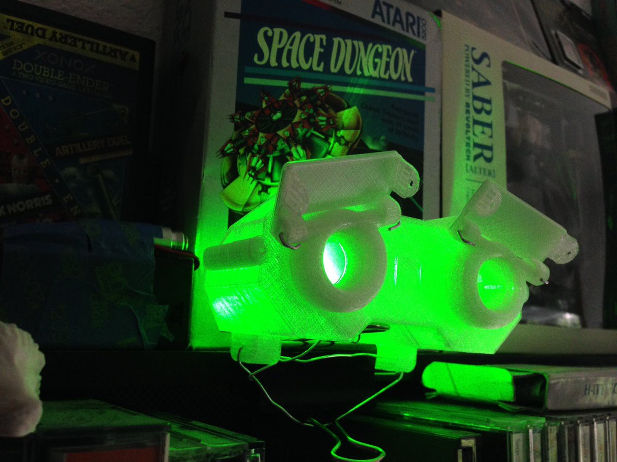
06/24/2016 at 20:52 • 1 commentI was thinking about including LEDs inside the clear PLA head to help produce a more "emotional" look to the robot. Here are a couple examples using the half sized head.
![]()
![]()
I sort of like it :)
-
Finalized the head case design
06/24/2016 at 19:03 • 0 commentsUploaded the 123D files for the head. The sizing is off, for the current version I am printing these at 1750% the size, as that is the largest my printer will allow. This means that the head_front is 199.84mm x 26.25mm x 80.84mm. What matters is that you print it all the same scaling and that it is large enough to fit the components.
After I decide on if I am going to use either a large servo or the cheep stepper motors I found, I will upload the neck components.
Any holes that I need in the final design I will cut with a hot knife and make a note of it in the log. I know I will need at least 2 small pushline holes in the head_front and one larger 10mm hole for wires in the Head_back. The tool used to "drill" the holes will be a wood burner with an x-acto blade. This should keep the plastic from cracking.
I did not include these in this design as placement of servos may change depending on where they are placed inside the head.
The head files are being printed in a clear PLA at a layer thickness of 30 microns for the final versions. The printer used is a CEL Robox.
Additional information:
The head is broken up into 3 sections, this is to allow me to print the entire portion, but more importantly lets me mount servos in the middle section (most likely hot glue) and put the electronics into the back section. The front section will hold the sensors and speaker.
I am releasing all files in this project under the Creative Commons Attribution NonCommercial License
https://creativecommons.org/licenses/by-nc/3.0/us/
-
Considering parts
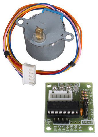
06/24/2016 at 10:20 • 0 commentsCurrently I am attempting to do this project using components I already own. Upon scrounging through my parts I discovered a dozen stepper motors and matching controllers.
28BYJ-48 Stepper Motor and ULN2003
![]()
I am considering using these instead of much more expensive servos to control the neck functionality. If I use this setup, I may end up using a microcontroller as a small dedicated "servo neck controller" that directly interprets a standard servo signal from one of the pixy cameras.
Added:
After considering the options, I decided to go with a standard futaba servo, a 3003. The option of using a stepper was fine, however I would have had to tap into the accelerometer in order to find out where the stepper motors were. That or find another way to track their motion. Servo it is.
P.A.L. - Self Programming AI Robot
P.A.L. : Personable Autonomous Learning - Self Programming Robot that learns and grows - Each robot developes a unique personality.