 Xylitol
Concept and design of a coilgun.
Let's start by the usual warning for this kind of project: If you aren't confident enough with electricity and especially high voltage, drop the idea of constructing a coil gun, it looks cool but there is enough amps to kill you if you are doing something wrong. so... beware and always wear safety equipment, protective glasses, adapted gloves and common sense.
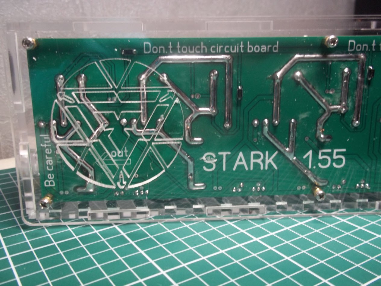
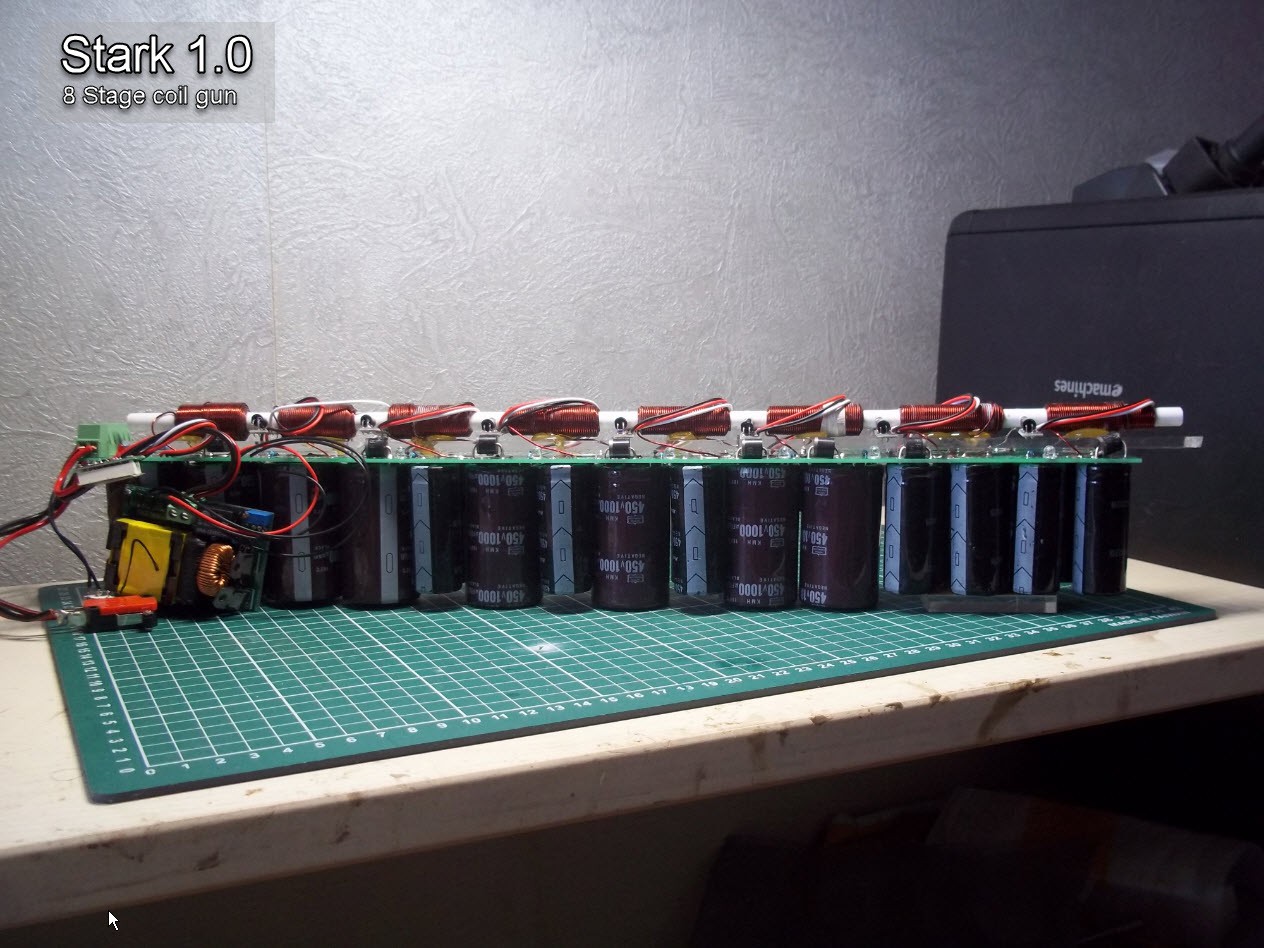
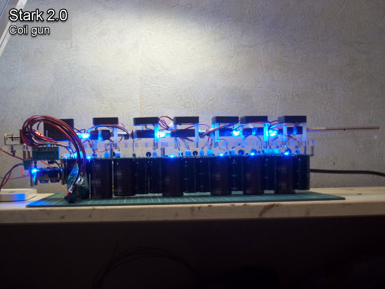
This said, here is a view of my coil gun.
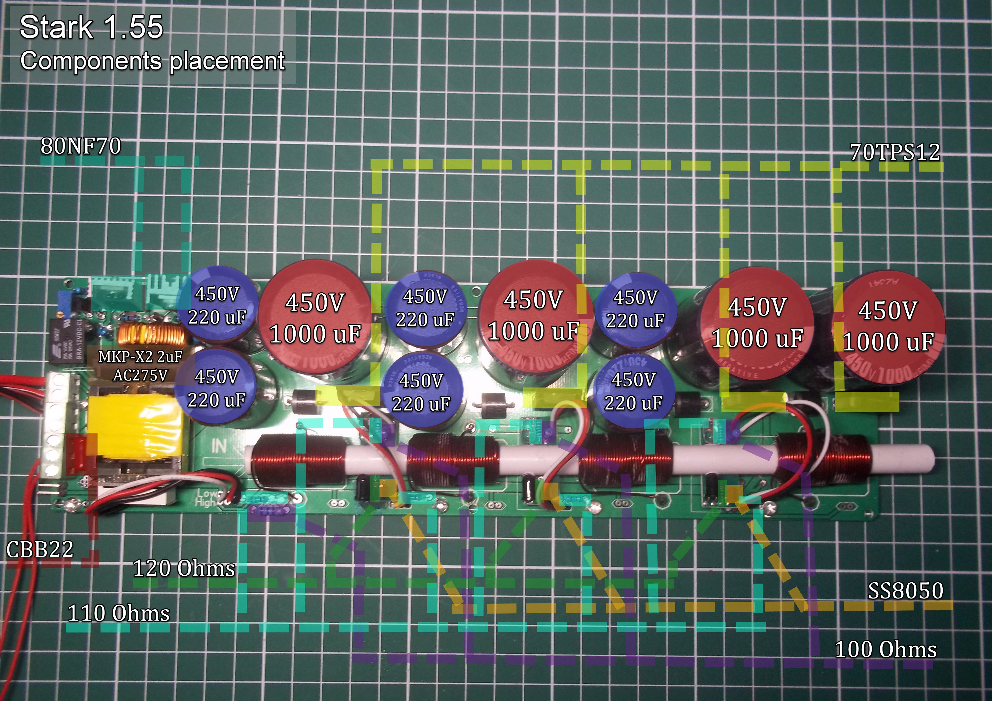
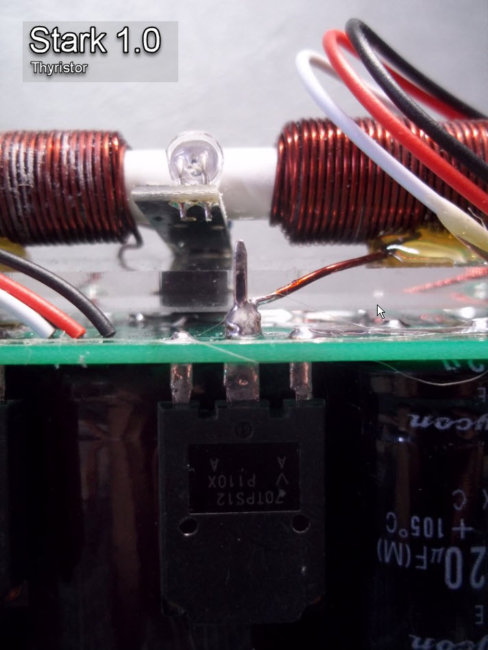
Let's explain the above image, and how everything work.
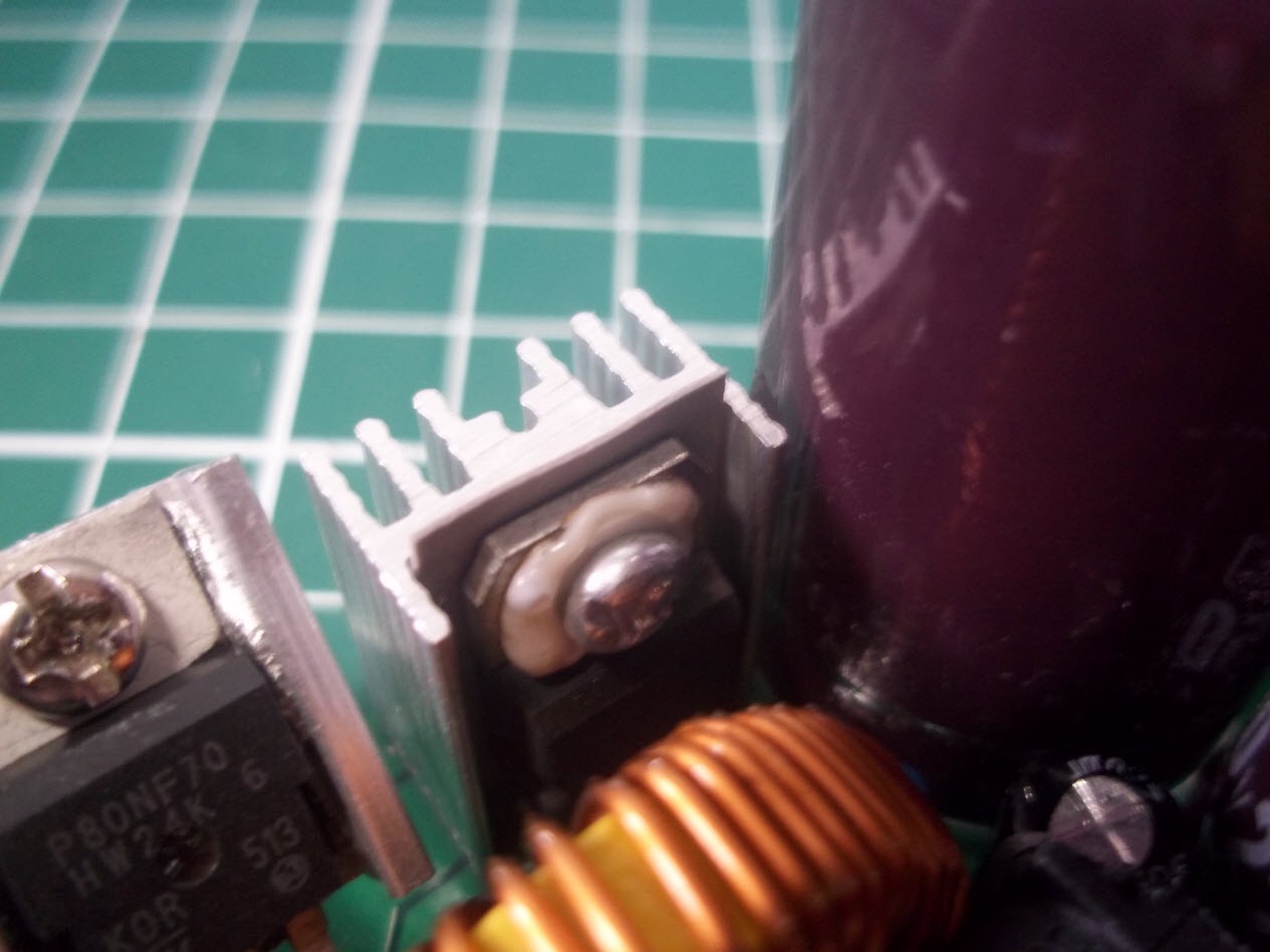
70TPS12: Thyristor, 70A rated - this is device something like combination of diode and transistor. (diode with gate) normal diode turn ON when voltage exceeds 0.7v, but thyristor turn ON when voltage exceeds 0.7v and gate signal presents.
We should give signal to gate to turn on the circuit.
Not like transistors, thyristor can be used to switch high voltages and current, so here thyristor is to connect capacitor to coil.
When that happens capacitor energy flow to coil and magnetic field occurs.
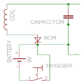
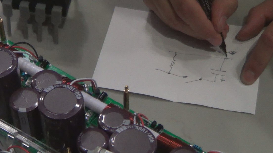
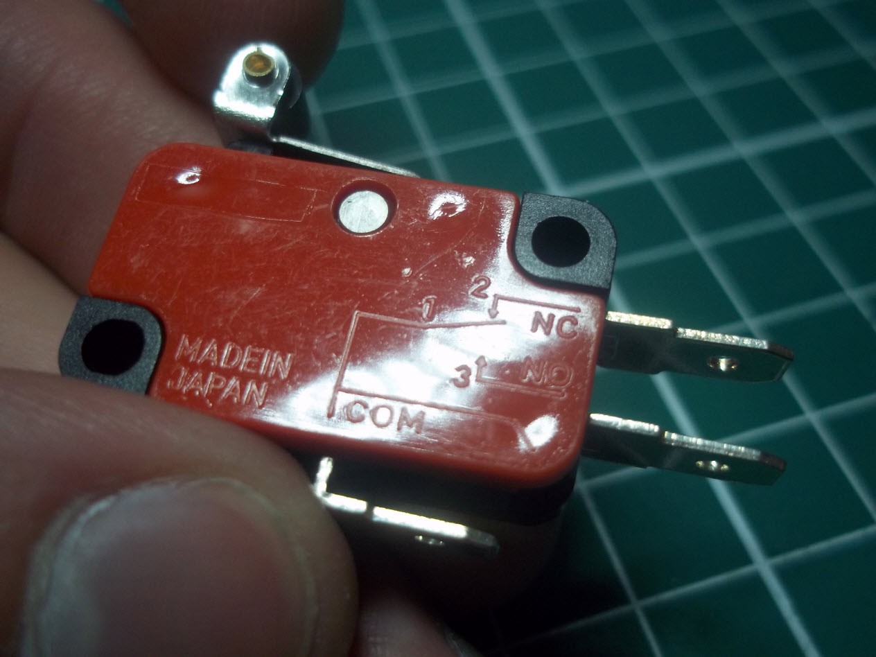
Here SCR is the thyristor, capacitor is charged to high voltage, when trigger switch press, thyristor turns ON and conduct.
Picture took from https://hackaday.io/project/2061 (have a look at his project, this guy did also neat work)
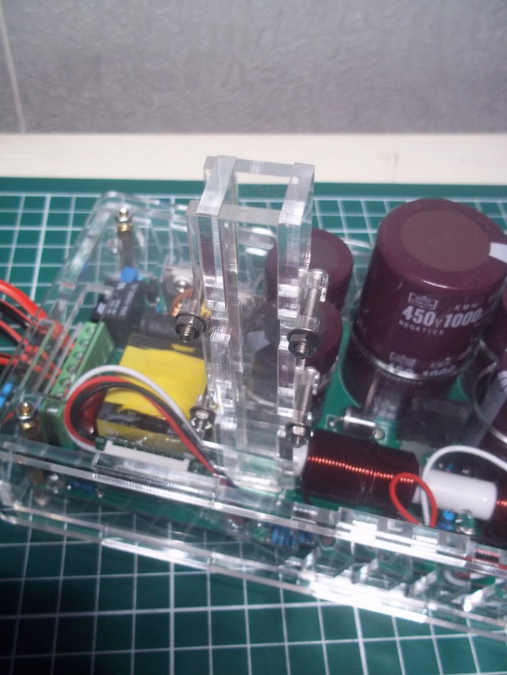
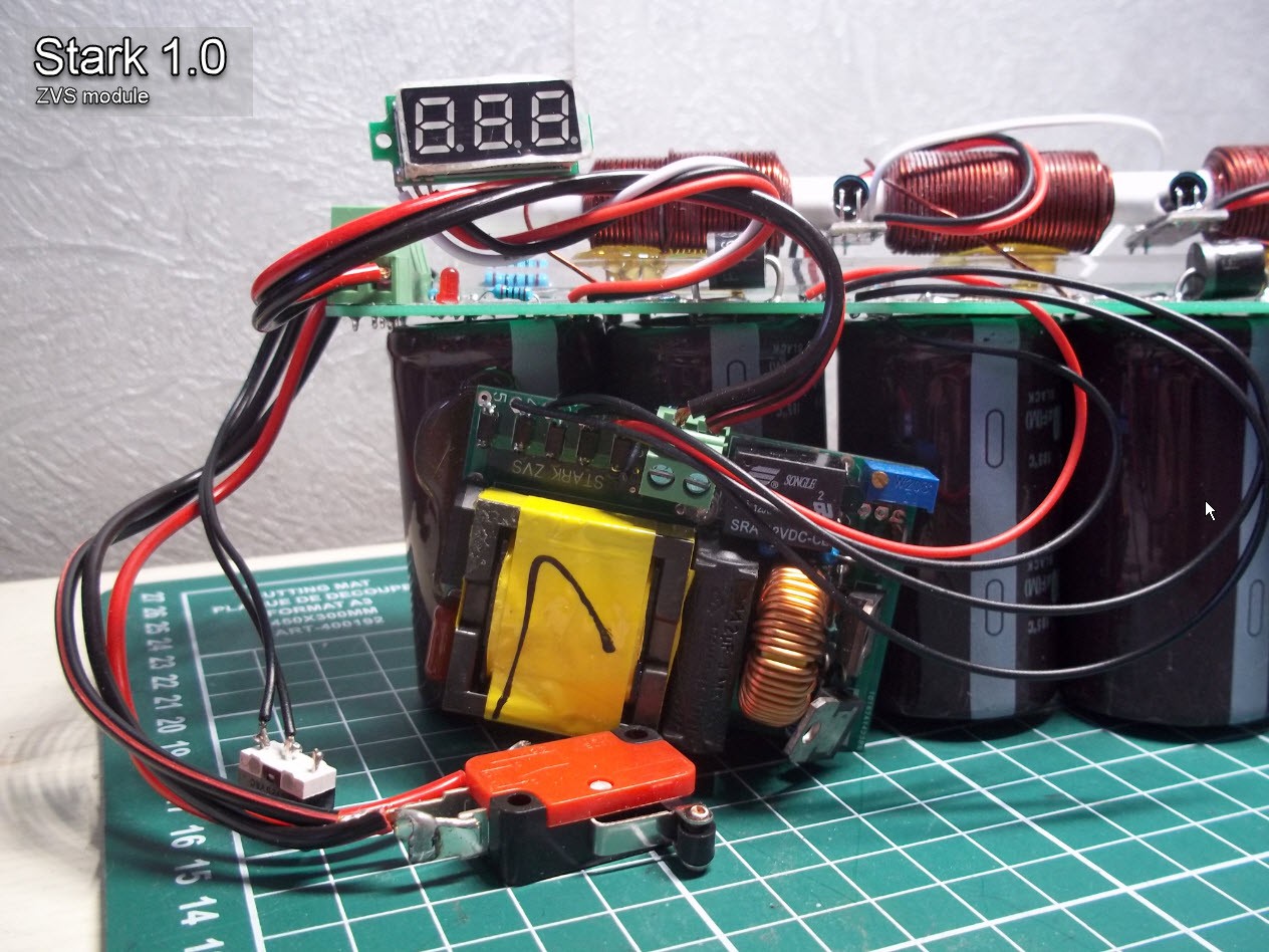
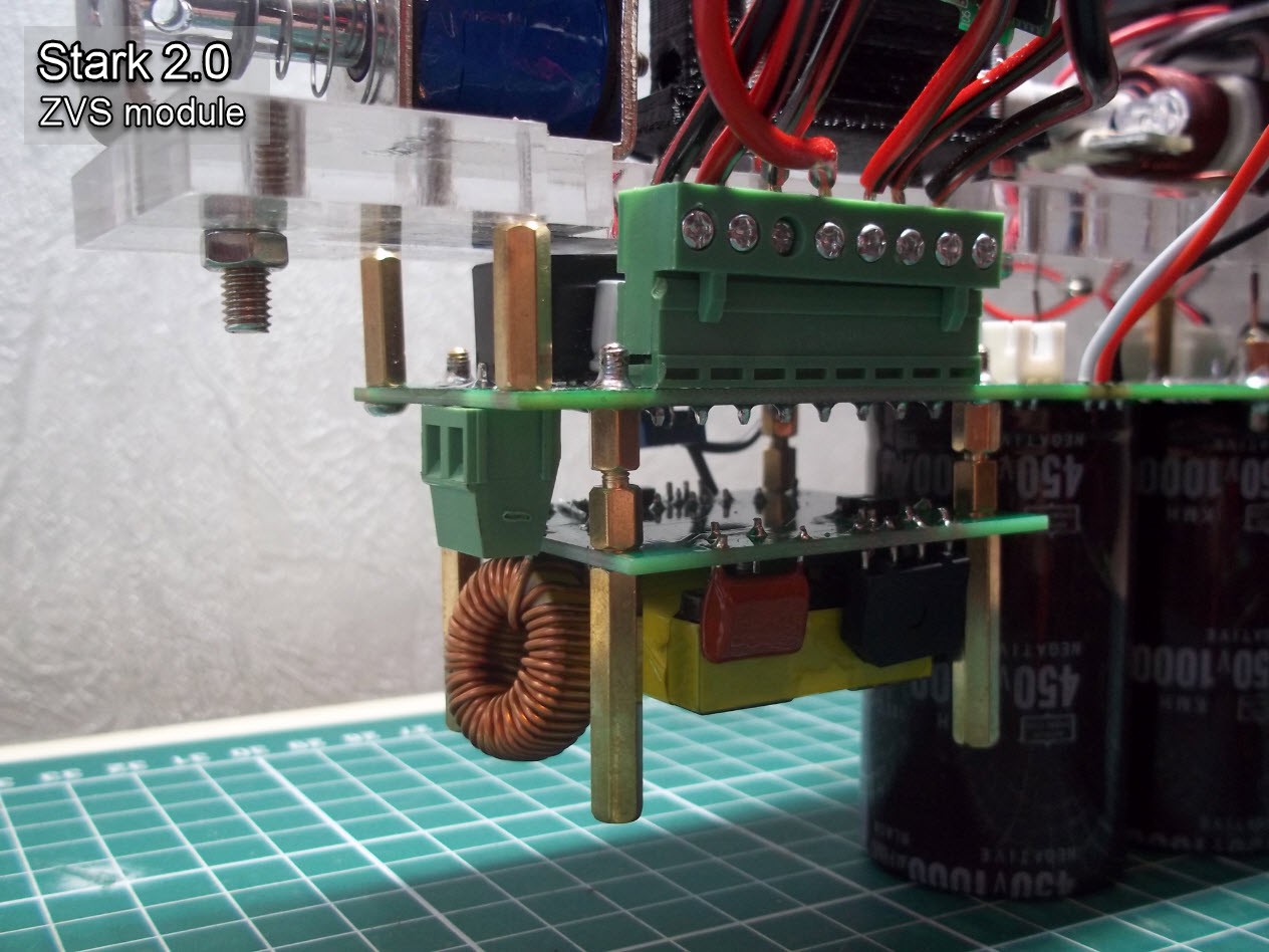
DC-DC boost module (ZVS):
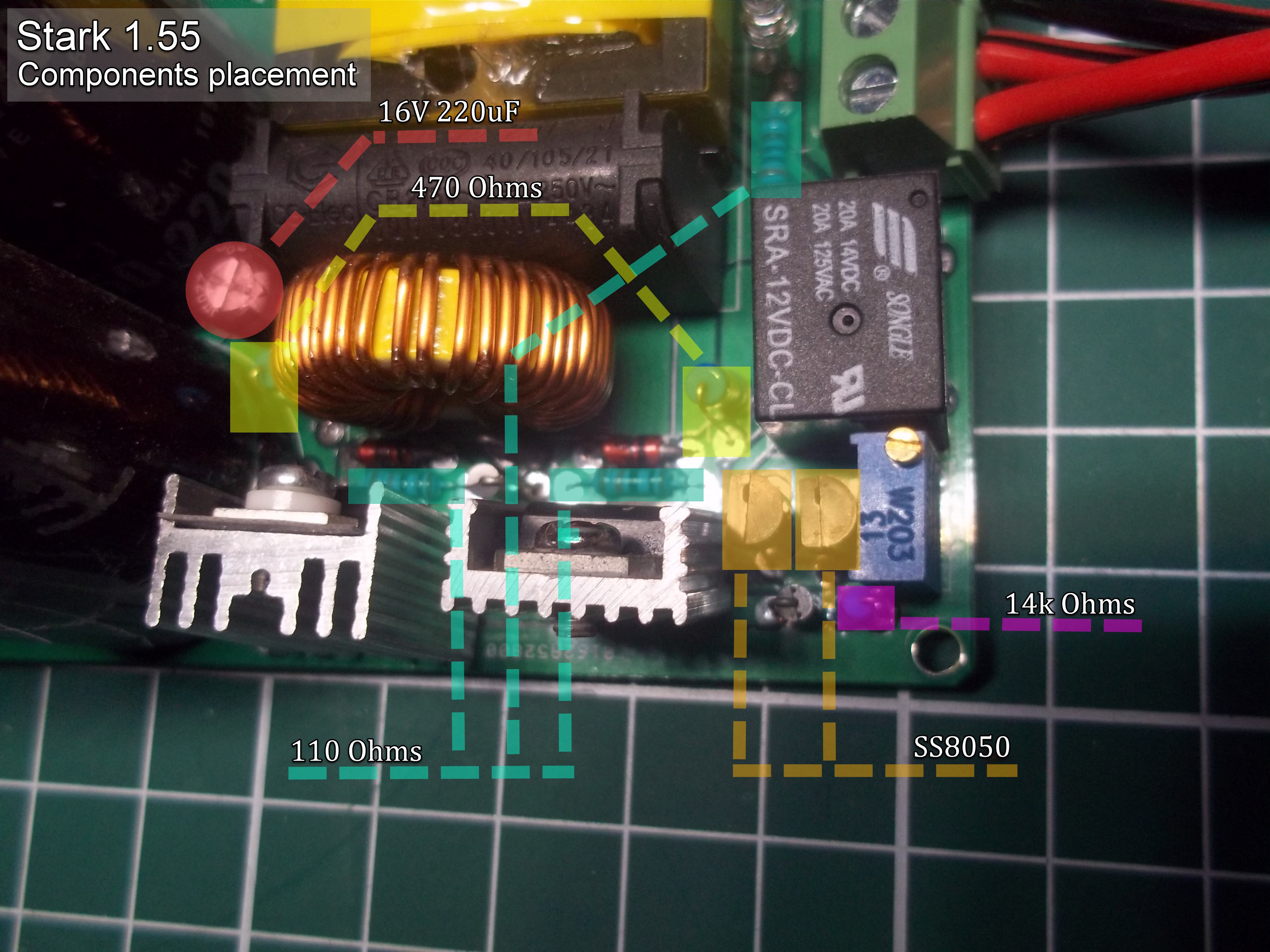
The 7 segment display is a mini 3-wire voltmeter and the pulse transformer is know as ZVS, with a 675W power supply, charging time is one second.
 Coil gun animation by ZeroOne.
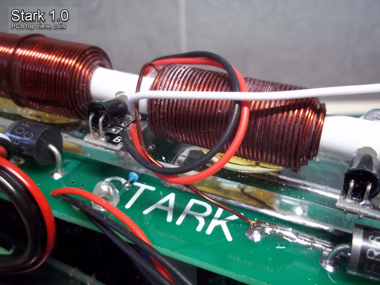
Diodes are in parrallel with coil but reverse direction. that will provide path to coil curent when it power off.
When coil current stop suddenly there occur very high voltage in reverse direction, so if we don't use diode that may cause to damage the circuit (it is a theory about inductors.. we can't stop current in a inductor suddenly, it will cause to have high voltage).
Diode are 6A10 and FR607 with 2 her308.
Keep in mind that if you are going to switch off inductor suddenly, you can't do it. if you do it quickly there will be a spark due to induced high voltage.
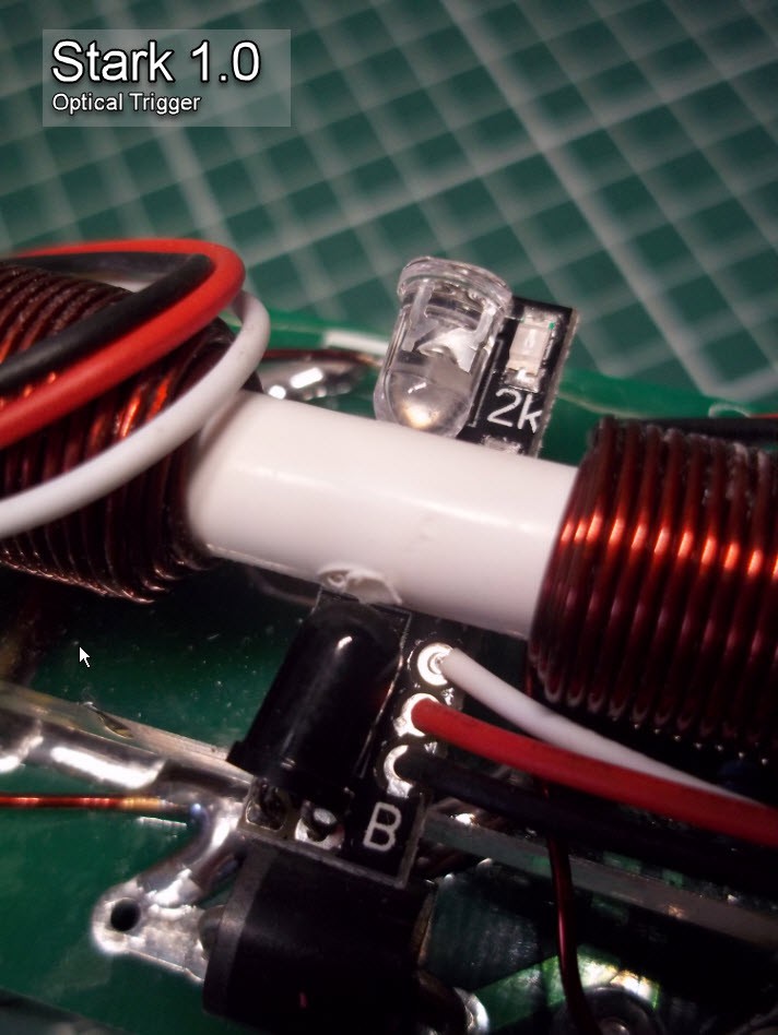
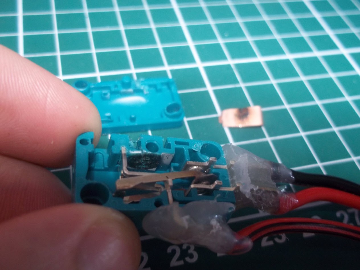
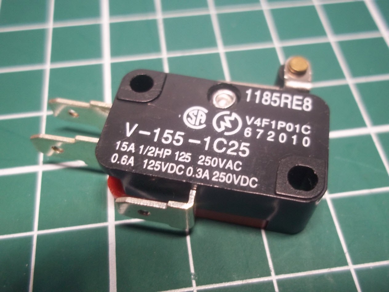
Optical trigger is used to turn off the coil when the projectile is detected.
Infront of IR led (white led) there is IR receiver (black LED)
So when projectile reach there, system detects. Then you can see a transistor, that transistor will amplifiy that signal and send signal to SCR (thyristor) so thyristor get activates.
You can see Transistor very closer to the receiver.
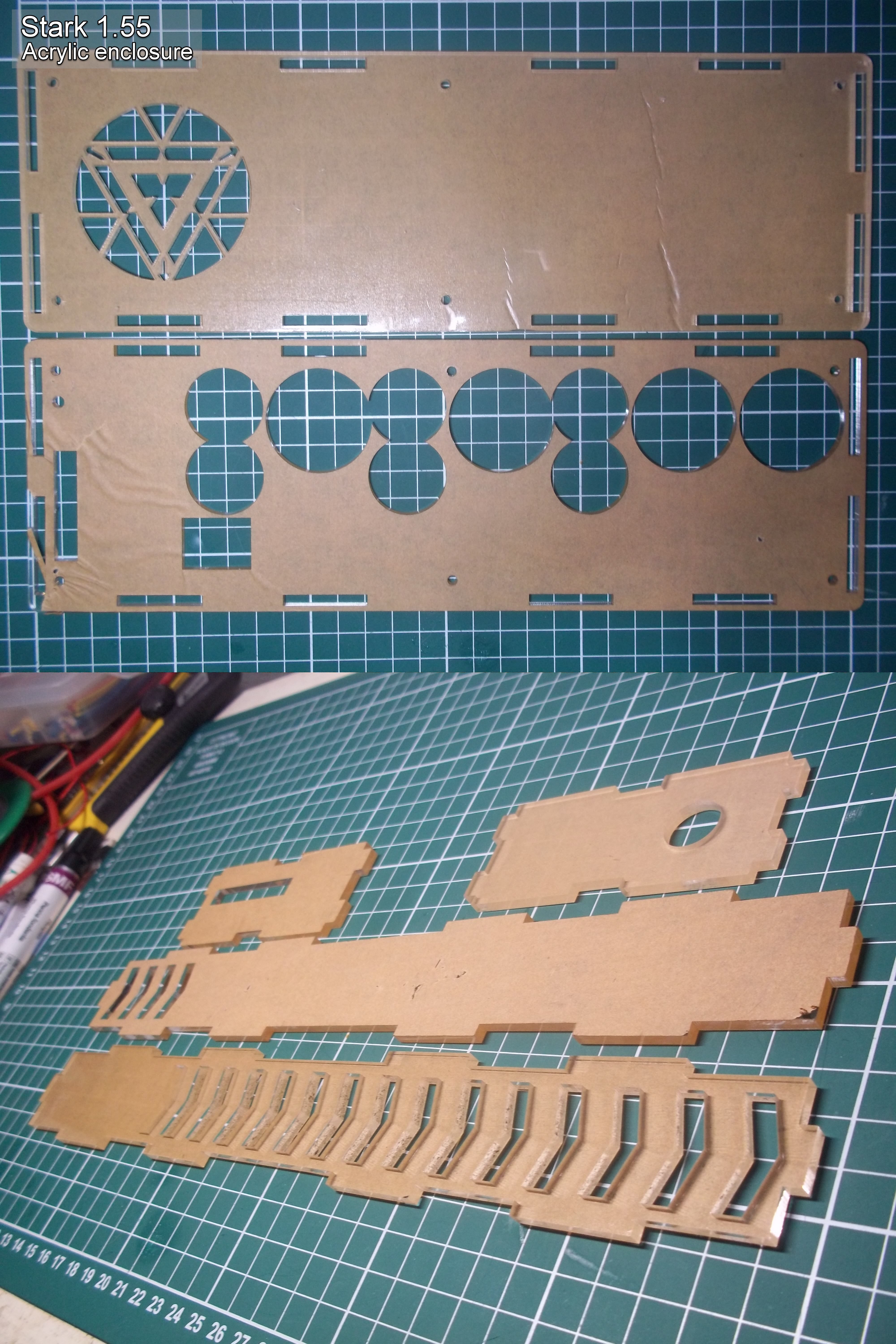
Coils are done with a tool. (this is just for esthetic appeal) We made composed of 3 parts, shaft with end stop, one ring to fit inside and a gauge to know where to stop our winding.
Second fence on the ring is here to 'lock' the begining of magnet wire, we just have to insert it and block it with a finger, then start winding by turning our magnet wire on the shaft.
During the winding process a mini dose of cyanoacrylate is applied on the layer to keep the wires 'blocked' and to have a 'good looking' coil.
When done, we just have to pull the ring out of the shaft to pull also the coil. and reinsert it on our PVC pipe.
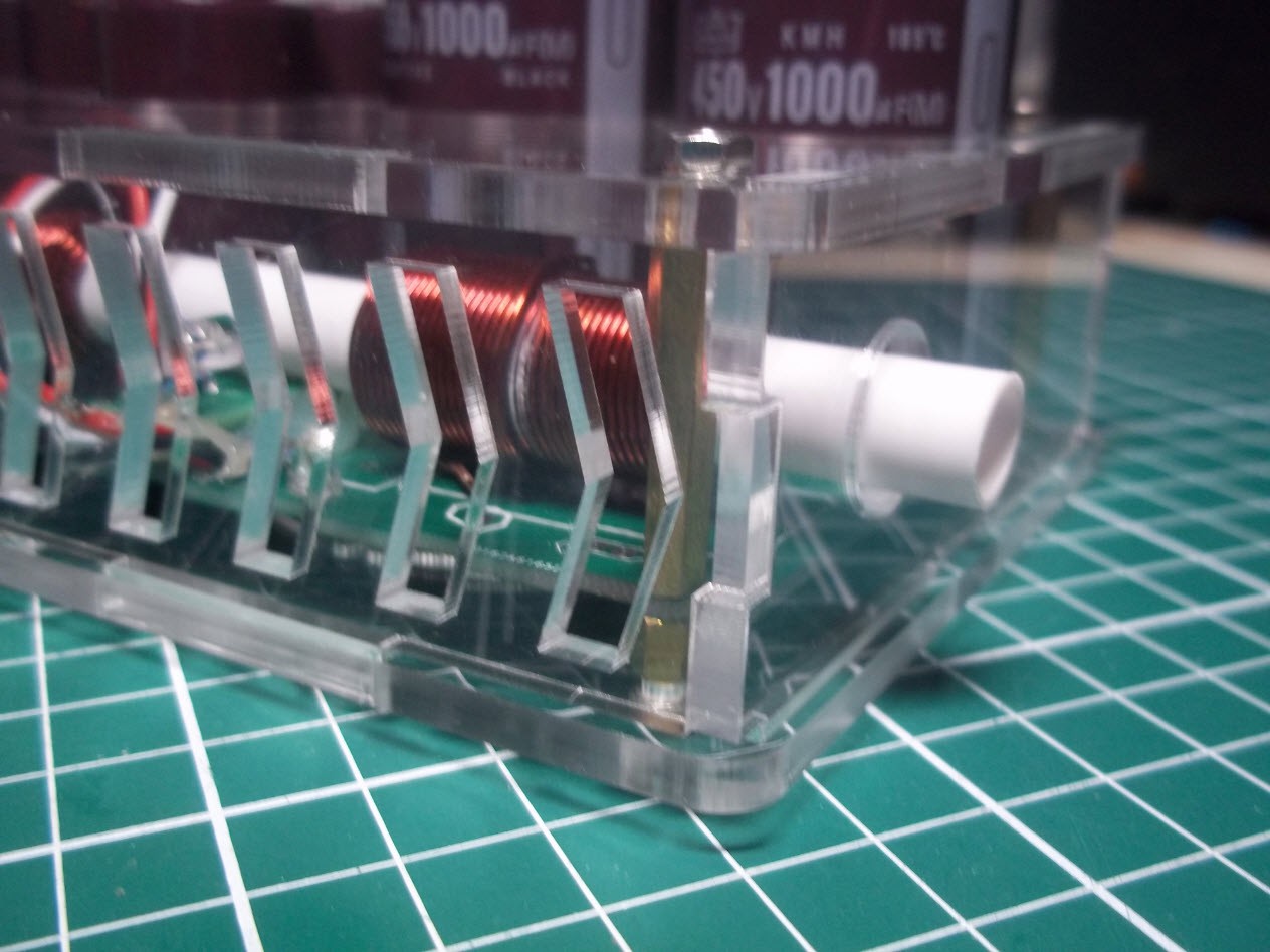
Last pics presenting the rest.
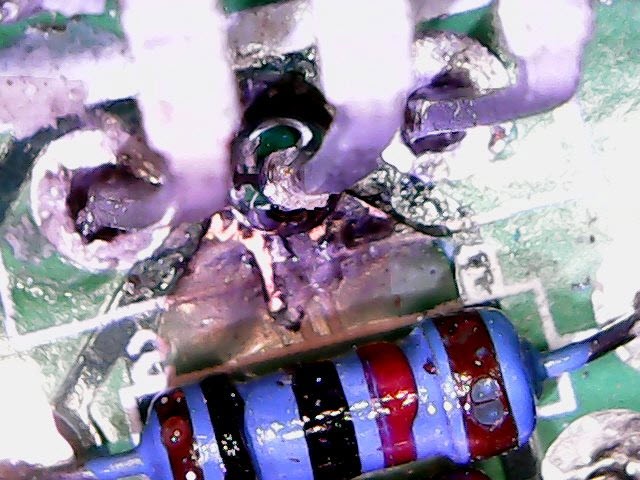
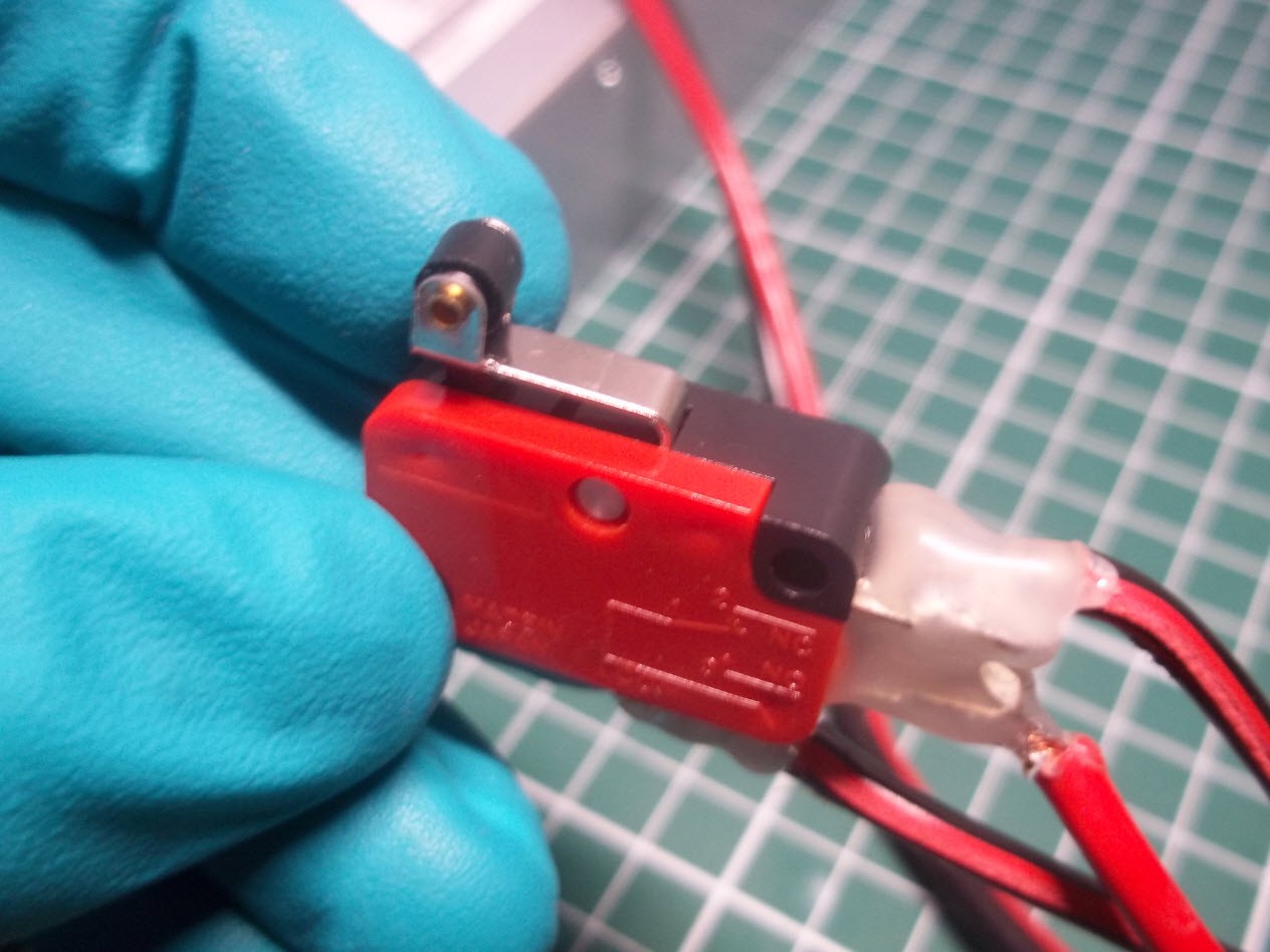
High current paths are soldered to increase capability.
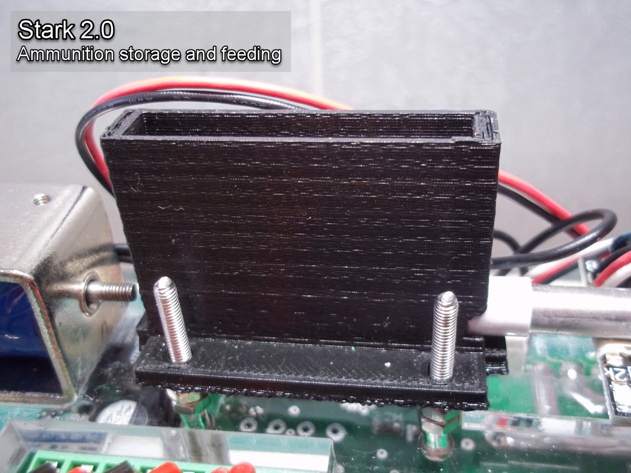
Continuous firing via shell design:
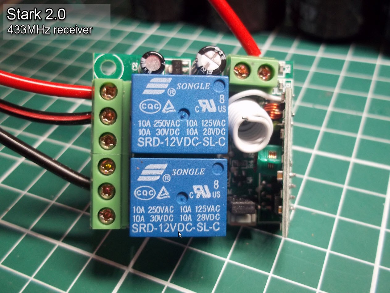
Connections:


 Dominik Meffert
 sky-guided
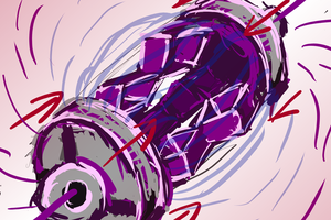
 CapitanVeshdoki
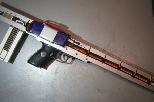
 Pinomelean
This is extra ordinary you can click on the link CCI Ammunition Blazer Aluminum .45 Colt and buy these ammos a=online from the store.