 Christoph
-
Adding a Teensy; I²C Test
11/02/2014 at 20:22 • 0 commentsScrew the UART, I tried I²C first.
Preparing the Teensy
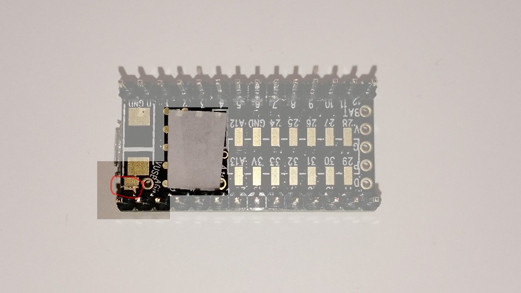
There are some things I stumpled upon, beginning with the pogo pin mounted on the Pi-duino board that's supposed to touch the reset pad on the Teensy's bottom side. It doesn't point straight up:
![]()
So I decided to cover that area of the Teensy to prevent shorts. While I'm dealing with that side I can also cut the Teensy's VUsb trace, because I don't want all those power supplies to fight each other.
![]()
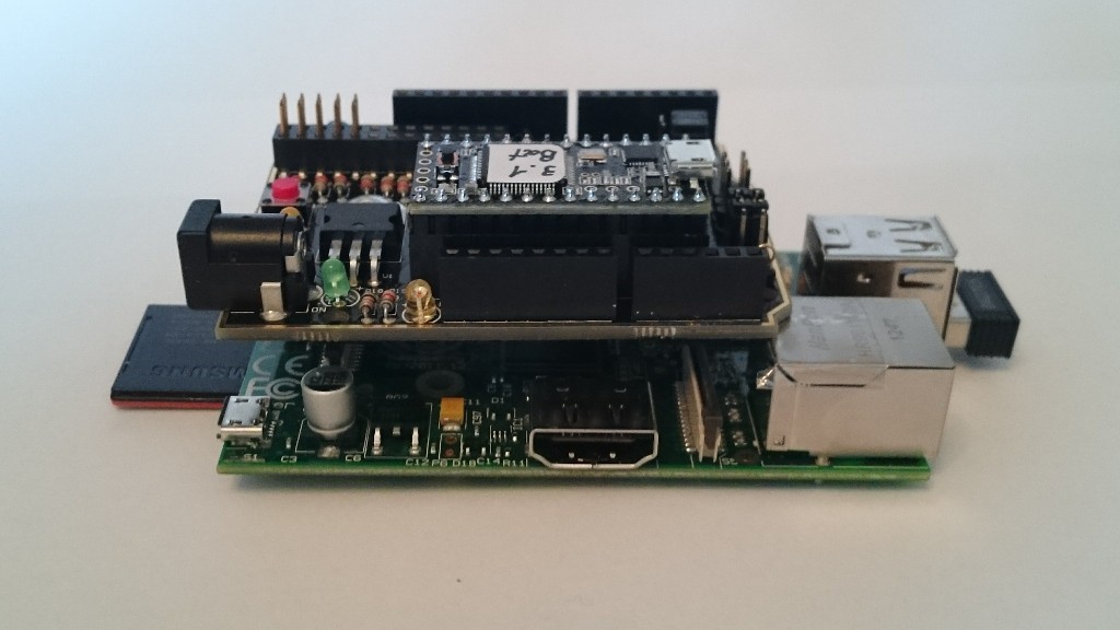
Now we can stack all of them:
![]()
Configuring the board
The board has a configuration header for the I2C connections, H3:
![]() H3 is used to connect either the Teensy or the RPi with the arduino headers. Too bad I want to connect the Pi with the Teensy, but there's a workaround. I configured the header for Teensy <-> arduino, and then used two jumper cables to connect RPi <-> arduino:
H3 is used to connect either the Teensy or the RPi with the arduino headers. Too bad I want to connect the Pi with the Teensy, but there's a workaround. I configured the header for Teensy <-> arduino, and then used two jumper cables to connect RPi <-> arduino:![]()
There's a very cool I2C library for the Teensy 3.x that I use (find it at http://forum.pjrc.com/threads/21680-New-I2C-library-for-Teensy3) and it comes with a slave example sketch. I uploaded that to the Teensy and ran
i2cdetect -y 1on the Pi and the device was detected:
     0  1  2  3  4  5  6  7  8  9  a  b  c  d  e  f
00:          -- -- -- -- -- -- -- -- -- -- -- -- --
10: -- -- -- -- -- -- -- -- -- -- -- -- -- -- -- --
20: -- -- -- -- -- -- -- -- -- -- -- -- -- -- -- --
30: -- -- -- -- -- -- -- -- -- -- -- -- -- -- -- --
40: -- -- -- -- 44 -- -- -- -- -- -- -- -- -- -- --
50: -- -- -- -- -- -- -- -- -- -- -- -- -- -- -- --
60: -- -- -- -- -- -- -- -- -- -- -- -- -- -- -- --
very good! I can now adapt it to actually turn received data into servo pulses.
-
A first look at the board
10/31/2014 at 13:13 • 0 commentsWell the board was delayed a bit in customs, and then by me because I had more important things to do, unfortunately.
Top:
![]() There are a few familiar headers I'd like to start with:
There are a few familiar headers I'd like to start with:- At the top left corner there's the Pi's GPIO header,
- then, along the top edge, one row of arduino headers
- the second row of arduino headers is at the bottom edge
- and finally the two rows or Teensy 3 headers.
Additionally, the board comes with
- the yellow header (YH1, top right) for jumpers that connect between the Teensy UART1 and the RPi's UART (pins 8 and 10 of the Pi's GPIO)
- H2, which has the Teensy's SPI pins (11, 12 and 13), Reset, and power,
- and H3 for jumpers that connect either the Pi or the Teensy to the I²C signals on the arduino headers.
There's also a pogo pin that is supposed to hit the Teensy's reset signal at a test point that is located on the bottom side of the Teensy. I don't really believe that as I've already touched it and it looks a bit slanted.
Also, no silk screen hint about which way the teensy goes in, I had to grab the schematic to find out. And I measured the supply pin voltages to be sure.
Bottom:
![]()
How nice! Foam strips to protect the display and camera connectors! Not much more to say about the bottom side (for now).
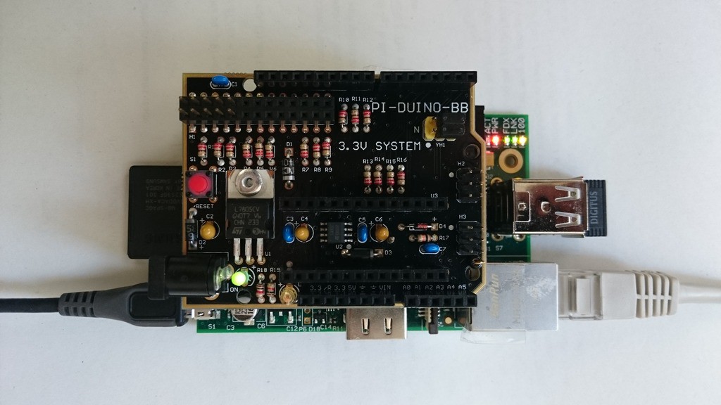
Stacked with the Pi:
![]()
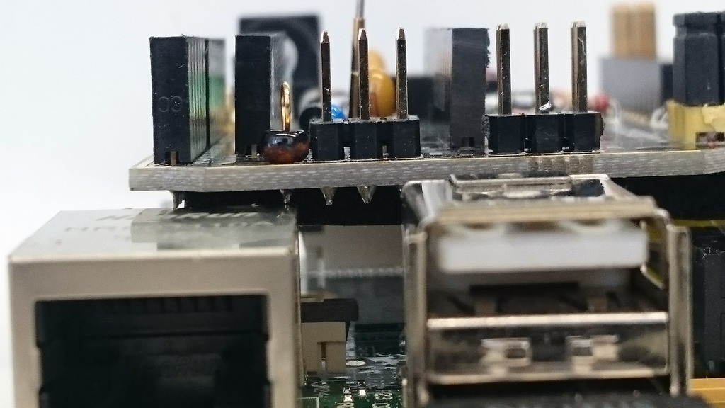
The board overlaps the LAN and video jacks. That's not a problem right away, but let's take a closer look:
![]()
Yup, the pin touches the jack. I don't know what the "bead"-thingy is, but this will surely benefit from a piece of tape. The same for the video jack:
![]()
with tape already applied. After that was done I powered the combo up and there was no smoke:
![]()
I'll plug in a Teensy next time and try to talk to it via serial (PC -> Pi -> Teensy (echo sketch) -> Pi -> PC).
-
That's better...
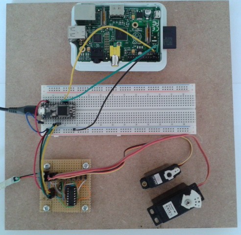
05/31/2014 at 10:17 • 0 commentsI mounted the Pi, a breadboard with the Teensy 3.0, and the HC164 board on a piece of MDF. Less loose wires, no USB cables pushing around my boards, and a way of moving the whole thing at once:
![]()
-
Tested Teensy 3.0 with I²C interface and servo driver
05/29/2014 at 18:12 • 0 commentsI soldered the HC164 board:
![]() And tested it with simple code that simply sets the servo outputs to a fixed value. Here's the hardware:
And tested it with simple code that simply sets the servo outputs to a fixed value. Here's the hardware:![]()
The HC164 is powered with 3.3 V from the Teensy, which worked well.
Then I added a simple I²C slave interface and tested that with a Bus Pirate:
![]() I used the Bus Pirate's on-board pull-ups with VPullup connected to the Teensy's 3.3 V output. It's been the first time I used that feature and it worked flawlessly.
I used the Bus Pirate's on-board pull-ups with VPullup connected to the Teensy's 3.3 V output. It's been the first time I used that feature and it worked flawlessly.The next step is to connect this setup to a Raspberry Pi and write code that sends servo positions over I²C. When that works, all I need is the Pi-Duino-Teensy board to put all of this together.
-
Laid out shift register board
05/28/2014 at 21:04 • 0 commentsI laid out the shfit register (74HC164) board:
![]() Two screw terminals for the servo supply, female header for the Teensy connection (3.3 V, Frame, Tx and Gnd) with optional screw terminals, decoupling cap (not labeled), and a jumper to choose the supply for the shift register (it can be powered by the servo supply or by the teensy).
Two screw terminals for the servo supply, female header for the Teensy connection (3.3 V, Frame, Tx and Gnd) with optional screw terminals, decoupling cap (not labeled), and a jumper to choose the supply for the shift register (it can be powered by the servo supply or by the teensy). -
Powering the shift register, logic levels
05/27/2014 at 13:35 • 0 commentsI'm now figuring out what voltage to use to power the shift register.
Powering it from 5 V doesn't sound promising, as the HC164's minimum input high voltage is somewhere above 3.15 V. The Teensy, however, being a 3.3 V device, will output a high level somewhere around 2.8 V.
Powering it from 3.3 V would surely work on the Teensy side, but I'm not sure if the servos would be happy about a 2.8 V input high level (or something like that). I guess I'll have to test that...
-
Prepared the Pi
05/27/2014 at 11:01 • 0 commentsI downloaded the latest raspbian (that's 2014-01-07-wheezy-raspbian), dumped it on an SD card and the pi was running immediately. Also configured the I²C bus following the adafruit description. After attaching a PCF8574A to the bus, I could successfully detect it with
sudo i2cdetect -y 1
Resulting in
     0  1  2  3  4  5  6  7  8  9  a  b  c  d  e  f
00:          -- -- -- -- -- -- -- -- -- -- -- -- --
10: -- -- -- -- -- -- -- -- -- -- -- -- -- -- -- --
20: -- -- -- -- -- -- -- -- -- -- -- -- -- -- -- --
30: -- -- -- -- -- -- -- -- -- -- -- -- -- -- -- 3f
40: -- -- -- -- -- -- -- -- -- -- -- -- -- -- -- --
50: -- -- -- -- -- -- -- -- -- -- -- -- -- -- -- --
60: -- -- -- -- -- -- -- -- -- -- -- -- -- -- -- --
0x3F is the PCF8574A's address if A0..A2 are tied high (which they were in my test). Fine.
I can now build the servo board that connects to the teensy 3.1.
-
Power
05/26/2014 at 23:17 • 0 commentsThe teensy can be powered externally, and it would be convenient to use the pi to power it. I'll have to take a close look at the schematic to see if that works as I'd like it to. I guess I'll just plug it in and see what happens.
-
Waiting for mail
05/26/2014 at 22:02 • 0 commentsI have a Raspberry Pi, Teensy 3.0 and 3.1, at least two working servos, a shift register and all the stuff I need - apart from the Pi-Duino-Teensy board, which is somewhere between the US and my mail box. Meanwhile, I can write code to use the Teensy 3.1 as an I²C slave, and to generate the PPM signal. Both features are basically provided by teensyduino libraries, so this should be fairly easy.
Pi-Duino-Teensy test with RC servos
I was asked to test the Pi-Duino-Teensy board by a PJRC forum member. I'll use it to control RC servos.

 H3 is used to connect either the Teensy or the RPi with the arduino headers. Too bad I want to connect the Pi with the Teensy, but there's a workaround. I configured the header for Teensy <-> arduino, and then used two jumper cables to connect RPi <-> arduino:
 There are a few familiar headers I'd like to start with:
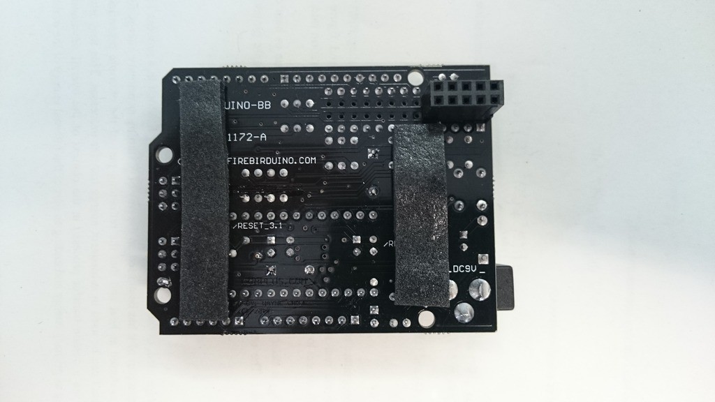


 And tested it with simple code that simply sets the servo outputs to a fixed value. Here's the hardware:
 I used the Bus Pirate's on-board pull-ups with VPullup connected to the Teensy's 3.3 V output. It's been the first time I used that feature and it worked flawlessly.
 Two screw terminals for the servo supply, female header for the Teensy connection (3.3 V, Frame, Tx and Gnd) with optional screw terminals, decoupling cap (not labeled), and a jumper to choose the supply for the shift register (it can be powered by the servo supply or by the teensy).