Close
0%
0%

8x8x8 Blue LED Cube

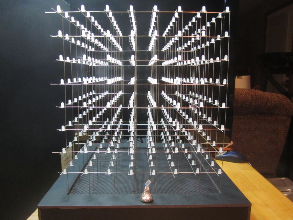
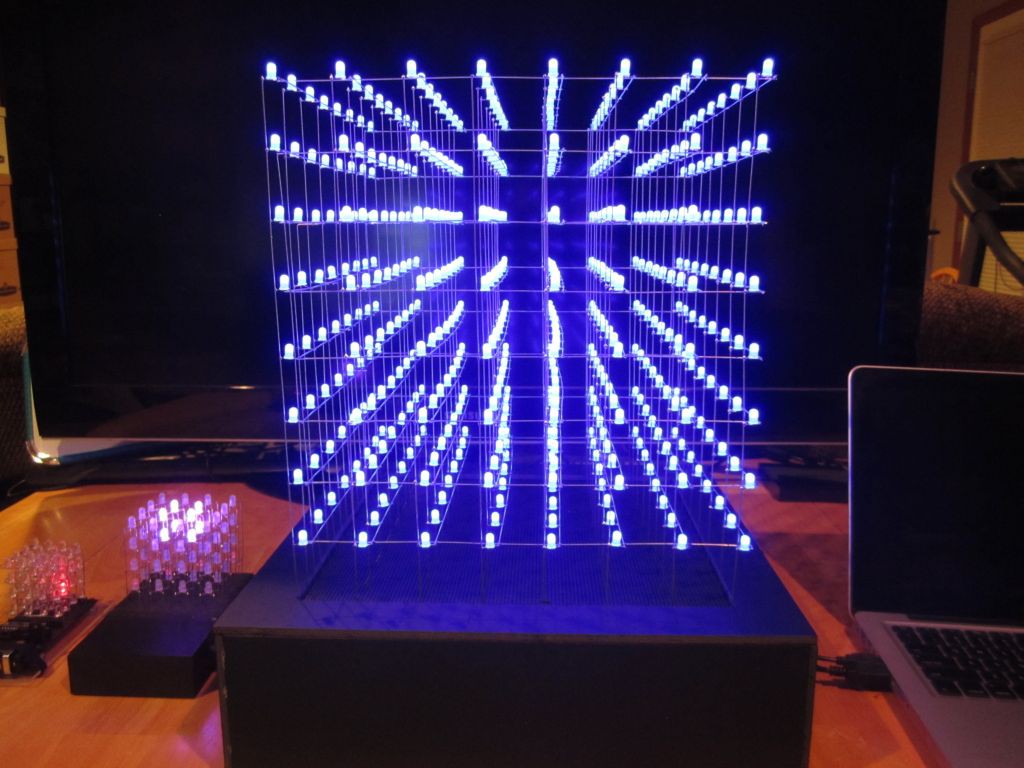
512 LEDs driven by an Arduino via eight shift-registers and eight MOSFETs

Similar projects worth following
512 LEDs driven by an Arduino via eight 8-bit shift registers and eight MOSFETs.
Most LED cubes I've seen are limited by the LED lead length. I wanted my cube to be as large as possible while still producing smooth animations. I settled on 4cm between leds, resulting in a 28 cm (11 inch) cube.

I also wanted the cube to be more interactive, so I used the remaining six ports on the Arduino to handle three touch sensors (thanks to Paul Badger for his awesome CapSense library) and two potentiometers.

Videos of this project:
http://www.youtube.com/playlist?list=PL-xZsBalytNBI9KC3nuA_Jo6j9hP-5_9D

I found the 4x4x4 RGB cube very rewarding to build so I'm moving up to 8x8x8.  I decided that I'm not ready for RGB version yet, so I'm only building single color.

WIRING:
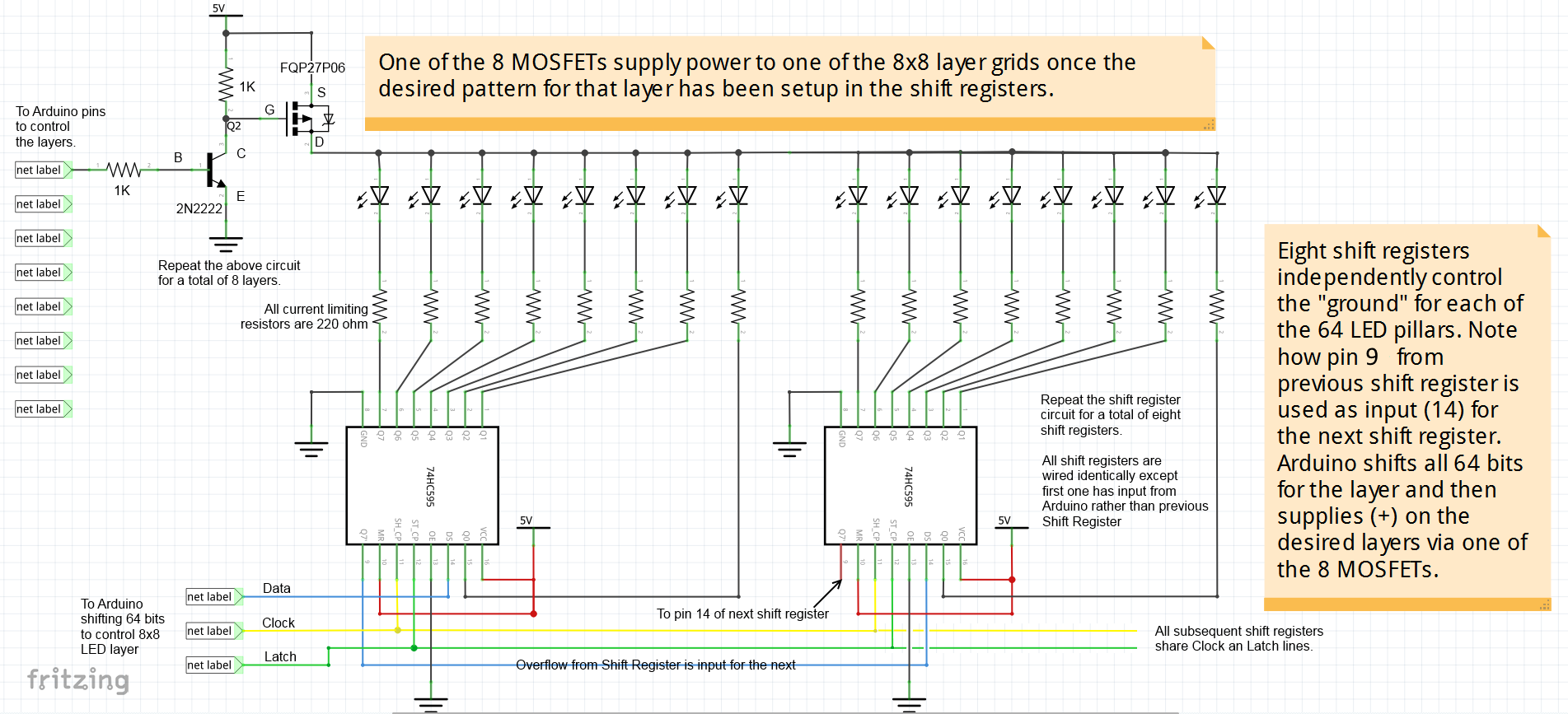
Electrically, the cube is made up of 64 pillars containing 8 LEDs each.
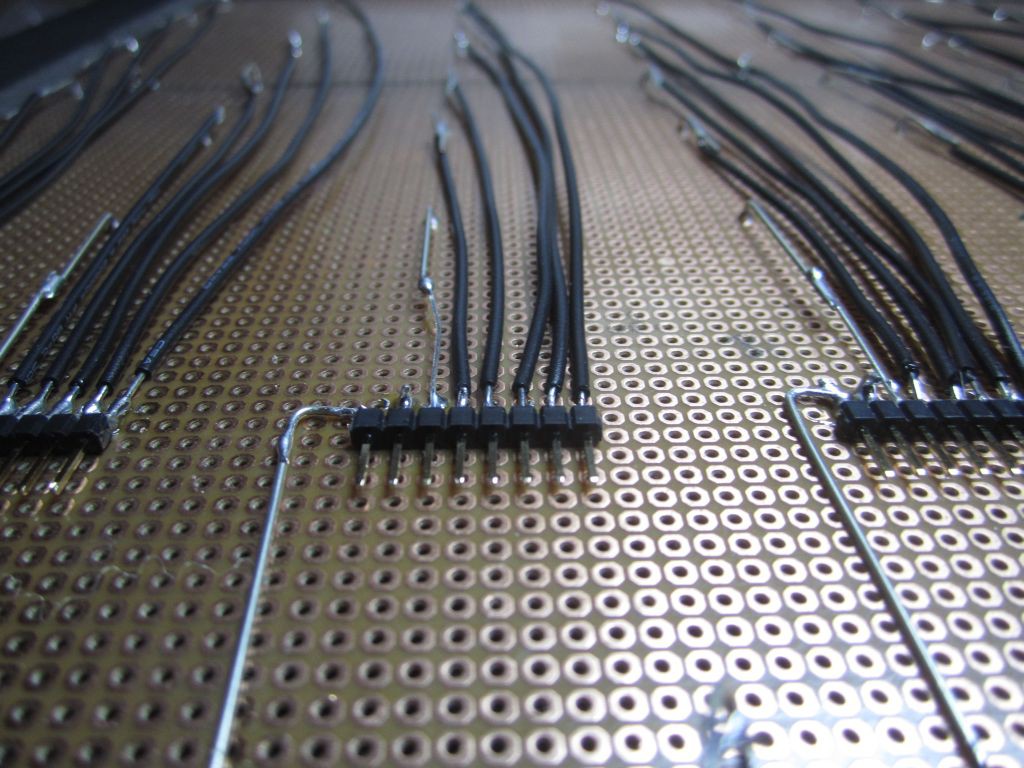
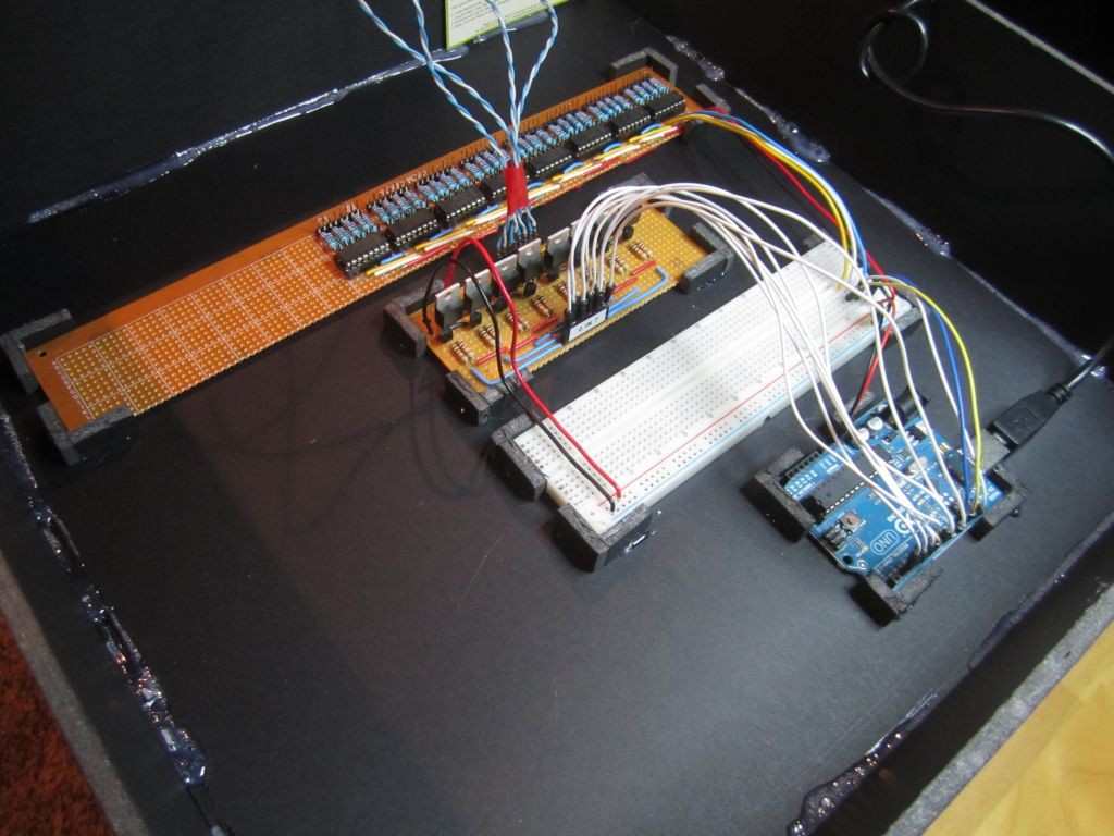
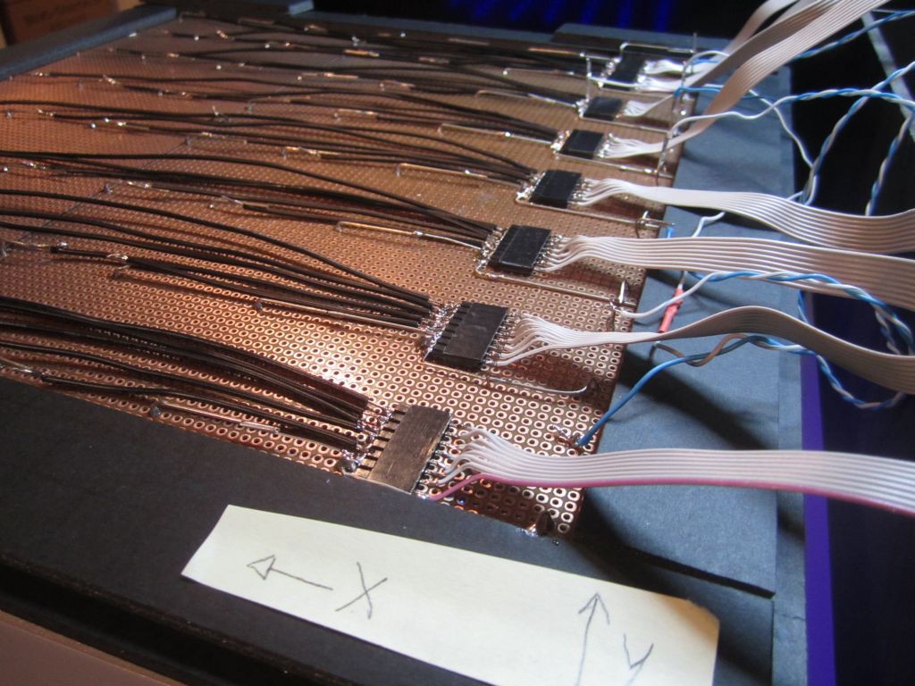
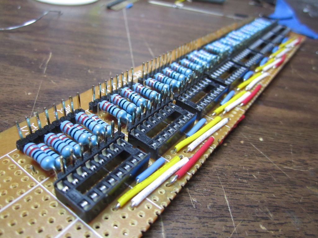
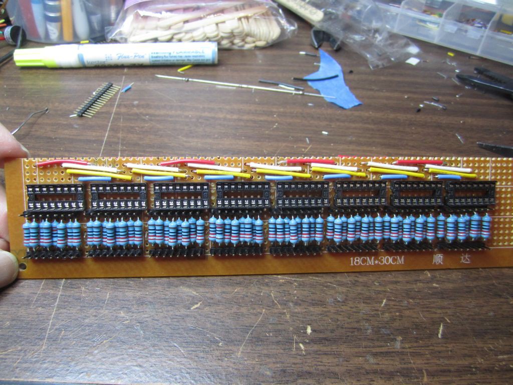
Eight 8-bit shift registers (74HC595) supplies the GROUND for those pillars.

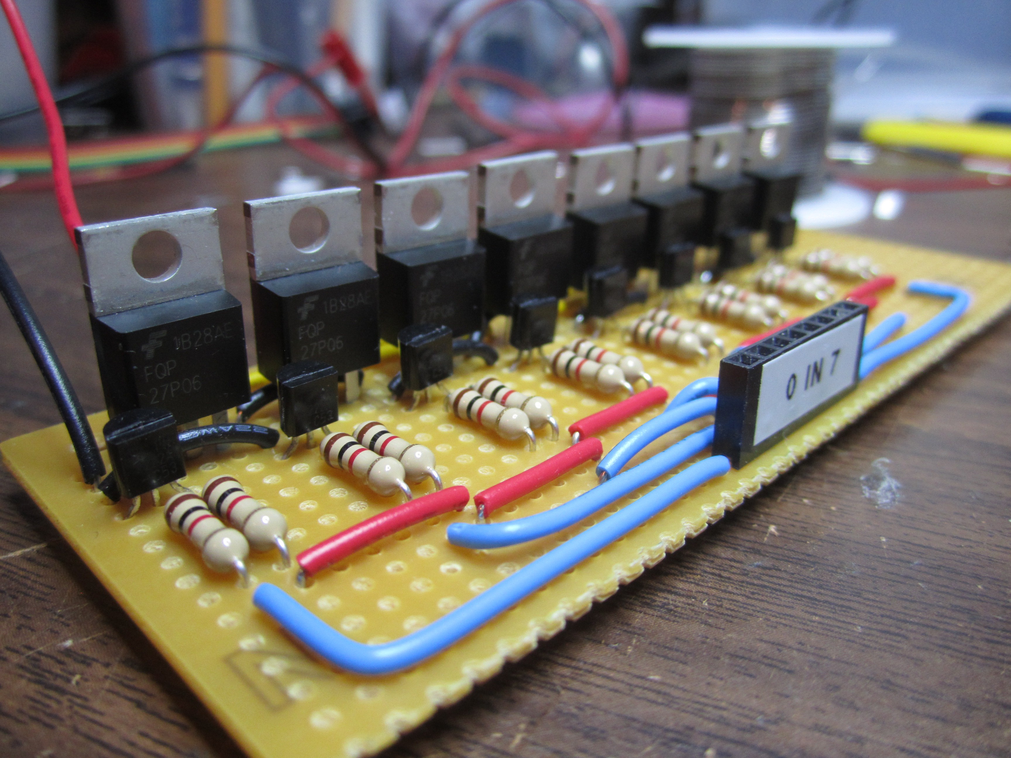
Each layer of the cube shares a common +5V switched by a P-Channel MOSFET, for a total of 8 MOSFETs.

HOW IT WORKS:
At any time, a maximum of 64 LEDs of ONE particular layer would be all lit up. Quickly setting up which of those LEDs on that layer should be on and then repeating that for the other layers, gives the illusion that we can individually control every individual LED.

LESSONS LEARNED:
My desire to spread the LEDs beyond the length of the LED leads added a LOT of complexity to the cube construction.  More soldering, having to deal with alignment of the extra wires.  Larger cube also meant more fragile cube.  The result is an impressive 11"x11"x11" cube.  However, it took many more hours to build compared to the usual led cube.

I made a mistake in wiring the ground of the shift register to the AREF pin of the Arduino instead of GND.  This resulted a lot of unnecessary circuit, which I was later able to eliminate.  The final circuit uses a 2N2222A NPN-Transistor and a FQP27P06 P-Channel MOSFET for each layer, and no extra transistors for the shift registers.

CODE:

Various versions of the code is on github

View all 14 components

  • Circuit Diagram

    Hari Wiguna12/05/2014 at 01:16 1 comment

    Click to see larger version.

  • Added Touch Sensors

    Hari Wiguna07/26/2014 at 13:30 0 comments

  • It's done!

    Hari Wiguna07/24/2014 at 23:47 0 comments

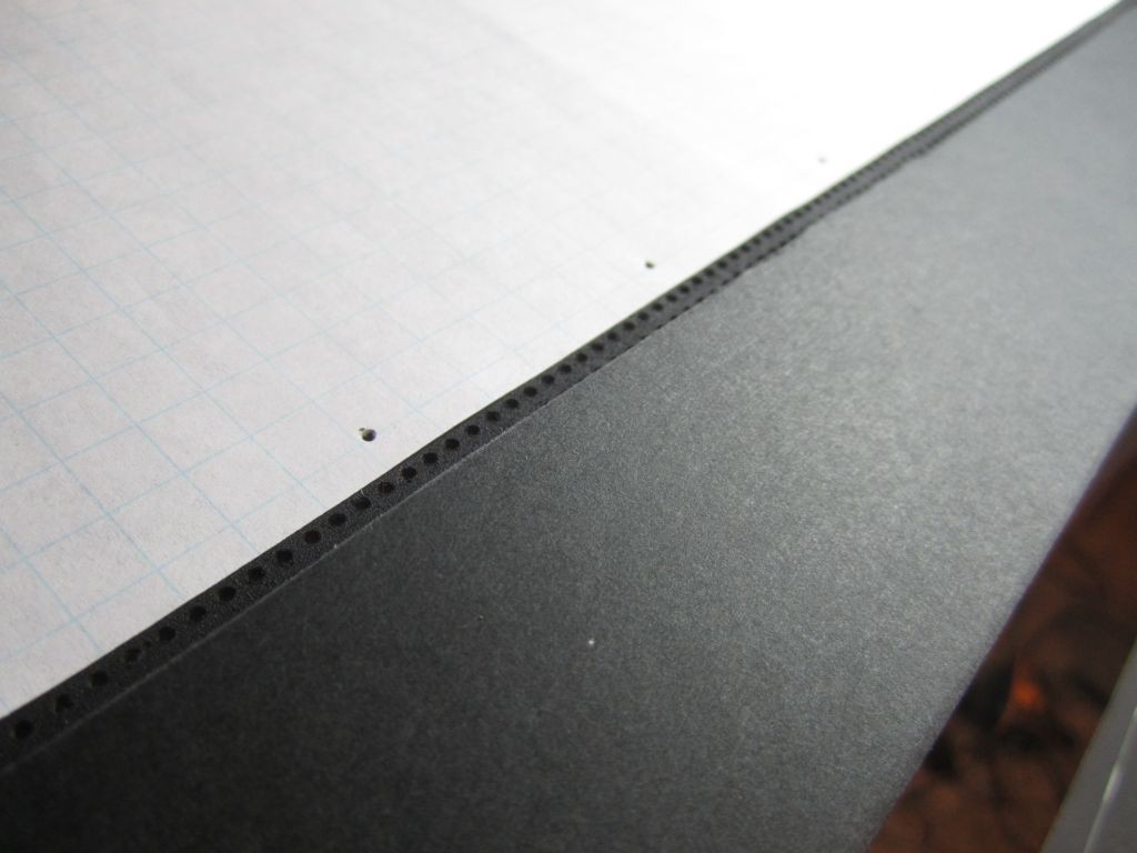
    Instead of counting holes on the PCB, I used a piece of paper as a jig.

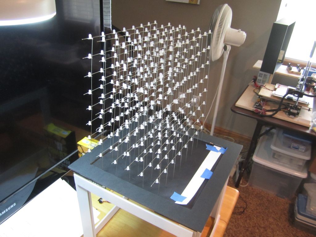
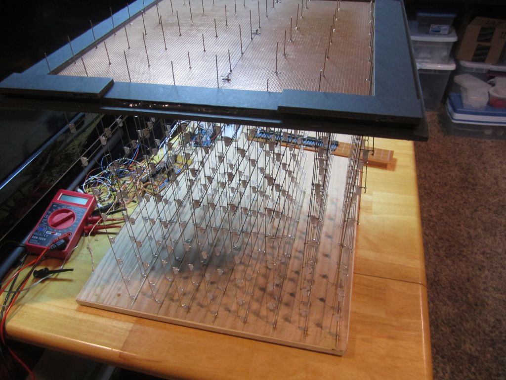
    All the top LEDs are rested in the holes of the wooden jig.  It was standing like this while I solder all the cross wires.

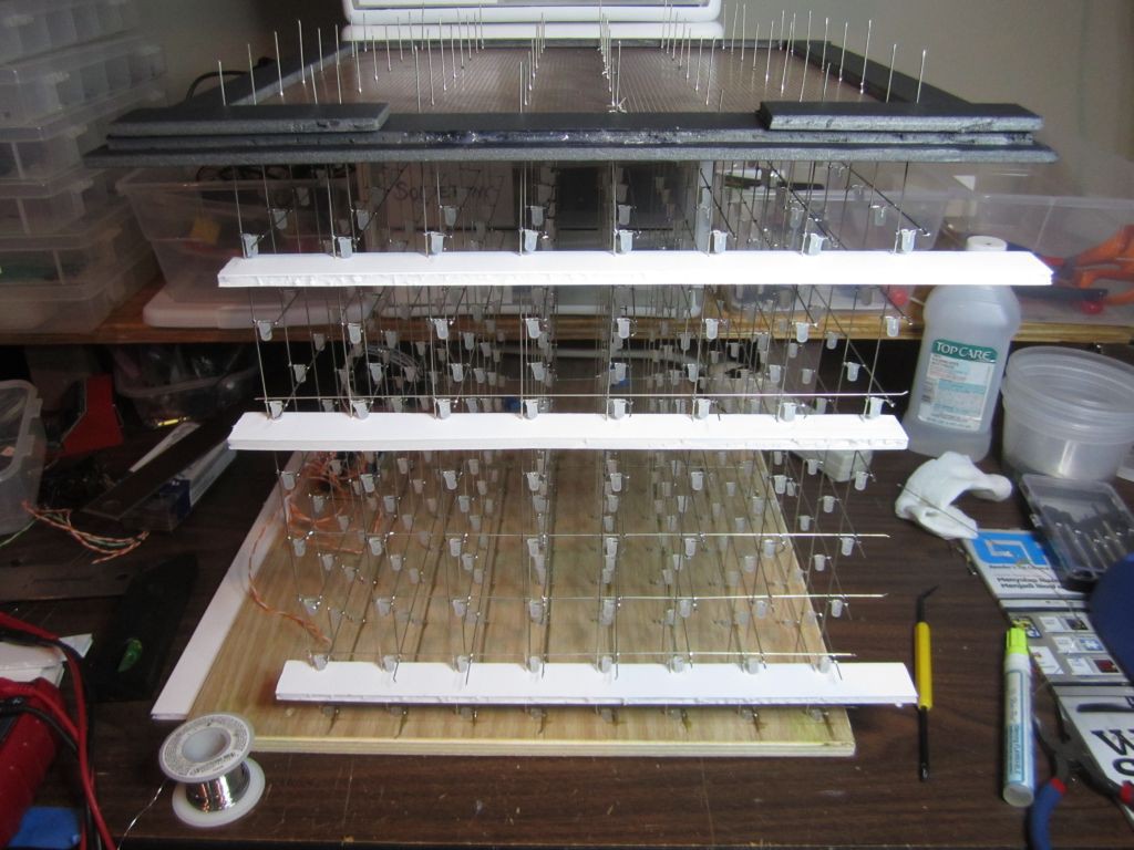
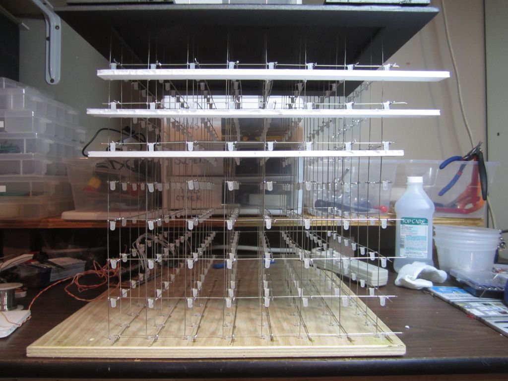
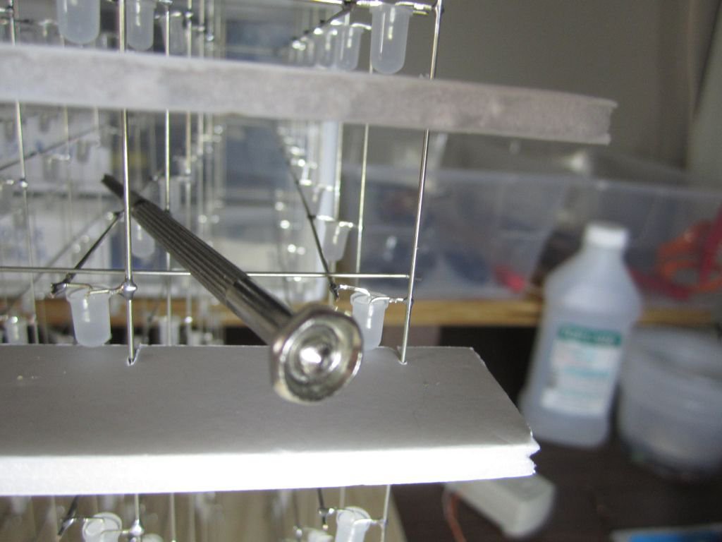
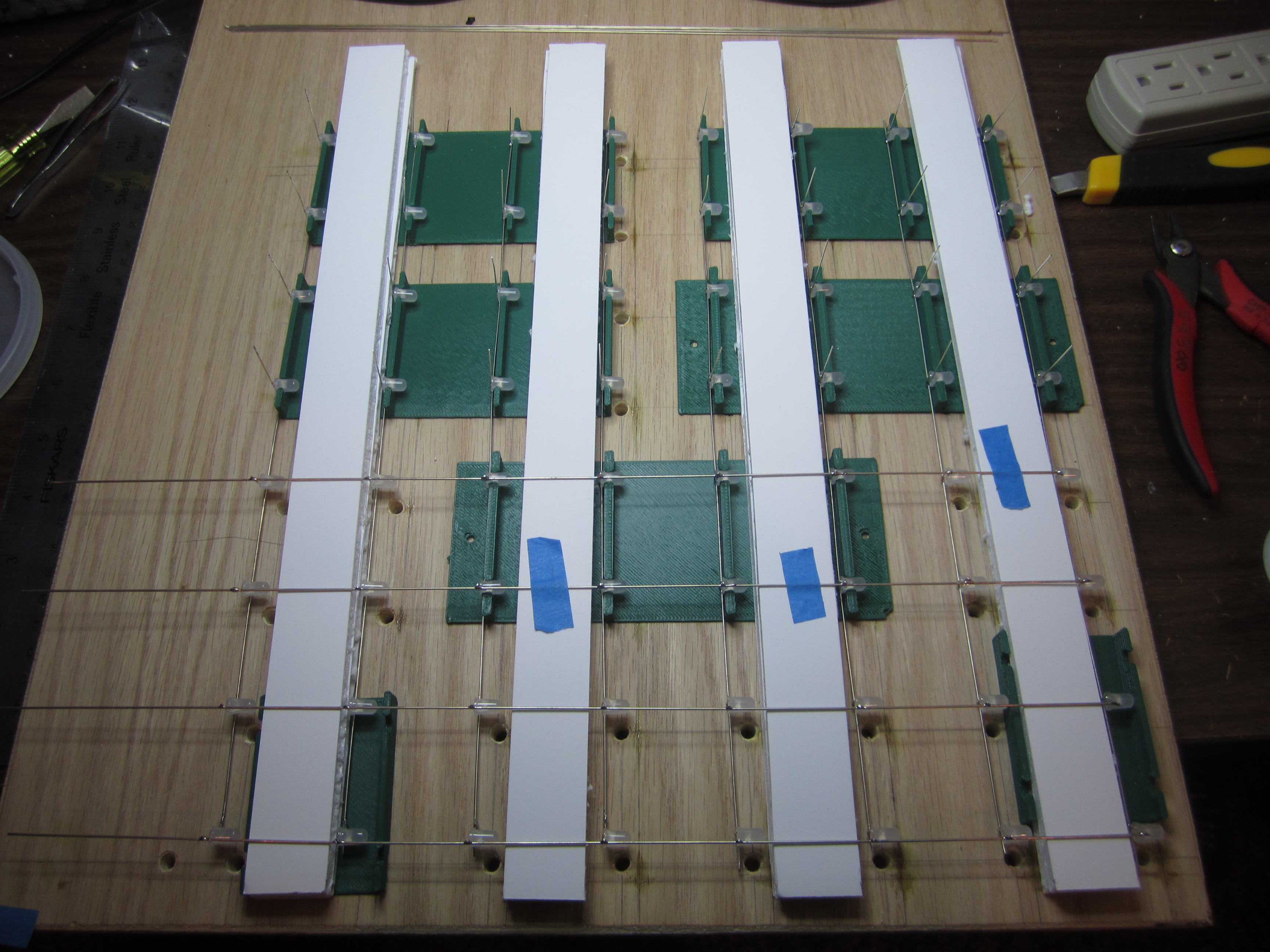
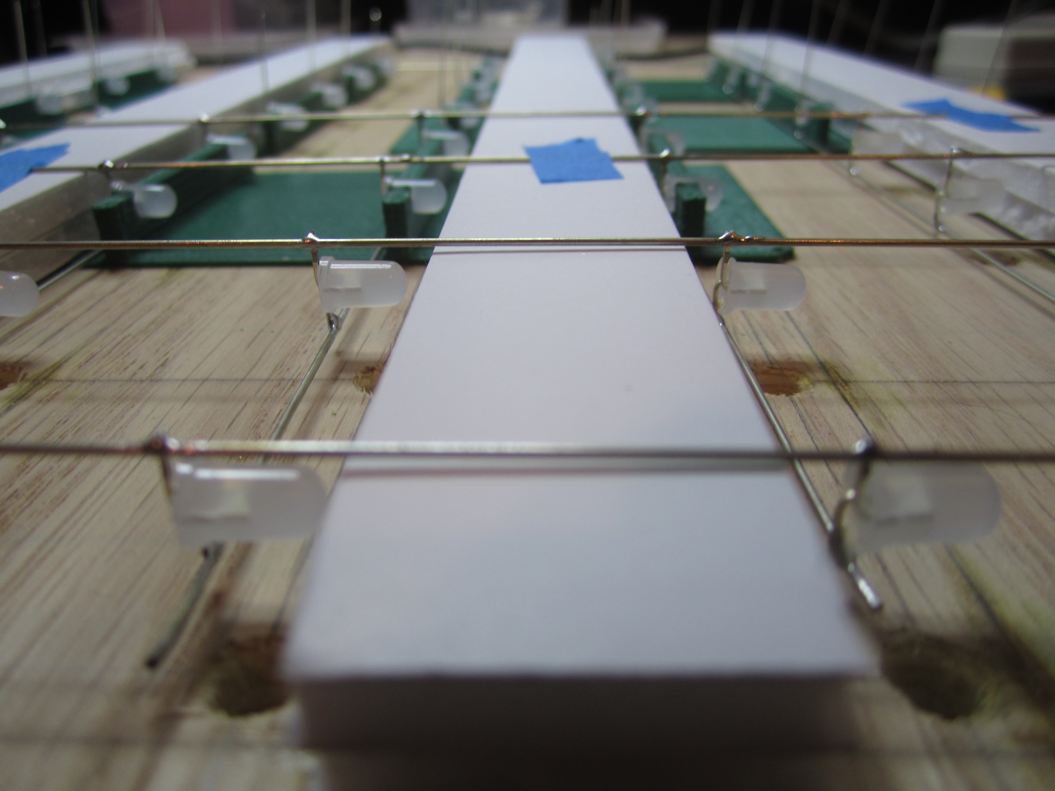
    Foam core board is my friend.  A very simple jig made of foam core with slits cut using a razor blade. Holds the wires at perfect 4cm spacing.

    This small screwdriver was just the right weight to lightly hold down on the wire that I'm soldering.

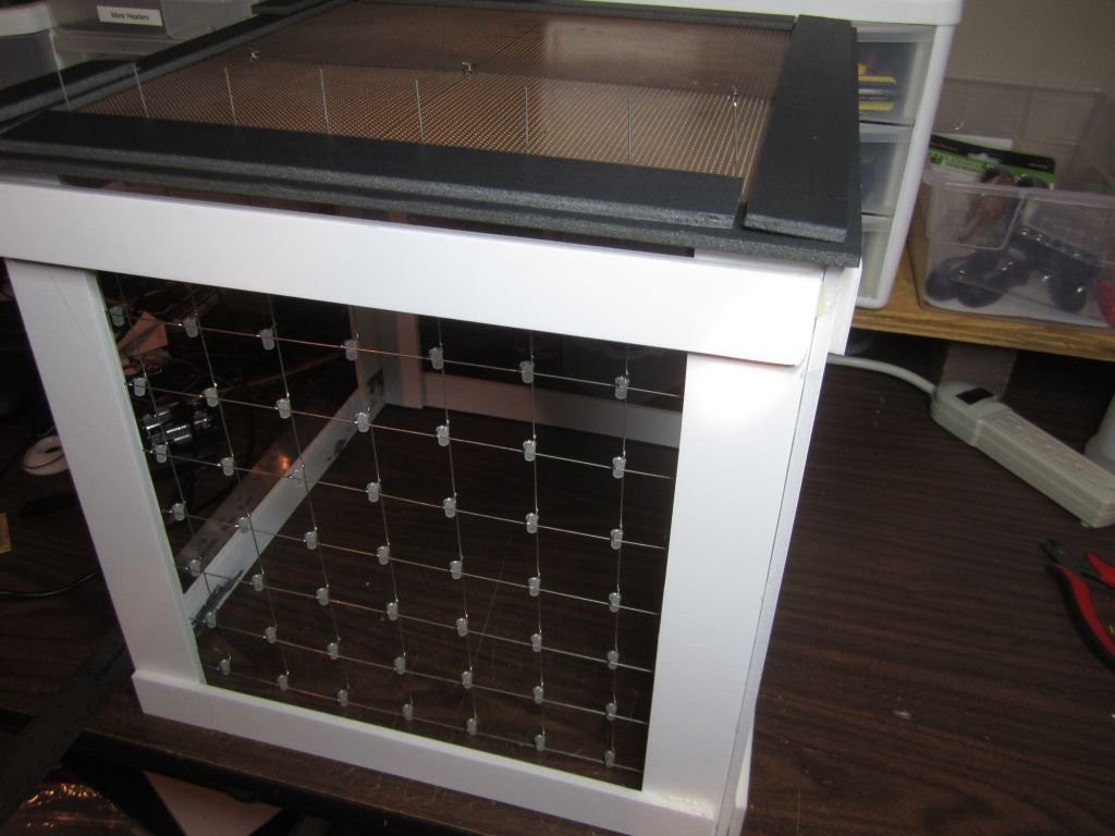
    I like how the cube looks when you're looking down the "aisles" rather than straight on the walls.  So I decided to make this the front of the cube.

  • The Base

    Hari Wiguna07/21/2014 at 00:57 1 comment

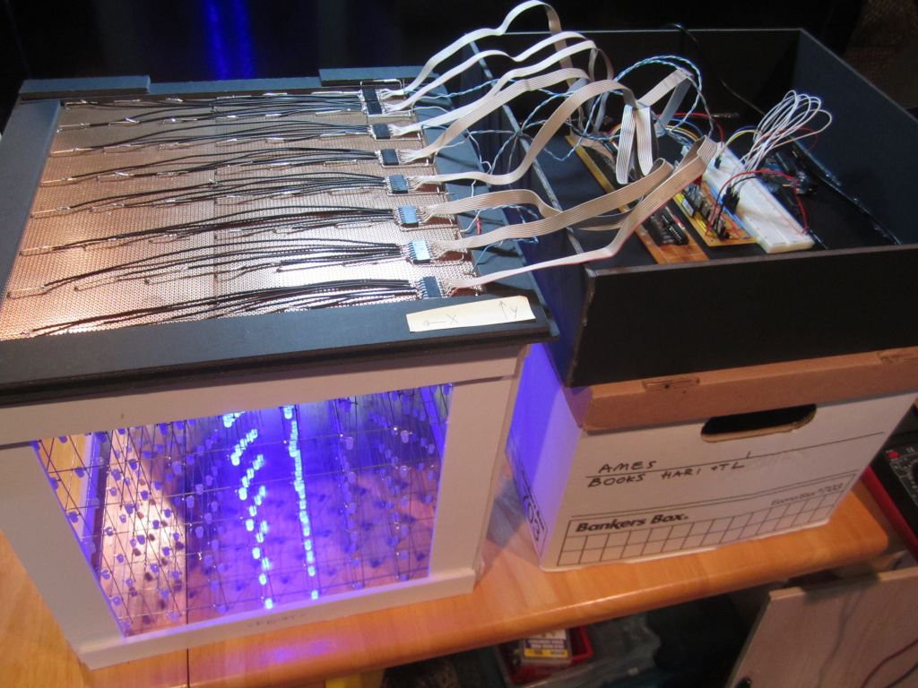
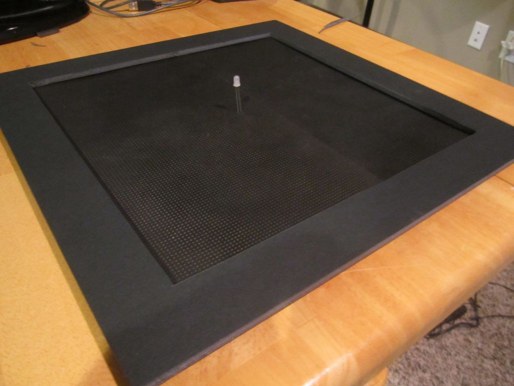
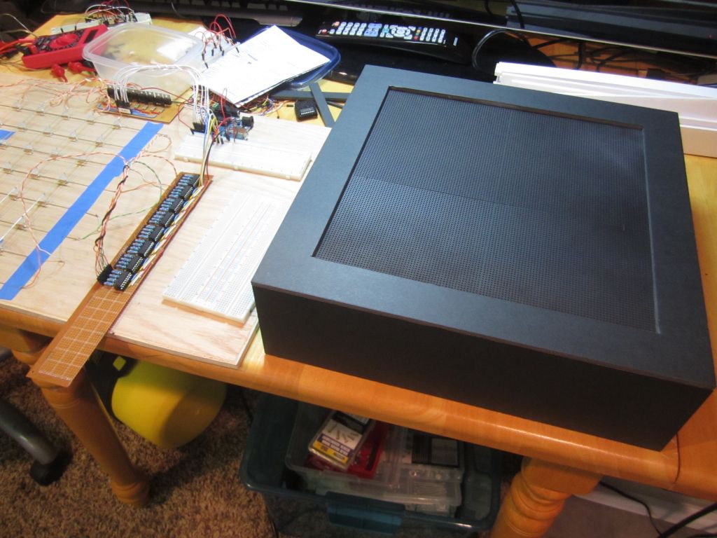
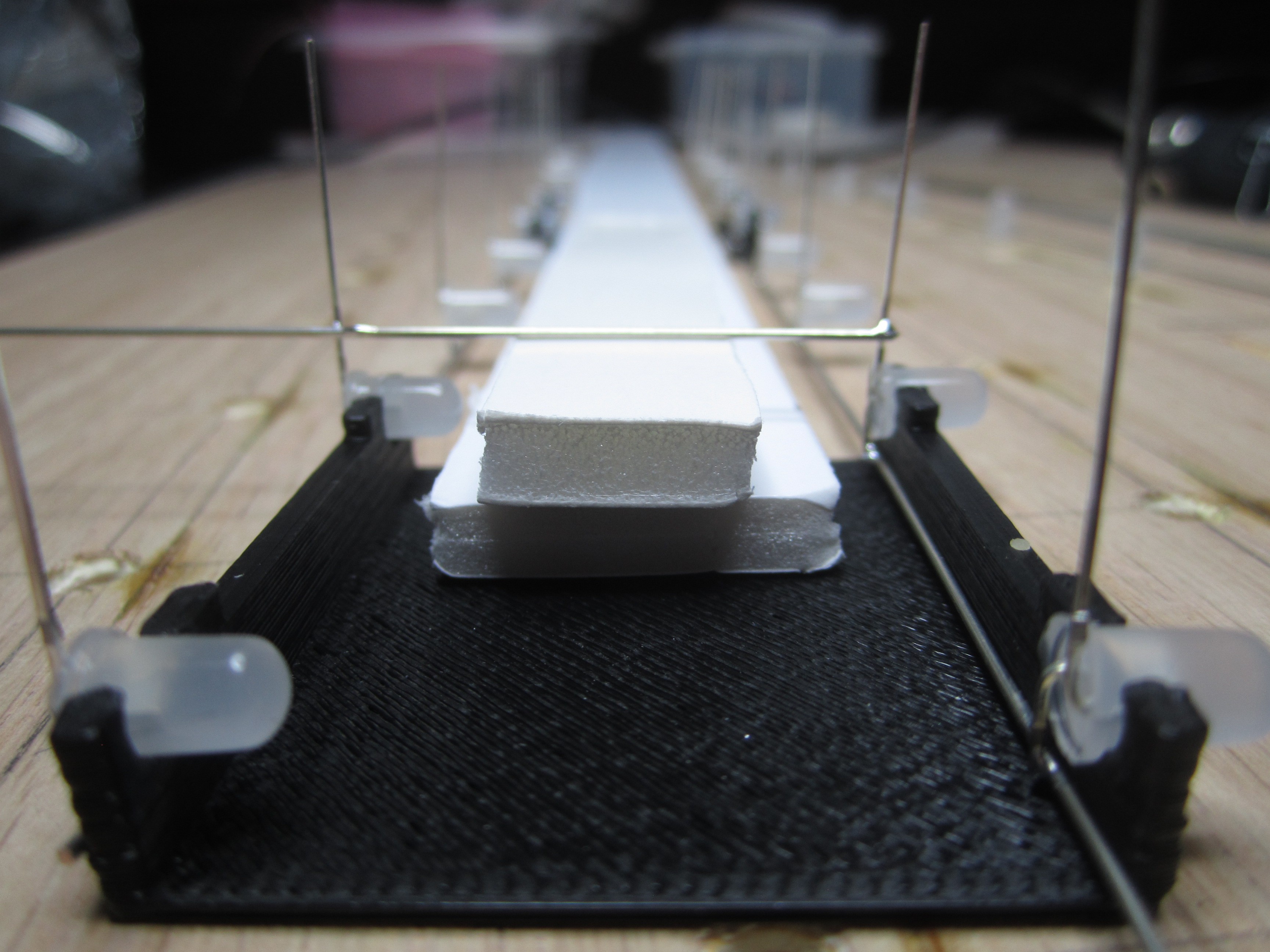
    The cube will be mounted on a PCB instead of a piece of wood.  Originally, I planned on putting all the components on this one board. That has the advantage of a very clean construction avoiding the ribbon cable mess between the LEDs and the shift register outpus.  However, I've since then decided to keep things modular so if I build another cube or came up with better circuit to drive the cube, I would have options.

    The frame you see below is black foam core board.  Inexpensive and very easy to work with.

    The cube is so large, the base had to be made of two PCBs.  

  • Shift Register board completed

    Hari Wiguna07/17/2014 at 00:38 0 comments

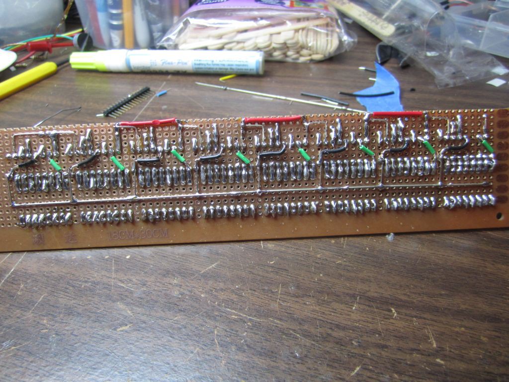
    Everything took longer than expected, but I am pleased with the result. 

    I did a continuity test after soldering each group of wiring.  That paid off!  The circuit worked the first time I plugged it in!

  • Layer MOSFET board completed

    Hari Wiguna07/14/2014 at 18:08 0 comments

    I decided to keep things modular, so the LEDs would be on one board, the column shift registers will be on another, and the layer MOSFETs on yet another PCB.

  • Amazing milestone

    Hari Wiguna06/29/2014 at 02:24 0 comments

    If you love LEDs, you got to see this. 

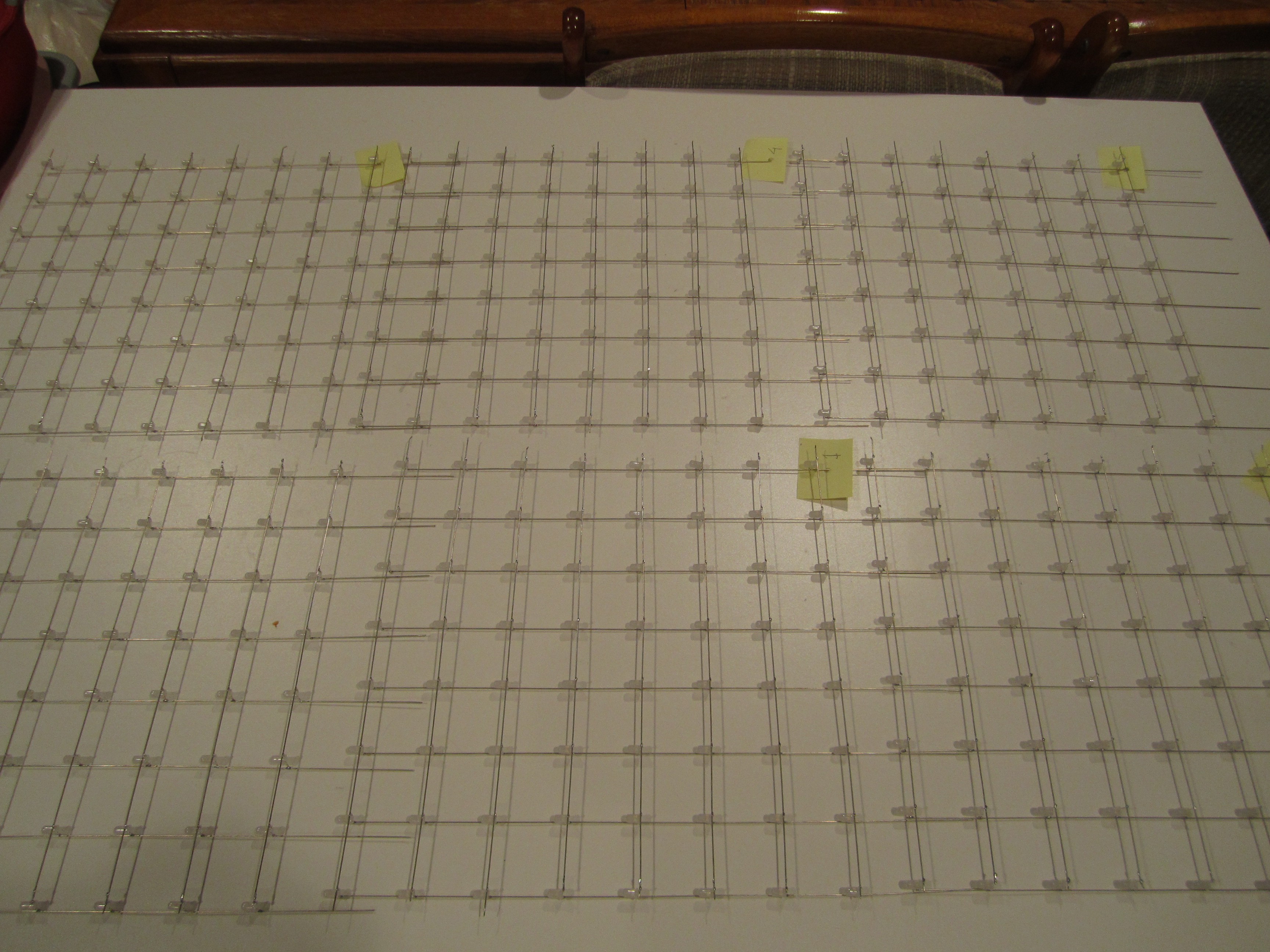
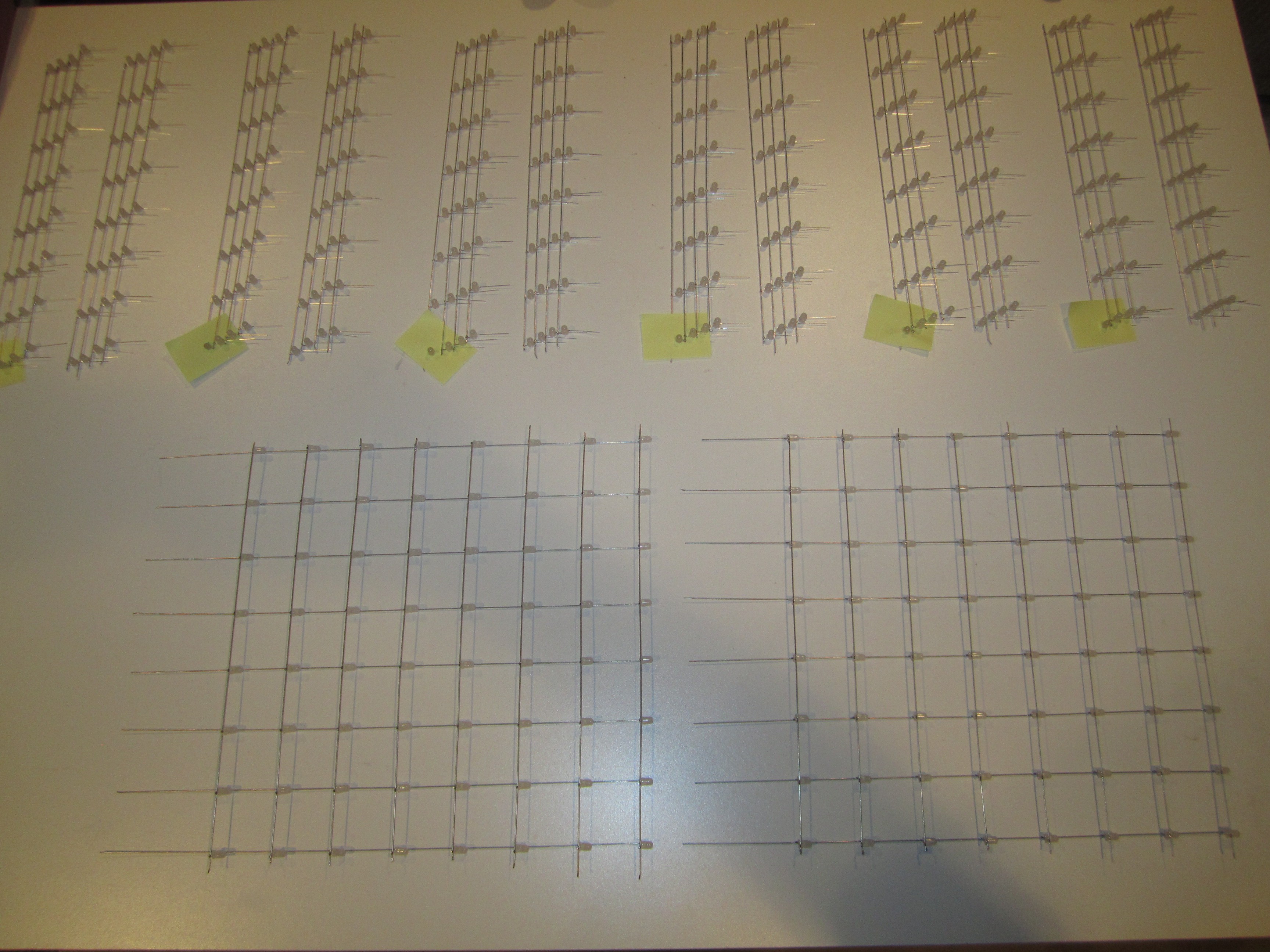
    LEDs taking over every open table surface :-) These are six of the eight walls.  There are two more 8x8 walls on another table.

  • Halfway there?

    Hari Wiguna06/24/2014 at 04:40 0 comments

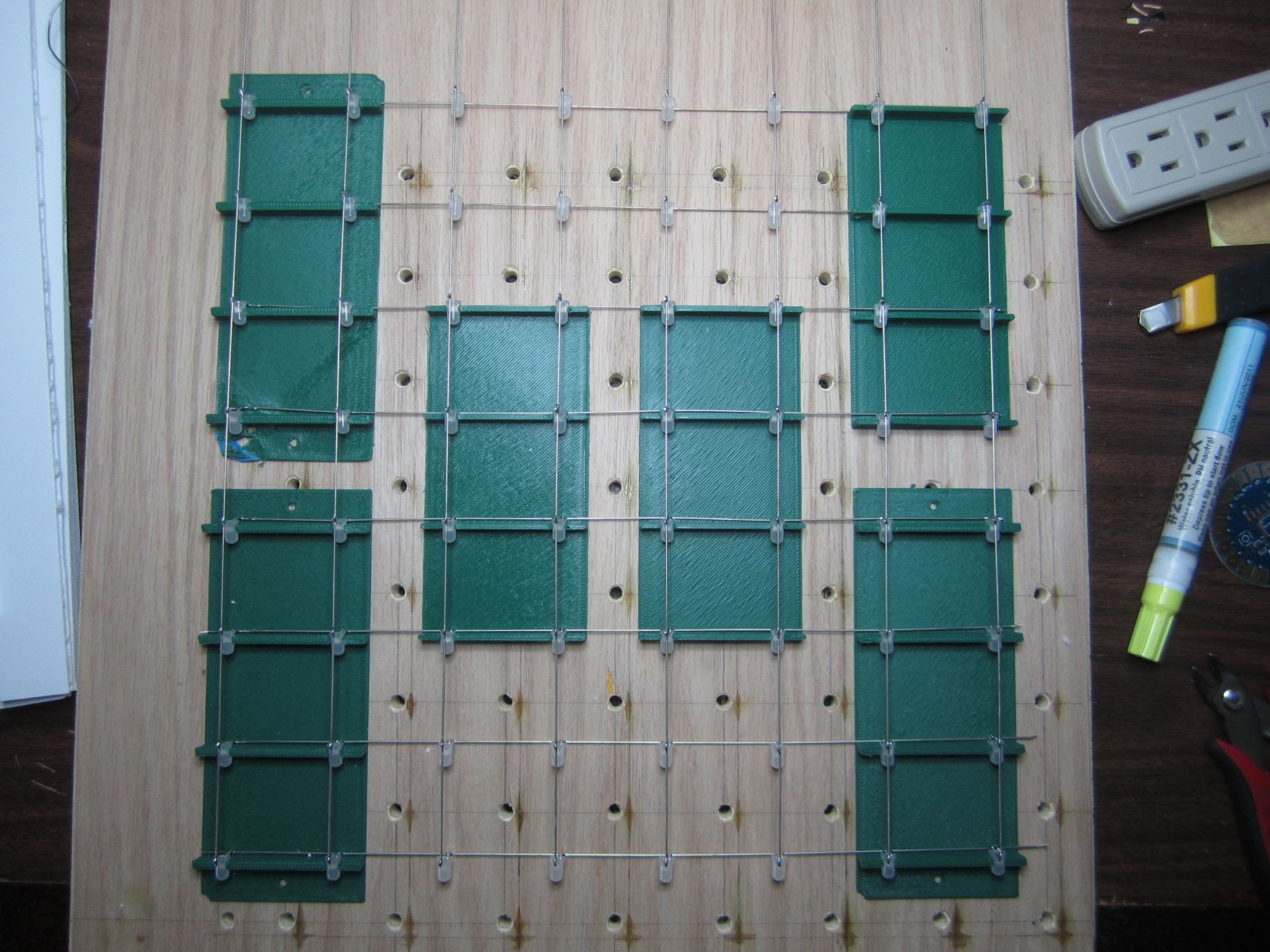
    These are all 512 LEDs that will make up the cube. There will be eight vertical walls of 64 LEDs each.  Two such walls have been completed. The other six walls still need to be soldered together (eight strands of eight LEDs each).  Should go pretty quick now that I have the 3D printed jig.

  • More jigs

    Hari Wiguna06/22/2014 at 17:36 0 comments

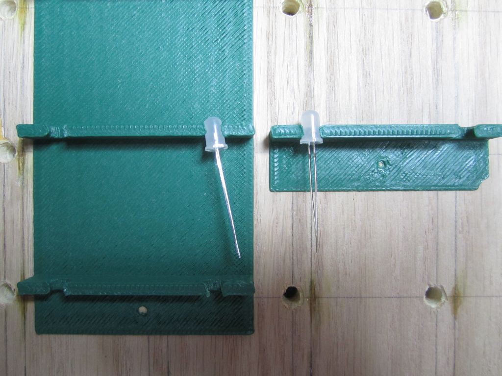
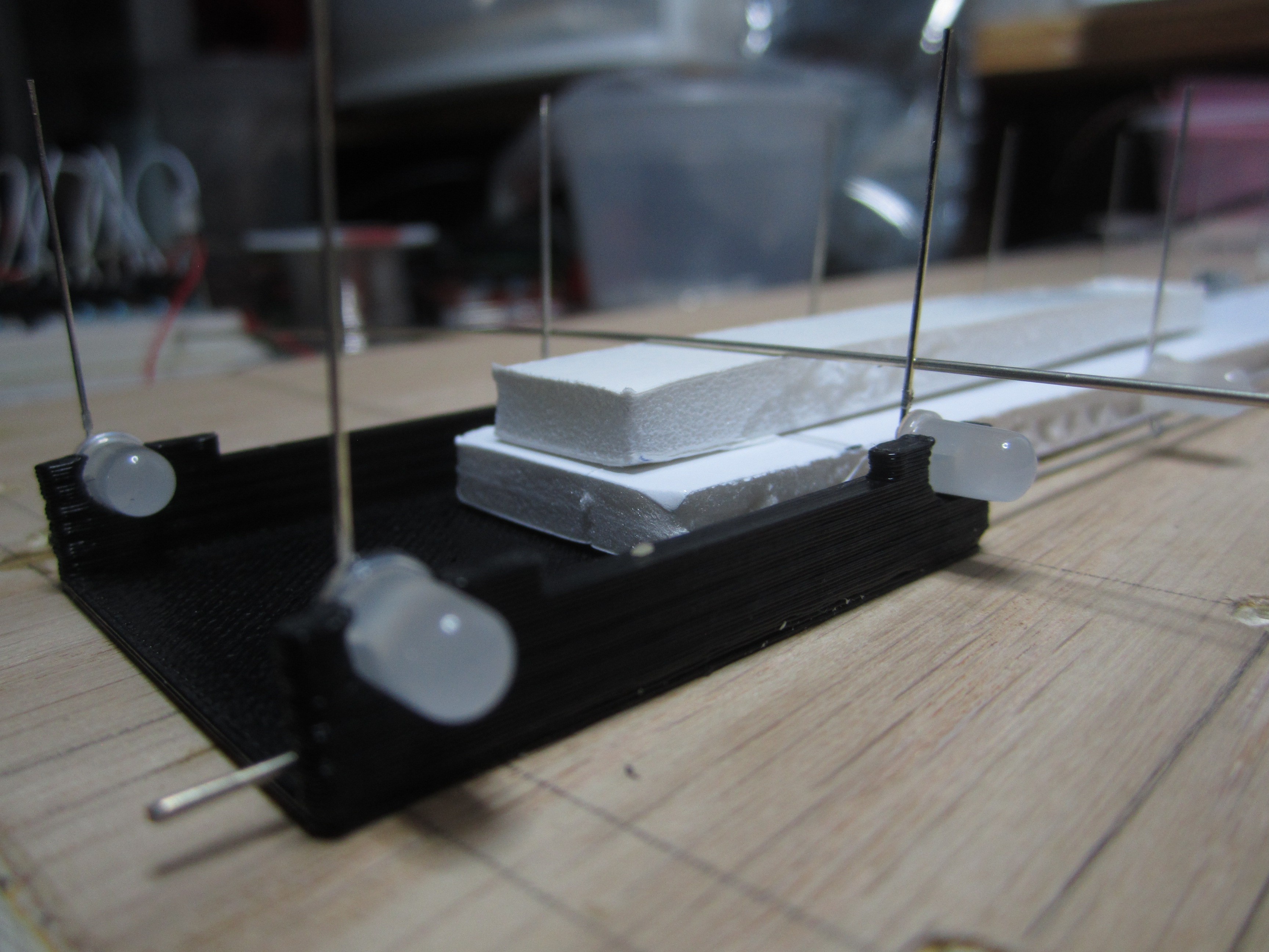
    I'm sure I'm making this harder than it needs to be, but it took several iterations to make the "vertical" jig.
    I probably should make even more so I don't have to keep moving them as I solder.

    I got impatient and increased the print speed on my printer and that lowered the print quality.  Note how the LED is held crooked.  Thankfully, I was able to straighten it out by holding soldering iron near the trouble spot and correct the hole by inserting an LED to reform the hole.

    With six jigs, the structure is finally rigid enough for soldering.  Here's one finished wall.  Horizontal wires are anodes that will be common per layer.  Vertical wires are cathodes (eight per wall, 64 total).  You can see the excess vertical wires at the top of this photo.  These will elevate the lowest layer 4cm above the base, so the cube would appear to be floating rather than resting on the base.

  • It's easier to do it when you're laying down

    Hari Wiguna06/17/2014 at 05:32 0 comments

    Thanks to my fellow makers BrianM and TonyF for helping me solve the forest of 64 vertical wires!  As you've seen from my previous updates, I've been soldering 64 LEDs as horizontal layers.  This is a mistake!!  Once I have all all eight layers, soldering in a forest of 64 vertical cathode wires would be very difficult if not impossible.  I've seen others solve this by creating pillars or vertical walls of LEDs instead of horizontal layers of LEDs.  The next problem is how to keep the vertical wires straight up while also keeping the LED rows lined up.  BrianM came up with a brilliant solution! Lay them flat on the table!  Although we're making a wall of LEDs, there is no reason why we can't lay them flat while we solder them.  I made a jig using my 3D printer and as you can see, it works very well.  I just need to print a few more so I can solder the whole wall at once without moving the jig.

View all 21 project logs

Enjoy this project?

Share

Discussions

Louis-Félix Germain wrote 09/21/2020 at 18:42 point

Is it possible to have more detailed schematics? The one already provided is incomplete

  Are you sure? yes | no

Phoenix wrote 12/04/2018 at 17:13 point

Nice Job! It really reminds me of the "blue-dot" section inside of Space Ship Earth at EPCOT.

  Are you sure? yes | no

mmaxlives wrote 12/11/2017 at 06:29 point

sir why Error compiling for board Arduino/Genuino Uno.

  Are you sure? yes | no

ActualDragon wrote 12/11/2017 at 11:36 point

you gotta be a bit more specific than that. It could be literally anything

  Are you sure? yes | no

Denis Revell wrote 11/04/2017 at 19:09 point

Hi, I have just built this project I used 330 ohm resistors, when the cube is all on I measured the current being drawn it was around 300ma and it's very bright in a darkened room I assume this is because its switching eight layers. I'm looking to find a way to make the display return to run continuously, every time I add a loop it comes with an error I am not very conversant with programming  I wondered if you could add this to your program, I managed to disable the touch sensors and the variable resistors in the program and just run the different displays as i haven't  put these on my cube  it works great, Thank you for spending your time on this project I'm sure everyone feels the same again many thanks.

  Are you sure? yes | no

Richard Winkelman wrote 09/02/2017 at 22:42 point

Sorry for this question. I am new to arduino and coding. I am putting together a small test bed so I can understand the total function of this cube. On your wiring diagram the input from the arduino to the power side, you have it labeled net label. And it says To Arduino pin to control the layers.  I look in the code you've written  and I do not see a call out for these other than for the shift registers . It maybe because I do not completely understand what I am looking at. But I have built this test board a couple of times and it fails every time and I think I am doing something wrong. 

  Are you sure? yes | no

Hari Wiguna wrote 09/03/2017 at 07:13 point
It's not you. That is unclear and I actually had to relearned it to figure it out! :-)
If you look at this version:
https://github.com/hwiguna/g33k/tree/master/ArduinoProjects/8x8x8LEDCube/_8x8x8_lue_LED_cube16

in setup.ino you will see that we setup three output pins for the shift register's latch, clock, and data.

Then we setup eight more pins for output starting with pin 2 to pin 9.  Those are the Arduino pins that controls which layer/level of the cube should be on.  So first "net label" should go to Arduino D2, second "net label" goes to D3, etc.

Let me know if that's still unclear.  As I said, it's not you. I should have documented it better. Sorry...

  Are you sure? yes | no

Richard Winkelman wrote 09/03/2017 at 17:04 point

Thank you very much for clarifying . I am going to atempt to make a new diagram and I will post it here., Thanks for the quick reply. 

  Are you sure? yes | no

Hari Wiguna wrote 08/13/2017 at 14:43 point
Sorry I missed all the code requests.  It's been on github all along, but here is the link:
https://github.com/hwiguna/g33k/tree/master/ArduinoProjects/8x8x8LEDCube

  Are you sure? yes | no

Richard Winkelman wrote 08/14/2017 at 22:20 point

Thank you for the update . Greatly appreciated! 

  Are you sure? yes | no

Richard Winkelman wrote 08/13/2017 at 13:54 point

I got all the stuff to start this project.  I am starting it today.  Thanks for this awesome project. I also would like to get my hands on the project code if you could. Thanks. 

  Are you sure? yes | no

009palash wrote 08/09/2017 at 21:33 point

Request to send arduino code

  Are you sure? yes | no

Wasyx wrote 01/20/2017 at 14:16 point

What an amazing build! I already created the cube itself. Tested the layers and collums with some breadboard electronics. Seems that I am better in soldering than coding...... Can you (or anyone) direct me to some code for this project? Preferably for arduino mega/uno?

  Are you sure? yes | no

Alkesh.eng wrote 01/12/2017 at 10:03 point

Request to send arduino code  at Alkesh.eng@gmail.com

  Are you sure? yes | no

Alkesh.eng wrote 01/12/2017 at 10:03 point

Request to send arduino code  at Alkesh.eng@gmail.com

  Are you sure? yes | no

Joshuadukate wrote 10/05/2016 at 15:26 point

I didnt have a big enough perfboard for the mosfet board so I halfway designed a board in pcb express.

  Are you sure? yes | no

Joshuadukate wrote 10/05/2016 at 06:04 point

I have built the cube, shift register board, and the mosfet board I will post pictures up soon. This is an amazing project.

  Are you sure? yes | no

Hari Wiguna wrote 10/05/2016 at 12:36 point

No, YOU're amazing! I know how much work it was to build. Yes, I'd love to see your cube.

  Are you sure? yes | no

smunroe7 wrote 05/08/2016 at 16:35 point

I see that you used 220ohm resisters for your cube. I'm building a 6x6 cube and calculated that I would need only 60ohm resisters so I went with 100ohm. I'm hoping that will be suffice. I had a question regarding grounding. Can I use the general 2N222A transisters to ground my layers? 

  Are you sure? yes | no

smunroe7 wrote 05/08/2016 at 16:39 point

I just saw the comment below about having to ground 15ma * 64. I have these LEDs so would I have to do 30ma * 32 to get my max amperage? http://www.ebay.com/itm/100-pcs-5mm-round-Blue-LED-superbright-bulb-lamp-light-/181138821071?hash=item2a2cb70fcf:g:Q1sAAOxyOa9Rz-Oq

  Are you sure? yes | no

Hari Wiguna wrote 05/08/2016 at 17:54 point
If I recall correctly, I experimented on the resistor value based on bright I wanted the LEDs to light up.  I discovered that I did not need 30mA to make the leds bright enough.  However, even with less than 30mA per led, I think you woud still need more than a 2N222 to power 36 leds.  One way to find out... wire up 36 leds on breadboard. :-) Good luck!  Would love to see the finished cube when you get it done!

  Are you sure? yes | no

Hari Wiguna wrote 05/08/2016 at 17:54 point

If I recall correctly, I experimented on the resistor value based on bright I wanted the LEDs to light up.  I discovered that I did not need 30mA to make the leds bright enough.  However, even with less than 30mA per led, I think you woud still need more than a 2N222 to power 36 leds.  One way to find out... wire up 36 leds on breadboard. :-) Good luck!  Would love to see the finished cube when you get it done!

  Are you sure? yes | no

DottiL wrote 04/04/2016 at 20:10 point

Hello Hari, I'm trying to build an 8x8x8 led cube and I found this very nice tutorial. I have some doubts which I wish you cold clarify. Every led take up to 20 mA and every shift register take care of 8 columns. Since only one layer is light up at time, we can have at most 8 led light up for each shift register for a total of 160 mA. How can you handle that current with the 74hc595? Are you multiplexing also on the shift register themselves? Meaning that you light up only one column at time?

Thank you

  Are you sure? yes | no

Hari Wiguna wrote 04/05/2016 at 01:26 point

I'm setting up the pattern for the whole row on the shift registers and then turn on the MOSFET.  Maybe since EACH I/O pin only drives one LED at a time, it's ok for all 8 I/O pins of each shift register to be on at once -- each only grounding 20mA.  Also, each level is only on for a very short time, so that also decreases the average current.
Please share a link if/when you build yours.  Love to see it.

  Are you sure? yes | no

DottiL wrote 04/05/2016 at 21:33 point

Hello, thank for the reply.  But still can get how this could work. Is it true that each pin can handle 35 mA each, but the ground for the 74hc595 is only 70 mA. Sorry if Im so pedantic, but I have to order the components and I don't want to make a wrong order.  

  Are you sure? yes | no

Hari Wiguna wrote 04/06/2016 at 00:40 point

I can't explain it either, but I've just taken this photo.

https://goo.gl/photos/orn26Q83RMnNiqEX9

As you can see it really is a 74HC74595.  One last possible explanation might be that each pin passes less than 20mA due to the current limiting resistor.  All I know is that it works and nothing blew up.  If it makes you feel better you could put transistors on that side as well, but that's going to be 64 more transistors! yikes! :-o

  Are you sure? yes | no

DottiL wrote 04/06/2016 at 07:41 point

That's weird and probably yes you are passing less current than 20 mA. Btw I found that tpic6b595 IC can handle such current (500 mA) and I will use them as sink for the 64 cathode columns and a 74HC595 in combination with mosfets for the layers. Thanks anyway for the informations and stay tuned for my led cube :)

  Are you sure? yes | no

Roman M wrote 03/03/2016 at 21:52 point
See amazing LED project here: http://kck.st/1Oi2sHC
Simply and affordable...

  Are you sure? yes | no

fatsam00 wrote 04/08/2015 at 06:30 point

Nice and cool project to build. But what i dont understand is why do we need those mosfets. and also i was saerching for the 74H series shift registers but couldnt find one at my local market. What kind of shift register can i use as an alternative?

  Are you sure? yes | no

davedarko wrote 04/08/2015 at 07:48 point

There are 64 LEDs on a layer that all could be on at one time, so you would need something that can switch 64 * 15mA = 960mA at once - Layer for layer. Look for 8-Bit shift registers, but they may not be pin compatible.

  Are you sure? yes | no

Hari Wiguna wrote 04/08/2015 at 12:40 point

Thanks.  As Dave said, it is because for each layer, up to 64 LEDs could be on at the same time. 

  Are you sure? yes | no

dave wrote 01/29/2015 at 22:21 point

Looks great, very nice.

  Are you sure? yes | no

Hari Wiguna wrote 01/29/2015 at 22:26 point

Thank you for taking the time to leave positive feedback David!

  Are you sure? yes | no

davedarko wrote 01/07/2015 at 10:29 point

@Frankstripod and @Hari Wiguna - you guys may be interested in that? http://hackaday.io/project/181-mearm-pocket-sized-robot-arm/log/12633-hackaday-munich-mearm-giveaway - thought of you guys because of the good old days we enjoyed the updates of this project :)

  Are you sure? yes | no

frankstripod wrote 07/30/2014 at 06:26 point
Nice work! Looks like I am third to suggest different shapes. Maybe in the future you will develop an inconspicuous way to reinforce less stable shapes.

  Are you sure? yes | no

Similar Projects

Does this project spark your interest?

Become a member to follow this project and never miss any updates