Hari Wiguna
-
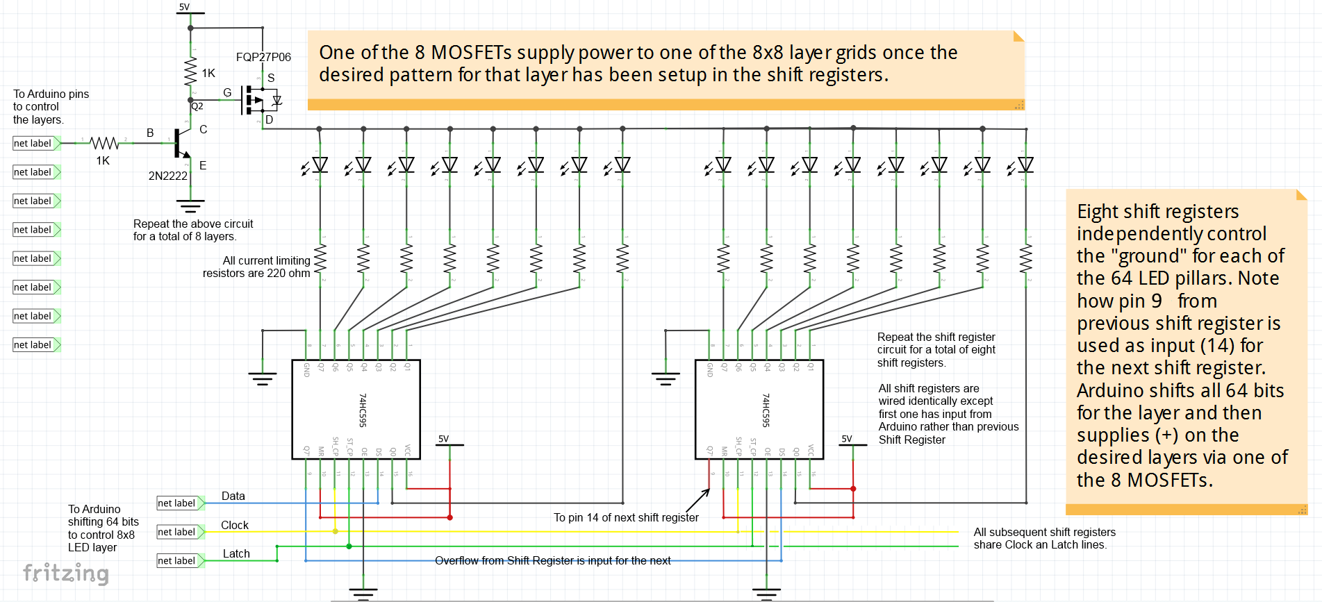
Circuit Diagram
12/05/2014 at 01:16 • 1 commentClick to see larger version.
-
Added Touch Sensors
07/26/2014 at 13:30 • 0 comments -
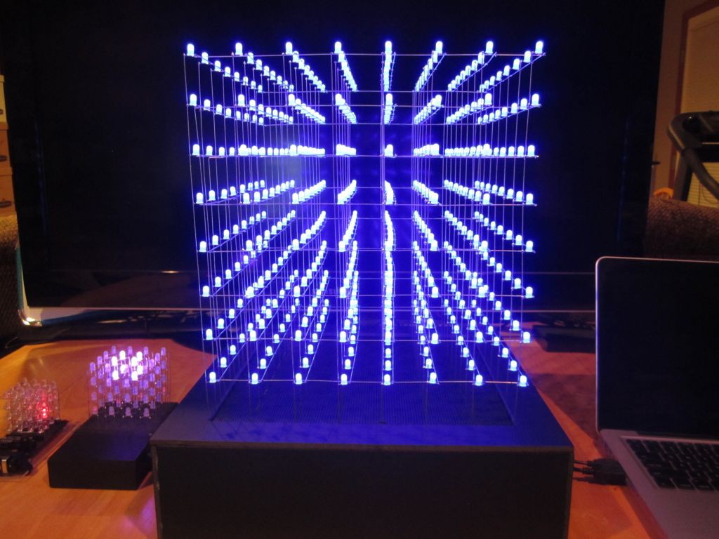
It's done!
07/24/2014 at 23:47 • 0 comments![]()
![]()
Instead of counting holes on the PCB, I used a piece of paper as a jig.
![]()
![]()
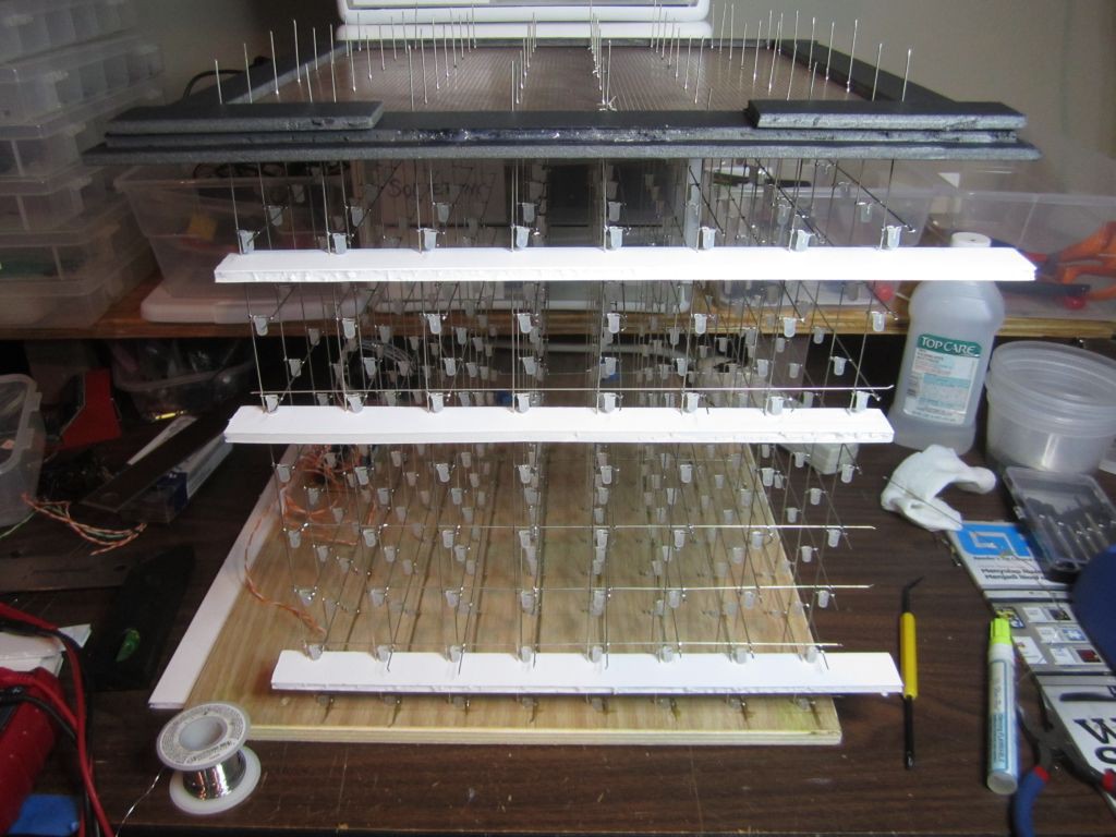
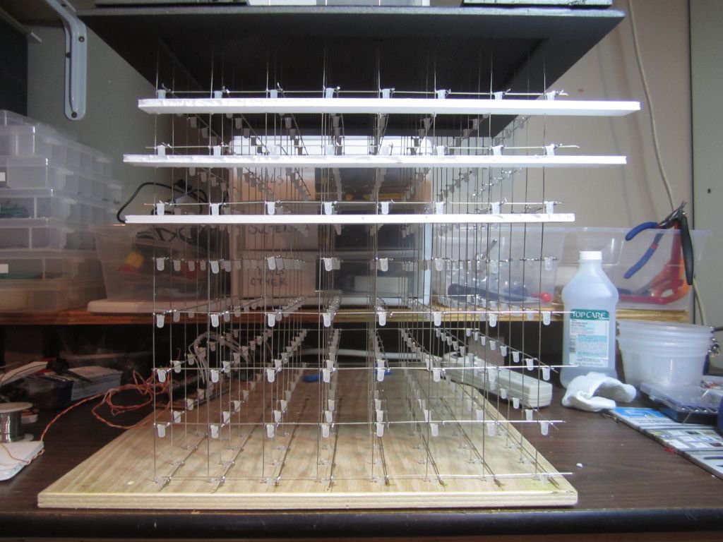
All the top LEDs are rested in the holes of the wooden jig. It was standing like this while I solder all the cross wires.
![]()
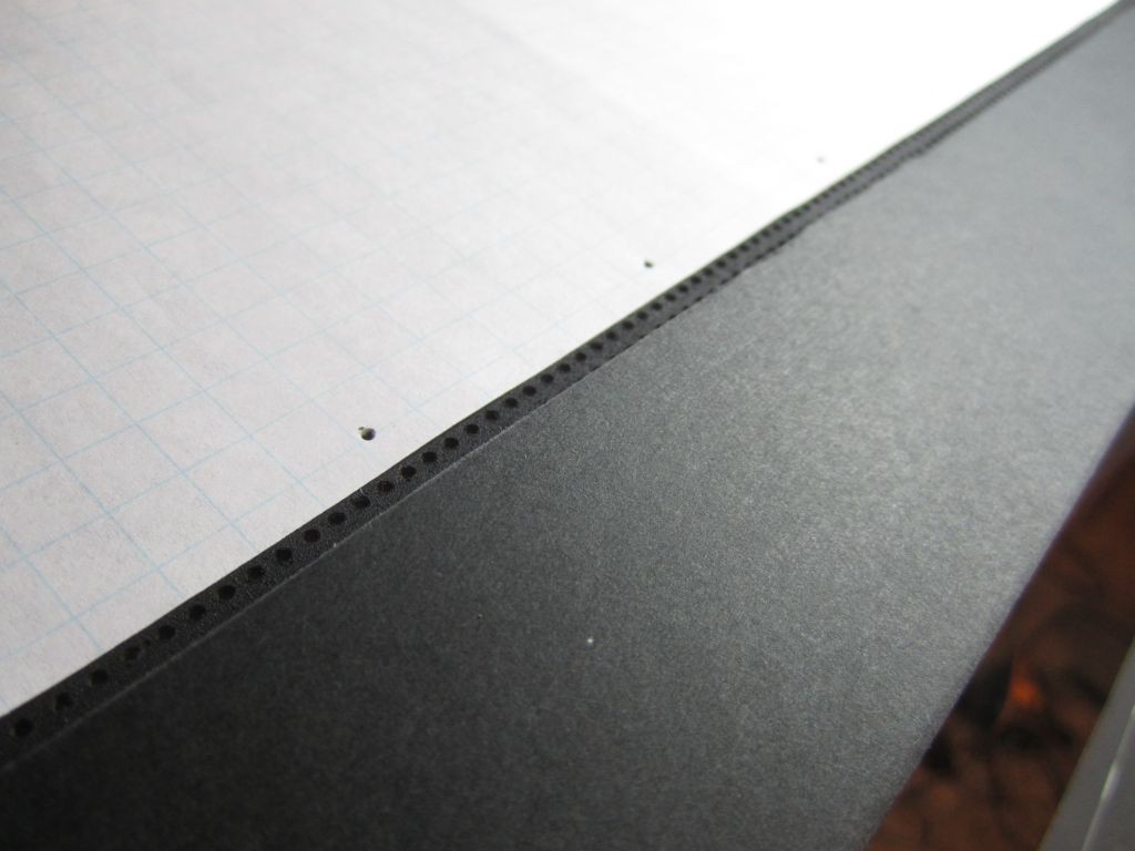
Foam core board is my friend. A very simple jig made of foam core with slits cut using a razor blade. Holds the wires at perfect 4cm spacing.
![]()
![]()
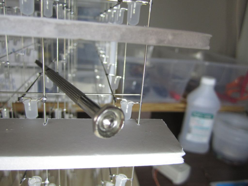
This small screwdriver was just the right weight to lightly hold down on the wire that I'm soldering.
![]()
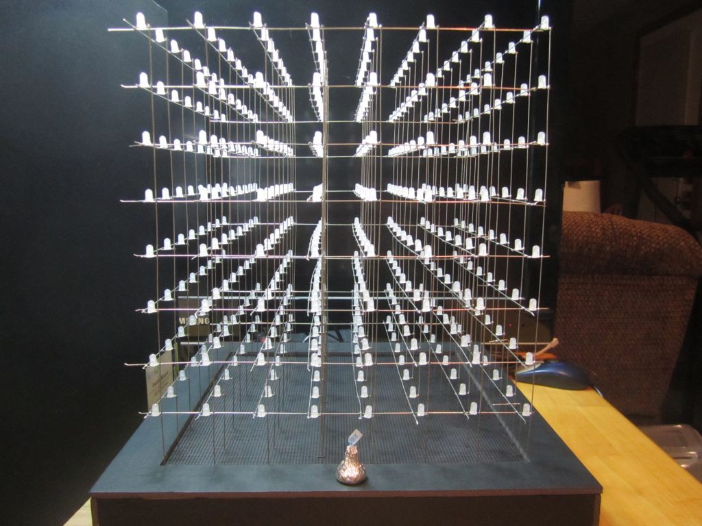
I like how the cube looks when you're looking down the "aisles" rather than straight on the walls. So I decided to make this the front of the cube.
![]()
![]()
![]()
![]()
![]()
![]()
-
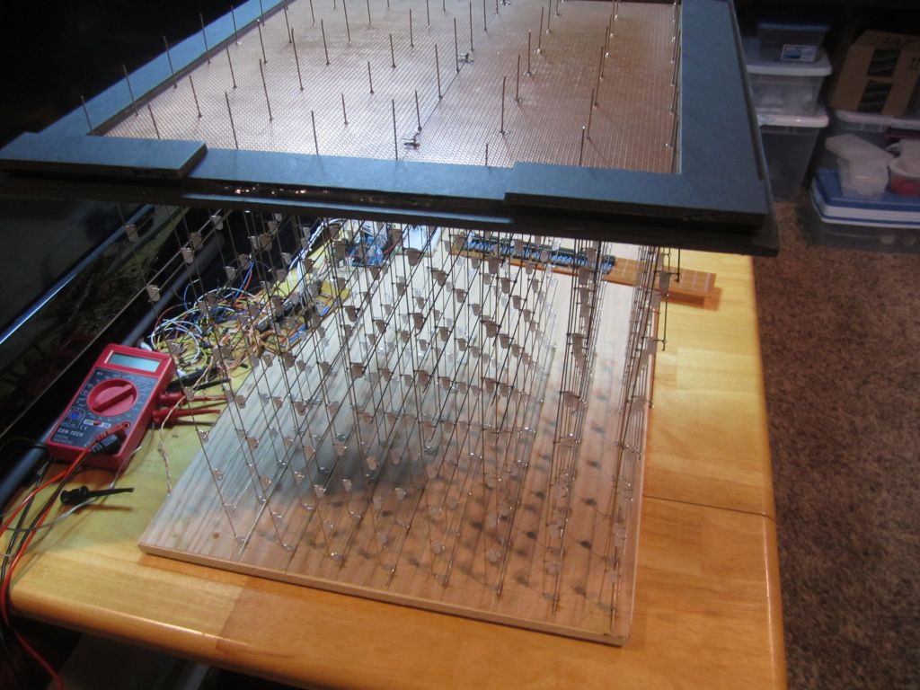
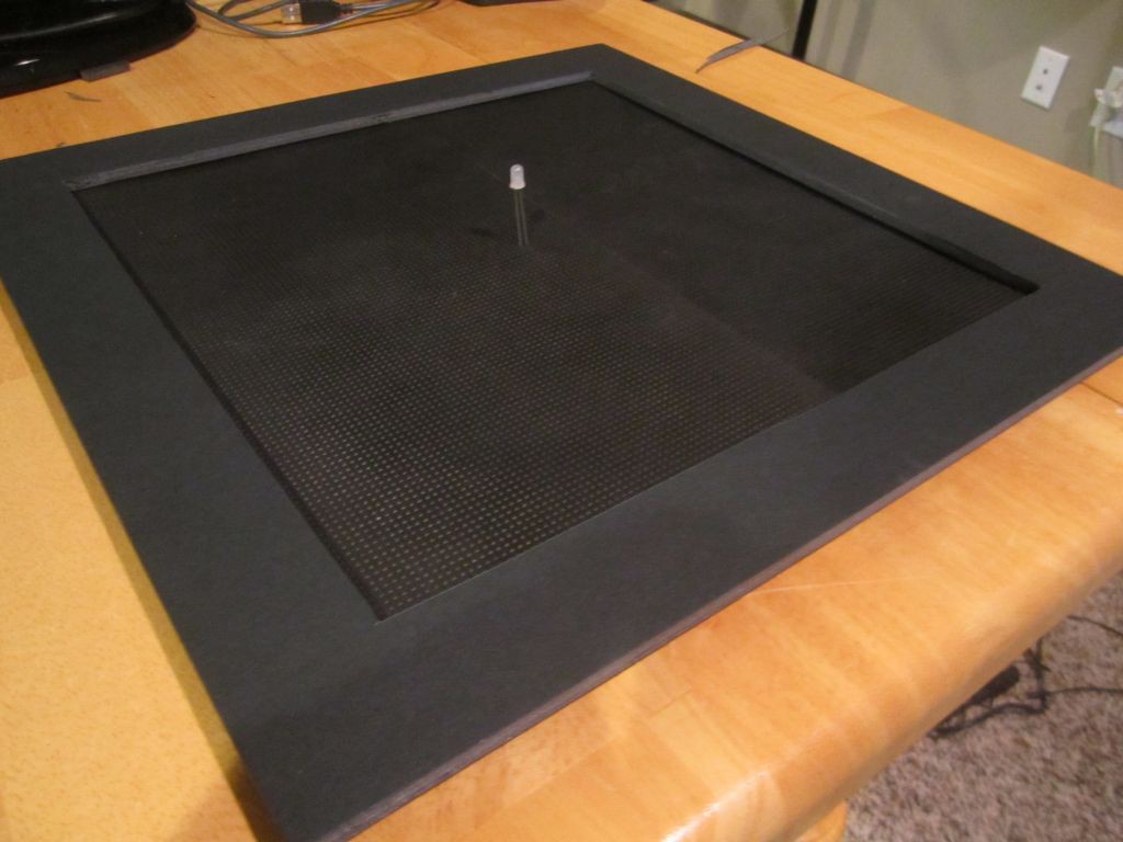
The Base
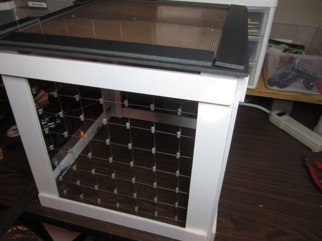
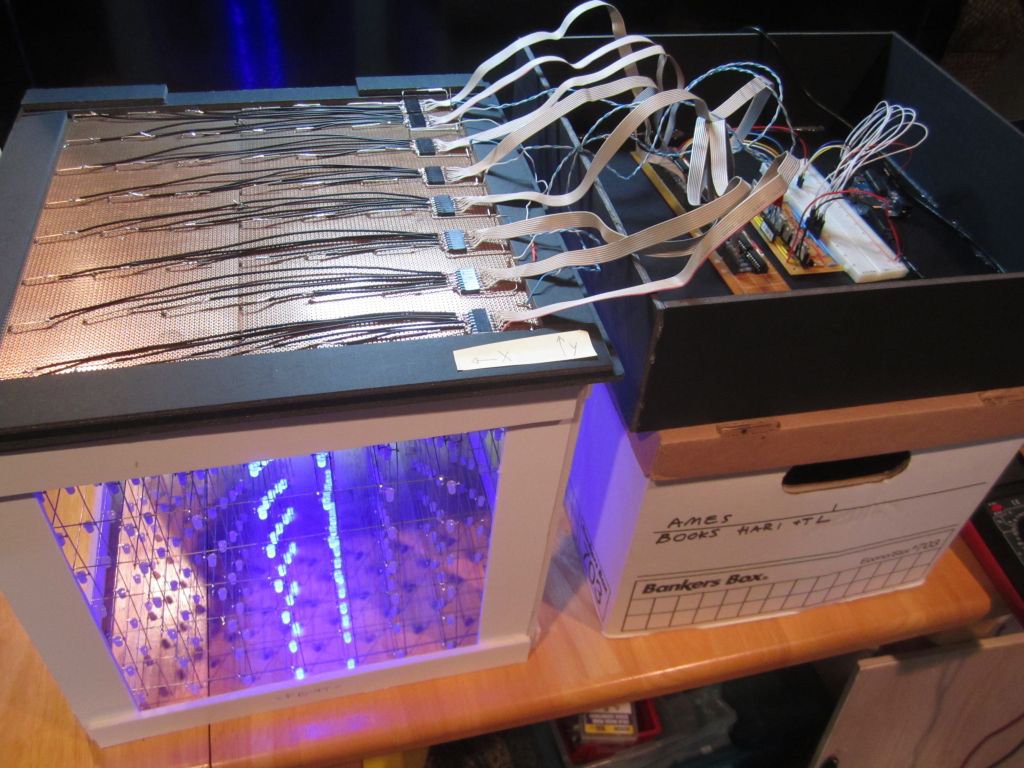
07/21/2014 at 00:57 • 1 commentThe cube will be mounted on a PCB instead of a piece of wood. Originally, I planned on putting all the components on this one board. That has the advantage of a very clean construction avoiding the ribbon cable mess between the LEDs and the shift register outpus. However, I've since then decided to keep things modular so if I build another cube or came up with better circuit to drive the cube, I would have options.
The frame you see below is black foam core board. Inexpensive and very easy to work with.
![]()
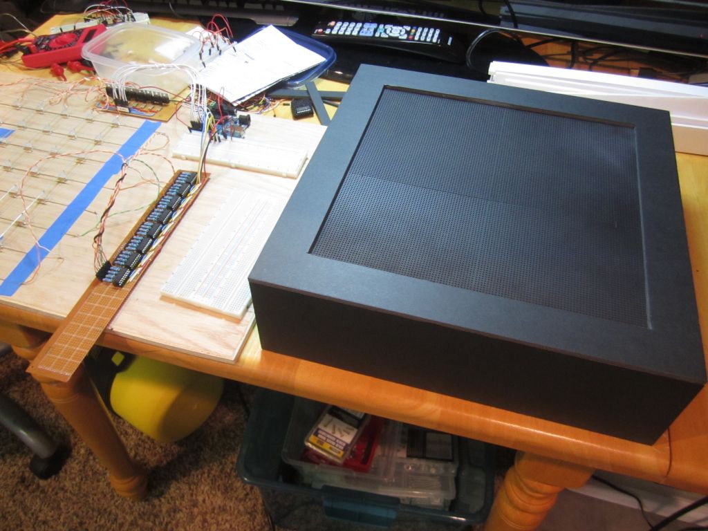
The cube is so large, the base had to be made of two PCBs.
![]()
-
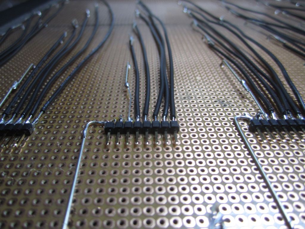
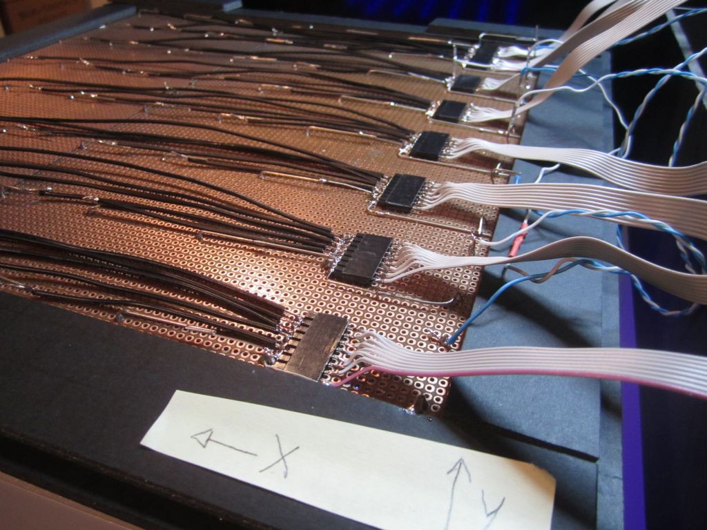
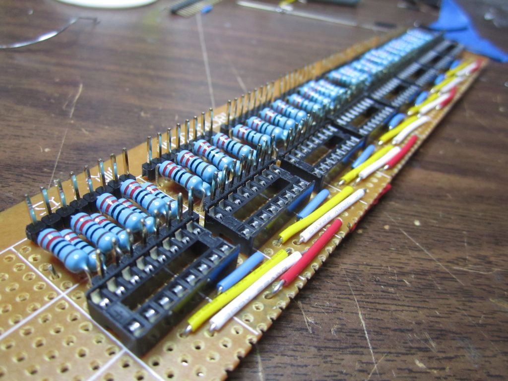
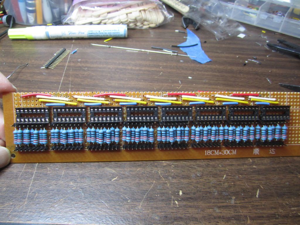
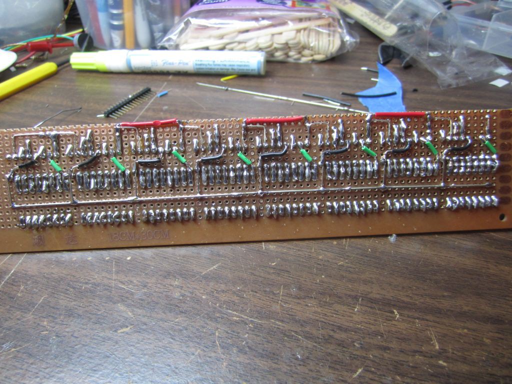
Shift Register board completed
07/17/2014 at 00:38 • 0 commentsEverything took longer than expected, but I am pleased with the result.
I did a continuity test after soldering each group of wiring. That paid off! The circuit worked the first time I plugged it in!
![]()
![]()
![]()
-
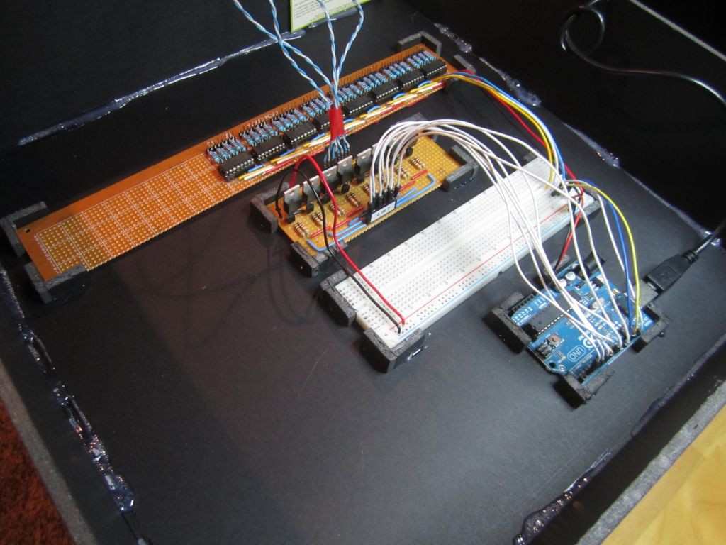
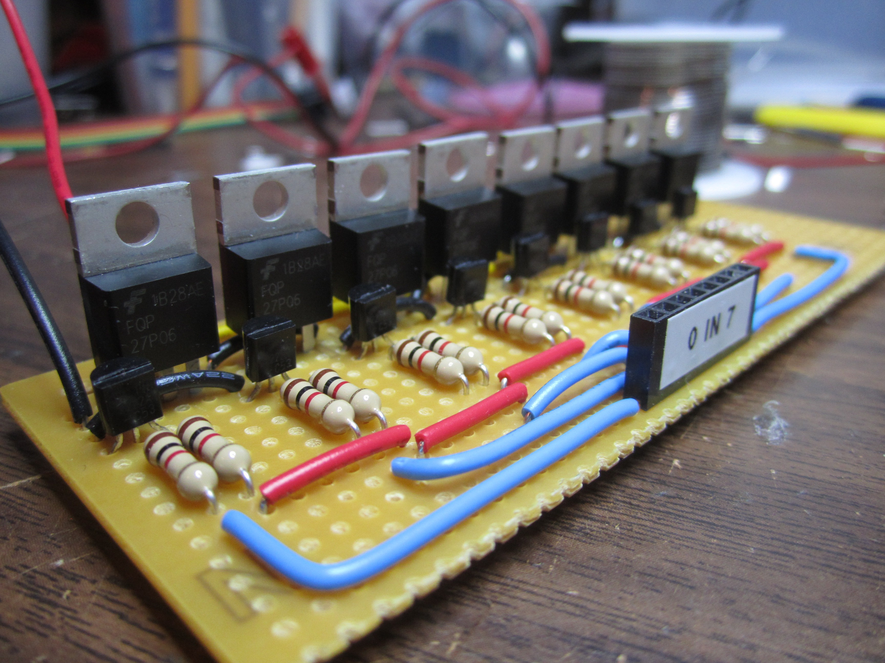
Layer MOSFET board completed
07/14/2014 at 18:08 • 0 commentsI decided to keep things modular, so the LEDs would be on one board, the column shift registers will be on another, and the layer MOSFETs on yet another PCB.
![]()
![]()
-
Amazing milestone
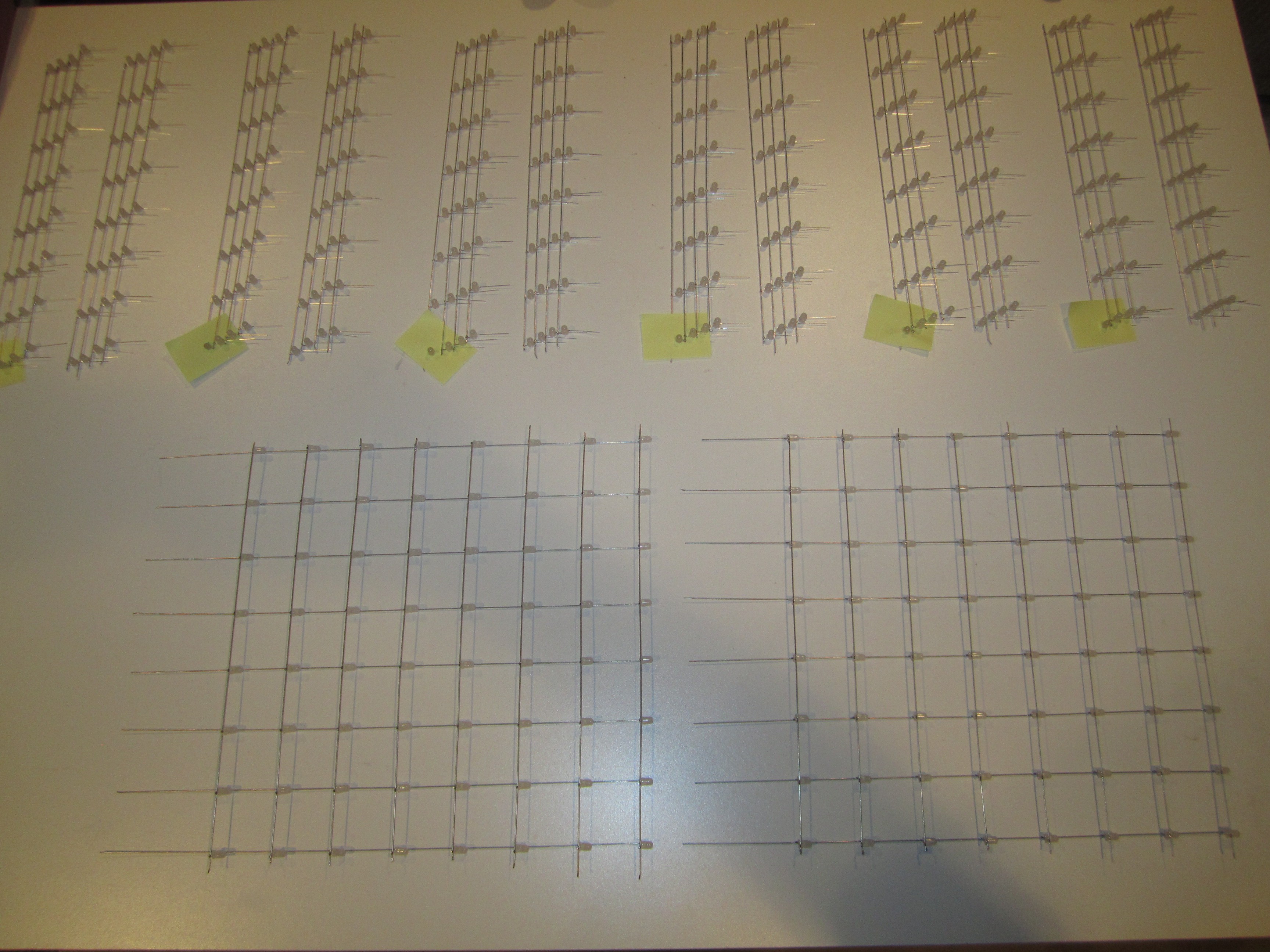
06/29/2014 at 02:24 • 0 commentsIf you love LEDs, you got to see this.
LEDs taking over every open table surface :-) These are six of the eight walls. There are two more 8x8 walls on another table.
![]()
-
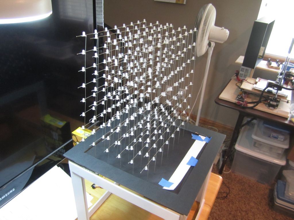
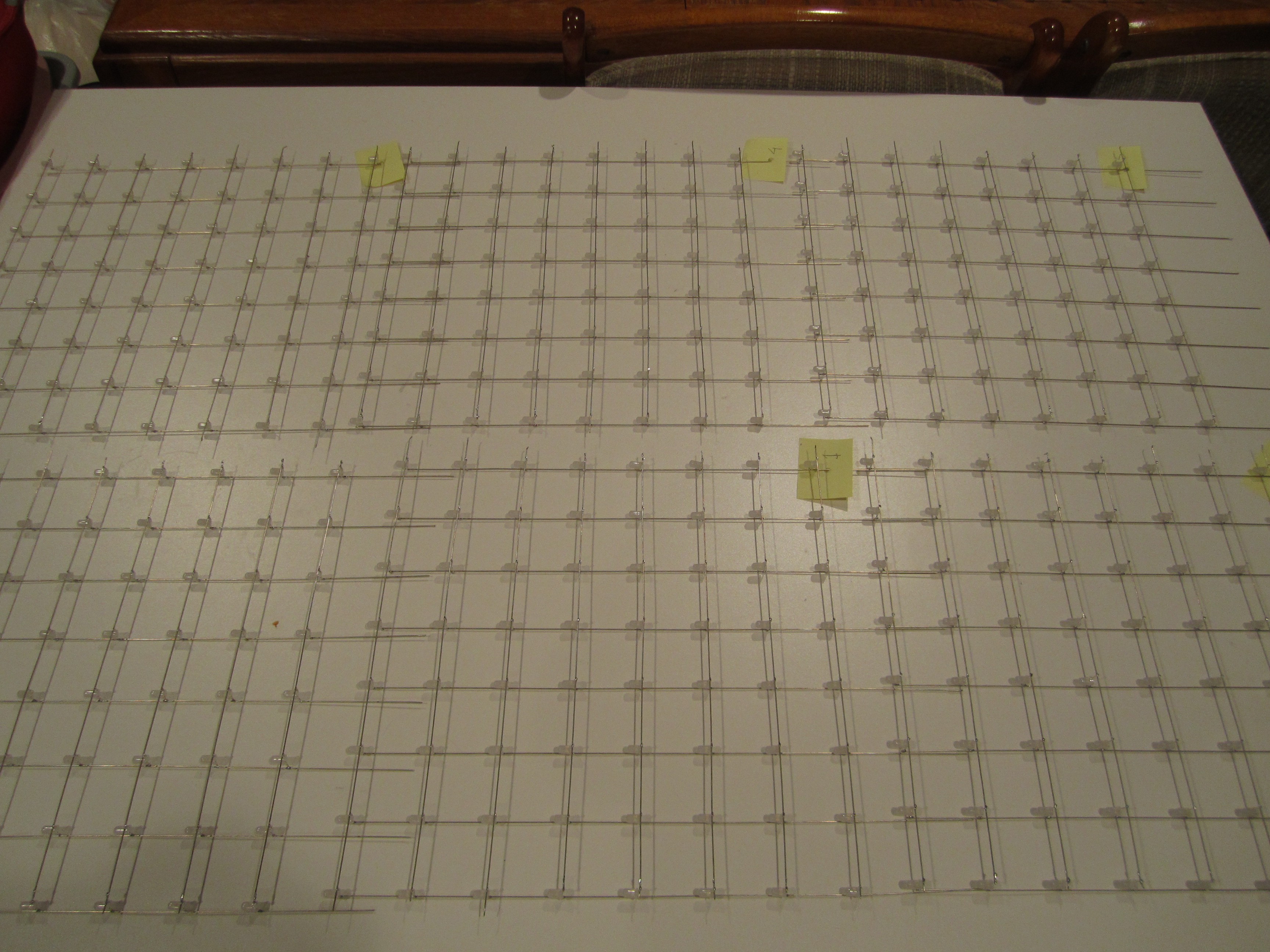
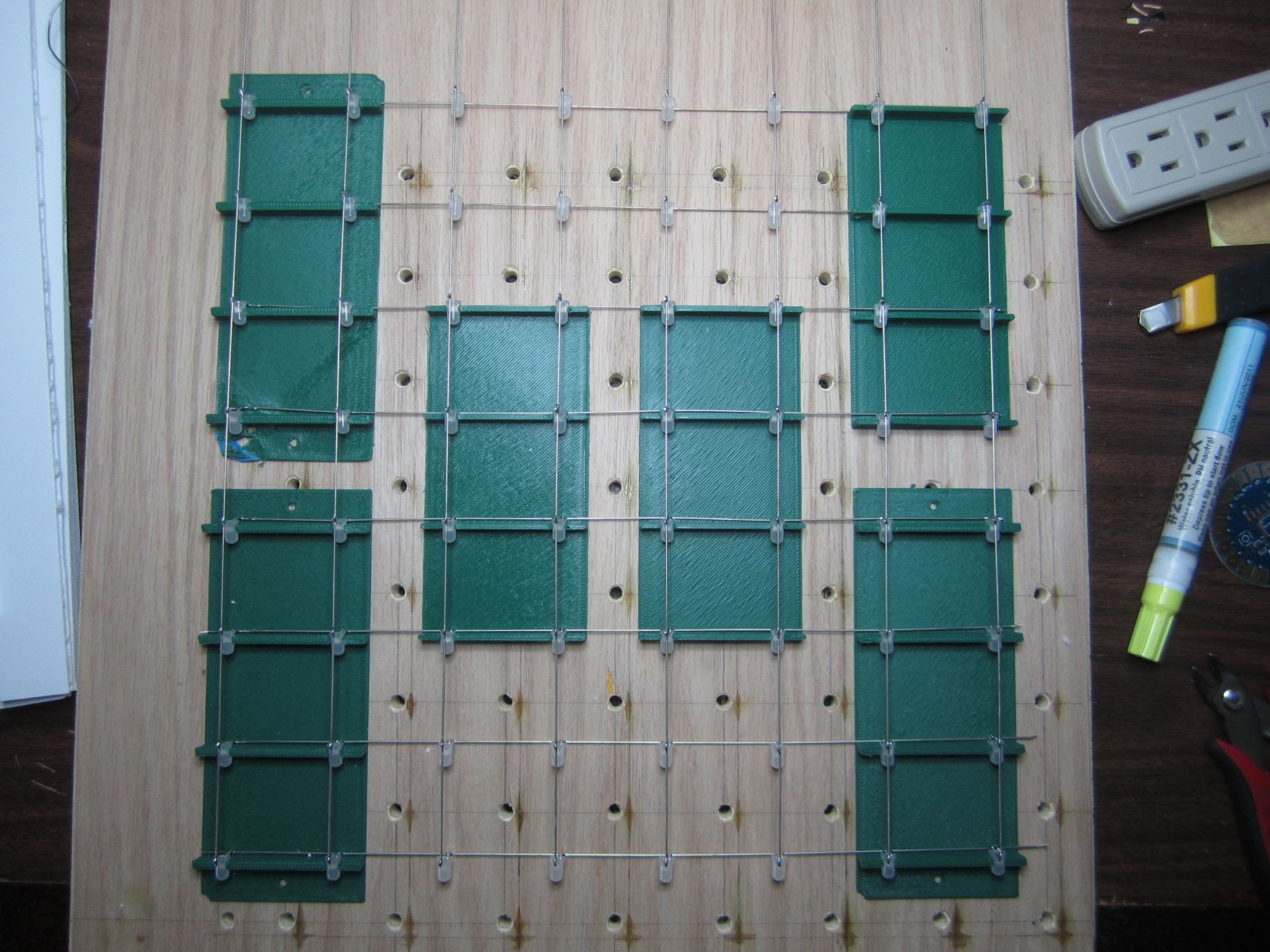
Halfway there?
06/24/2014 at 04:40 • 0 commentsThese are all 512 LEDs that will make up the cube. There will be eight vertical walls of 64 LEDs each. Two such walls have been completed. The other six walls still need to be soldered together (eight strands of eight LEDs each). Should go pretty quick now that I have the 3D printed jig.
![]()
-
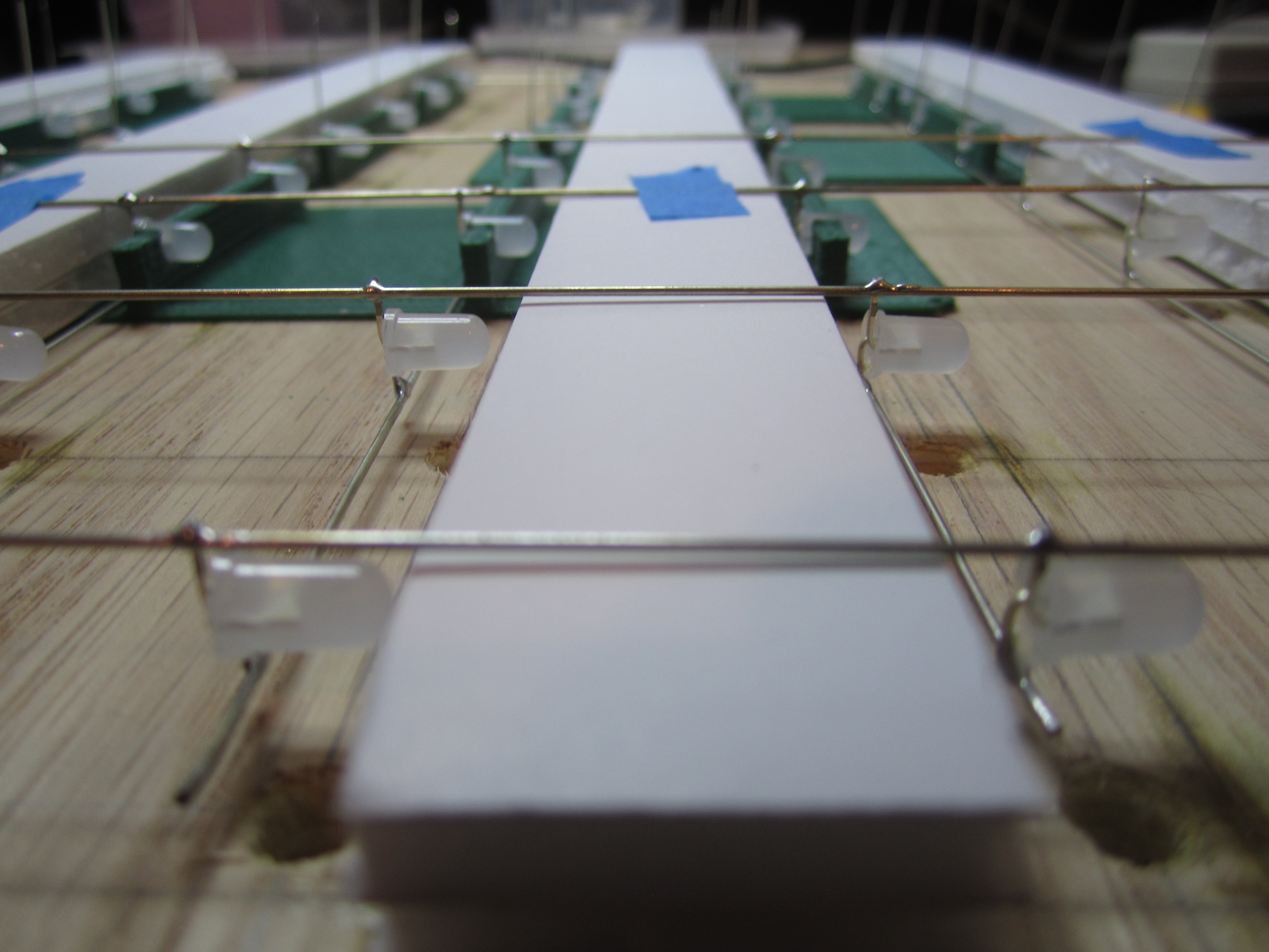
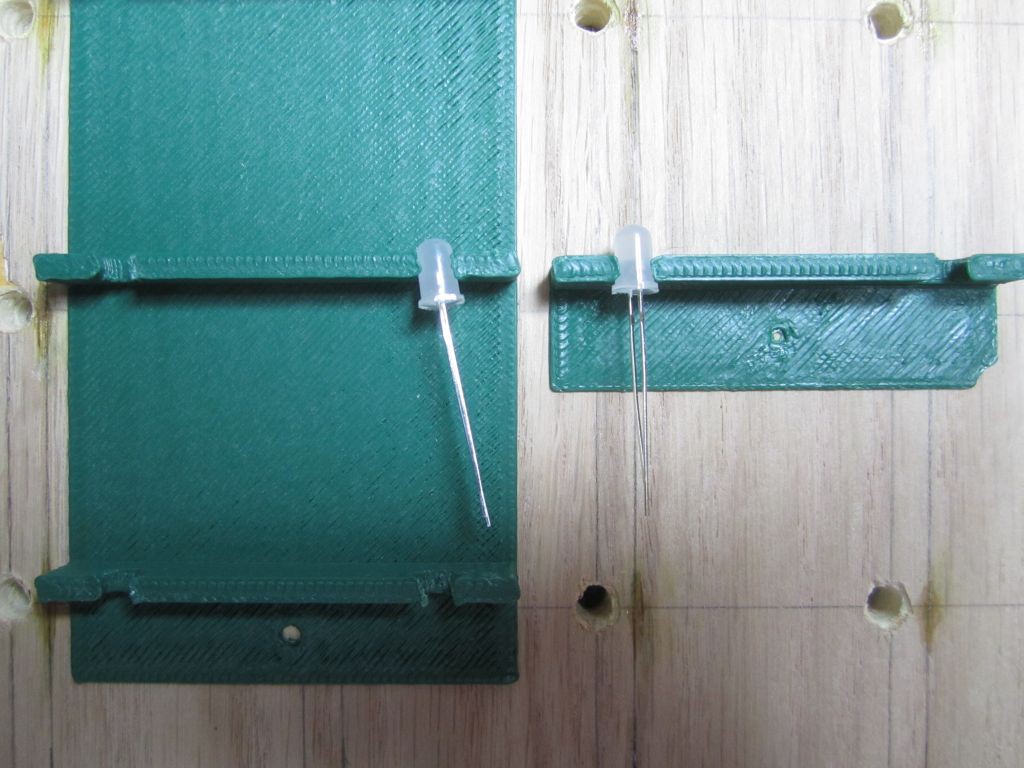
More jigs
06/22/2014 at 17:36 • 0 commentsI'm sure I'm making this harder than it needs to be, but it took several iterations to make the "vertical" jig.
I probably should make even more so I don't have to keep moving them as I solder.![]()
![]()
I got impatient and increased the print speed on my printer and that lowered the print quality. Note how the LED is held crooked. Thankfully, I was able to straighten it out by holding soldering iron near the trouble spot and correct the hole by inserting an LED to reform the hole.
![]()
With six jigs, the structure is finally rigid enough for soldering. Here's one finished wall. Horizontal wires are anodes that will be common per layer. Vertical wires are cathodes (eight per wall, 64 total). You can see the excess vertical wires at the top of this photo. These will elevate the lowest layer 4cm above the base, so the cube would appear to be floating rather than resting on the base.
![]()
-
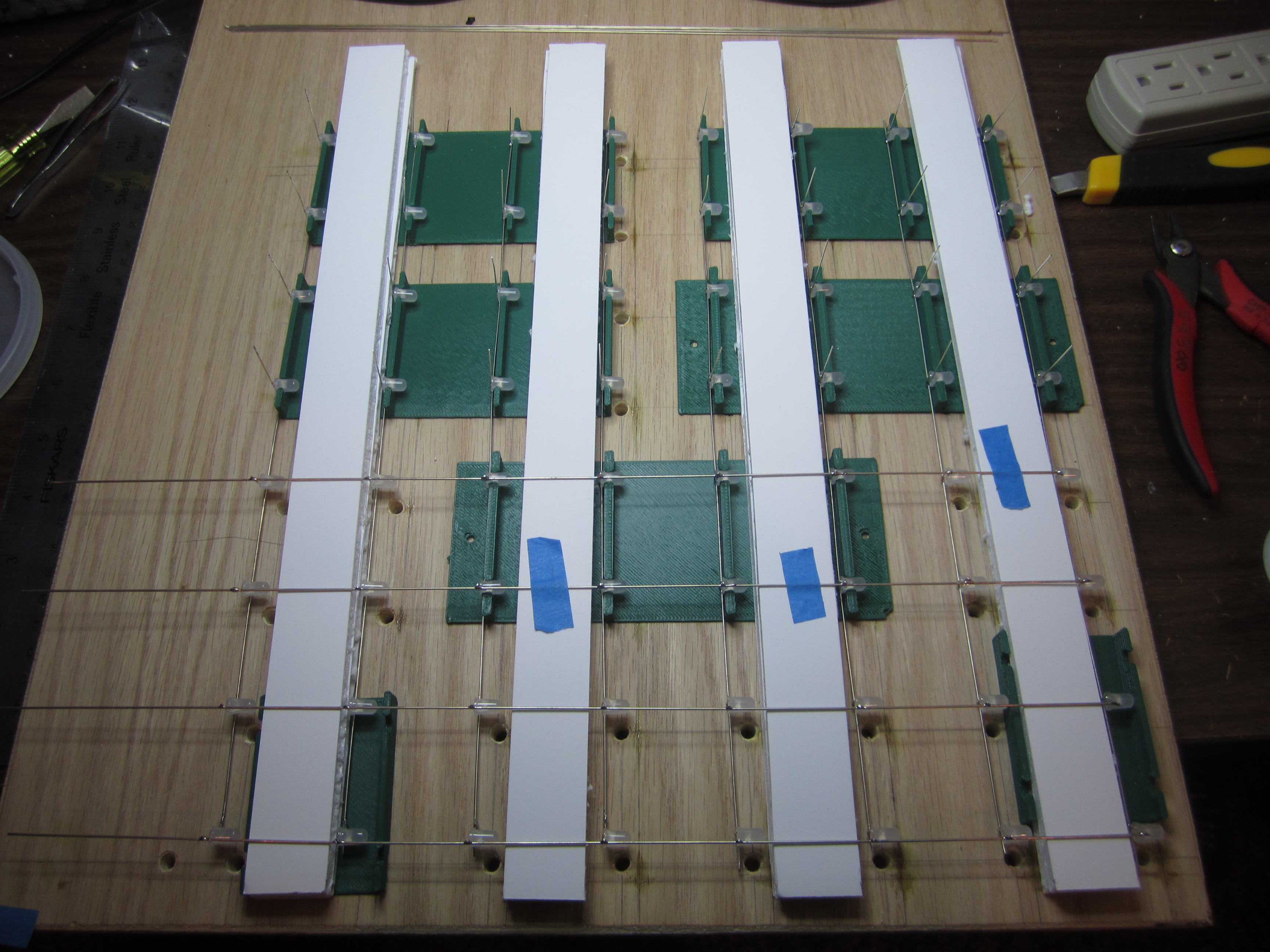
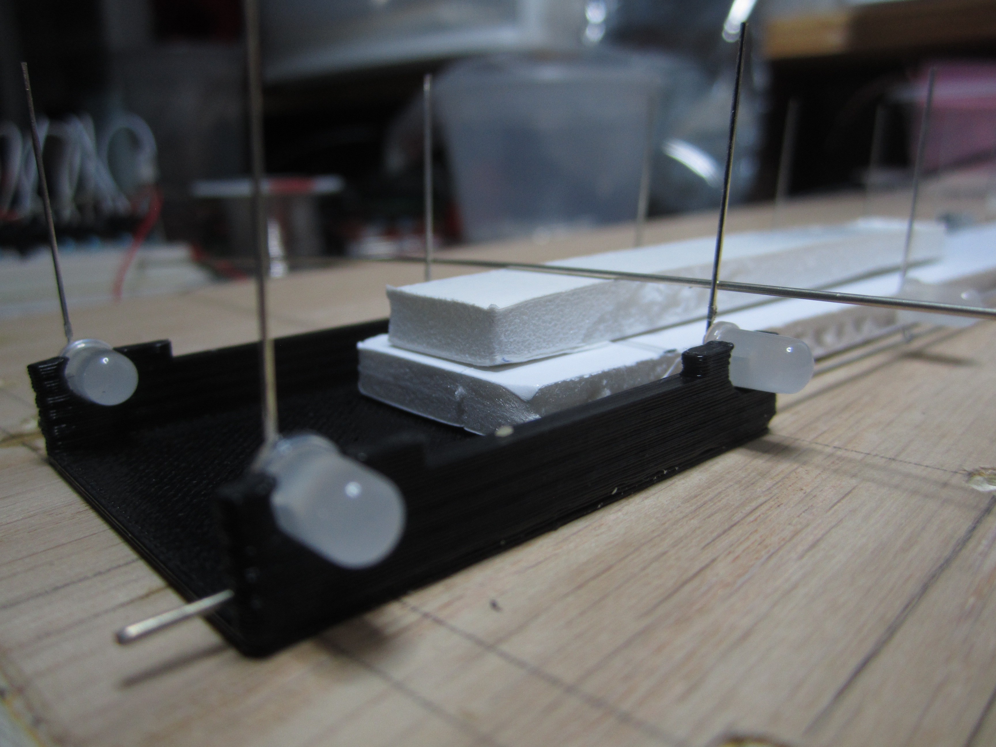
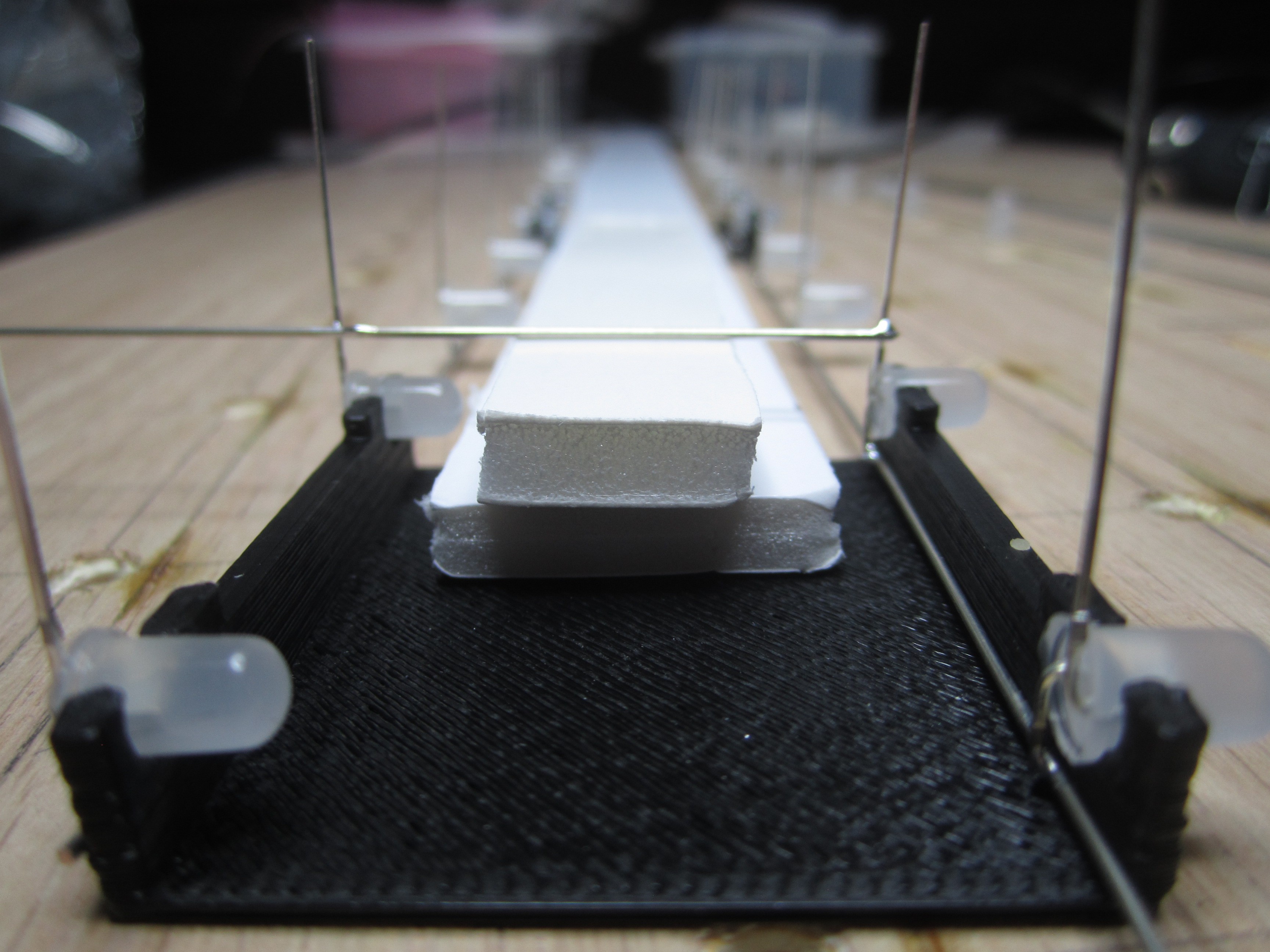
It's easier to do it when you're laying down
06/17/2014 at 05:32 • 0 commentsThanks to my fellow makers BrianM and TonyF for helping me solve the forest of 64 vertical wires! As you've seen from my previous updates, I've been soldering 64 LEDs as horizontal layers. This is a mistake!! Once I have all all eight layers, soldering in a forest of 64 vertical cathode wires would be very difficult if not impossible. I've seen others solve this by creating pillars or vertical walls of LEDs instead of horizontal layers of LEDs. The next problem is how to keep the vertical wires straight up while also keeping the LED rows lined up. BrianM came up with a brilliant solution! Lay them flat on the table! Although we're making a wall of LEDs, there is no reason why we can't lay them flat while we solder them. I made a jig using my 3D printer and as you can see, it works very well. I just need to print a few more so I can solder the whole wall at once without moving the jig.
![]()
![]()
8x8x8 Blue LED Cube
512 LEDs driven by an Arduino via eight shift-registers and eight MOSFETs