 Hari Wiguna
-
Soldering, soldering, and more soldering.
06/16/2014 at 05:39 • 0 comments![]()
![]()
![]()
![]()
-
Soldering 8x8 LED layers
06/15/2014 at 19:19 • 0 comments -
How to straighten thin wires
06/15/2014 at 19:18 • 0 comments -
1 Arduino, 64 individually controlled LEDs
06/13/2014 at 13:51 • 0 commentsLast night, I should have been soldering my cube. Instead, I decided to wire up all the circuit for one layer on six breadboards.
-
Eight down, 504 to go!
06/11/2014 at 01:57 • 1 commentI got the first eight LEDs soldered. I was initially concerned that animations might be too jerky because I spread out the LEDs too far apart. I think it will be ok.
-
Working circuit prototype
06/09/2014 at 01:10 • 1 comment -
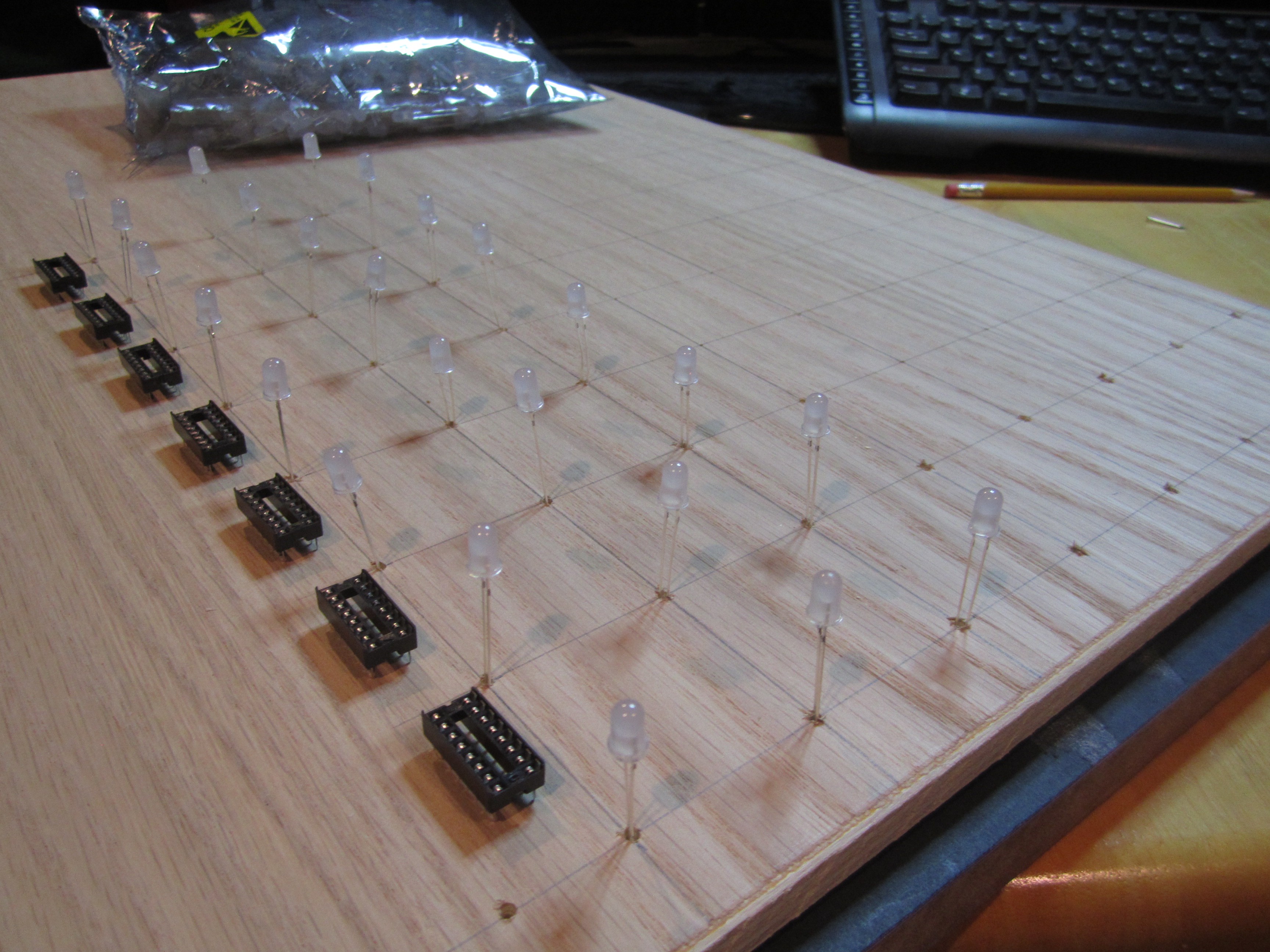
Template
06/09/2014 at 01:06 • 0 commentsAfter drawing the grid. I used a nail to mark the intersections where I need to drill. Then I drilled a small hole. Here is how I envision the shift registers would be mounted on the PCB that is the base of the cube.
![]()
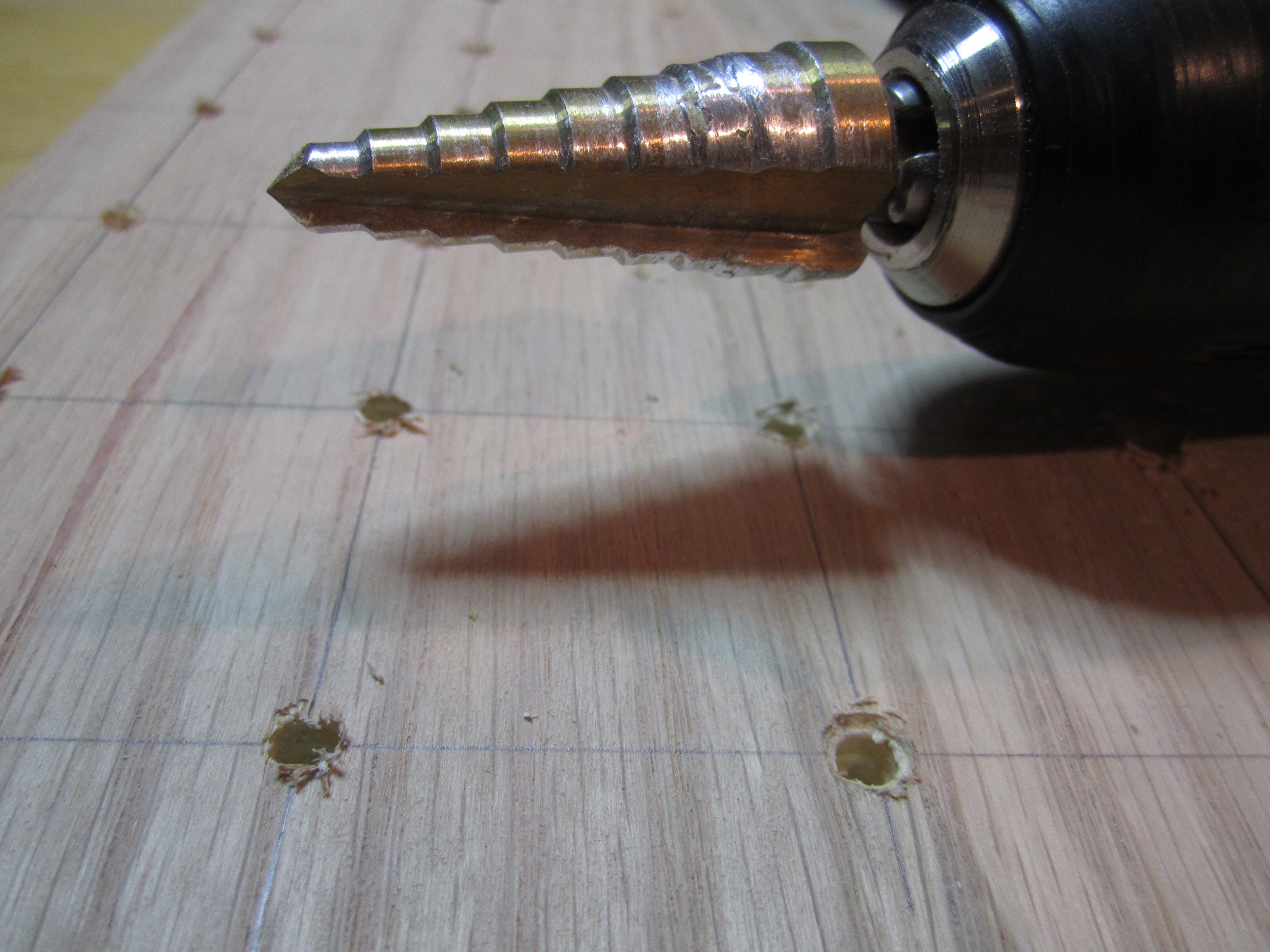
After drilling the hole to the same size as the LED, I used this drill bit to smooth out the rough edges. Left is before, right is after.
![]()
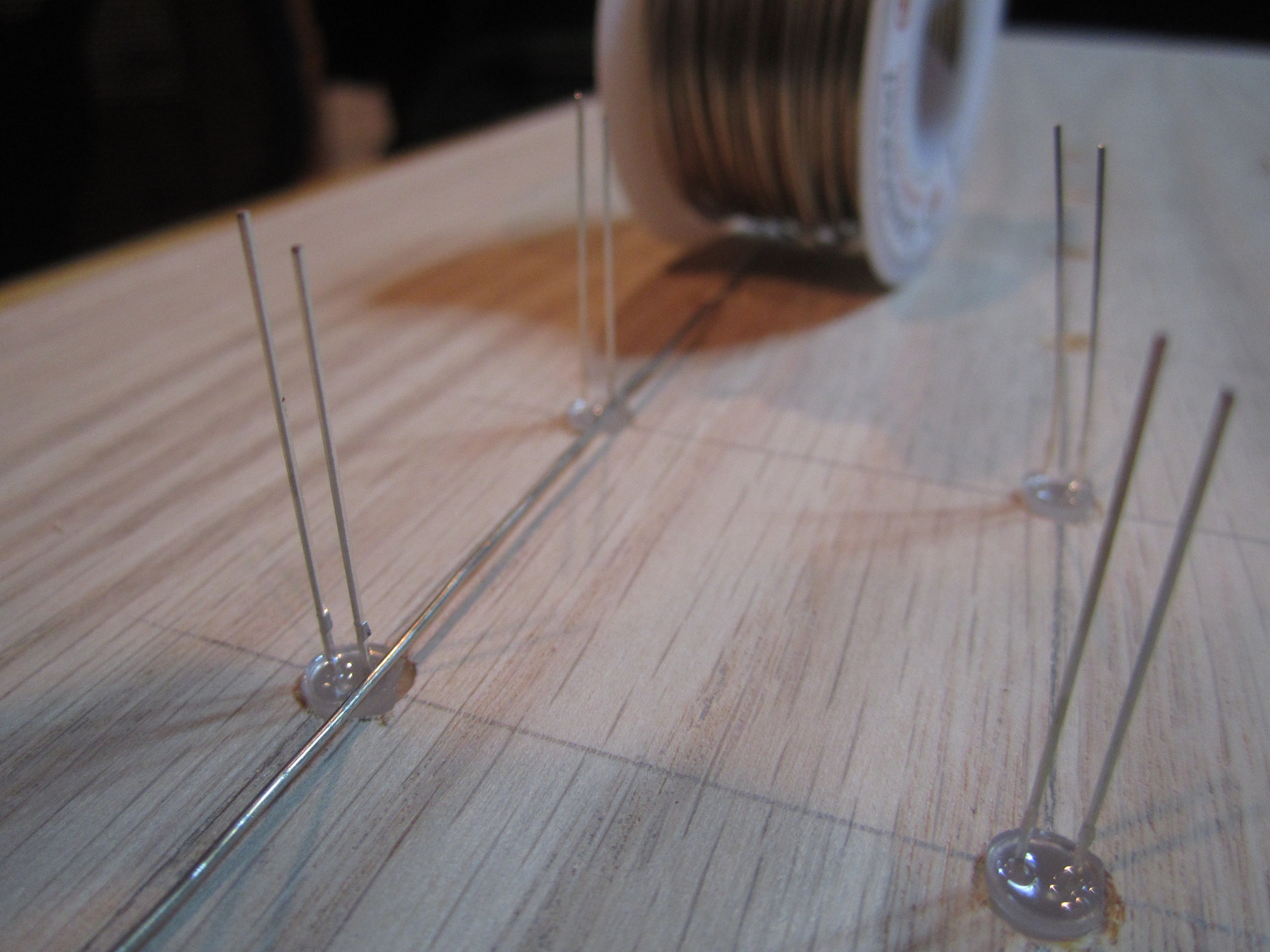
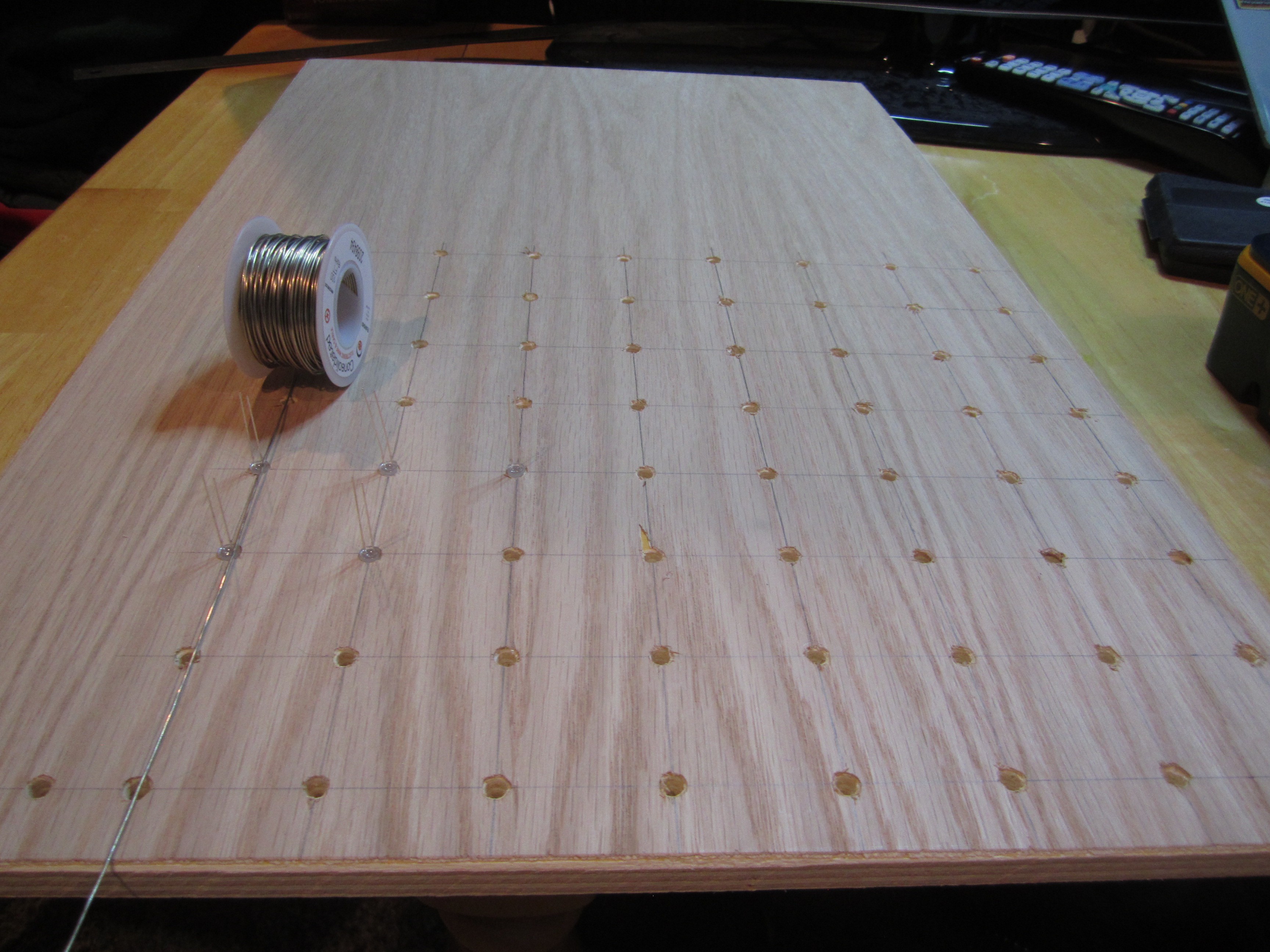
Still undecided where to bend the leads and solder them to the structural wires.
![]()
![]()
-
Perfect brightness, but more parts :-(
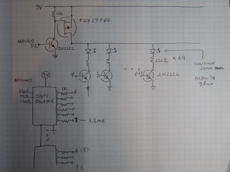
06/07/2014 at 16:03 • 0 commentsUPDATE 12/2014: I've posted a simpler circuit.
I've tested this circuit. The LED brightness is now awesome. LEDs are getting almost 10ma even when pulsed.
However, it seems like an unnecesarily complicated circuit. Any thoughts on making it simpler?The transistor driving the MOSFET gate is necessary because 5V from the Arduino weren't sufficient to drive the gate.
64 more transistors are necessary to drive the LED cathodes because without them, the LEDs were always on regardless of the bit value on the shift register output. When the bit is low, the LED is brighter, when the bit is high (5V), the LED is dim, but not off. I think it's because there's still 4V difference between the LED cathode and anodes.
![]()
-
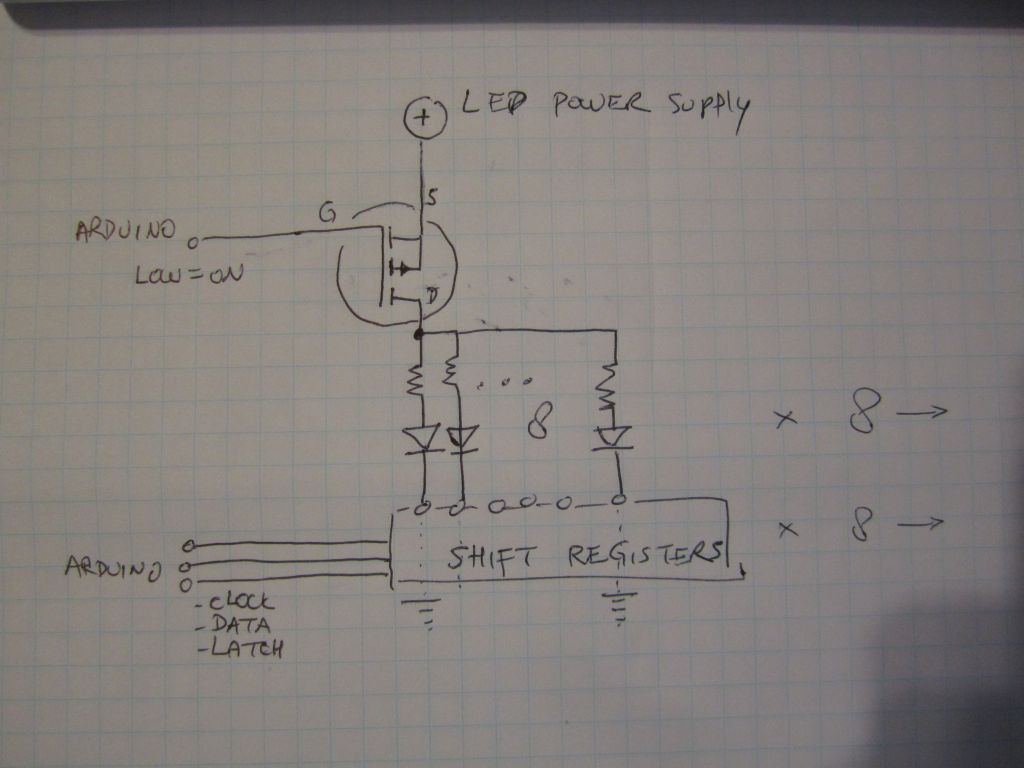
Need someone brighter than me to add brightness to my LEDs
06/05/2014 at 01:37 • 0 comments![]()
This works but because the MOSFET is only on 1/8th of the time, the LEDs are too dim for my liking. Turning the LED PSU up from 5V to 9V helps, but I worry that if the MOSFET ever stop pulsing, then I'd burn those LEDs. Resistors are 100 ohm. Shift registers are 74HC595, MOSFET is p-channel (FQP27P06). There must be a better way... Current limiting circuit for safety? How?
-
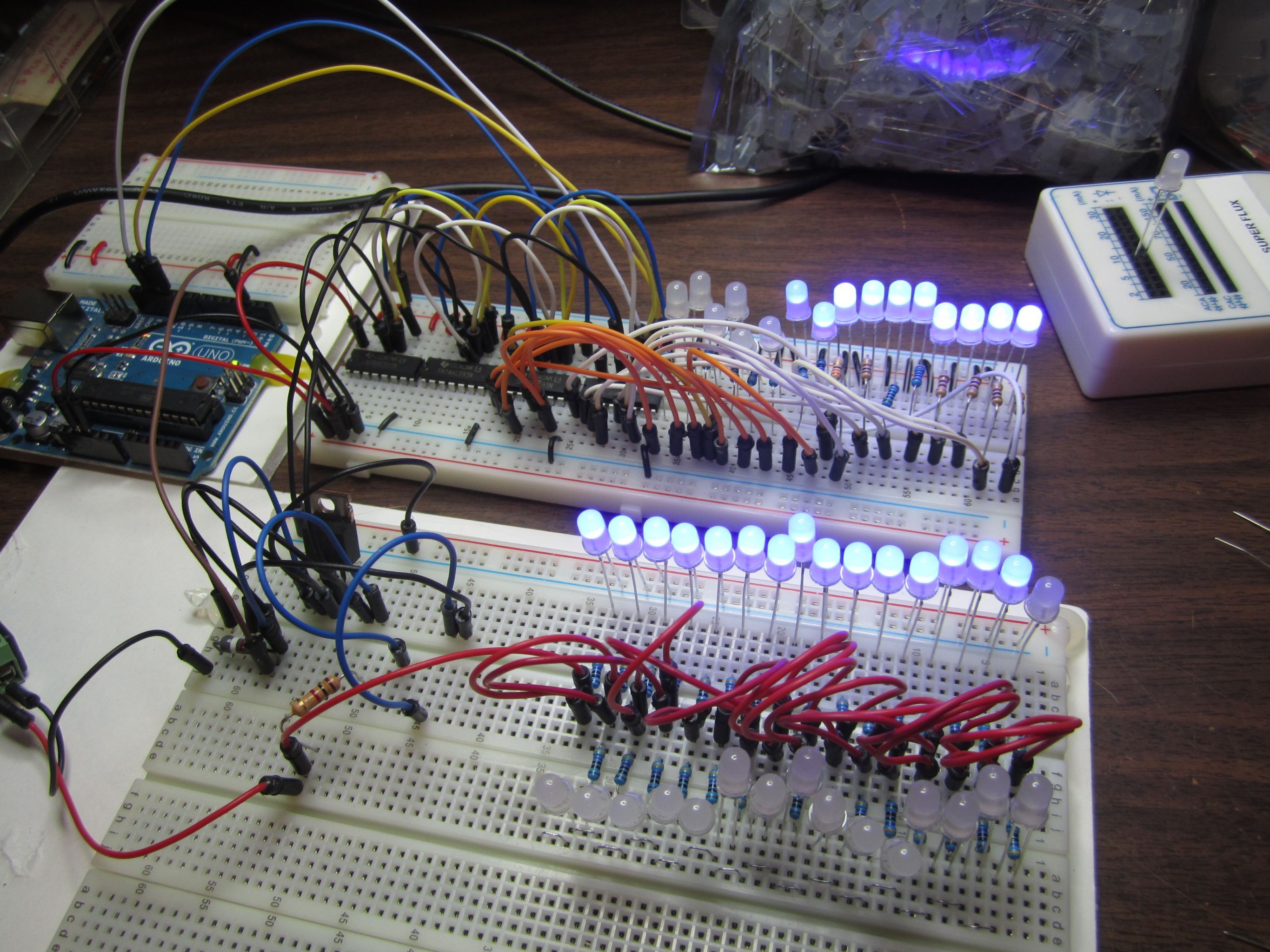
Practice Run
06/02/2014 at 05:53 • 0 commentsBefore soldering the cube, I want to make sure that it will work as expected, so I wired up as much as I can on a breadboard to do a practice run:
In the foreground breadboard I'm testing the different transistors to drive the cathode of all 64 LEDs that's on a layer. I only wired up 32 to get an idea of current that the transistor has to deal with. I tested three different transistors to drive the LED cathodes and liked the MOSFET the best.
In the background breadboard I'm testing the shift registers. I only have four shift-registers on hand, so that's what I wired up.
Although the LEDs look very bright in the photo below. In real life they're not that brightly lit. They're dim because we'll have eight layers with unique cathodes, but all the layers share the same 64 anodes. So each layer is only lit 1/8th of the time. I've lowered the LED resistors down to 100 ohm, I don't dare go lower in case they're ever lit without any pulsing.
My multimeter shows that each LED is only consuming 2mA. I think its confused by the pulsing.
![]()
8x8x8 Blue LED Cube
512 LEDs driven by an Arduino via eight shift-registers and eight MOSFETs