AndrewMcDan
-
Climate Control Controller Complete
04/20/2018 at 14:09 • 0 commentsI've spent the past couple days working various parts of this project, and I have completed the controller for the climate control system.
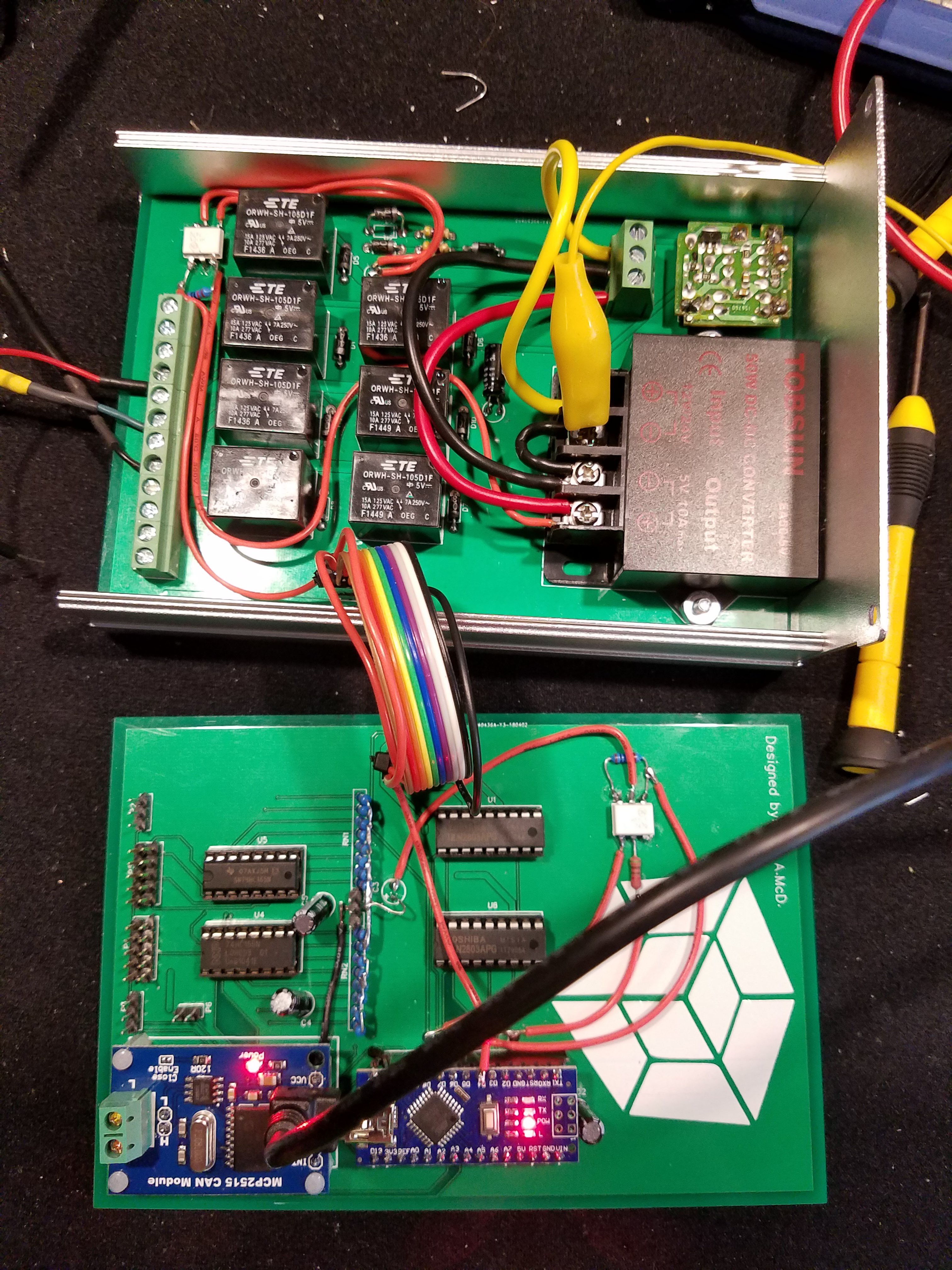
![]()
Relays for controlling the fan, 5V DC-DC switched power supply, timer circuit from the original rear-window-defrost, CAN-bus controller, and an Arduino. The headers on the left of the bottom board are for the servos and encoders that interface with the OEM push-pull cable system.
Here's the code for the Arduino:
#include <Servo.h>
#include <mcp_can.h>
#include <SPI.h>
#include <EEPROM.h>


#define CAN_INT 2
#define AC_STATUS 5
#define SERVO_2 6
#define SERVO_1 7
#define LOAD_DATA 8
#define CLK_INH 9
#define CAL_BTN 3
#define FAN_SET1 A0
#define FAN_SET2 A1
#define FAN_SET3 A2
#define FAN_SET4 A3
#define DEF_TOG A4
#define AC_EN A5
#define RECIRC_EN A6
#define AC_STATUS_ANALOG A7
#define DEF_STATUS 4


MCP_CAN CAN0(10);
bool CANgood = false, def_toggle = false, AC_enable = false, recirc_enable = false;
long unsigned int rxId;
unsigned char len = 0;
unsigned char rxBuf[4], txBuf[4];
Servo servo1, servo2;
unsigned int encoders1 = 0, encoders2 = 0;
int numberOfPositions_1 = 0, numberOfPositions_2 = 0;
byte fans = 0, temp_1 = 0, destination = 0;
unsigned long time = 0,time2=0;

void setup() {
  Serial.begin(115200);
  pinMode(CAN_INT, INPUT);
  pinMode(AC_STATUS, INPUT);
  pinMode(DEF_STATUS, INPUT);
  pinMode(SERVO_2, OUTPUT);
  pinMode(SERVO_1, OUTPUT);
  pinMode(LOAD_DATA, OUTPUT);
  pinMode(CLK_INH, OUTPUT);
  pinMode(CAL_BTN, INPUT_PULLUP);
  pinMode(FAN_SET1, OUTPUT);
  pinMode(FAN_SET2, OUTPUT);
  pinMode(FAN_SET3, OUTPUT);
  pinMode(FAN_SET4, OUTPUT);
  pinMode(DEF_TOG, OUTPUT);
  pinMode(AC_EN, OUTPUT);
  pinMode(RECIRC_EN, OUTPUT);

  digitalWrite(FAN_SET1, LOW);
  digitalWrite(FAN_SET2, LOW);
  digitalWrite(FAN_SET3, LOW);
  digitalWrite(FAN_SET4, LOW);
  digitalWrite(RECIRC_EN, LOW);
  digitalWrite(AC_EN, LOW);
  digitalWrite(DEF_TOG, LOW);
  digitalWrite(CLK_INH, HIGH);
  digitalWrite(LOAD_DATA, HIGH);
  //digitalWrite(CAL_BTN, HIGH);

  servo1.attach(SERVO_1);
  servo2.attach(SERVO_2);


  if (CAN0.begin(CAN_1000KBPS) == CAN_OK) {
    CAN0.init_Mask(0, 0, 0x7Ff);
    CAN0.init_Mask(1, 0, 0x7ff);
    CAN0.init_Filt(0, 0, 0x00e); // climate control data
    CAN0.init_Filt(2, 0, 0x00e);
    CAN0.init_Filt(3, 0, 0x00e);
    CAN0.init_Filt(4, 0, 0x00e);
    CAN0.init_Filt(5, 0, 0x00e);
    Serial.print("can init ok!!\r\n");
    CANgood = true;
  }
  else {
    Serial.println("not ok");
    //while (true) {}
    Serial.println("continuing");
  }


  if (!digitalRead(CAL_BTN)) {
    Serial.println("calibration");
    calibrateEncoders();
  }
  for (int i = 0; i < 4; i++) {
    txBuf[i] = 0;
  }
}

void loop() {
  // every 500 ms, send an update to the main controller
  if ((millis() - time) > 500) {
    time = millis();
    txBuf[0] = txBuf[0] | fans;
    txBuf[0] = txBuf[0] | (def_toggle << 4);
    txBuf[0] = txBuf[0] | (AC_enable << 5);
    txBuf[0] = txBuf[0] | (recirc_enable << 6);
    txBuf[1] = temp_1;
    txBuf[2] = destination;
    txBuf[3] = analogRead(AC_STATUS_ANALOG)>300?1:0 | (digitalRead(DEF_STATUS) << 1);
    CAN0.sendMsgBuf(0x7ff, 0, 4, txBuf);
    Serial.print("AC status: ");
    Serial.println(digitalRead(AC_STATUS));
    Serial.print("Defroster Status: ");
    Serial.println(digitalRead(DEF_STATUS));
    Serial.println("");
  }

  // This is here for testing purposes
  /*if((millis()-time2)>5000){
    time2=millis();
    //def_toggle = true;
    recirc_enable = !recirc_enable;
    AC_enable = !AC_enable;

    if(fans==16){
      fans=0;
    }else if(fans==0){
      fans=1;
    }else{
      fans = fans << 1;
    }
  }*/

  // If the CAN bus has new data for this controller, read it an do stuff with the data
  if (!digitalRead(CAN_INT) && CANgood) {
    CAN0.readMsgBuf(&len, rxBuf);
    rxId = CAN0.getCanId();
    if ((rxId == 0x00e) && (len >= 3)) {
      fans = rxBuf[0] & B00001111;
      def_toggle = rxBuf[0] & B00010000;
      AC_enable =  rxBuf[0] & B00100000;
      recirc_enable = rxBuf[0] & B01000000;
      temp_1 = rxBuf[1];
      destination = rxBuf[2];
    }
  }

  // we only want to turn on one of the fan signals at a time, so check to make sure that only one bit is set high or all are low
  if (countSetBits(fans) <= 1) {
    digitalWrite(FAN_SET1, fans & B00000001);
    digitalWrite(FAN_SET2, fans & B00000010);
    digitalWrite(FAN_SET3, fans & B00000100);
    digitalWrite(FAN_SET4, fans & B00001000);
  }

  // send a pulse to the defrost timer
  if (def_toggle) {
    digitalWrite(DEF_TOG, HIGH);
    delay(200);
    digitalWrite(DEF_TOG, LOW);
    def_toggle = false;
  }

  digitalWrite(AC_EN, AC_enable);
  digitalWrite(RECIRC_EN, recirc_enable);
  updateServos(temp_1 , destination );
}

bool updateServos(byte servo_1_pos, byte servo_2_pos)
{


  // A lot goes on in the next few lines of code
  // starting with new position variables and working outwards:
  // these two variables are in the range of 0 to 255 so lets map it to a new range.
  // the new range is from 0 to whatever the caliration set as the max position.
  // the calibration set the max position in EEPROM in the last two addresses.
  // once the mapping is complete, we read the current encoder data and use that as the address
  // to look up what the current position is.
  // to make sure we are working with good values, lets contrain this position values that are
  // between 0 and the max position as read from the last two addresses in EEPROM.
  // subtract our mapped int from the current position to get our offset.
  // multiply this offset by 10 so that the servo speed will be quick.
  // constrain maximum servo speed to +/-30.
  // add 90 because that is the "stop" speed.
  // write to the servo.


  byte len = EEPROM[EEPROM.length() - 1] - 2; // stay 2 positions away from edge
  byte currentPos = EEPROM[highByte(read74HC165())];
  if (currentPos != 255) { // check for out of bounds value (255) prior to updating servo
    servo1.write(
      constrain(
        (
          currentPos
          - map(
            servo_1_pos, 0, 255, 2, len // stay 2 positions away from edge
          )
        ) * 10 , -30, 30
      ) + 90
    );
  } else {
    return false; // hit out of bounds
  }
  len = EEPROM[EEPROM.length() - 2] - 2;
  currentPos = EEPROM[lowByte(read74HC165())];
  if (currentPos != 255) {
    servo2.write(
      constrain(
        (
          currentPos
          - map(
            servo_2_pos, 0, 255, 2, len
          )
        ) * 10 , -30, 30
      ) + 90
    );
  } else {
    return false;
  }
  return true;
}


//======================================================================
// Reads two bytes from the 74HC165 registers
unsigned int read74HC165()
{
  digitalWrite (LOAD_DATA, LOW);        //load the push button state into the 74HC165
  asm("nop\n nop\n");              //some delay
  digitalWrite (LOAD_DATA, HIGH);
  digitalWrite (CLK_INH, LOW);        //enable 74HC165 clock
  asm("nop\n nop\n");              //some delay
  unsigned int Switches = SPI.transfer16(0); //get the position
  digitalWrite (CLK_INH, HIGH);       //disable 74HC165 clock

  return  Switches;                //switches will have the value read by then 74HC165
}
//       END of read74HC165()
//======================================================================


void calibrateEncoders() {
  for (int i = 0 ; i < EEPROM.length() ; i++) {
    EEPROM.write(i, 255);
  }

  while (!digitalRead(CAL_BTN)) {}
  Serial.println("Starting Clibration of number 1.");
  Serial.println("Press button when reaching start point.");
  delay(2000);
  servo1.write(100);
  while (digitalRead(CAL_BTN)) {}
  servo1.write(90);
  Serial.println("end position noted");
  byte encoder_1 = highByte(read74HC165());
  byte encoder_2 = encoder_1;
  int pos = 0;
  delay(2000);
  Serial.println("Other direction");
  delay(1000);
  servo1.write(80);
  while (digitalRead(CAL_BTN)) {
    int tester = countSetBits(encoder_1 ^ encoder_2);
    if (tester > 1) {
      Serial.println(tester);
    }
    if ((tester == 1) && (EEPROM[encoder_1] != EEPROM[encoder_2])) {
      //Serial.println(encoder_1, BIN);
      //Serial.println(pos);
      servo1.write(90);
      delay(5);
      EEPROM[ encoder_1 ] = pos;
      encoder_2 = encoder_1;
      pos++;
      delay(5);
      servo1.write(80);
    }
    encoder_1 = highByte(read74HC165());
  }
  servo1.write(90);
  EEPROM[ EEPROM.length() - 1 ] = --pos;


  while (!digitalRead(CAL_BTN)) {}
  Serial.println("Starting Clibration of number 2.");
  Serial.println("Press button when reaching start point.");
  delay(2000);
  servo2.write(100);
  while (digitalRead(CAL_BTN)) {}
  servo2.write(90);
  Serial.println("end position noted");
  encoder_1 = lowByte(read74HC165());
  encoder_2 = encoder_1;
  pos = 0;
  delay(2000);
  Serial.println("Other direction");
  delay(1000);
  servo2.write(80);
  while (digitalRead(CAL_BTN)) {
    int tester = countSetBits(encoder_1 ^ encoder_2);
    if (tester > 1) {
      Serial.println(tester);
    }
    if ((tester == 1) && (EEPROM[encoder_1 + 512] != EEPROM[encoder_2 + 512])) {
      //Serial.println(encoder_1, BIN);
      //Serial.println(pos);
      servo2.write(90);
      delay(5);
      EEPROM[ encoder_1 + 512 ] = pos;
      encoder_2 = encoder_1;
      pos++;
      delay(5);
      servo2.write(80);
    }
    encoder_1 = lowByte(read74HC165());
  }
  servo2.write(90);
  EEPROM[ EEPROM.length() - 2 ] = --pos;
  Serial.println("test");
  time = millis();
  while ((millis() - time) < 10000) {
    updateServos(1, 1);
  }
  Serial.println("test1");
  time = millis();
  while ((millis() - time) < 10000) {
    updateServos(254, 254);
  }
  Serial.println("test2");
  delay(1000);
}

unsigned int countSetBits(int n)
{
  unsigned int count = 0;
  while (n)
  {
    n &= (n - 1) ;
    count++;
  }
  return count;
}
Schematics for this little gizmo can be found here :
https://easyeda.com/andrewmcdan/encoder-servo-controller (This board has the Arduino on it.)
https://easyeda.com/andrewmcdan/Encoder-Breakout
https://easyeda.com/andrewmcdan/encoder-servo-controller-2 (This board has the relays on it.)
More updates to come!
-
Let's simplify some things
04/01/2018 at 12:11 • 0 commentsI've been working on this project for about 4 years now, and havent made any noticeable progress. So I've decided to simplify the project a bit.
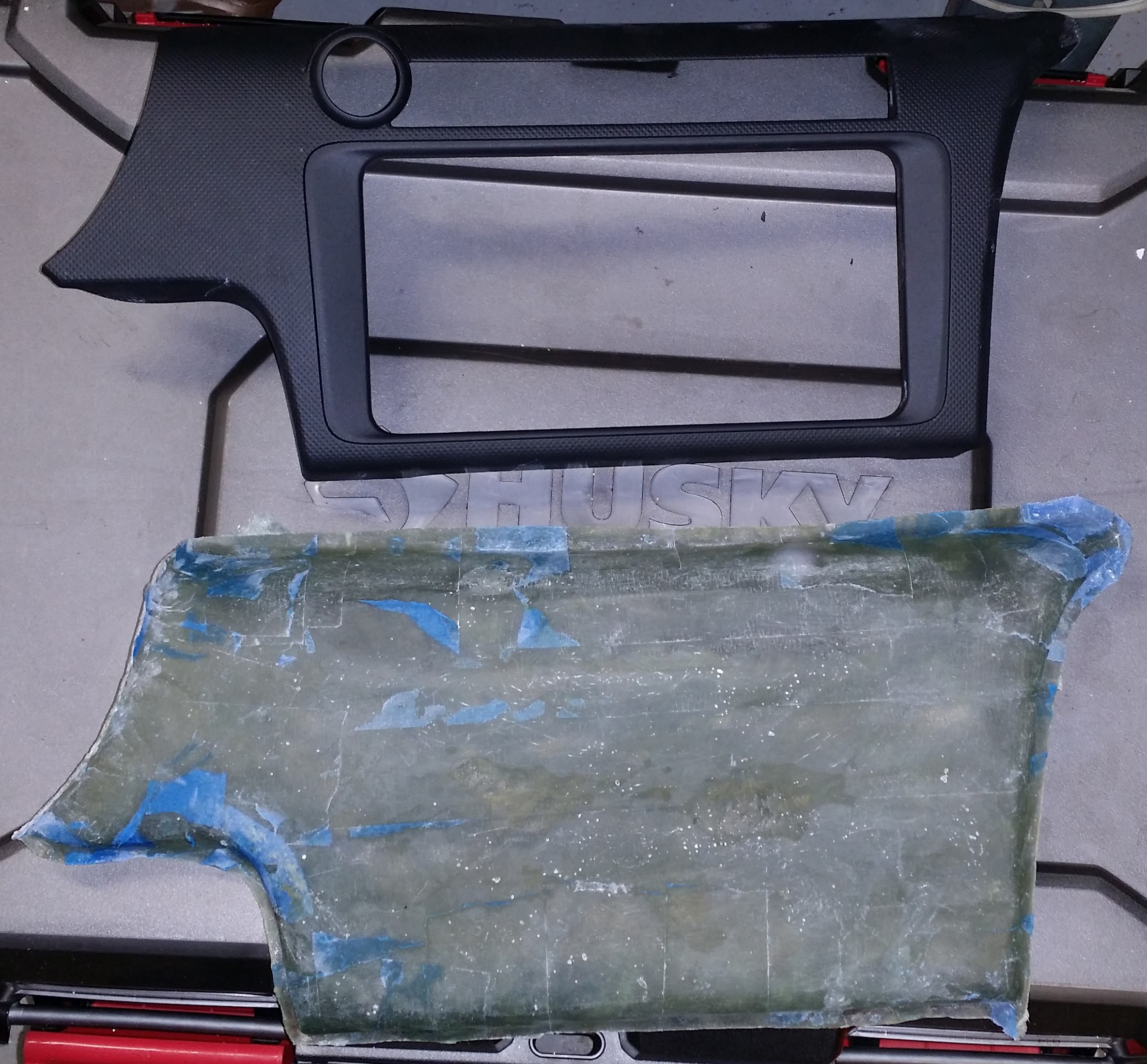
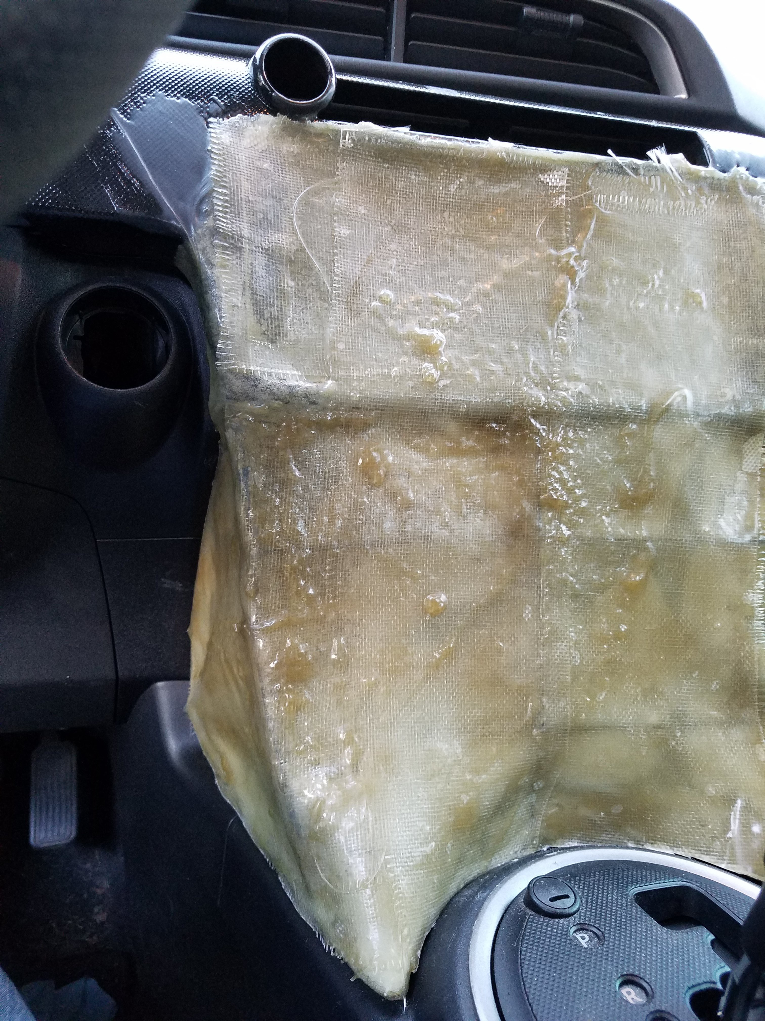
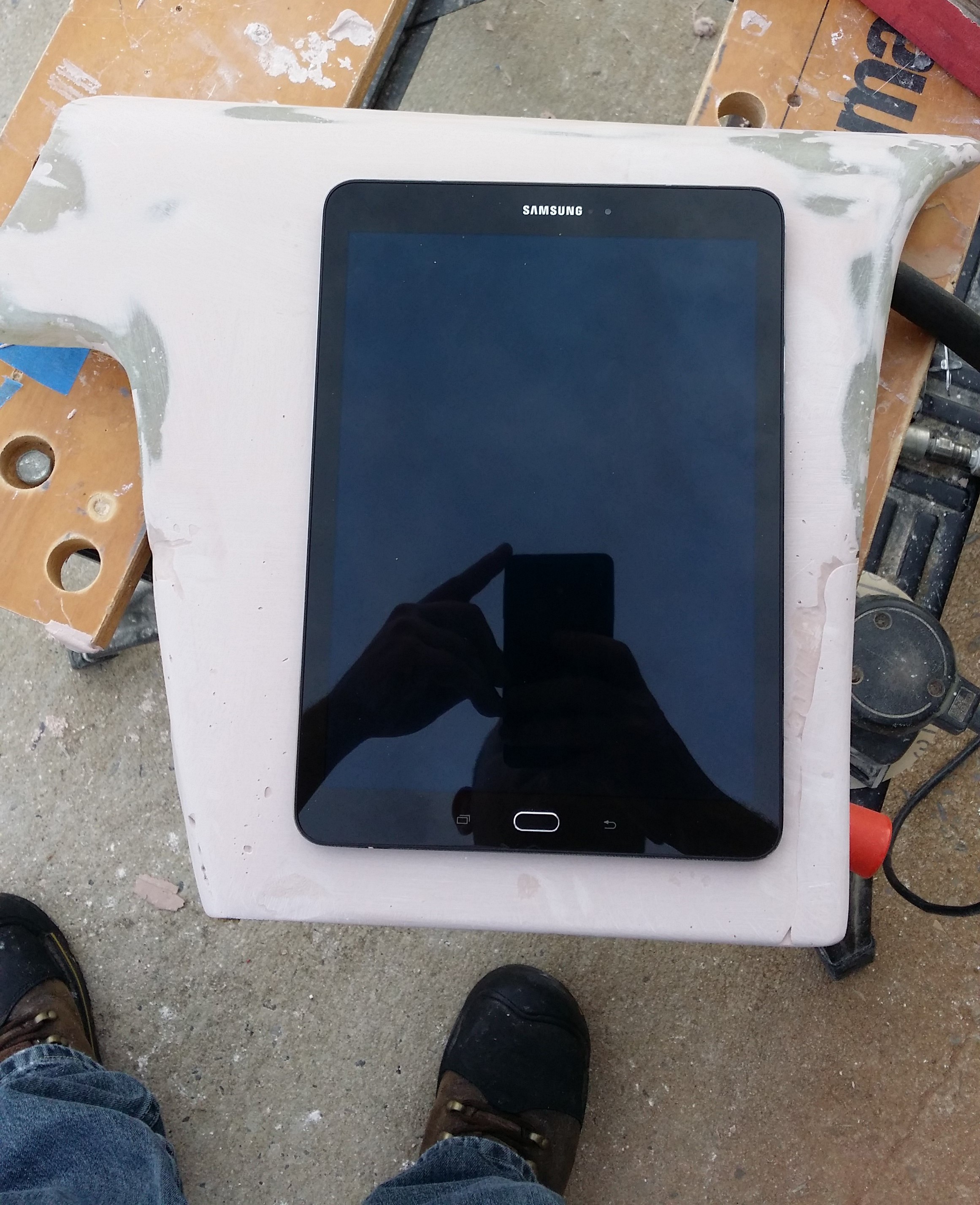
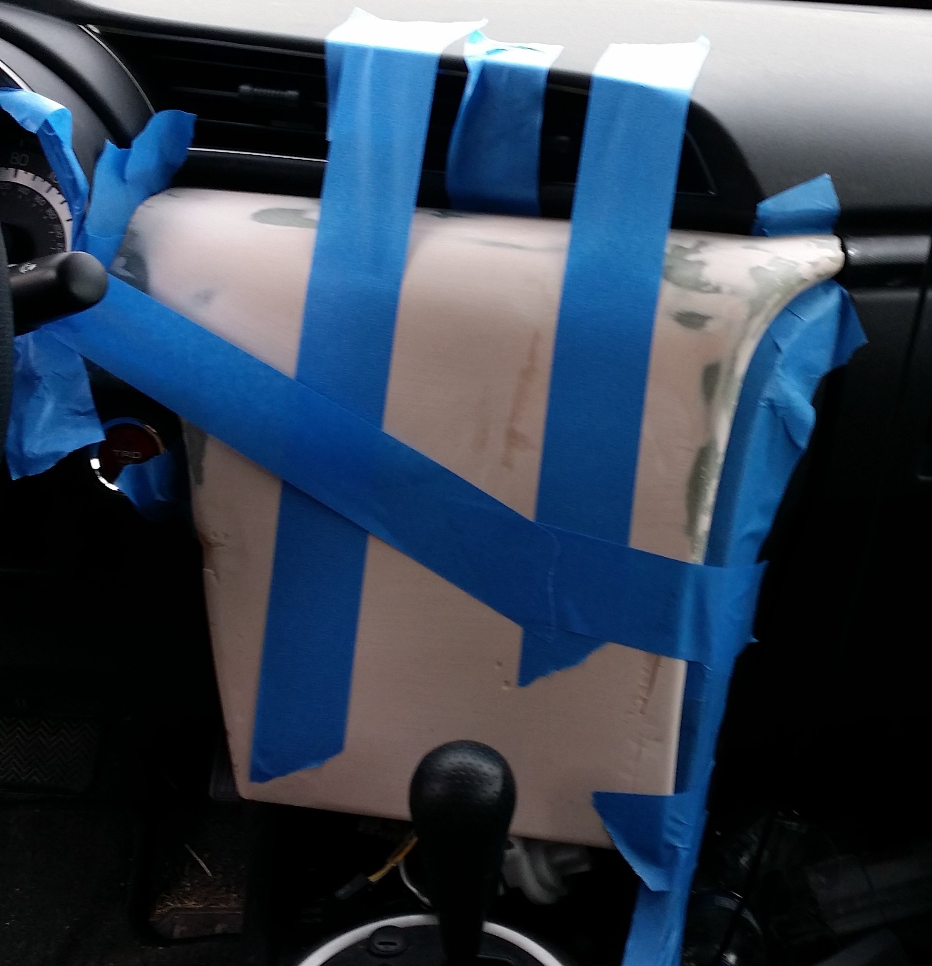
First, I've rethought how I'm going to mount the screen in my dash. Instead of popping a mold, modifying it, and casting a whole new dash bezel, im going to use the original part and modify it with fiberglass. The solves several problems, e.g. mounting, fitting, steps involved, types of materials needed, etc.
Secondly, I will not be mounting an Android tablet in the dash, and instead I will be installing an LCD connected to the RasPi.
Lastly, audio will be simple Bluetooth audio that feeds the amplifier instead of a USB interface connected to the tablet.
I've already made progress on the fiberglass work.
![]()
It's a little rough at the moment, but I'm working on it. I'll writeup another post on how I made the dash piece once it is complete.
Hopefully with the project being a bit less complicated I'll be able to make real progress on it in the coming months.
-
Volume Controller Code
05/28/2016 at 21:27 • 0 commentsCode for the volume controller is complete. Pretty simple stuff. Find it on GitHub here.
Here's a breakdown of code:
To start, include some libraries, declare some globals. The byte-sized variables are the I2C addresses for the digital potentiometers.
#include <Wire.h>
#include <mcp_can.h>
#include <SPI.h>

long unsigned int rxId;
unsigned char len = 0;
unsigned char rxBuf[8];

MCP_CAN CAN0(9);

byte addr_MSTR_L = B0111100, addr_MSTR_R = B0111110, addr_SUBW_L = B0111101, addr_SUBW_R = B0111111;
setup() is pretty simple too. Start up the Wire library, set our "interrupt" pin for the MCP2515 as input. The CAN bus controller I'm using is a MCP2515 which has interrupt capability when it receives data on the bus that matches the filter. I'm just gonna poll this pin rather than setup and actual interrupt. After starting up the CAN library at 500kbps, we set the receive masks and filters so that we only get messages sent to device ID 0x00F.void setup() { Wire.begin(); pinMode(8, INPUT); CAN0.begin(CAN_500KBPS); CAN0.init_Mask(0, 0, 0x7ff); CAN0.init_Mask(1, 0, 0x7ff); CAN0.init_Filt(0, 0, 0x00f); CAN0.init_Filt(1, 0, 0x00f); CAN0.init_Filt(2, 0, 0x00f); CAN0.init_Filt(3, 0, 0x00f); CAN0.init_Filt(4, 0, 0x00f); CAN0.init_Filt(5, 0, 0x00f); }The loop() runs without doing much unless the "interrupt" pin is driven low, in which case we read the data from the CAN bus and send each byte to its corresponding digital pot.void loop() { // check for CAN bus interrupt // if interrupt, read data and store, set new flag if (!digitalRead(8)) { CAN0.readMsgBuf(&len, rxBuf); Wire.beginTransmission(addr_MSTR_L); Wire.write(0x00); Wire.write(rxBuf[0]); Wire.endTransmission(); Wire.beginTransmission(addr_MSTR_R); Wire.write(0x00); Wire.write(rxBuf[1]); Wire.endTransmission(); Wire.beginTransmission(addr_SUBW_L); Wire.write(0x00); Wire.write(rxBuf[2]); Wire.endTransmission(); Wire.beginTransmission(addr_SUBW_R); Wire.write(0x00); Wire.write(rxBuf[3]); Wire.endTransmission(); } }Yeah, pretty simple stuff. But it works.
-
Mechanical bits: Heat and AC Controls
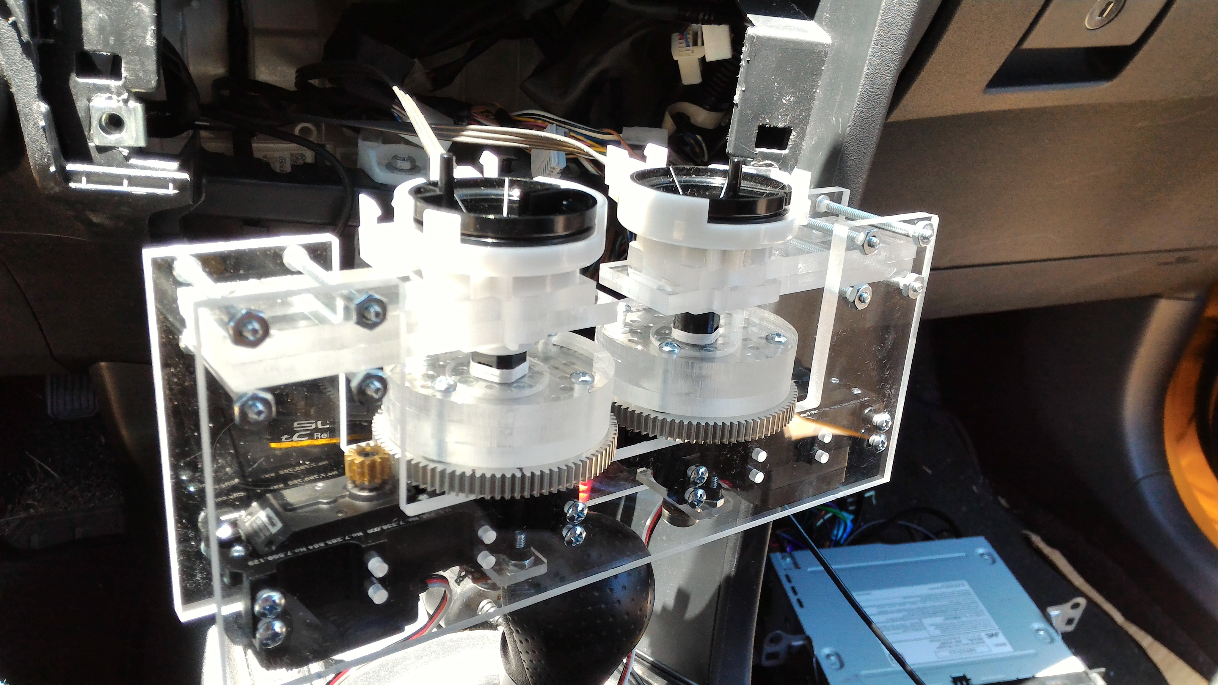
05/22/2016 at 19:22 • 0 commentsI've made some major progress on the mechanical part of controlling the heat and AC stuff. The knobs that control the temperature and which vents the air comes from are connected to cables that go into a box with (what I am assuming are) a bunch of butterfly valves. I have replaced the knobs with servos and now I can control the air box butterfly valves electronically.
![]()
On the left, I assembled everything and stuffed into the dash hole. This is pretty close to where it will be mounted when it comes time for it.
![]()
The one on the right shows the assembly before I stuffed it into the dash. The servos are mounted in "gearboxes" that give them 7:1 advantage. (https://www.sparkfun.com/products/12608) I think the servos could have turned the cable assembly without the gear reduction, but I didn't want to risk one of them burning out after the project is finished. The gear reduction makes it a little easier for the servo to achieve the desired position since I can program it so run at full power until it is very, very close to correct spot.
I used 1/4" acrylic for the brackets and (what I am calling) the adapter hubs.(The "adapter hubs" are screwed to the top of the big gear.) Why 1/4" acrylic? Because it's what was in my garage and my CNC router can cut it.
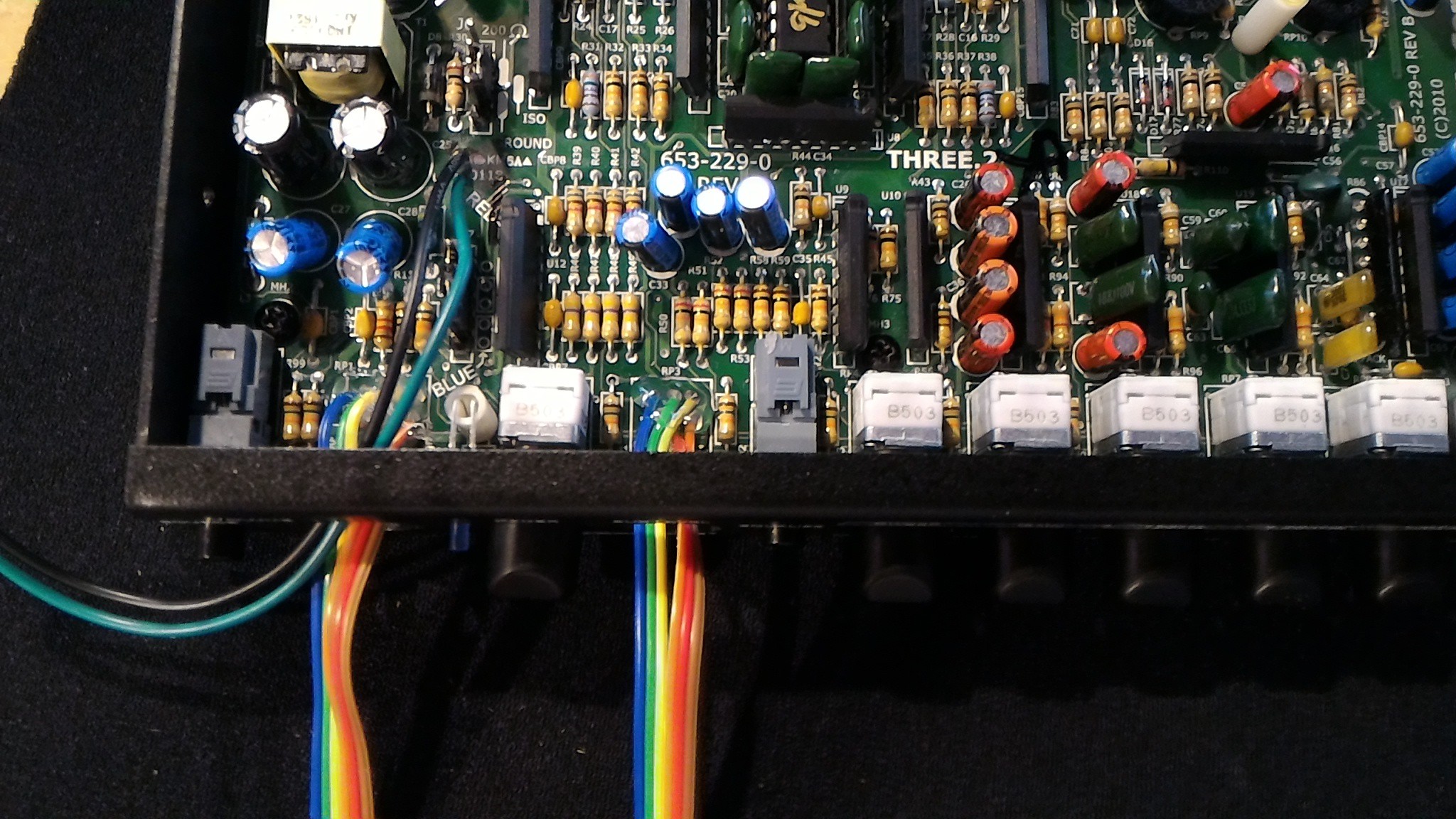
I've also made progress on some of the electronics. Right now I'm working on the EQ/Crossover/Line-driver that arrived a few days ago. It is an AudioControl Three.2, and it will take the output from the Schiit Modi and make it awesome. Actually, it is going to do exactly what it is meant to do. There is one thing about it that I have to modify though: volume knobs. This thing is going to be mounted inside the dash with no easy access but it will be my primary method of controlling the volume. To solve this problem, I am replacing the mechanical potentiometers with digital ones that are controlled via I2C (MCP45HV31).
Here you can see where I've desoldered the original pots and soldered in some ribbon cables. These will lead to a box with the digital pots, arduino, and CAN transceiver that will be mounted to the top of the EQ. The other two wires you see in the pic (black and green) are power for the digital pots. The MCP45HV31 is a "high voltage" part, meaning the potentiometer can be connected to a system with up to 36V between the high and low terminals of the pot. This EQ, being of such high quality, feeds a rather high voltage signal through the volume control pots: a max swing of -13V to +13V. The digital pot needs a power supply of at least the maximum swing voltage and luckily the EQ provides me with it. So, the black wire is connected to -14V and the green wire is connected to +14V. That's it for this update. Hopefully I'll have some functional stuff to demo in my next update.![]()
-
Software Progress
01/16/2016 at 21:09 • 0 commentsI have made some decent progress on the software side of things. The user interface is basically complete, but the back-end software on the R-Pi is nowhere near done. Here's a screenshot of the UI:
![]()
Here's a video demo:
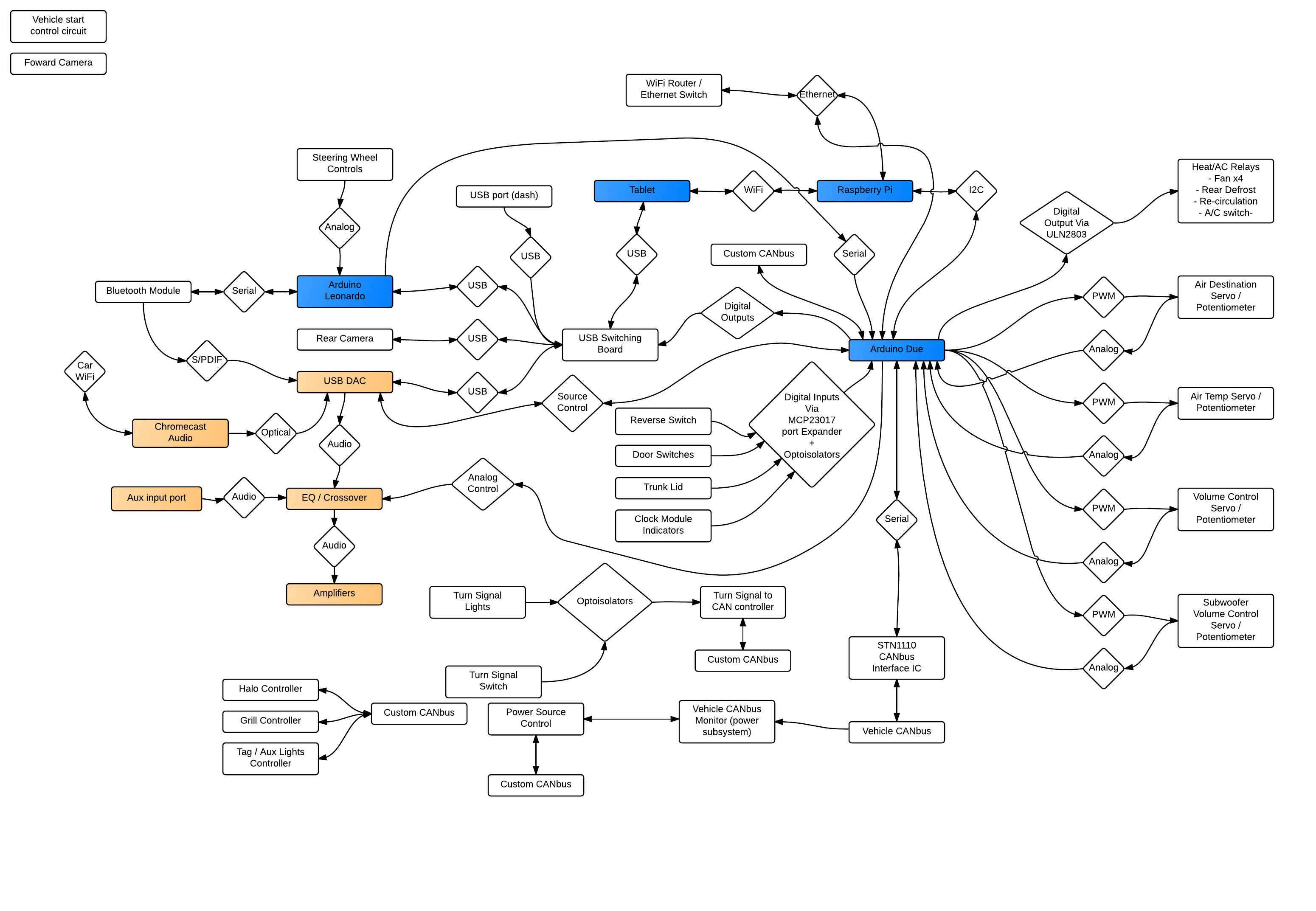
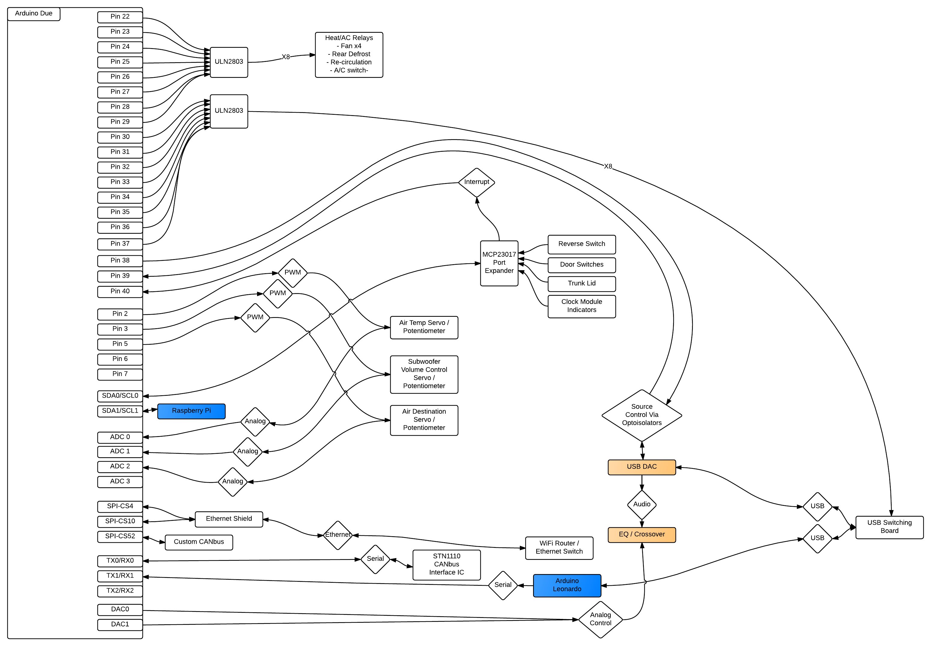
It's obviously an incomplete demo, but hey it's something. Also, most of the code I've been working on is available on Github.Just to give you an idea of what I have on my plate, here's a diagram of most of the components of this project...
And a sort of pseudo-schematic for the Arduino Due:![]()
I plan on updating the Google Docs file that has the full description of everything in it soon. I'm still working out some details and once that's done I'll get it updated. The link to the G-Docs file can be found on the main project page.![]()
That's all for now. I'm waiting for my brother to put the finishing touches on the dash piece so I can keep working on that part of this project. He works at an automotive body shop, so when it comes to fiberglass and bondo, he's got me covered. I'll post an update once he gets the piece back to me. Until then......
-
Just a quick update - Dash panel progression
12/14/2015 at 02:15 • 0 comments![]()
![]() The new dash panel is coming along nicely. The first picture shows an approximation of where the tablet will be mounted in the final piece. The second is a mock-up of the piece in the dash. That's all for now.
The new dash panel is coming along nicely. The first picture shows an approximation of where the tablet will be mounted in the final piece. The second is a mock-up of the piece in the dash. That's all for now. -
Actual Work Commencing
12/11/2015 at 01:14 • 0 commentsAfter much delay, I have finally started real work on this project once again. Here's a list of project accomplishments for the week:
1. Purchased a new tablet to install in the dash; a Samsung Galaxy Tab S2.
2. Completed some experiments with the new tablet and determined that I can go back to my original plan of doing away with the stereo head-unit of the car.
3. Started work on the new dash panel that will house the tablet.
Here's a pic of the progress on the dash panel:
![]()
As you can see in the pic, I've done away with the opening for the stereo and the opening where the clock, passenger airbag indicator light, and hazard light switch used to be. The new piece still needs to be cleaned up and the edges trimmed down but it is a start.
As for the tablet and related experiments, I have solved the one big issue I had when I started this project: audio. I want to use the tablet as the audio source for music but retain the ability to connect my cell phone through Bluetooth for phone calls. Through several iterations of methods of connecting the tablet's audio and the BT call audio to the car, and many revisions of the overall vision of this project, I came to the conclusion that I couldn't have all the features I wanted. Enter the new tablet.
As it turns out, the Tab S2 has the ability to output audio through USB audio devices. It also supports USB hubs, cameras, keyboards (with media keys), and pretty much anything that you can find an app to use it with. It also does this nifty thing where when you turn on the WiFi Hotspot, it creates a proper IP routing table. This may not seem important on the surface, but it allows the tablet to communicate with the RasPi without interrupting its own ability to access the internet. It also has the obvious advantage that it gives the RasPi and internet connection.
Back to USB. Audio output will be handled by a USB DAC, probably a Schiit Audio Modi 2 Uber. Track controls will be implemented through a virtual keyboard through an Arduino Leonardo. The backup camera will be a Logitech HD Pro C270 (or C920, perhaps) webcam being displayed through an app called CameraFi. The last port on my USB hub will be connected to the stock USB plug in the dash.
There is still one issue with the tablet: charging. I don't want to have to bring the tablet inside every day to charge it but it won't charge will USB devices are attached. Hopefully I can hack a cable to get it to charge while the USB devices are connected, but if not, I'll have to use relays to simulate the disconnection of the USB stuff. That would mean setting up an auxiliary battery that is charged when the engine is running and charges the tablet when the engine is off. Perhaps those details will come in my next project log.
When it comes to audio, here's how I'm gonna set it up: tablet --USB-- > DAC --> line level preamp --> level control --> power amps. The DAC also has a S/PDIF input which will be the insertion point for the call audio from the BT module. It will be controlled directly by the RasPi which will receive an interrupt when a call arrives and display the call on the tablet screen. The RasPi will control the level of the signal going to the power amps through some means that I haven't fully worked out. I want to be able to do this so that a set volume can recalled whenever a telephone call comes in.
More work will done in the coming weeks and if I remember, I'll post more updates.
-
Power Supply Build (part 1)
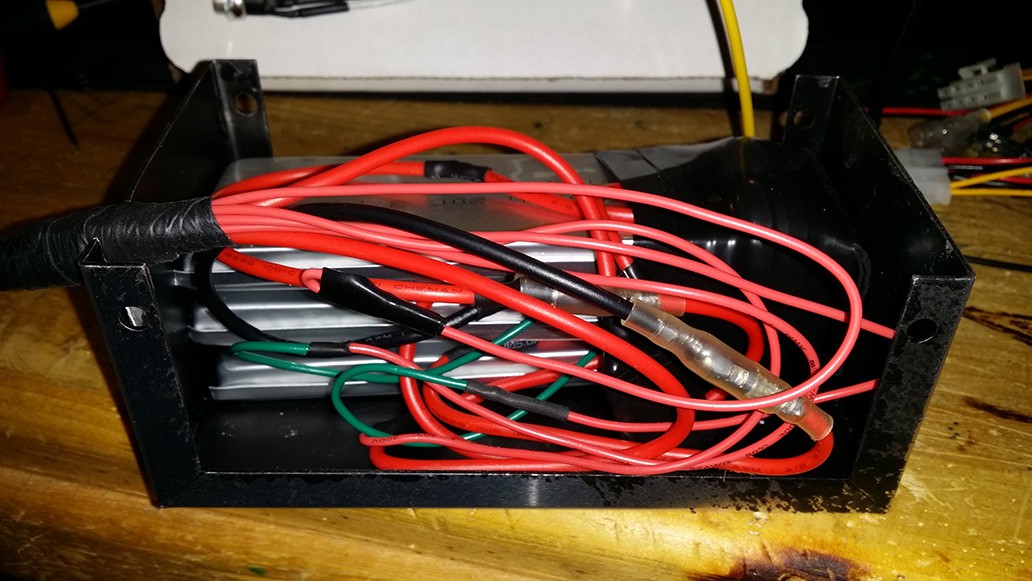
02/28/2015 at 13:33 • 0 commentsI've made a fair amount of progress on the power supply for the various 5 volt and 3.3 volt components (Arduinos, tablet, etc.). This includes the battery for powering the remote start controller and the standby controller for lights.
{ Battery pack showing the mess of wire I created along with the three single cell batteries }![]()
{ The completed battery pack }![]()
The battery pack is made of three Turnigy 5000mAh 1S 20C 3.7V Lipoly batteries connected in series to form a 5Ah 3S 11.1V pack. The battery pack is directly connected to a Mini-Box OpenUPS. The OpenUPS charges the battery pack and manages battery run time after the ignition has been switched off. Once the ignition is switched off, the battery powers certain devices for a preset amount of time before removing power from them (e.g. RasPi). The controllers that require battery power all the time will be connected directly to the battery pack through efficient DC-DC buck converters. I plan on building within the power supply a controller that monitors battery voltage, and in the event the battery voltage dips below safe voltage on any cell, it will completely disconnect the battery pack through latching relays. The OpenUPS feeds into a Mini-Box PicoPSU that outputs 12V, 5V, and 3.3V. This supplies all devices that require 3.3 volts and any device that requires a shutdown timer on 12 volts or 5 volts.
For devices that do not require a shutdown timer but are not high power devices, 5V and 12V will be provided using a pair of Mini-Box DC-DC USB 200 power supplies. This provides plenty of power for all the microcontrollers and the handful of 12V devices that require regulated voltage (camera, DVR). More photos and details to come.
-
Been a while since updating, still working on it
02/18/2015 at 16:58 • 0 commentsSo, it has been quite a while since the last time I updated this project, but I an still working on it and have made some progress. Once again I have revised the vision I have for the dash and I'm going back to the plan installing of the tablet in the dash. I've also made some progress on the power regulation and delivery system and have come up with a new idea for communication between modules. I'll be posting details and photos soon.
-
Entering TheHackadayPrize, Installing the new head unit
07/12/2014 at 06:09 • 0 commentsAfter much debating with myself, I've decided to enter this project into TheHackadayPrize contest. One of the requirements for a project to be eligible is that the hack be connected somehow. Going back and reading my project description I realized that I left out the bit about remote starting the vehicle from any internet connected device and potentially being able to stream video from the car's camera and reading log data.The data connection in the Android device will help make this possible. I'll be posting more details as soon as I've had a chance to make some headway on that front.
![]()
In the meantime, how about some details about how I managed to make the new head unit (JVC JW-V50BT) work with the existing USB, auxiliary input, and microphone in my car? Starting with the easy stuff. The USB and auxiliary connections were fairly easy. It was just a matter of examining the wiring schematic for the car and making adapter cables. The microphone was a different story.
The new head unit came with a crappy little mic that they expect to be mounted on the dash with two-sided tape. But I figured that would be silly since my car came stock with a mic built into the dome-light assembly. Upon comparing the connections of the two mics, it was clearly apparent that this would definitely be more of a hack than an adaptation. To the right is the stock connector for the mic. The new mic had a 1/8 inch TS connector on it. The goal: hack a 2 conductor connection to work with a 5 conductor connection (actually 4, but there's 5 wires there).
![]()
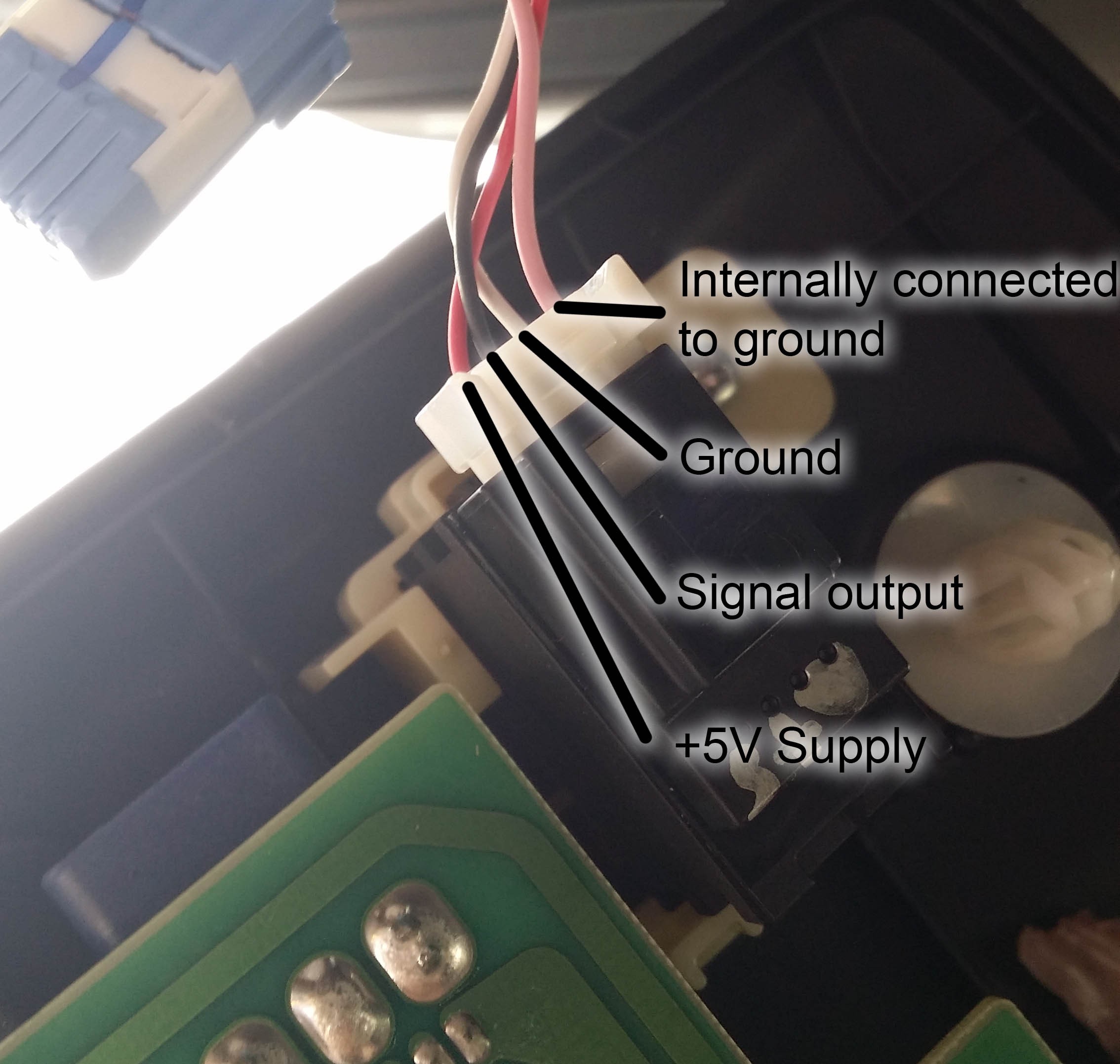
This is the connection to the microphone module. I took it apart (and forgot to take pictures) and figured out which wire served which function. I had done a bit of searching on the web to see if I could find anyone that had already sniffed out the functions of each of these wires and the best information I could find was that the microphone requires power. The schematic lists the connections to the mic module as SNS2 (pink), MCO+ (black), MCO- (white), and MACC (red). (The schematic also shows the shielding around the cable. That would be the gray wire.) Although I wasn't certain, I figured that they were, respectively, sense (for the stock head unit to detect the presence of the mic, Bluetooth in that head unit will not work without it), signal output positive, signal output negative, and accessory power.
This turned out to be pretty easy to confirm once I had a look at the PCB. The white and pink wires are both connected to the ground plane on the PCB inside the module. The 5 volt supply has an AC blocking capacitor near the connector. The positive side of the signal has a DC blocking capacitor near the connector. Knowing this information made it possible for me to work out a way to connect it to the new head unit.
Finding a 5 volt supply for the microphone wasn't too difficult since I've got a couple of spare USB cell phone chargers laying around. That was just a matter of splicing them together. The signal wire was a different story. First step was to figure out which side of the 1/8"TS connector was connected to ground. A simple multimeter/resistor combination made this trivially easy. Then on to connecting the two. Since the stock mic module has a built in pre-amp, I figured it would output a really hot signal. I hooked up my handy little DSO Nano o-scope to output of the stock mic and saw a nice waveform in sync with door chime. I noted that the peak voltage was about 100mV.
Then I hooked it up to the crappy mic that came with head unit and couldn't get any decent reading out of it. I tried talking directly into the mic, tapping it, holding it up to the speaker on my cell phone. It never registered any voltage. And this was with it connected to the head unit. What's more is that the head unit acted like the mic wasn't even plugged in. This was unsettling and very annoying.
So what is a good hacker to do? Well, pop open the brand new $400 head unit and poke around of course. Alas, in my poking around I found that the mic connects (almost) directly to the Bluetooth module inside the unit. The PCB with the 1/8" plug soldered to it had a short pair of wires (with JST connectors on either end) connecting it to the PCB with the Bluetooth module soldered to it. After tracing traces and I concluded that this pair of wires must carry the mic signal and I should hook directly to that. Knowing that most Bluetooth modules can't handle a hot signal on the mic input, I grabbed my soldering iron, a 1 meg-ohm resistor, a whole bag of 10k's and went to work.
Firstly, I had break to out the connection to the Bluetooth mic input so that I can get at it from outside the unit's case. A couple of sacrificial male jumper wires did the trick. Next, figure out how much attenuation the signal needed. I made a simple voltage divider using the 1M and a single 10k for my first try, and worked my way up to a 1M and 110k combination. This yielded the best sound quality and volume. Solder, heat-shrink, and done.
Overall, I am quite pleased with how the install went. The USB and AUX inputs work as expected. The head unit works great with the Galaxy S3, and as a bonus, it also works a a great monitor for any other HDMI source that can output 480P60, namely a GoPro. I think I might install my old GoPro so that it looks out the windshield and keeps a running video log (useful in the event of an accident).
RasPi Car Computer
Raspberry Pi car computer with Bluetooth connectivity, OBD-II integration, Arduino, and (obligatory) RGB LEDs.


 The new dash panel is coming along nicely. The first picture shows an approximation of where the tablet will be mounted in the final piece. The second is a mock-up of the piece in the dash. That's all for now.