-
Designing the Line PCBs
06/30/2016 at 16:42 • 0 comments![]()
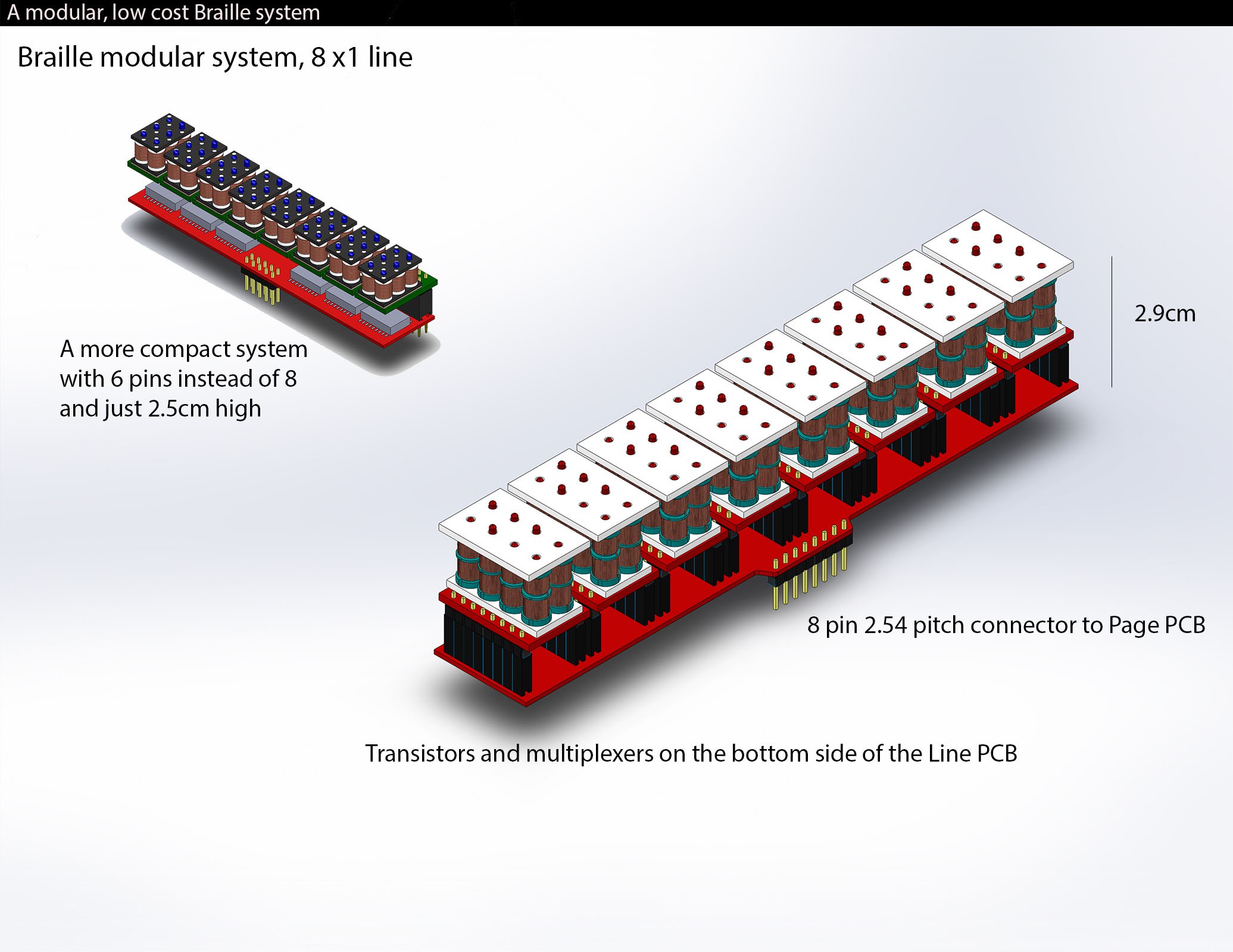
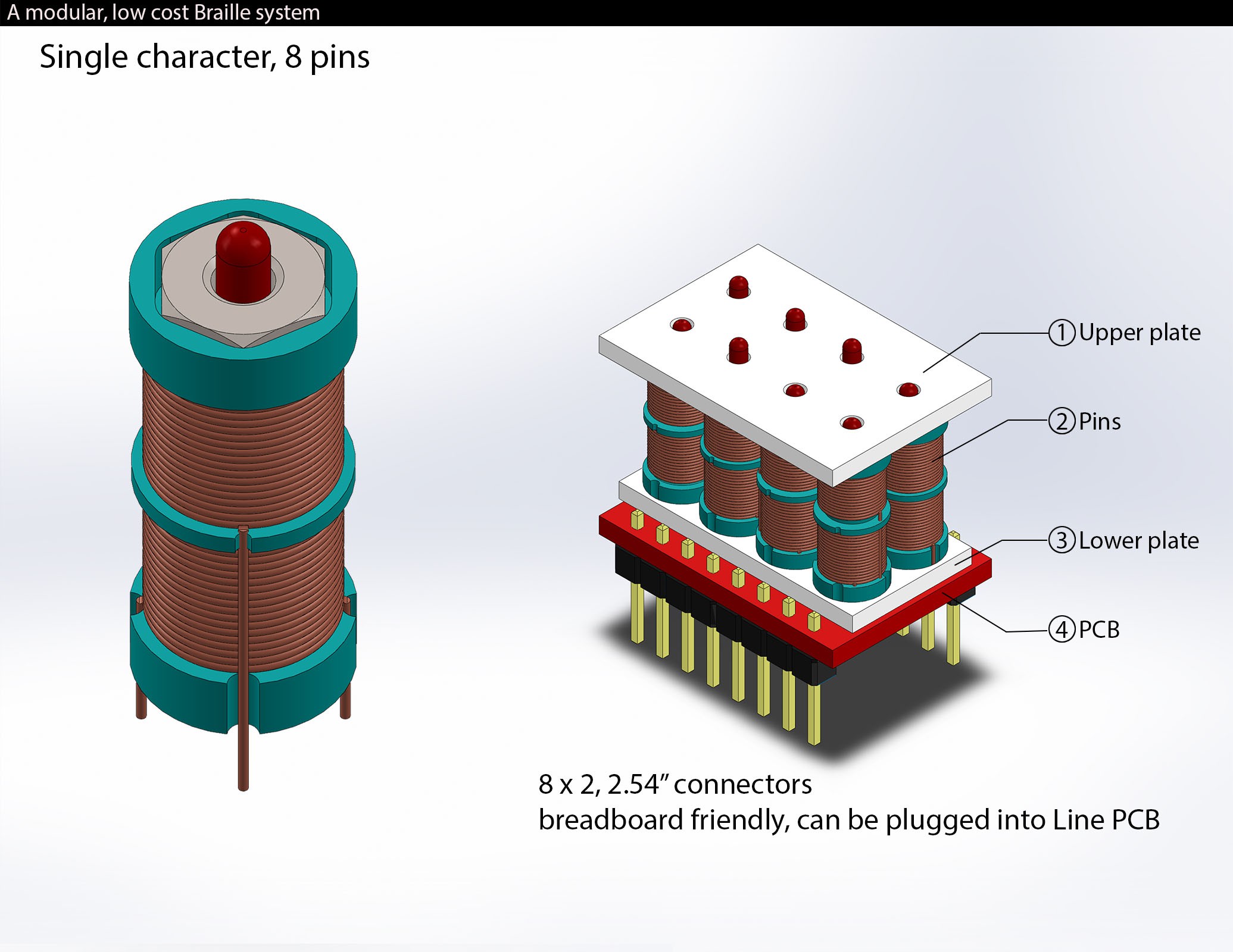
I am now designing the Line PCB, where you can stack 8 /10 characters, with integrated multiplexed control.
-
Building the first working character, and some considerations
06/28/2016 at 11:53 • 0 comments![]()
Now that the Pin system is working, I will continue by designing and assembling an entire character.
Size optimization has still big space for improvements, and tests with just one or two small magnets instead of three will be made.
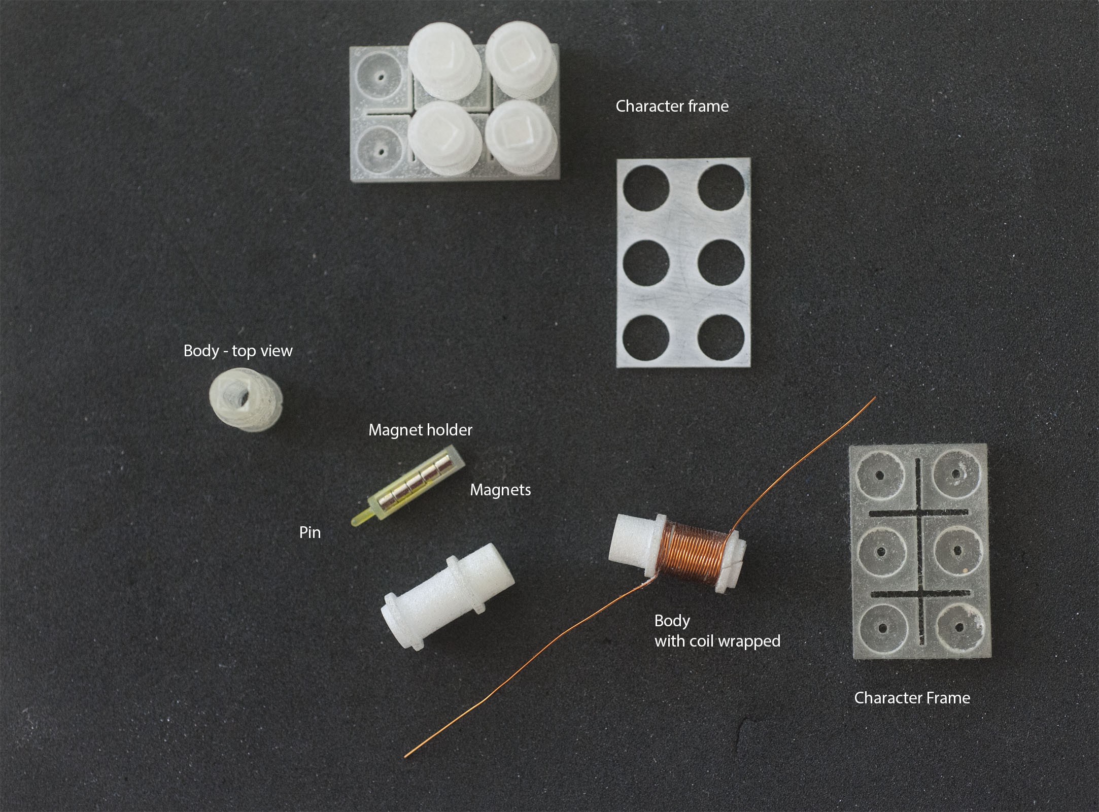
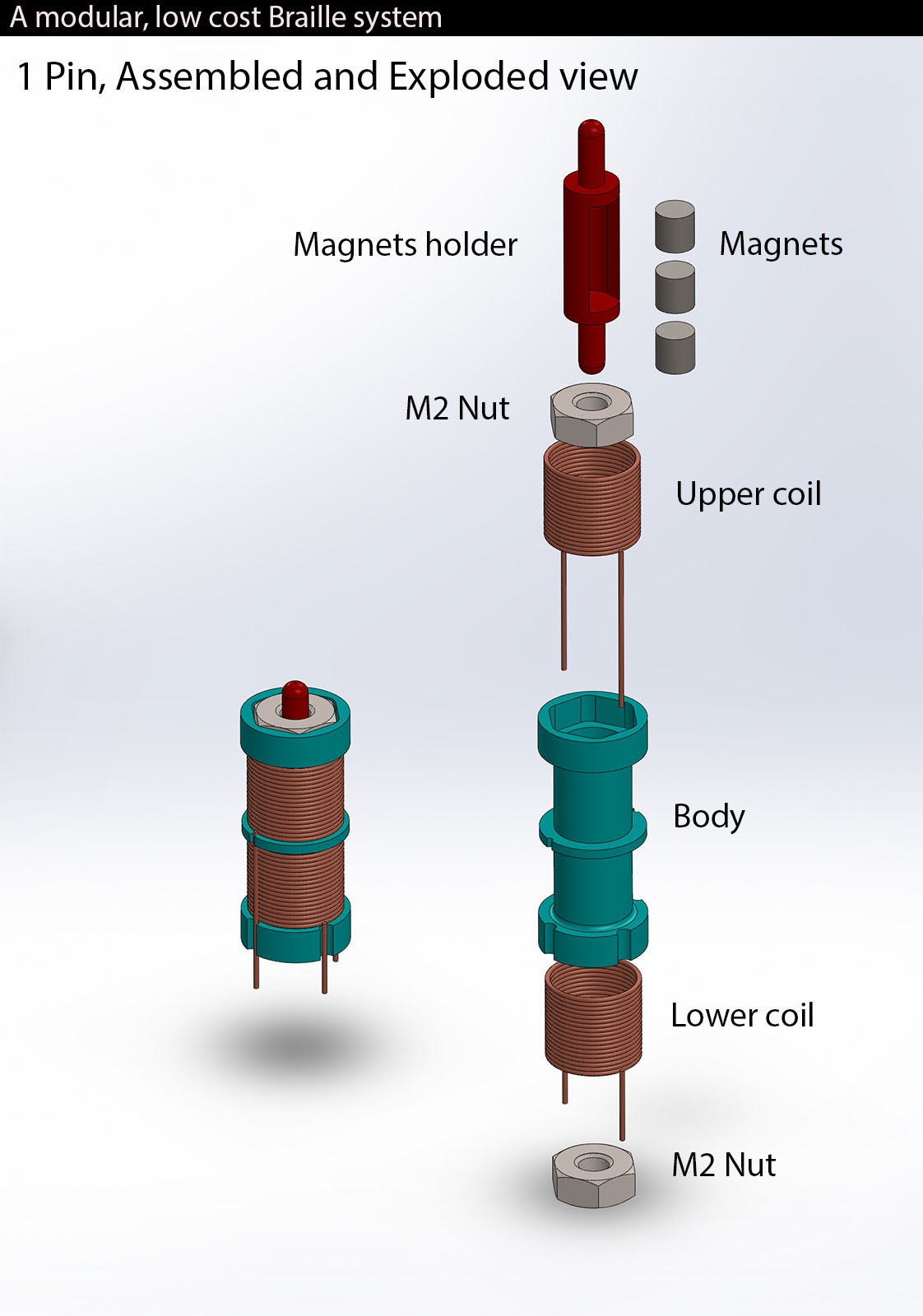
The biggest goal I have reached at the moment is that each pin is simple, is made up of just 2 printed parts (that can be made with injection molding for mass production), 2x M2 nuts, some enameled wire, and commercially available magnets. Total cost (for the prototype, not for a scaled production) for each Pin was less than 0.6€ for the magnets, 0.5€ for nuts, copper wire and UV resin for DLP for the 3d printed parts. I think it is one of the lowest price ever reached for a working Braille system.
The electronics will be integrated in the "Line PCB", and at the moment, the system is designed to be Maker friendly, breadboard compatible.
-
Testing the current version
06/28/2016 at 11:31 • 0 commentsI 3D printed the body and magnet holder, assembled the Pin, and tested with a button-activated simple Arduino sketch and related electronics.
![]()
-
The current (working) version
06/28/2016 at 11:26 • 0 comments![]()
This exploded view shows how a Pin is designed. Each character has 6/8 of them.
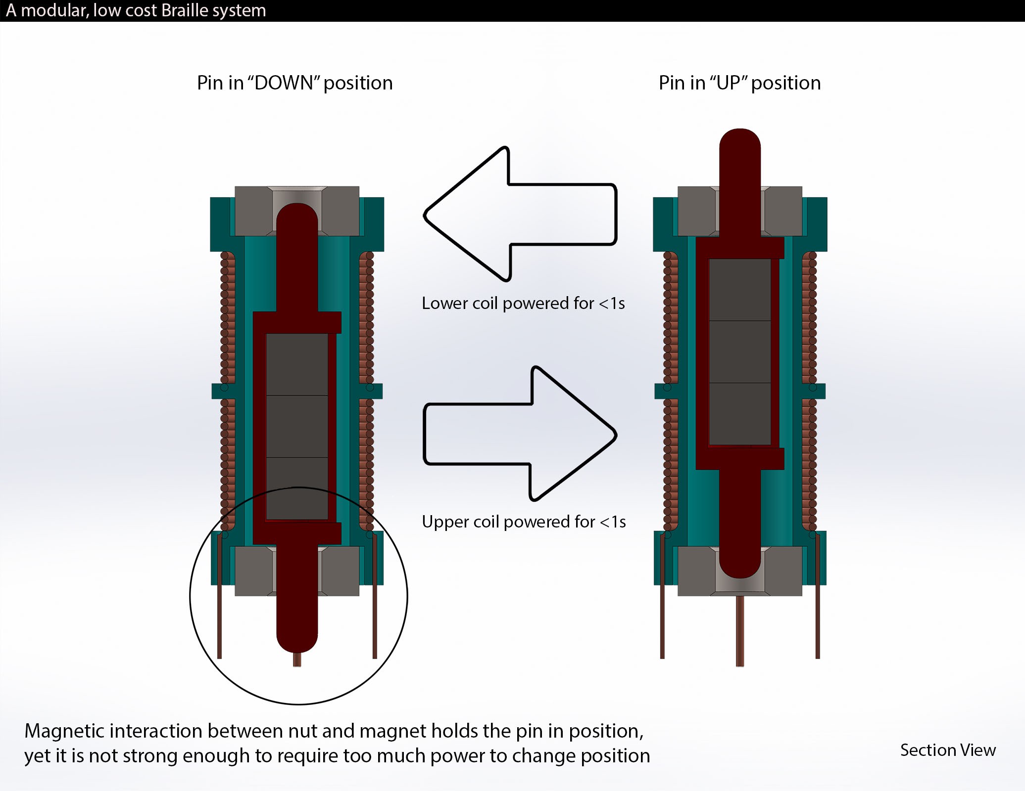
![]() And the following video shows how it woks:
And the following video shows how it woks: -
A more exotic iteration
06/28/2016 at 11:21 • 0 commentsAt some point during the quest for an affordable, simple bi-stable way to design the pin for the Braille system, I came up with this, It worked, and by transmitting the movement into the linear motion of the pin, I could have designed an entire 6 pins character.
In the end I did not use this system, as it was quite complex to be assembled, and to as cheap as my main idea.
![]() The idea was to use to small (15mm long) 1mm thick Nitinol wires. They have been annealed into a straight shape; a nichrome wire was wrapped around each one, so when it was powered, the heating was causing the nitinol wire to become straight again, while the other one was flexing. A string connected them, and a small magnet at each end would have kept the end in place for both positions.
The idea was to use to small (15mm long) 1mm thick Nitinol wires. They have been annealed into a straight shape; a nichrome wire was wrapped around each one, so when it was powered, the heating was causing the nitinol wire to become straight again, while the other one was flexing. A string connected them, and a small magnet at each end would have kept the end in place for both positions. -
The new 3d printed version
06/28/2016 at 10:53 • 0 comments![]()
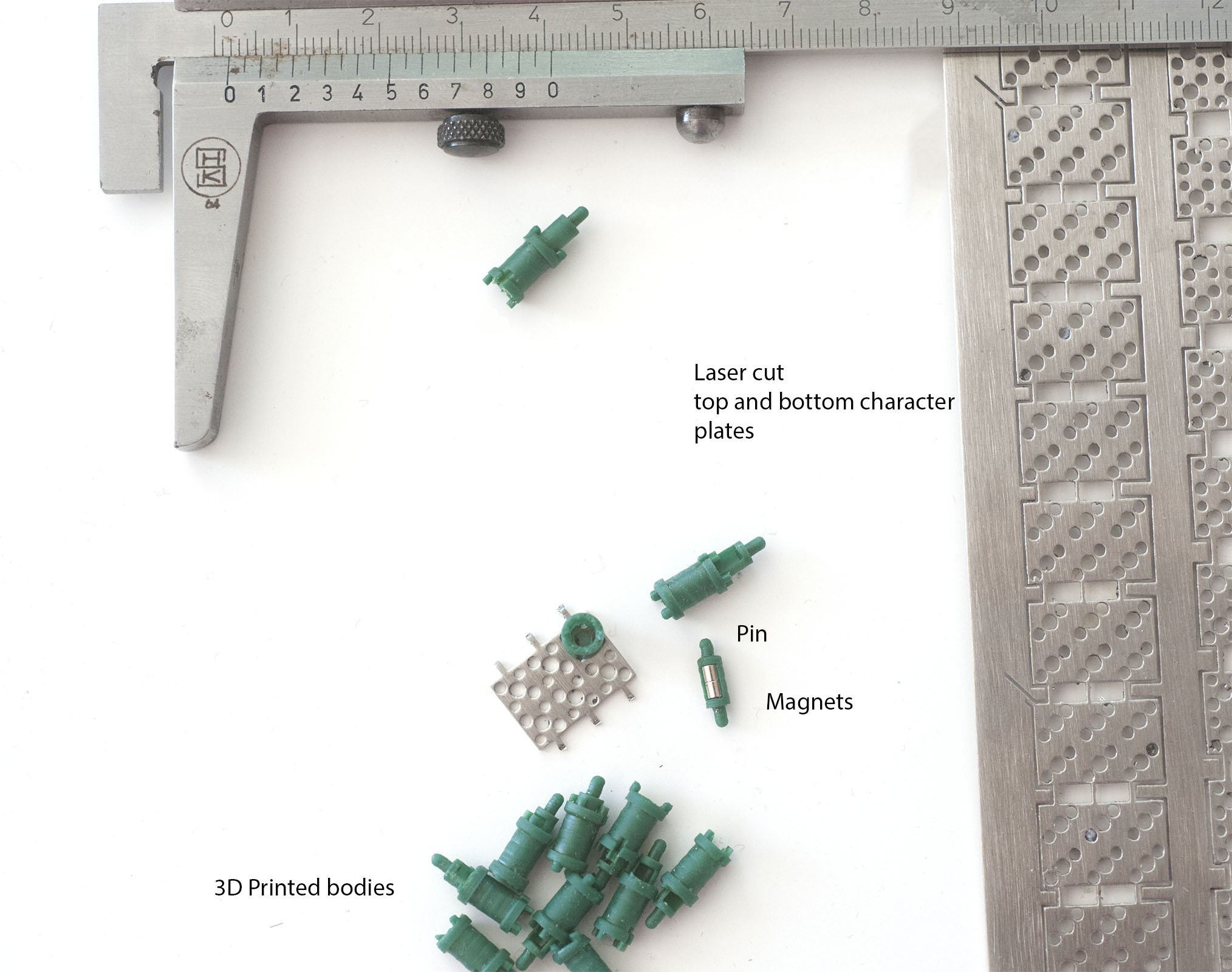
In this newer version i 3D printed the parts with the DLP 3D printer I designed. The steel plates were lasercut, and my idea was to use one plate for the whole character instead of one for each pin; unfortunately, i later found out that the steel they used was problably stainless steel, and almost not ferromagnetic (also quite expensive to make).
-
The first 3D Printed prototype
06/28/2016 at 10:41 • 0 commentsThe first 3d printed prototype, shows the parts the structure of a character; I had these parts made from a service, and they were quite expensive at that time since I needed some precision, and quite small parts. The metal plates are not shown in this picture, they should have been some small (3x3mm) squares cut of 1mm steel plate, with a hole in the middle, quite difficult to get.
![]()
-
The first prototype
06/28/2016 at 10:32 • 0 comments![]()
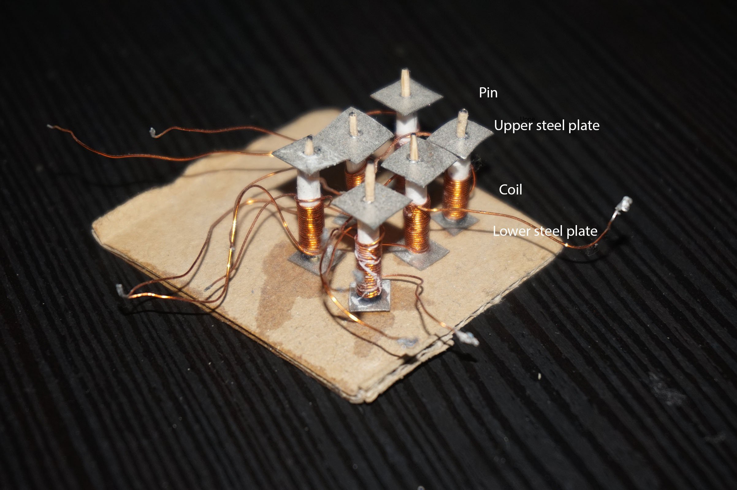
The first prototype used some very small cylindrical magnets, with wood pins glued at each end.
They were put inside a paper cylinder with a coil wrapped around.
Steel plates with a hole in the middle were glued at each end. Powering the coil moved the pin up or down, and the steel plate were keeping the pin in position, so it can be "read" without pushing the pin down.
MOLBED Modular Low cost Braille Electronic Display
A project that I started in 2014, aimed to develop a low cost and modular refreshable Braille system
 Madaeon

 And the following video shows how it woks:
 The idea was to use to small (15mm long) 1mm thick Nitinol wires. They have been annealed into a straight shape; a nichrome wire was wrapped around each one, so when it was powered, the heating was causing the nitinol wire to become straight again, while the other one was flexing. A string connected them, and a small magnet at each end would have kept the end in place for both positions.