-
1Step 1
The design of the robot is open-sourced by evivetoolkit under creative commons-Share alike-Non commercial-license.
You can download the CAD model from our GrabCAD profile.
![]()
-
2Step 2
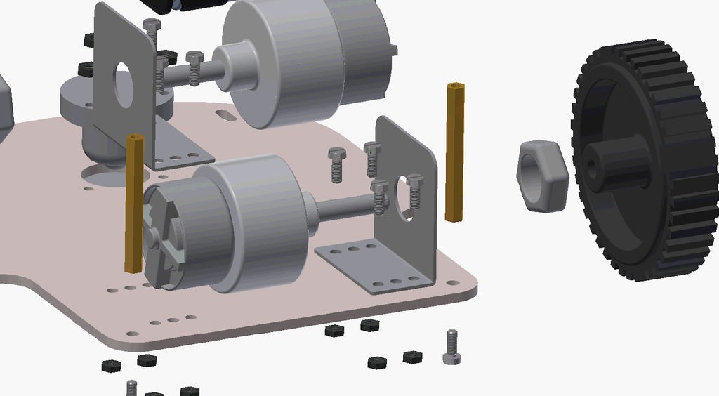
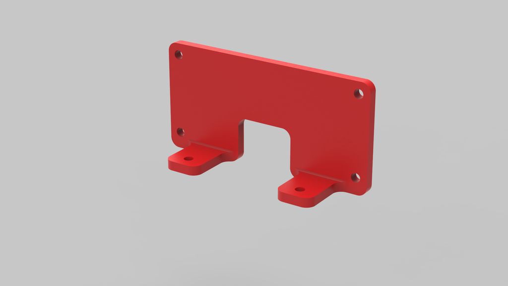
First, we will mount motor clamps which is used to fix motors to the base plate. The plate have the mounts for two clamps. Mount the clamp with for nut bolts tightly.
![]()
-
3Step 3
Mounting motors and wheels to base plate
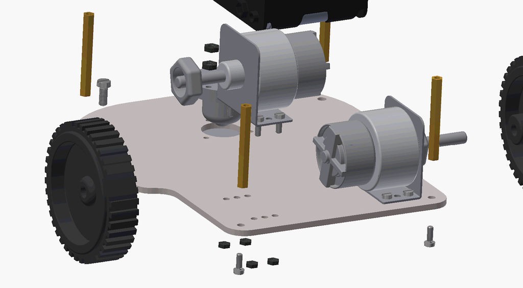
After you have mounted the clamps, then we will mount motors. Unscrew the nut from the motor, then insert the motor in the clamp and screw back the nut to fix the motor in the clamp.
![]()
Then do the same thing for the second motor motor.
![]()
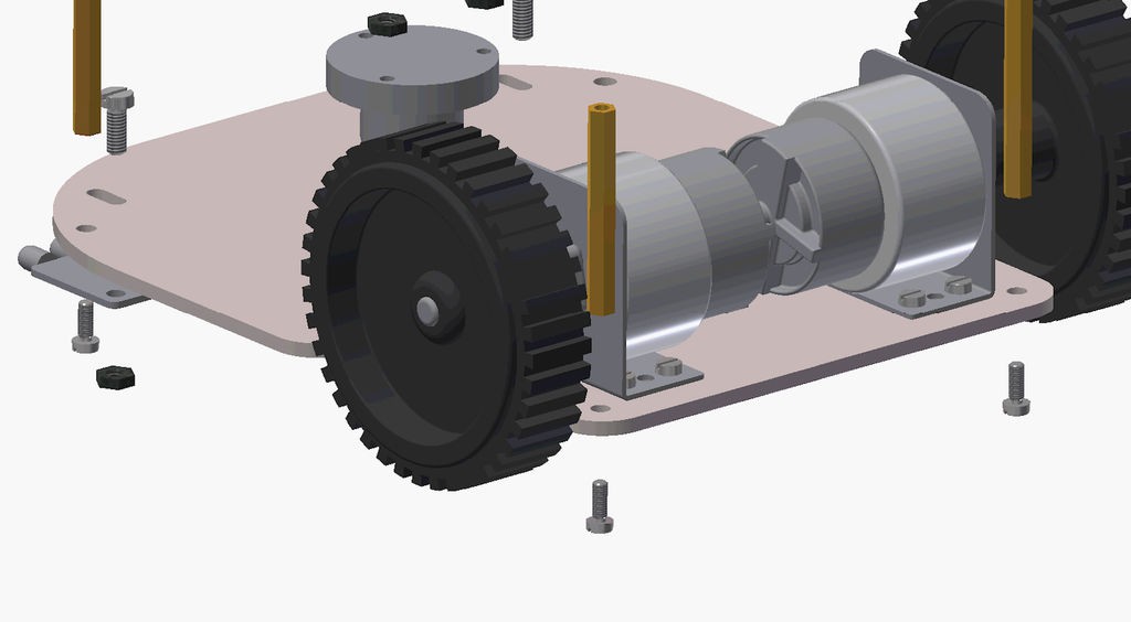
After this, you can mount the two wheels on the motor's shaft. Make sure that the wheels are compatible with the motor so that it can be attached and screwed easily and firmly.
![]()
-
4Step 4
Mounting the Castor
Now we will mount a castor in the hole at the center of the base plate. Take care to place it in such a way that the rolling ball is at the bottom, and there is very less ground clearance. Castor helps in a great way in controlling the robot with two wheels. If you use a four wheel drive robot, then you will find the robot less efficient and hard to level all the four wheels. So using castor can act as a smart way.
![]()
-
5Step 5
Placing the battery
Secure the battery in the area provided between castor and motors, using double sided tape or screws to power the motors through evive.
As we have used 12- Volt battery, so we don't need to worry as for the 12 volt dc motor it is recommended to not increase the voltage above 12 volt. So, if you are using a battery having voltage more than 12 volt than make sure that you are getting a 12 volt output from VVR pins using the side potentiometer of evive.
![]()
-
6Step 6
Mounting standoffs for the upper plate
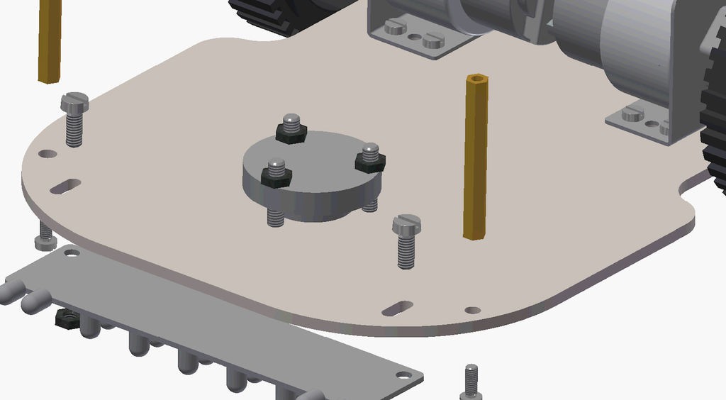
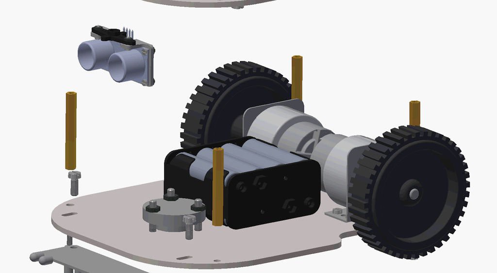
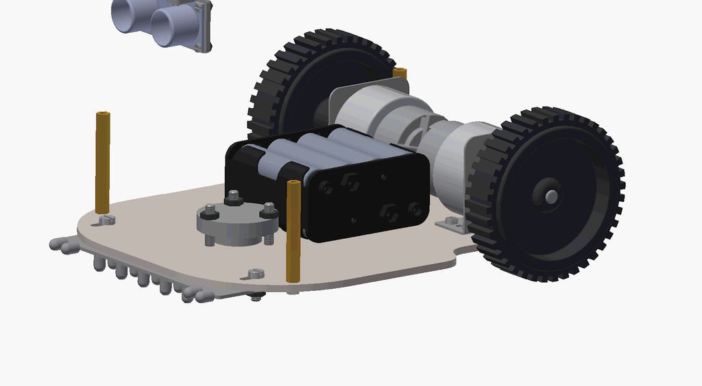
We will need to have a connection between the upper and the base plate. For this we will mount four standoffs on the holes provided on the base Plate. You can get these standoffs from any hardware shop. It has closing screws at two ends which is used from the other side of the plate, you can understand this from the video easily.
![]()
-
7Step 7
Mounting the evive on the upper plate
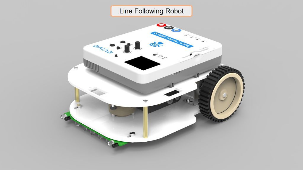
Now, We have to mount evive on the upper plate. evive is mounted using bolts on the upper plate which you can see in the image.
-
8Step 8
Making the sensor holder for the servo
To avoid any hassle in mounting the ultrasonic sensor on top of micro servo motor, we have 3D printed the part. The STEP file can be downloaded from here (GrabCAD).
![]()
-
9Step 9
STEP 1: Adding the line following sensor
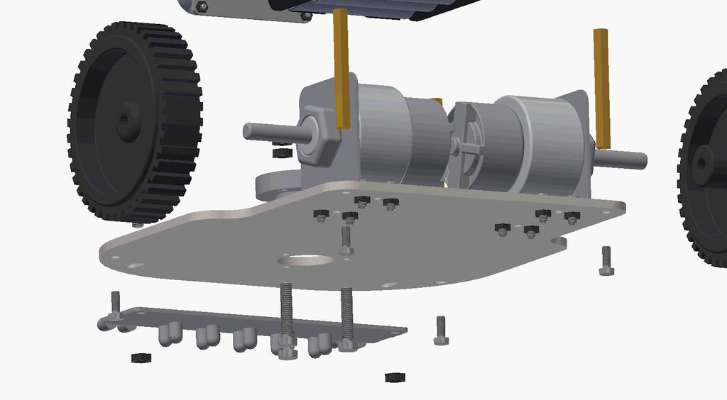
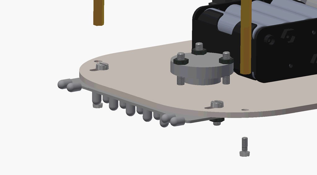
Now mount the line following sensor such that the IR LEDs face downwards. Adjust the distance from the ground. It should be between 2-10 mm. (If your line following sensor has variacs, it is required to adjust them for setting the cutoff value for say white and black).
It is recommended to you that put the sensor below the chassis and attach it with screws as shown in figure.
![]()
![]()
-
10Step 10
STEP 2: Adding the ultrasonic sensor and servo
Now one can mount servo and ultrasonic sensor on the upper plate to make the collision avoiding robot. This will enable the sensor to detect obstacle and scan distance in the 2-D plane.
Firstly, insert the servo in the slot given and fix it using the screws. Now, add the ultrasonic sensor in the servo, but to put the ultrasonic sensor in the servo you need a base, we have printed it using a 3-D printer.
Also with more sensors like compass, IMU and wheel encoders you can make partially autonomous mobile robot like this.
Making a Modular Differential Drive Robot
assembling modular mobile robot for making different type of robots like line following, obstacle avoidance etc.
 evive toolkit
Discussions
Become a Hackaday.io Member
Create an account to leave a comment. Already have an account? Log In.