-
1Step 1
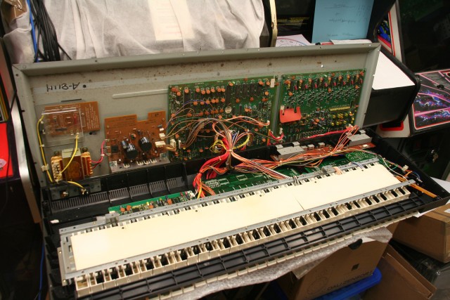
Unplug the synth.
Turn it face-down (propping it up so you don't damage the joystick), remove all the screws around the perimeter, and the five large screws in the centre section.
Carefully lift open the synth. It should look like this.
If, as with mine, there is a biro rattling around inside, now is a good time to remove it. :-)
![]()
-
2Step 2
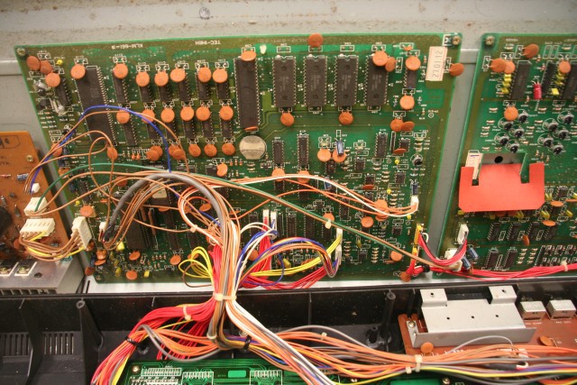
We need to remove the middle PCB. This one.
![]()
-
3Step 3
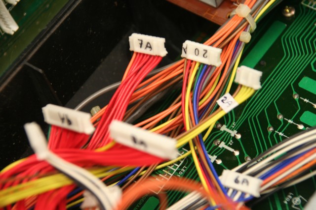
Carefully unplug all of the connectors from the board, EXCEPT for CN12A and CN13A which are soldered to the board - these need to be unplugged from the other end.
Label the connectors so you know where they go afterwards. For the larger ones I wrote the connector number on the side with permanent marker, for the smaller ones I attached a label to the wire.
![]()
-
4Step 4
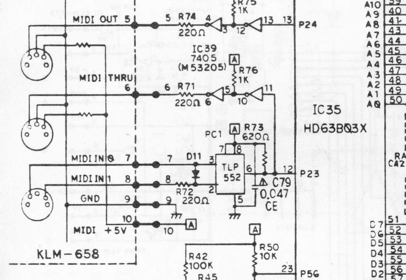
One of the nice things about working with old kit, is that the manuals actually give you tons of technical information. In this case, the Service Manual has a detailed schematic. The relevant bit is on page 18:
![]()
So, MIDI IN goes through an Opto-Isolator TLP552 (as per the MIDI standard, to prevent ground loops), then gets sent:
a. through a couple of inverters to MIDI THRU outpit, and
b. to pin 12 (NOT 23 - carefull with that diagram!) of the CPU.
Since we don't want to affect MIDI THRU, but we do want to affect the MIDI stream before it reaches the CPU, then be need to do our hack somewhere between pin 12 of the CPU, and the first solder connection.
-
5Step 5
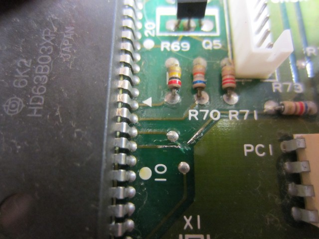
Here is a close-up of the circuit board, after I cut the track to pin 12. (Note that 10 is helpfully labelled on the silk screen!)
![]()
-
6Step 6
The next step was to scrape off some solder resist, and solder up 4 pins worth of 0.1" header:
Black goes to ground (connection not clearly visible here, but it is the large copper area).
Red goes to +5V, which can be conveniently picked up on the side of R73 furthest from the CPU. ('A' on the schematic is +5V).
Yellow goes directly to pin 12 of the CPU. This will go to the Tx pin on the arduino.
Pink goes to the side of R73 nearest to the CPU.
(In retrospect, I should have used thinner wire, for less danger of lifting anything).
If a jumper is placed across the yellow and pink pins, then the synth should work as before. This is a good thing to test. Of course, DO NOT bridge the power pins by mistake, or you might not have a synth any more.
![]()
-
7Step 7
Here it is with a bit of heatshrink added to prevent any embarrassing short circuits.
![]()
-
8Step 8
Interlude:
At this point I decided it was a good time to replace the battery, before it leaked or died. This wipes the patches from memory, so if you want them then make sure you have saved them and know how to restore them using SYSEX or tape.
The original battery was soldered in place. Not awesome. I removed it with a combination of cutters, soldering iron and solder sucker.
You then need to install a CR2032 coin cell holder. I'm not aware of any that fit the footprint, so I ended up having to drill a new hole in the PCB. Luckily, there is plenty of board area free of tracks in this area, so it wasn't hard to find a suitable place.
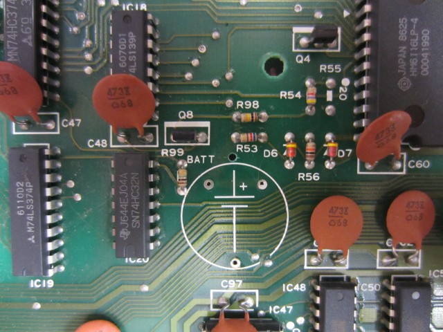
There it is, just below R53:
![]()
-
9Step 9
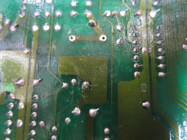
And the other side, after soldering the cell holder. Note that the new hole happily lines up with the +ve track, so no need for a bodge wire.
SUPER IMPORTANT: Check at least five times that you have the polarity correct before you solder in the battery holder, otherwise very bad things will happen.
![]()
Insert a new 3V cell into the holder, and the interlude is finished.
-
10Step 10
Reinstall the PCB, and reconnect all the connectors.
The synth is now ready, time to prepare the Nano.
It needs four connections to connect to our 4-way header in the synth. I used some 'Dupont' cables cut in half, and taped together to form the 4-way socket. The other ends connect to the +5V (red), GND (black), Tx (yellow) and Rx (pink) pins like this: (Notice the non-standard CH340G USB to Serial chip on this clone)![]() and this:
and this:![]()
Korg DW-8000 MIDI Enhancer
To get the Korg DW-8000 synth to understand MIDI CC messages for parameter control.


 and this:
Discussions
Become a Hackaday.io Member
Create an account to leave a comment. Already have an account? Log In.
Great project!
I immediately had the idea to implement something similar for the korg DSS-1 (according to the DSS-1 circuit diagram based on HD63B03X - installing arduino nano should not be difficult and it’s easy to implement)! All that remains is to check the MIDI implementation chart between DW8000 and DSS-1.
the DSS-1 circuit diagram here: http://www.buchty.net/korg/files/Korg%20DSS-1%20Service%20Manual.pdf
a part of MIDI-in: https://drive.google.com/file/d/17oAGBd8XjE5fB0oQps4Yi4UmF9N4dLsj/view?usp=sharing
I installed the Arduino Nano on the EX-8000 and DSS-1 - and it turned out to be easier than it seemed during the tutorial!
https://drive.google.com/file/d/1UEsWROlFnUDzey74AkZHRd9Xd09-UQSA/view?usp=sharing
Here is the installation process on the Korg DSS-1:
Arduino is easier to install on the KLM-788 Jack panel. In this case, power is supplied to the CN26B connector (pins #5 and #6), and you can break the cord pin #2 for RX and TX connections with a MIDI patch cable going to the main board of the KLM-781 CPU-II - HD63B03X.
https://drive.google.com/file/d/14mo3EcSkTfE6uKRucdmmyQD4zfVidJgB/view?usp=sharing
https://drive.google.com/file/d/1HFgKfoweHuOlv_Y2G56s5leQDn0_Krco/view?usp=sharing
https://drive.google.com/file/d/1Of3SW8RS_1S5IX40r0XSb6N5JaTI9g5I/view?usp=sharing
the value what I needed to recoding was to change the device ID to DSS-1 - 0x0b, in 34 lines of code
аnd I using the control sirface - SSL nucleus2 in 2 CC#-mode - good job!
Are you sure? yes | no
After several unsuccessful tries I finally got the project working on my DW-8000! It seems that at least with the current MIDI arduino library there is a discrepancy between the MIDI channel numbering as received from the MIDI lib which runs from 1 to 16 and the MIDI channel numbering inside the SysEx Messages which run from 0 to 15. I removed the code parts where there was a check if the declared dwChannel was identical to the incoming message channel, and hardcoded it to only work on channel 1.
Are you sure? yes | no
I just bought an EX-8000. Purchased an Arduino Nano today to try this mod. I'll post results. I have my Korg NanoKontrol2 connected to my PC running Cakewalk. The EX-800 is connected via midi to PC and works with Cakewalk. So shouldn't this combination work with this mod?
Are you sure? yes | no
As a DW-8000 fan, a project like this one is like a really cool gift.
I will give it a try for sure. i have both DW & EX 8000 as well as a DW-6000 :-)
Great job!!
Are you sure? yes | no