Close
0%
0%

Solid state flow sensing using EIS

Investigations into a novel flow sensing technique to create tiny cheap flow sensors, all using electrical impedance spectroscopy.

Similar projects worth following
Current flow sensing technologies are either bulky or expensive. The goal of this project is to investigate the feasibility of constructing flow sensors based on sensing electrical properties of saline solutions that change with flow.

If this principle works, it could be used to construct flow sensors out of two wires and some basic analog electronics, which could be tiny and are definitely inexpensive. This may enable all sorts of new applications, from sensor networks monitoring river flow to flow sensing arrays aiding in research.

For a bit under a year I have been researching the influence of flow on the impedance of (dilute) electrolytic solutions (if you’re not familiar with this terminology, read this log before proceeding), and I have found that there is an influence. However, it was very much an explorative study, so I had to little data to find a statistically significant pattern, or law if you will.

In this project, I will try to prototype the approach to flow sensing mentioned in the description by trying to build a flow sensor array and using it gather enough data to find the exact correlation between flow and it’s influence on impedance spectra. This correlation can then in turn be used to find the flow corresponding to a given influence on an impedance spectrum, hopefully turning the test setup in a flow sensor.

The project consists of a linear slider, sliding a measurement module through a basin filled with tap water, with various concentrations of table salt added to it. The measurement module is a Rapid Impedance Spectroscope Array, which I will shorten to RISA from hereon. It’s purpose is to gather various impedance spectra between various electrodes in it’s array while being slid through the electrolytic solution at various speeds.

Whenever I get all that working, I will gather some data, changing various parameters, such as flow, electrolyte concentration and solution height. Afterwards, I want to perform some mathematical analysis to figure out patterns, which will hopefully aid in the creation of a flow sensing demo, and perhaps even yield some more insights into the mechanism causing the influence.

We’ll see if it works!

You can use all information here, and everything in the GitHub repository under a Creative Commons Attribution-ShareAlike 4.0 International license.

  • 4 × CD74HC4067M96 1 to 16 Analog multiplexer IC, SOIC
  • 1 × M20-8771646 1x16 .1" Header, SMT
  • 1 × SN74LV4052AN 2x 4 to 2 multiplexer IC, DIP
  • 1 × 929974-01-16-RK 1x16 Female header, Through-Hole
  • 1 × MCP6024-I/P Quad OpAmp, DIP

View all 31 components

  • Mechanical design

    Arthur Admiraal07/22/2016 at 11:13 0 comments

    As of writing this log, the build is finally completed, which allows me to talk about the design decisions concerning the mechanical side of this project, since I now have the photographs to illustrate them. In this post I will only talk about what connects to what, details will be provided in the building instructions.

    Read more »

  • Update: current project status

    Arthur Admiraal07/10/2016 at 18:04 0 comments

    I figured I should give you an indication of where the project is roughly standing right now.

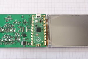
    As of writing this log, the RISA electronics has been assembled, and the mechanical parts have been designed. Only basic software test have been written.

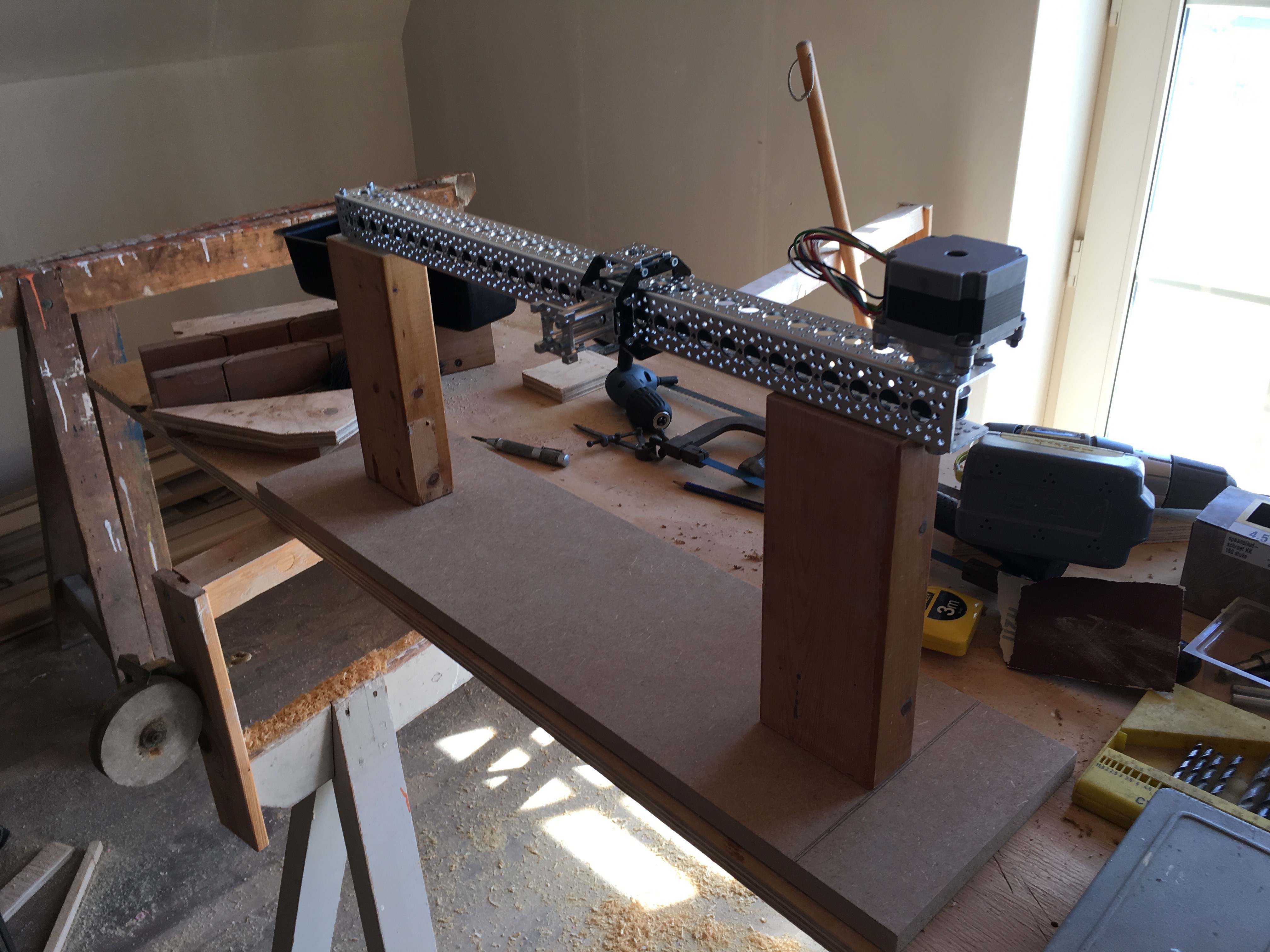
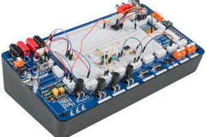
    Figure 1: A partially build base.

    I have even 3D-printed some prototypes of the parts, but I will have to print a new revision for the final project. The reason I haven't printed this revision yet, is that I needed to my laptop to write these logs, instead of it being tied to a printer. The slider and base have also been assembled.

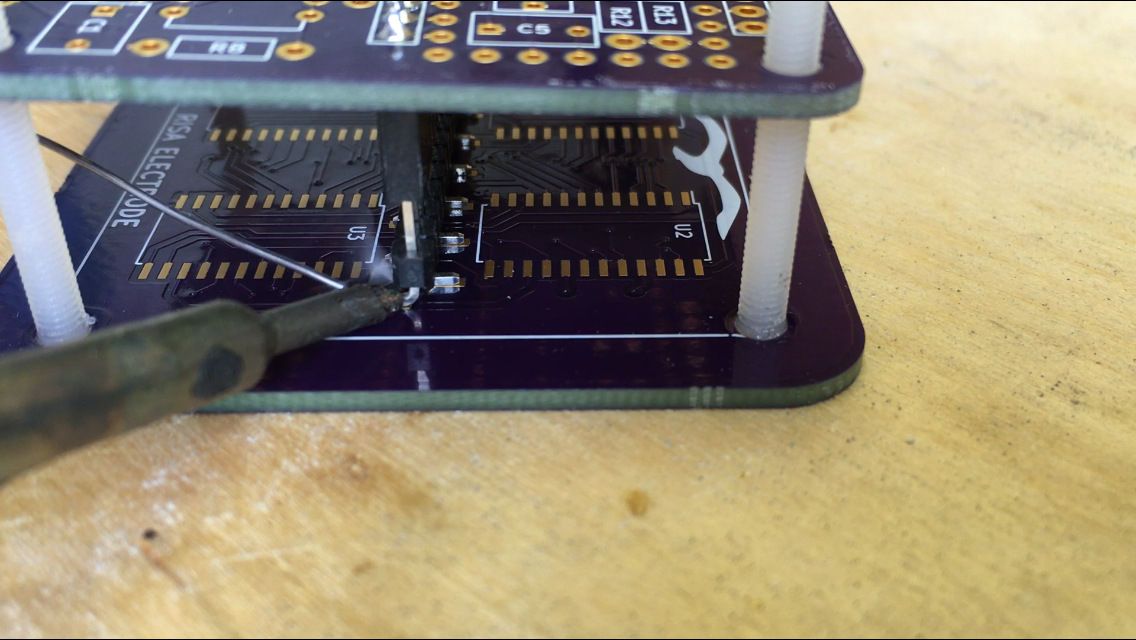
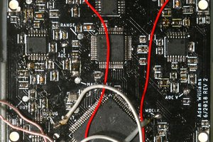
    Figure 2: A picture from the electronics build process.

    The last few days, I have focussed on actually documenting the project a bit. Since I like to write quite extensively, this has meant that the documentation has sucked up all my time. I have now documented most of what was done until now, except for the build process however. This means that I will resume working on the core of the project next, and then document the new stuff as I finish it, with one exception: I have gathered quite a lot of images of the build process, so I will probably also start writing some of that.

    Anyhow, those are the plans, I hope you'll enjoy the documentation of the project!

  • DAC with DMA and buffer on a Teensy 3.2

    Arthur Admiraal07/10/2016 at 14:12 2 comments

    Although I haven't started programming the main program for RISA yet, I have done some tests. For one of them, I tried to get the DAC working. Since the main application will have to both read out two ADCs and write data to the DAC, I want to try to decouple as much as I can from the processor. Hence, I tried to get the DAC working with its internal buffer and Direct Memory Acces (DMA). I couldn't really found a tutorial on how to do this, so it took while. Because of that, I figured I would write up one of my own here.

    Read more »

  • Electronics details

    Arthur Admiraal07/08/2016 at 13:01 0 comments

    foIn this log, let's examine the electronics of the Rapid Impedance Spectroscopy Array, RISA.

    Read more »

  • Old problems, new solutions

    Arthur Admiraal07/07/2016 at 19:12 0 comments

    In the last log, I briefly mentioned what I think were the problems in my old setup to research the influence of flow speed on the electrical behaviour of electrolytic solutions. In this log, I want to go over these problems and discuss the high-level design choices I made to alleviate them.

    Read more »

  • Prior research

    Arthur Admiraal07/07/2016 at 13:15 0 comments

    In this log, I will try to succinctly explain the information I have gathered on flow-dependent electrical behaviours of electrolytic solutions in basic terms.

    Read more »

View all 6 project logs

  • 1
    Step 1

    ! These build instructions are still work in progress. More elaborate instructions, including better imagery will be added later, and the instructions may contain errors. Please only use these for educational purposes for the time being !

    Buy the parts and gather the tools! A more extensive list of the tools you'll need will appear here later, but you are going to need at least:

    • A soldering iron suitable for doing coarse pitch smt soldering
    • A drill
    • Countersinking drill bits
    • Various small diameter drill bits
    • A file
    • Some screwdrivers
    • A 3D printer
    • Some glue
    • Various pliers

    You also need to be able to solder. For that I recommend watching this great tutorial.

  • 2
    Step 2

    Assembling RISA

    (I occidentally forgot to do this and did this in a later moment in the build, which is why the images are a bit inconsistent)

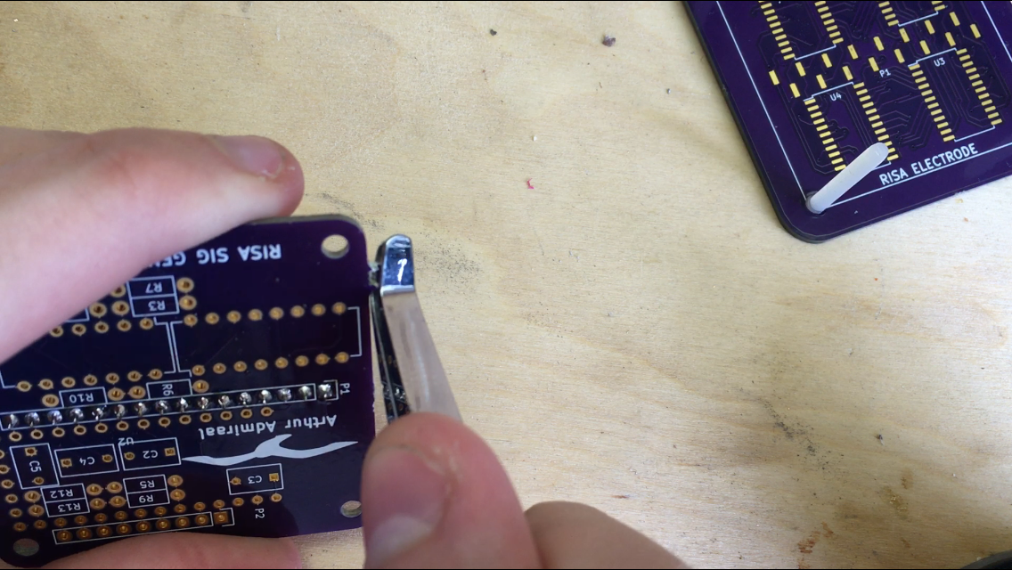
    If you got your PCBs from OSH Park, they may have some mouse bites at the edges. Break those of using your pliers:

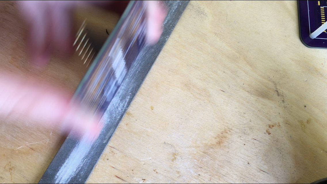
    Now, file the sides of the PCBs down so that they are flat.

    Please observe proper safety measures for the FR4 dust that may result from this operation, and that may be harmful for your lungs.

  • 3
    Step 3

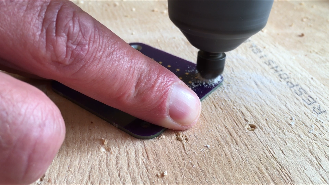
    Countersink the holes in the electrode PCB so that the countersunk M3 nylon screws fit in precisely. This is to minimize distortions in the flow over the electrodes. Make sure to check repeatedly for that perfect fit. I asked my father to help me out here, because I don't have that much experience with mechanical stuff, so he showed me how to do it:

    Again, please observe proper safety measures for the FR4 dust that may result from this operation, and that may be harmful for your lungs.

View all 10 instructions

Enjoy this project?

Share

Discussions

Similar Projects

Does this project spark your interest?

Become a member to follow this project and never miss any updates