-
1Step 1
! These build instructions are still work in progress. More elaborate instructions, including better imagery will be added later, and the instructions may contain errors. Please only use these for educational purposes for the time being !
Buy the parts and gather the tools! A more extensive list of the tools you'll need will appear here later, but you are going to need at least:
- A soldering iron suitable for doing coarse pitch smt soldering
- A drill
- Countersinking drill bits
- Various small diameter drill bits
- A file
- Some screwdrivers
- A 3D printer
- Some glue
- Various pliers
You also need to be able to solder. For that I recommend watching this great tutorial.
-
2Step 2
Assembling RISA
(I occidentally forgot to do this and did this in a later moment in the build, which is why the images are a bit inconsistent)
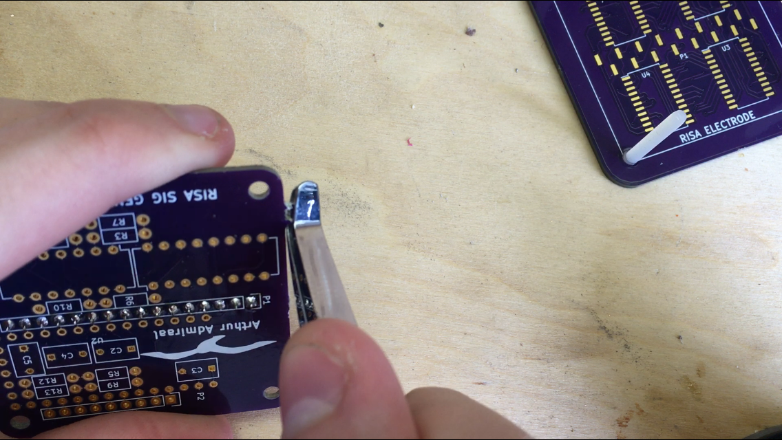
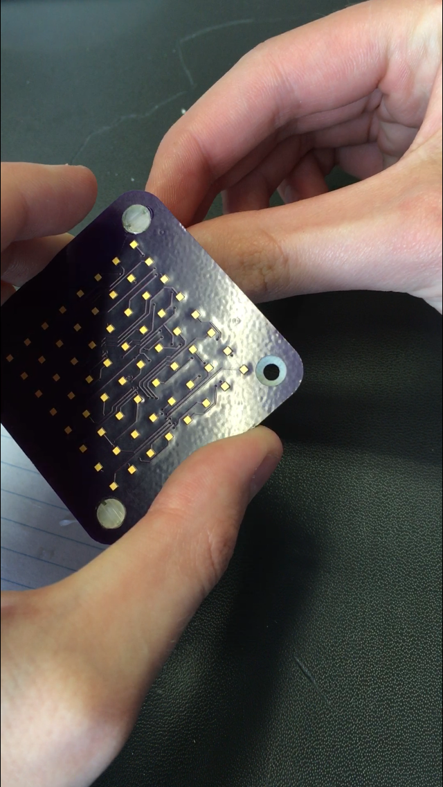
If you got your PCBs from OSH Park, they may have some mouse bites at the edges. Break those of using your pliers:
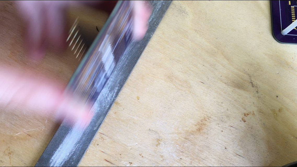
Now, file the sides of the PCBs down so that they are flat.Please observe proper safety measures for the FR4 dust that may result from this operation, and that may be harmful for your lungs.
-
3Step 3
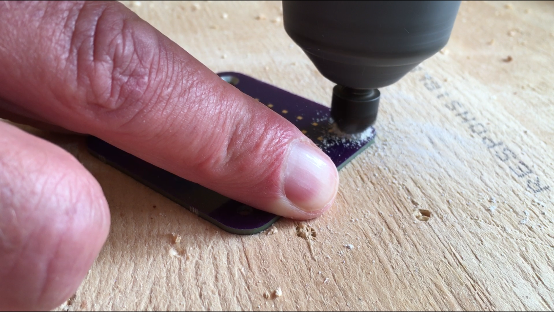
Countersink the holes in the electrode PCB so that the countersunk M3 nylon screws fit in precisely. This is to minimize distortions in the flow over the electrodes. Make sure to check repeatedly for that perfect fit. I asked my father to help me out here, because I don't have that much experience with mechanical stuff, so he showed me how to do it:
Again, please observe proper safety measures for the FR4 dust that may result from this operation, and that may be harmful for your lungs.
-
4Step 4
! Make sure the glue isn't to strong, as we will be breaking the bond later. I used regular all-purpose glue, and it came apart quite easily !
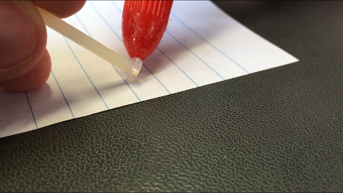
Glue the M3 Nylon countersunk screws to the electrode PCB. Do this by first putting a big dab of glue on the head of the screw...
...and then twisting the screw in the PCB, pulling on it until the glue sets.
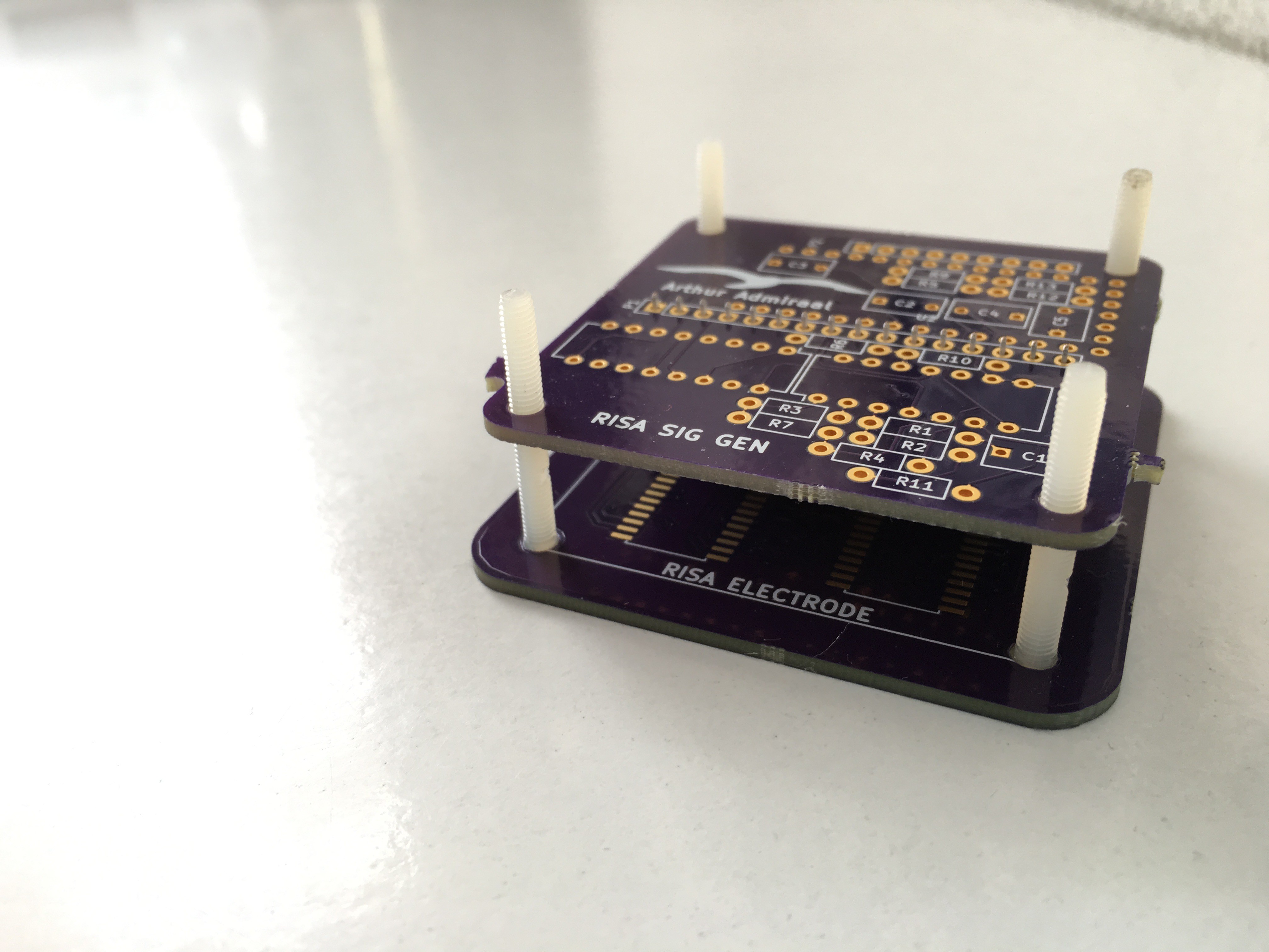
You can wipe away any excess. You may want to put the signal generator PCB on top, with the connectors in between and sit the boards flat to make sure the glue bonds dry so that the screws are perpendicular to the PCB.
-
5Step 5
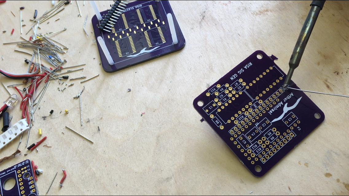
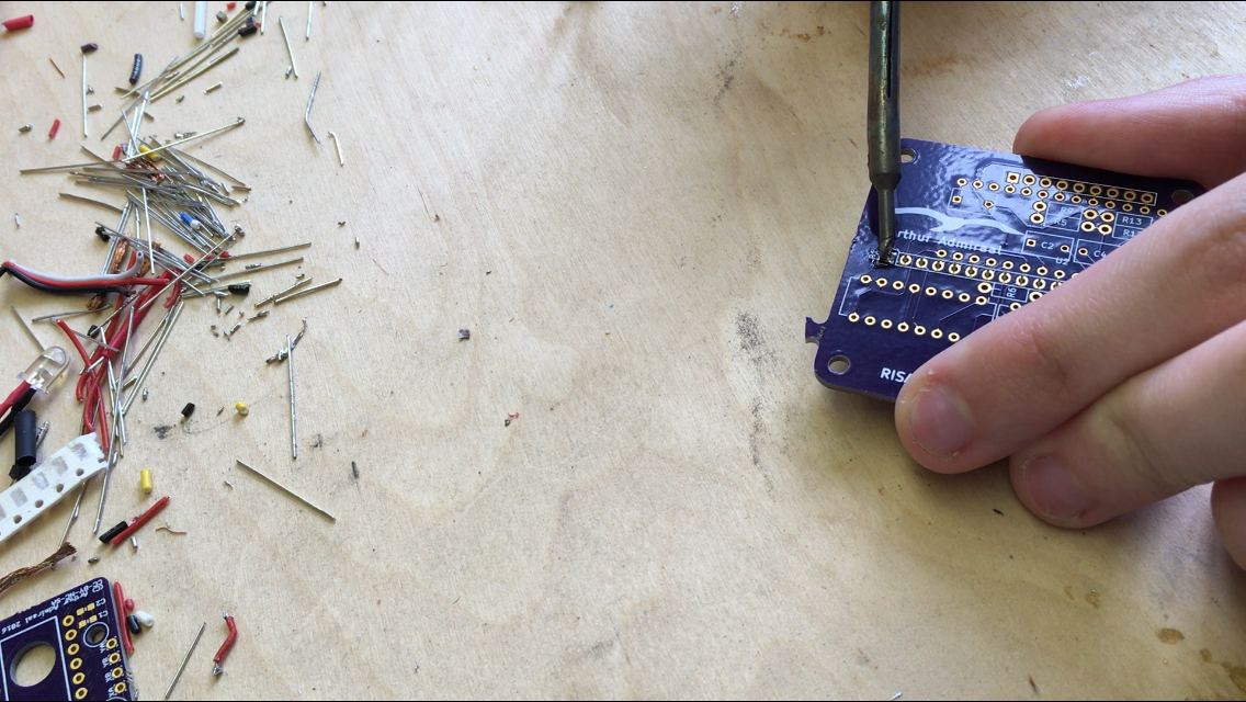
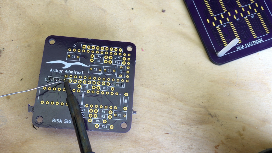
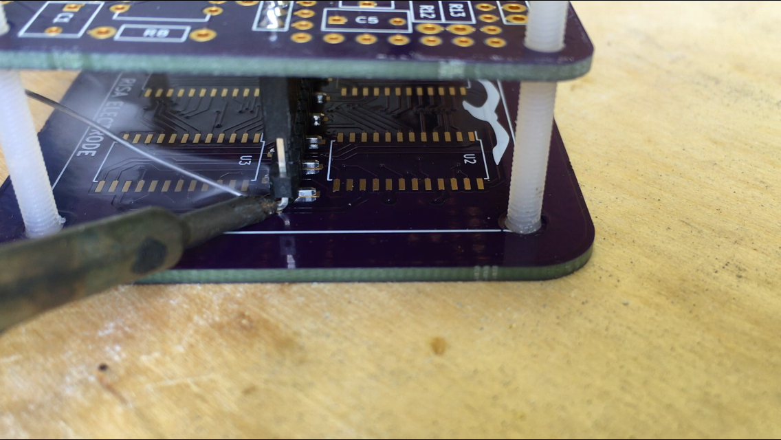
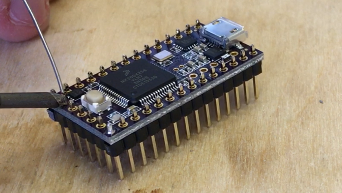
Solder the .1" Header to the bottom of the signal generator PCB. We will be using it to align the smt header on the electrode PCB. First, tag one of the pins:
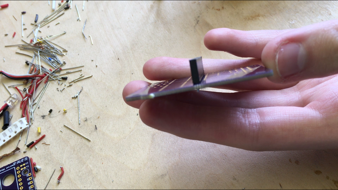
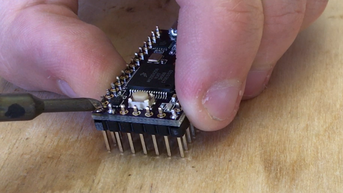
Then, align the header perpendicular to the PCB. You can do this by remelting the solder on the pin you tagged, and pressing down on the PCB. Since the header has a flat underside, it will tend to align itself perpendicular to the PCB, although you have to do a bit of fine-tuning by balancing the PCB yourself.
The header should end up being almost perfectly perpendicular:
You can now solder the remaining pins:
Make sure to do this step in a well-ventilated area, since the fumes coming off this process can be harmful for your lungs.
-
6Step 6
Lightly put the male header in the female header. We will be soldering it to the electrode PCB in this step.
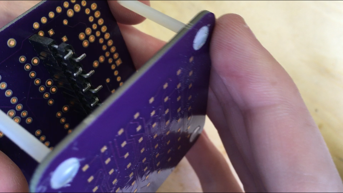
Now make sure your glue has set, and put the electrode PCB on the screws of the signal generator PCB. Make sure the seagulls and text have the same orientation on both PCBs. The screws now help us to align the connector, so that the PCBs will fit together in their enclosure.
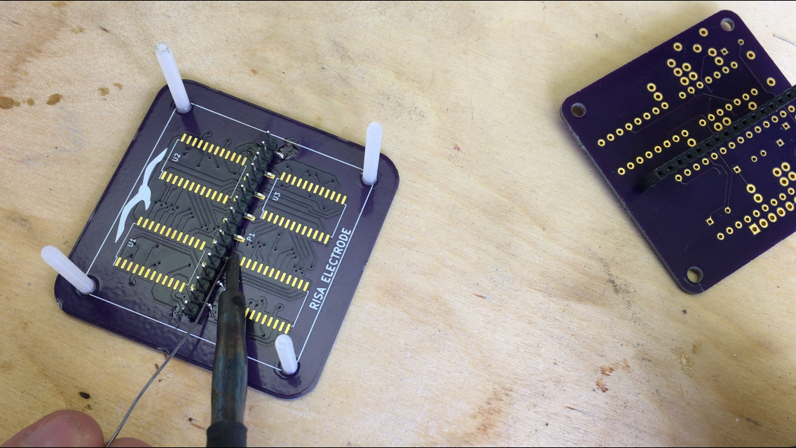
You can wiggle the header a bit to align it to the SMT pads. If everything looks all right, go ahead and tag a pin of the header to the electrode PCB. It helps to also tag down the pin a half turn away. As with all SMT soldering, adding some flux may help you here.
You can now remove the signal generator PCB and solder down all the pins. This would be a great point to break the glue bond of the screws by providing some light pressure on them and wiggling them around.
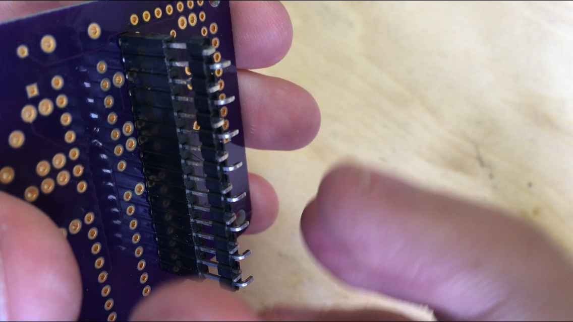
You should now have both headers soldered and neatly aligned.
Make sure to do this step in a well-ventilated area, since the fumes coming off this process can be harmful for your lungs.
-
7Step 7
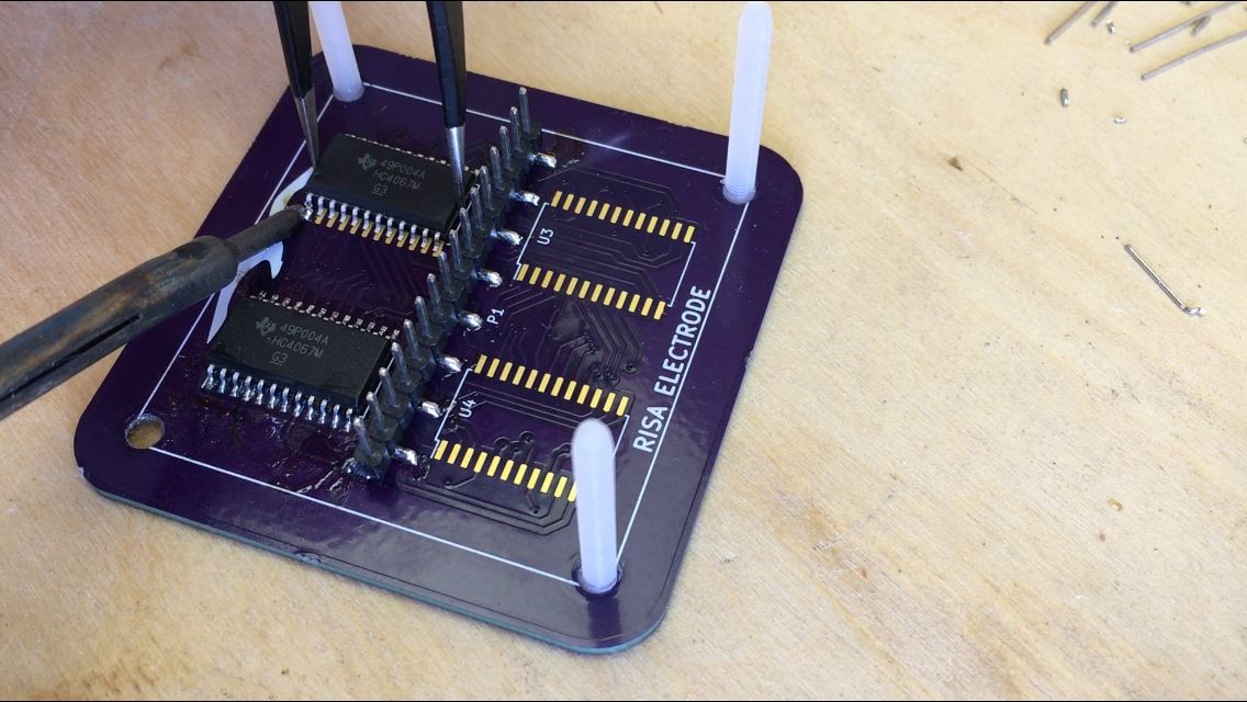
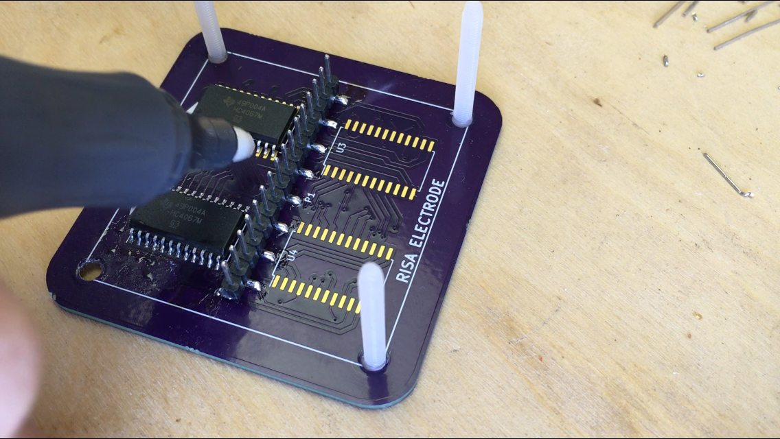
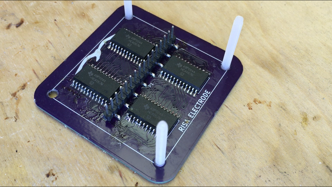
Now, solder on the 4067 ICs. The easiest way to do this is probably to first put down some solder on a corner pin:
Then you can remelt this solder and slide in the chip, so that it is perfectly aligned. Note that pin 1 should be on the side of the reference indicator text ('U2', for example) on the silkscreen.
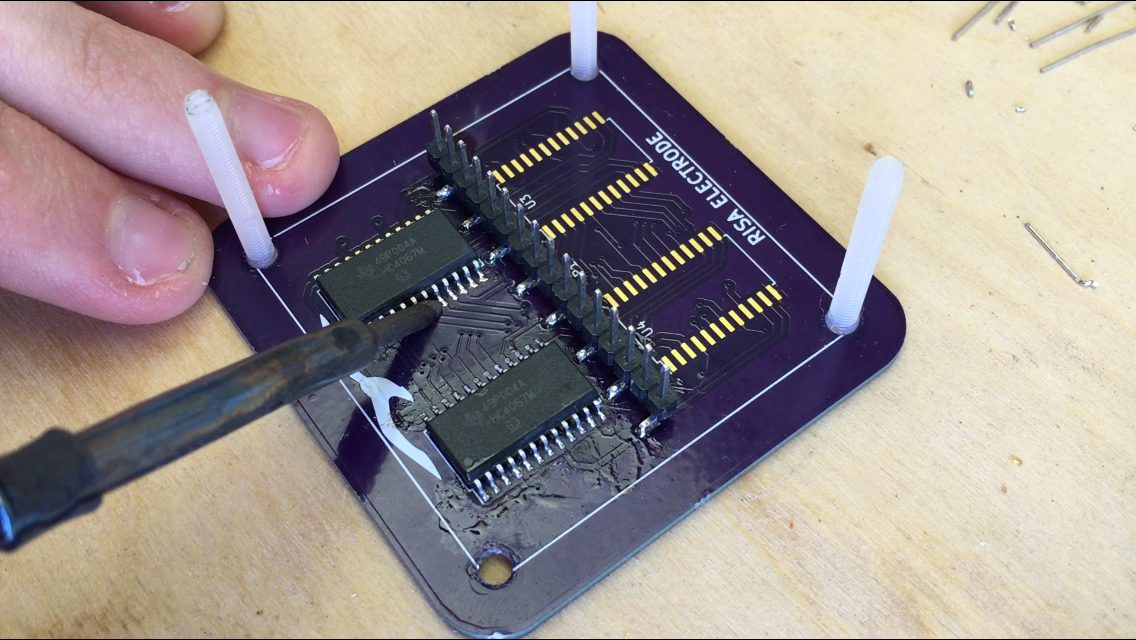
Now put some flux on the leads of the IC using your favourite application method:
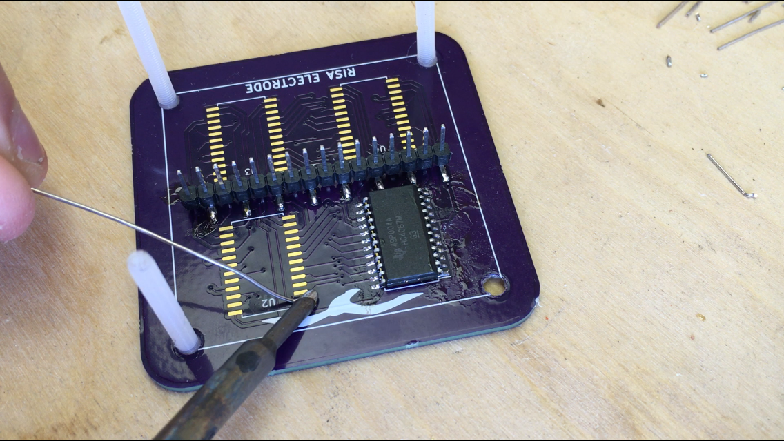
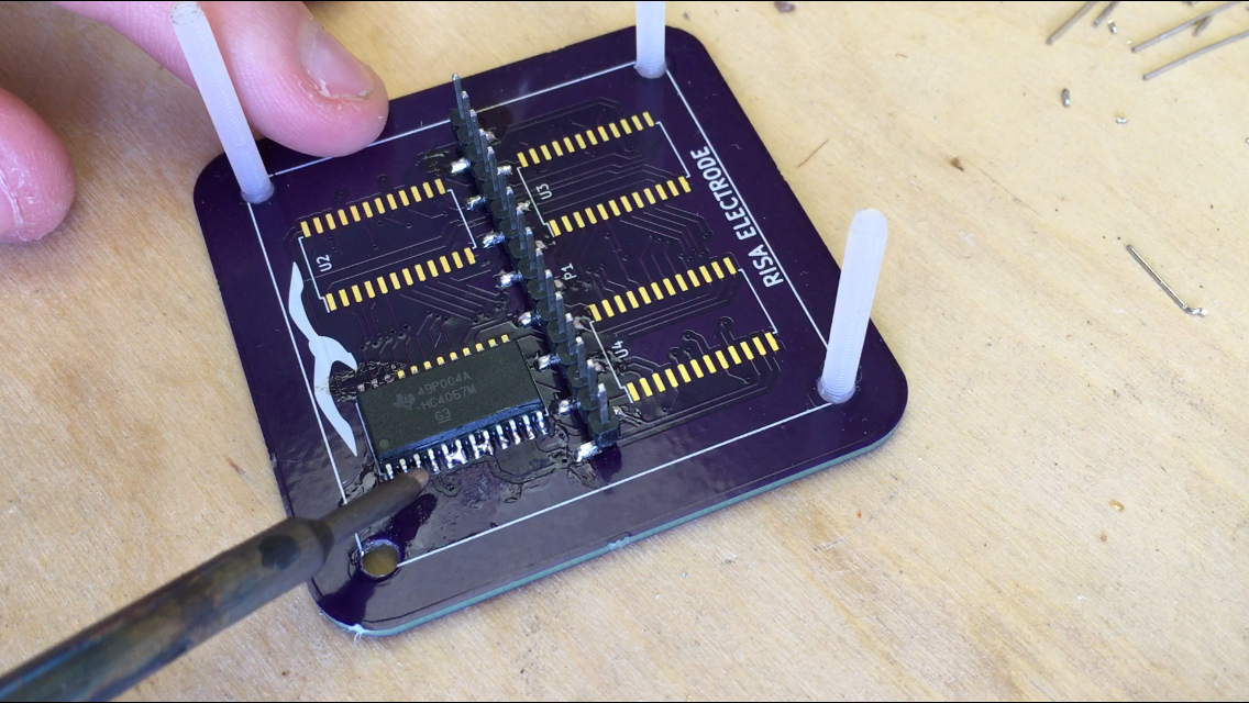
Now put some solder on the tip of you soldering iron, and drag along the leads. This technique is called 'drag soldering', and allows you to quickly create very nice-looking solder joints. Again, it would've helped me a lot if I had removed the screws, but sadly I did not.
Make sure to check for solder bridges. If you see any: don't panic! Most of them can be removed by adding some flux and dragging away from the chip with a clean tip.
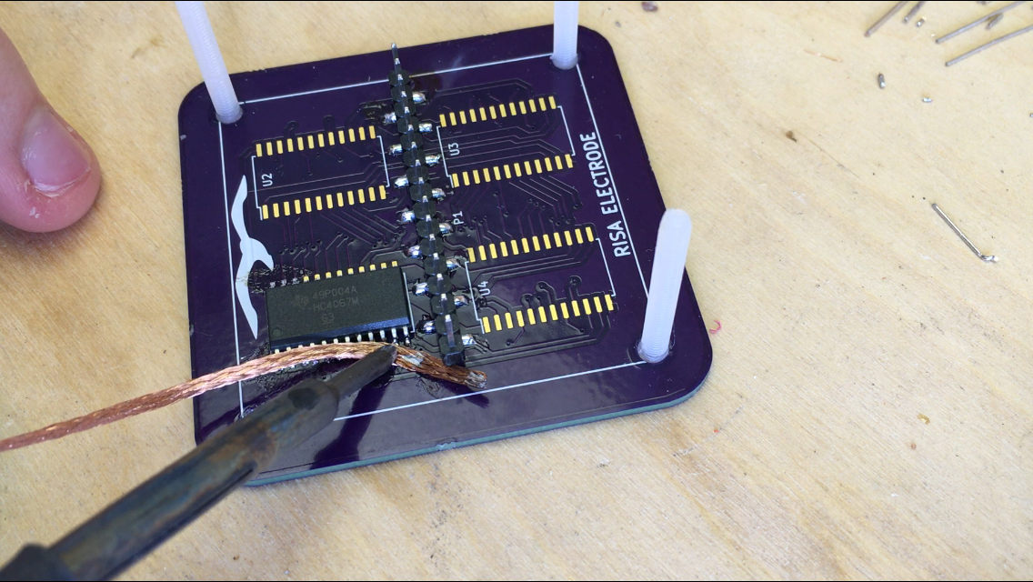
If that doesn't work, you can use some solder wick to wick the solder off. Be sure to do some drag soldering after that to replenish the solder on the pins, to remake the connection.
All that you have to do now is repeat those steps until you have a fully soldered electrode PCB!
Make sure to do this step in a well-ventilated area, since the fumes coming off this process can be harmful for your lungs.
-
8Step 8
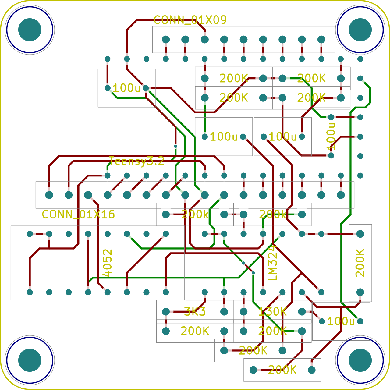
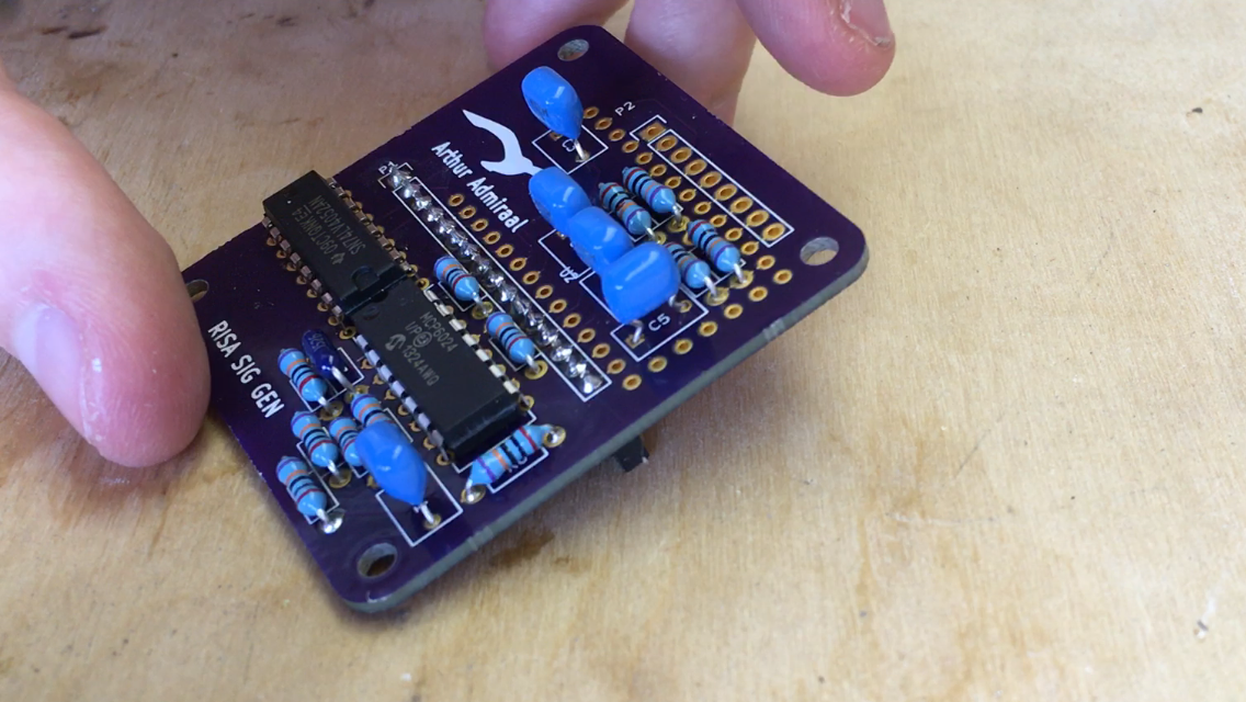
Solder the signal generator board together. You can use the component guide below to figure out where to place what component.
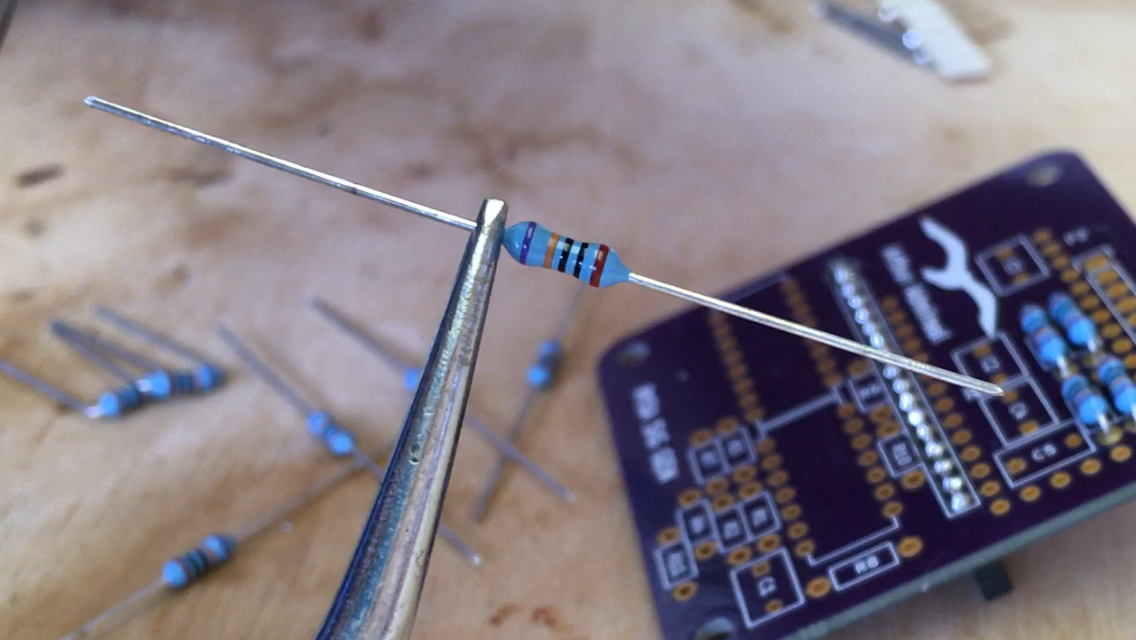
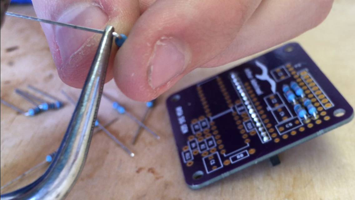
There are some things to keep in mind while assembling the PCB. First up, the footprints for the resistors are really tight, so that it is difficult to place them. To solve this issue, take a pair of pliers and bend the leads of the resistors as tightly as possible, right where they leave the resistor.
Secondly, the Teensy doesn't come with headers soldered on. To align everything neatly, you can solder down the headers with one solder joint, and then remelt the solder while applying light pressure to the bottom of the header to align it.
Lastly, all components go on the opposite site of the header you soldered earlier.
Using these techniques, you should have the board assembled in no time.
* Not a fully assembled board, the headers on the topside still need to be soldered in.
Make sure to do this step in a well-ventilated area, since the fumes coming off this process can be harmful for your lungs.
-
9Step 9
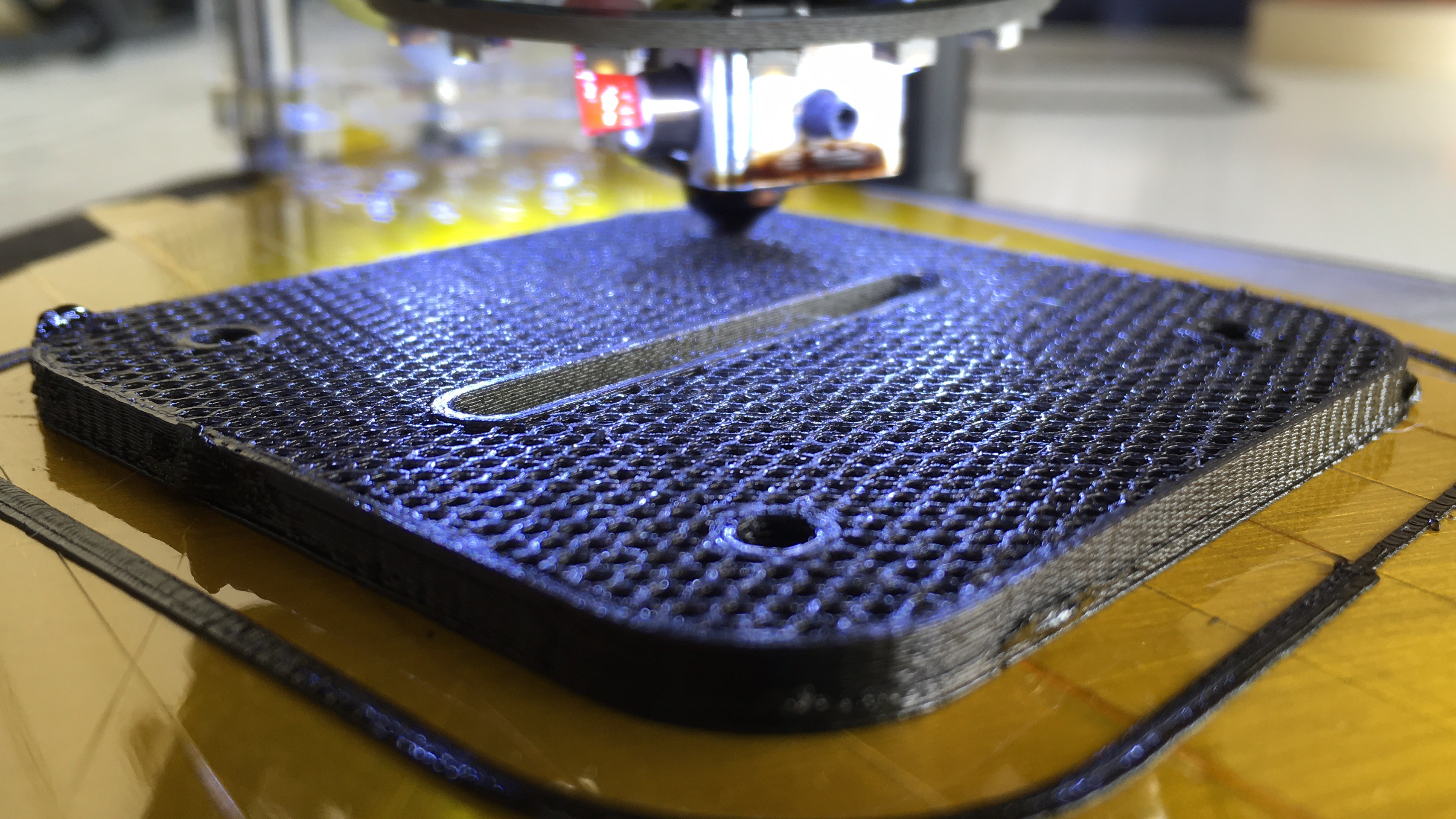
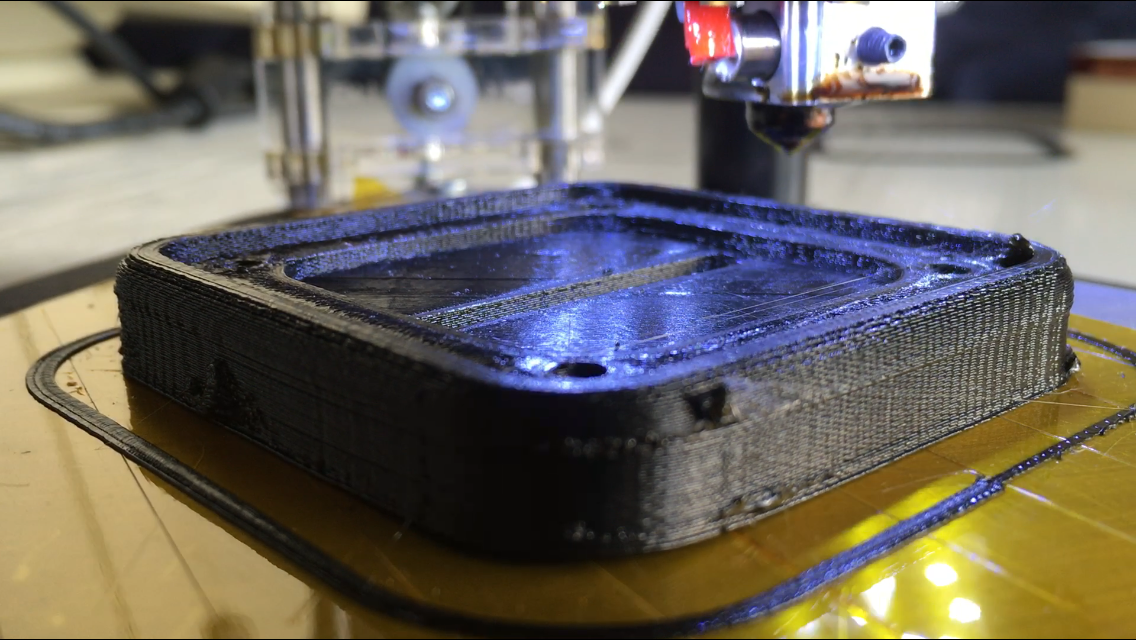
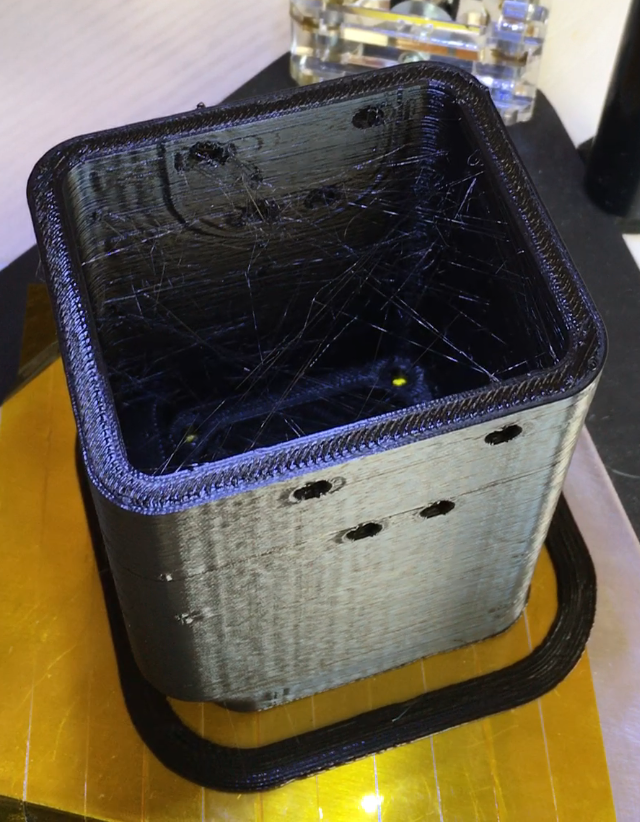
3D-print the case for RISA. I am personally using a μDelta 3D printer. I don't have that much experience with 3D-printing, so my prints didn't come out very nice, but that doesn't matter.
For me, printing the parts involved loading the .stl files, which you can find in the GitHub repository into Repetier and hitting print. I printed the electrode holder part with a layer height of 0.1mm and at the slow speed setting, but printed the main part of the case at a layer height of 0.3mm at the normal speed. Both parts were printed in PLA. Each print took about 4 hours.
The end result were these parts:
![]()
-
10Step 10
Wait for the author to publish more instructions.
Solid state flow sensing using EIS
Investigations into a novel flow sensing technique to create tiny cheap flow sensors, all using electrical impedance spectroscopy.
 Arthur Admiraal
 * Not a fully assembled board, the headers on the topside still need to be soldered in.
Discussions
Become a Hackaday.io Member
Create an account to leave a comment. Already have an account? Log In.