Theia IoT light-switch
An easy, cheap and open source way to add IoT to a light switch.
An easy, cheap and open source way to add IoT to a light switch.
To make the experience fit your profile, pick a username and tell us what interests you.
We found and based on your interests.
MK2 29-09-16.zipThe KiCad files for the MK2 prototype, needless to say that you should add the customparts and customfootprints files to the respective paths before attempting to open the project files in KiCad. Yes, this text is a shameless copy/paste.x-zip-compressed - 84.98 kB - 09/29/2016 at 15:45 |
|
|
Theia MK0.1 WEISS.zipThe KiCad files for the "WEISS" MK 0.1 prototype, needless to say that you should add the customparts and customfootprints files to the respective paths before attempting to open the project files in KiCad.Zip Archive - 53.99 kB - 08/15/2016 at 18:37 |
|
Its been a little while since I last updated. A levels and sixth for life has kind of taken over at the minute, lots of work to do, but I still found the time to solder up the rest of the prototype.
Having a few problems at the minute though, the ESP8266 I bought might be busted... or maybe my PCB design was bad. I'll tinker around with it a bit more and see whats up with it. So until the next log, David out.
This is a kind of "behind the scenes" of how I made the entry video.
To clear a few things up, it looks amateurish because it is. I don't have Sony Vegas or any other such software, and I certainly don't have a camera that can take high quality footage.
I used OpenShot video editor for all the video editing (I couldn't stand using Windows Live Movie Maker), and I used MS Paint for the logo and captions.
After taking all the footage with my camera, I looked at the EXIF data to see what resolution it was, and used that as a guide to what size the captions and logo should be. I then set the size of the canvas in MS Paint to 1280 x 720. Next, I found the centre, using 2 pink line, each being 2 pixels thick.
I then created a series of blocks, all 60 pixels by 60 pixels, with 4 pixels spacing between them. I then marked the ones to be removed in grey and I rounded off the corners of the blocks to be kept. This was all done by hand (save for some copying and pasting), as I was unable to find a large image of the Hackaday 2016 logo. I guess you could say its pixel art to the next level. P.s. the other coloured lines are just reference markers that I use to keep track of distances.
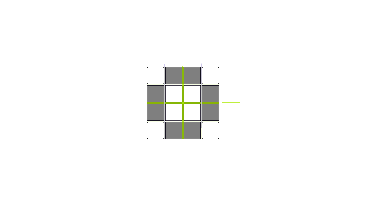
I then proceeded to remove the coloured lines and unnecessary boxes, and colour the background black. I also used a grey colour on the corners of the boxes to make it look rounder (pixel art trick). I went to my project page, hit "F12" on my keyboard and went into the CSS to check what font was used on the title (Helvetica Neue). I then downloaded and installed said font so I could use it from within MS Paint to create the title and subheading above and below the Hackaday Prize 2016 logo.

All-in-all, it took me a around thirty-ish minutes to make the logo - I'm pretty proud of it as well.
The slides were made in the same manner, with the same font, with the textbox retracted from each side by 200 pixels to make it look nice and centred.

It's been a few days since I last posted an update, things are mostly going well. Almost all the parts have arrived, and I have successfully started assembling a prototype. Although, there have been a few setbacks, frying my Arduino being one of them, but other than that things are looking pretty good. I'm surprised a project such as mine has even made it this far, it truly has exceeded all my expectations, and then some.
As you can see, I managed to work around my problems in a hacker-ish fashion; by rounding off the pins on the relay with an emery board (for filing finger-nails), and instead of mounting the screw-down connectors directly to the board - I instead mounted them onto connectors that would fit.
The next important thing I need to do is release a video, still deciding on how i'm gonna do it. I think i'll look at what people have done in previous years and let that help me decide.
Some of my parts came today, including the relays. Although, it wold appear that I have made a slight error - two of the through-holes on the board are too small for the relay pin, and upon further inspection the same goes for the screw-down terminals.
These errors have now been amended on the files hosted both locally on this Hackaday project and on GitHub.
Unfortunately, with some of the parts not fitting, I will have to order the boards again unless I can bodge it somehow. I think i'm going to try and file down the pins so they fit, I that doesn't work I will just have to order again.
They're here!
Hopefully it will still be small enough to fit inside a UK back-box with all the components soldered on.
Of course, they're OSH Park PCB's - great service for small prototype orders.
Next, I have to wait for the rest of the parts to arrive so I can assemble and test the prototype, and get some code running whilst I am it. Hopefully more updates soon!
For now...
Front:
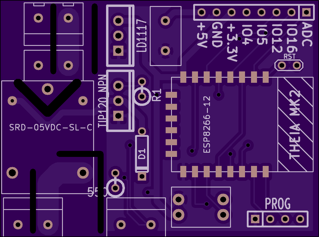
Back:
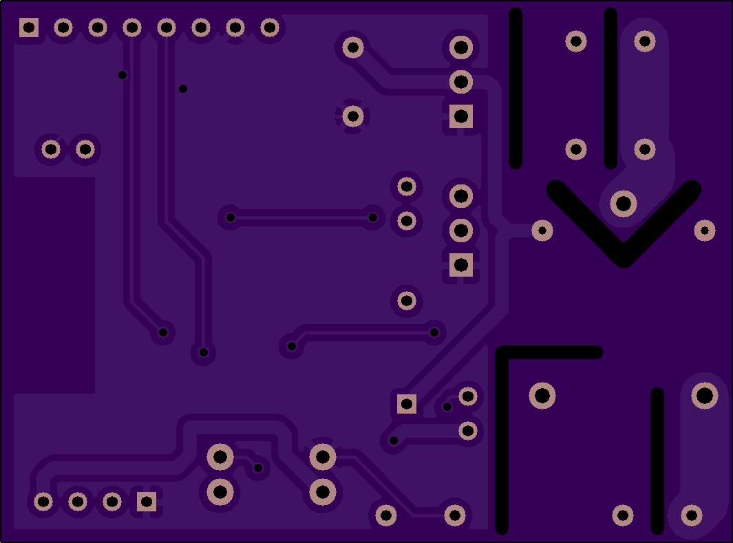
Update:
Prototype board is now ordered, should be arriving soon!
I have decided that instead of 0.2, this revision will be titled as MK2. SO, without further ado...
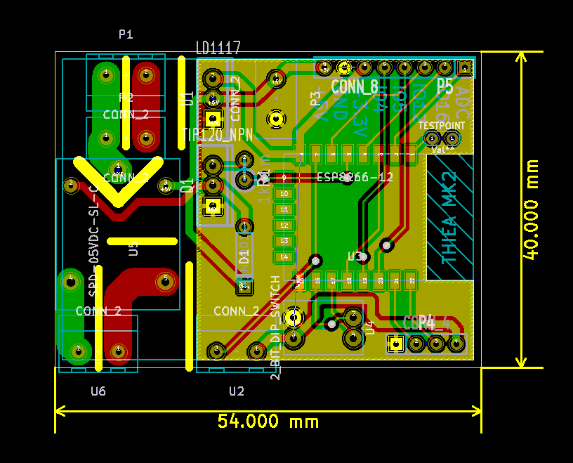
The files will be uploaded here as well as on the GitHub page.
(Note: I just noticed I spelled "Thiea" wrong, but it's corrected in the files)
The updated schematic for the MK0.2 is ready! I have offloaded the PSU to a 3rd party board, and I have switched out a few parts that weren't up to scratch.
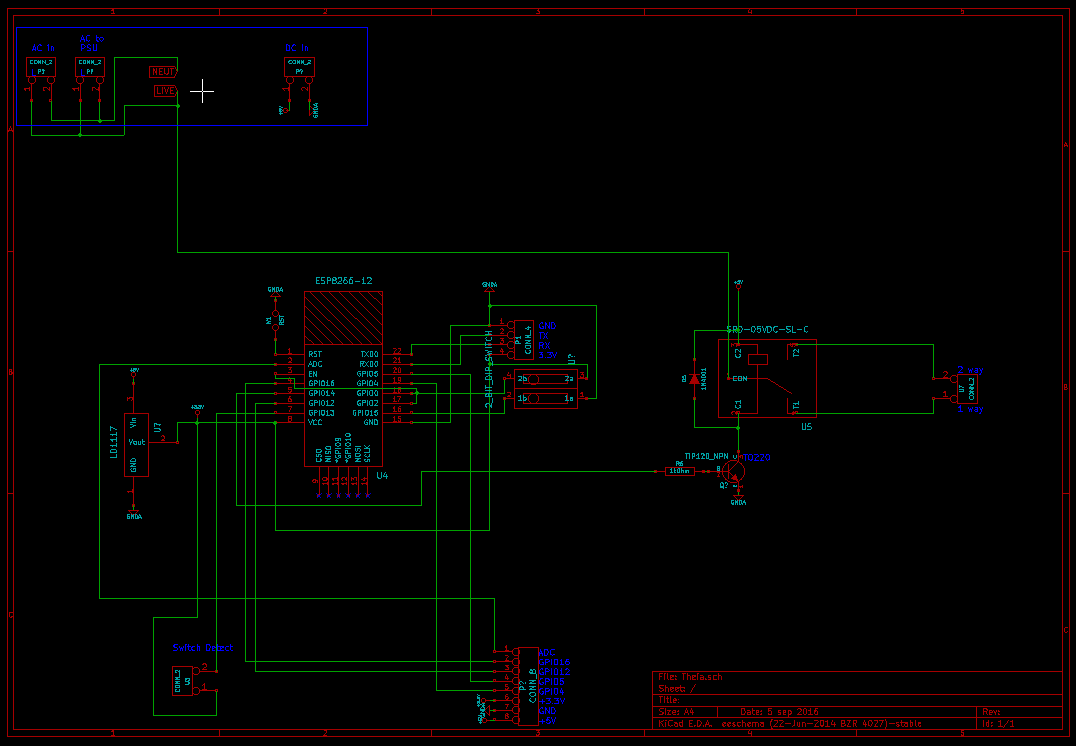
Still, no suggestions as for a nickname for this version - in case you missed it suggestions are welcome!
I have now moved onto designing the PCB, i'll let you know when i'm done!
Thanks to some helpful advice from [Krunal], I have decided to use a third party board to handle the supply of power, I will also be skipping straight to this prototype, which will be mostly the same save for this change to it PSU. It will be aptly marked as 0.2, but I am leaving the decision of its name up to you, Just comment what you think it should be named and I will peruse the comments and pick the most fitting title for this revision.
In case any of you are interested I am intending on using this power supply:

It can be found here. It's the 5V 1A one. More updates soon!
Create an account to leave a comment. Already have an account? Log In.
Sure, I will be using an AC to DC power supply, similar to what mobile phones use to charge. I live in the UK, so I will be converting approx. 230V AC to 5V DC at one amp. I then use a voltage regulator mounted on the Theia PCB to turn the 5V @ 1A to 3.3V @ 0.8 Amps. Does this answer your question? If not, feel free to let me know!
Great work with Thiea!
Did you evaluate Hi-Link HLK-5M05 (http://www.hlktech.net/product_detail.php?ProId=60) for the power supply ? That should fit your needs of 5V, 1A output with a low enough profile to fit inside the UK black-box. There is a good discussion on its sibiling, HLK-PM01 (5V, 600mA), at MySensors forum (https://forum.mysensors.org/topic/1607/safe-in-wall-ac-to-dc-transformers/360). The general consensus being that it is a good option for such circuits. Safety and compliance can be enhanced with a few additional components around it (https://forum.mysensors.org/uploads/files/1438336768013-voeding.pdf). The additional circuitry is designed for HLK-PM01 but can be easily adapted to HLK-5M05.
Another similar option would be Vigortronix VTX-214-005-105 (5V, 1A) (https://www.titan-electronics.co.uk/products/01-577?variant=1094676053).
Admittedly, no I haven't, I will look at that for future revision, thanks for the head-up.
Wouldn't using a triac and opto-triac driver save much more space than a relay?
Quite possibly, I haven't investigated that route yet, I am only trying to get a working prototype out at the minute. I intend to make it more efficient an smaller later on in it's development.
Good work. Your power supply AC-DC converter is rated for 120mA as per datasheet. Whereas ESP8266 itself will be drawing 150-200mA also relay would be drawing 100mA more. In that case your IC will be overheating and restarting many times and power supply will not be constant.
Have you tested it. Please let me know the results.
I noticed this bottle-neck earlier on, but I kept it in as I did not have an alternative at the time. I am now working on the second rev which uses a 3rd party PSU, like the ones used in phone chargers instead.
I would prefer to go for at least 1Amp PSU for smooth operation. I myself working on getting such a thing, but could not find any.
Please let us know if you find such a PSU. Thanks in advance. Good Luck.
Great project - I've been thinking about a switch that works exactly like this one for a while now. Massive advantage over other 'smart' switches: normal people can operate them!
Admittedly, I haven't gone part hunting yet, but I will get back to you when I find out the cost. I know the PCB on it's own will cost £17.83 from OSH Park, other than that I intend to source parts for the prototype from MOuser if I don't already have them.
how do you plan on having the manual switch and the IoT have the same priority? It seems like you either give the manual switch priority or the IoT switch priority?
The manual switch will tell the on-board logic which position the relay should be in, this position can be changed "digitally" without moving the physical position of the switch. When switched digitally it inverts the current state of the physical switch, allowing the physical switch to still change the state of the light. Sorry if it's not very clear, I'm working on some diagrams for the next project log.
just use an XOR logic, I have played with some PLCs for home automation and that works best for two switches with equal priority.
Become a member to follow this project and never miss any updates
 Bulbul
 K Gilbert
 Anthony
 Joe Menard
i didnt understood how do you supply the power to your citcuit, from 220V to 5V and 3.3
can you explain it again please?