 Boian Mitov
-
1Step 1
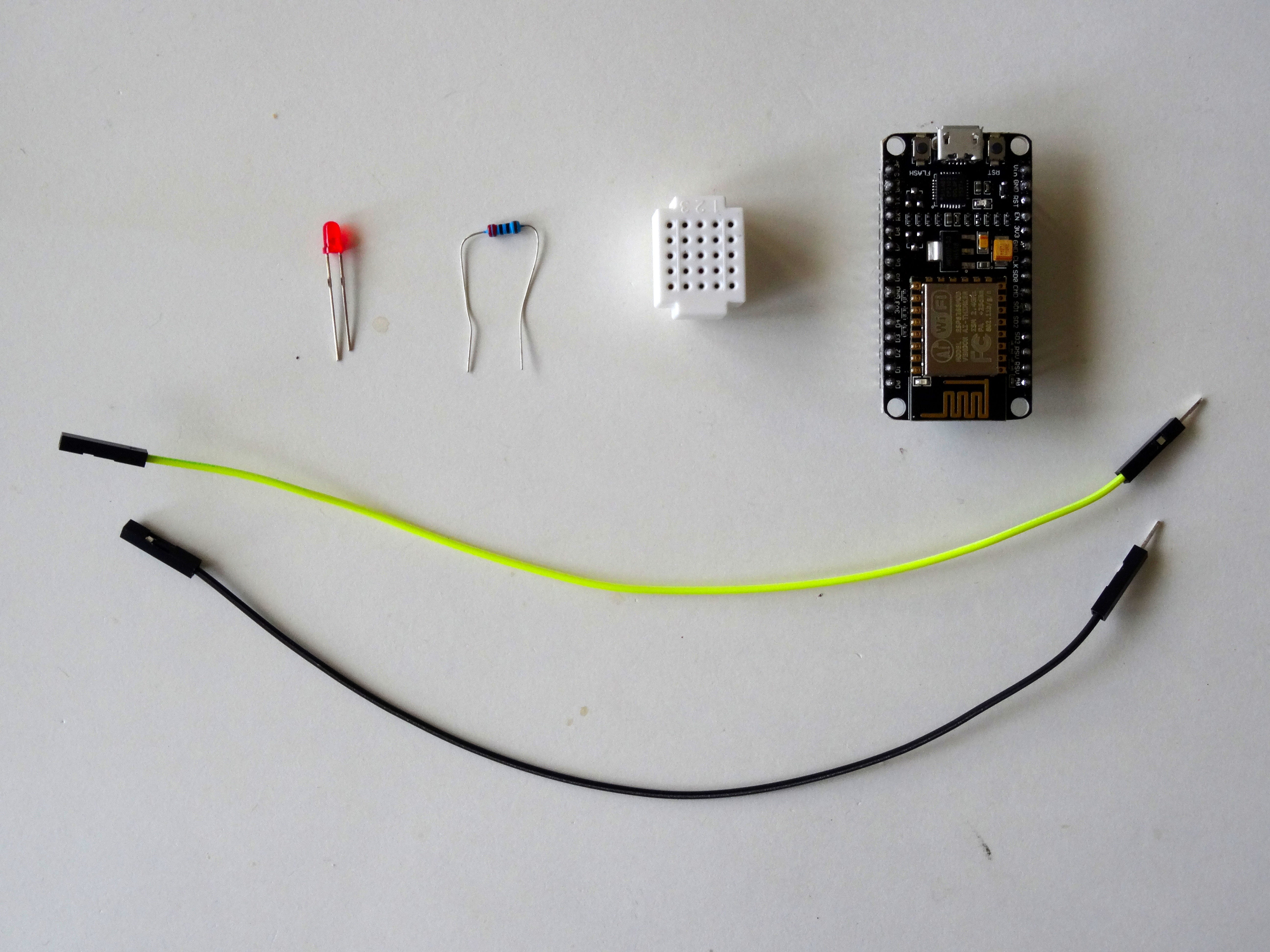
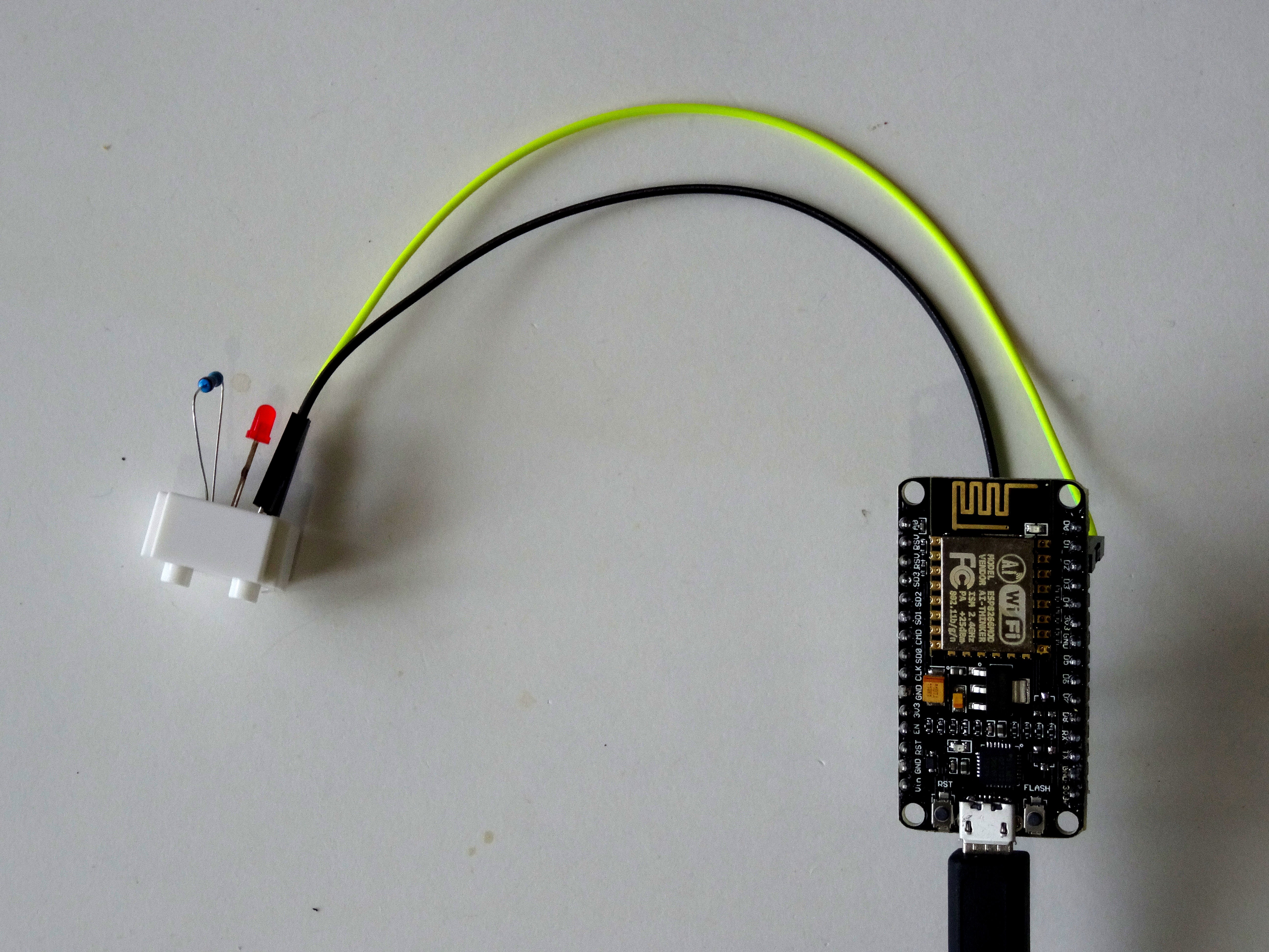
![]() Components
Components- One ESP8266. (I used NodeMCU 1.0, but other versions will also be fine)
- One LED
- One 220 Ohm Resistor
- One Breadboard (I used a Small Breadboard but any other is just fine)
- 2 Female-Male jumper wires
-
2Step 2
Connect the Resistor and the LED
- Place the 220 Ohm Resistor on the Breadboard as shown on Picture 1
![]()
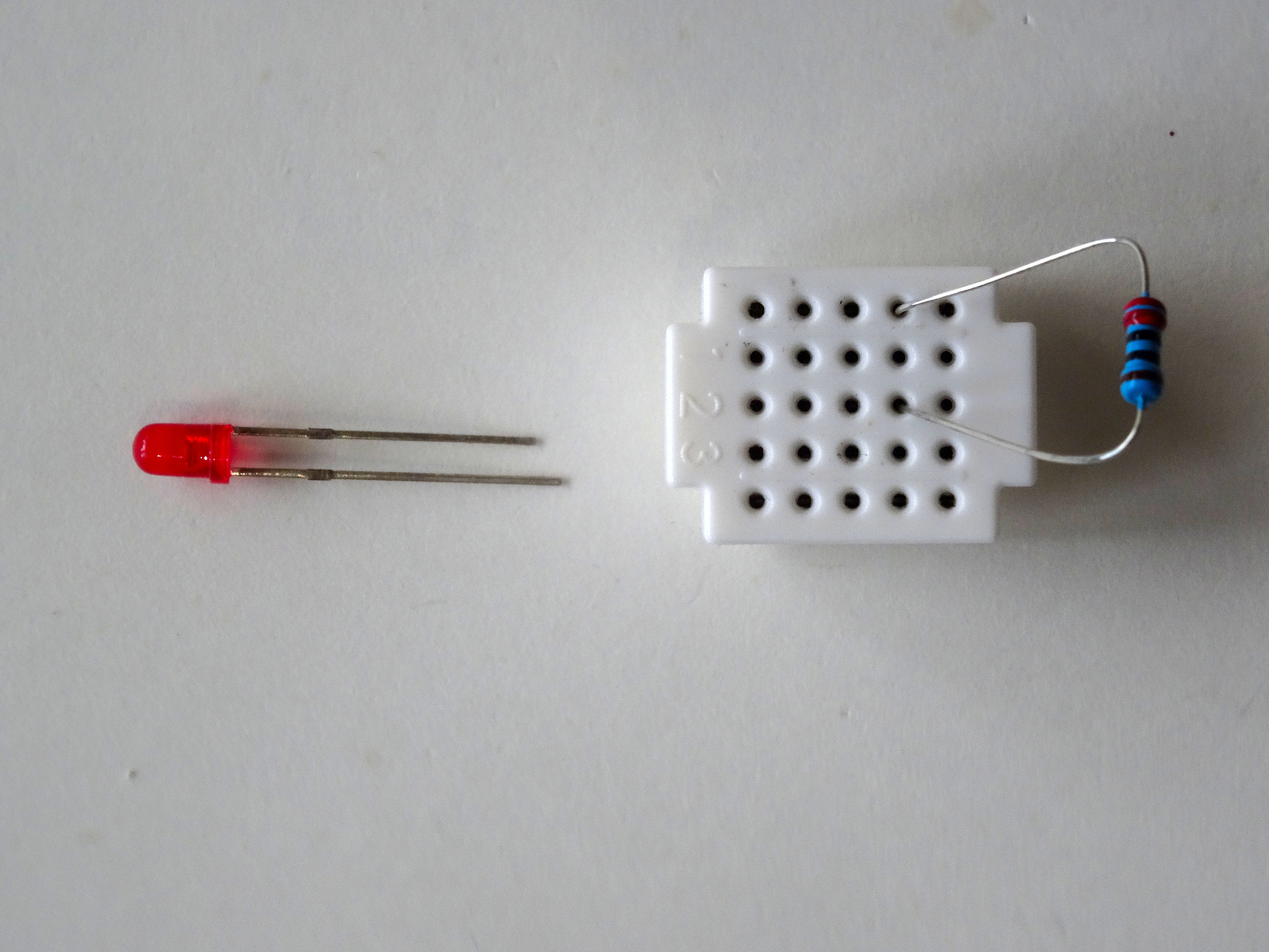
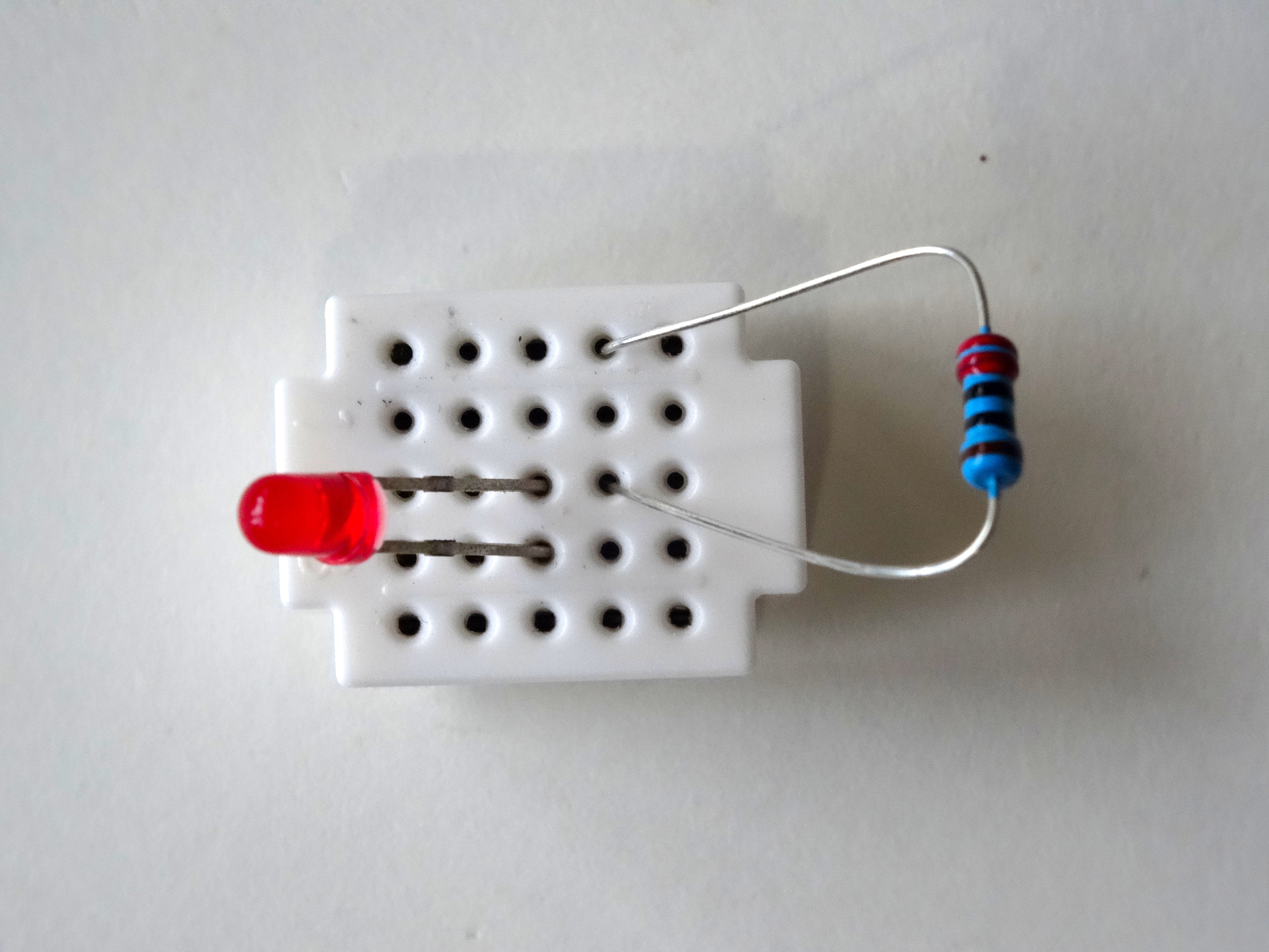
- Connect the Place the LED on the Breadboard so the Cathode end (The shorter one) is connected to one end of the Resistor (Picture 2 and 3)
![]()
![]()
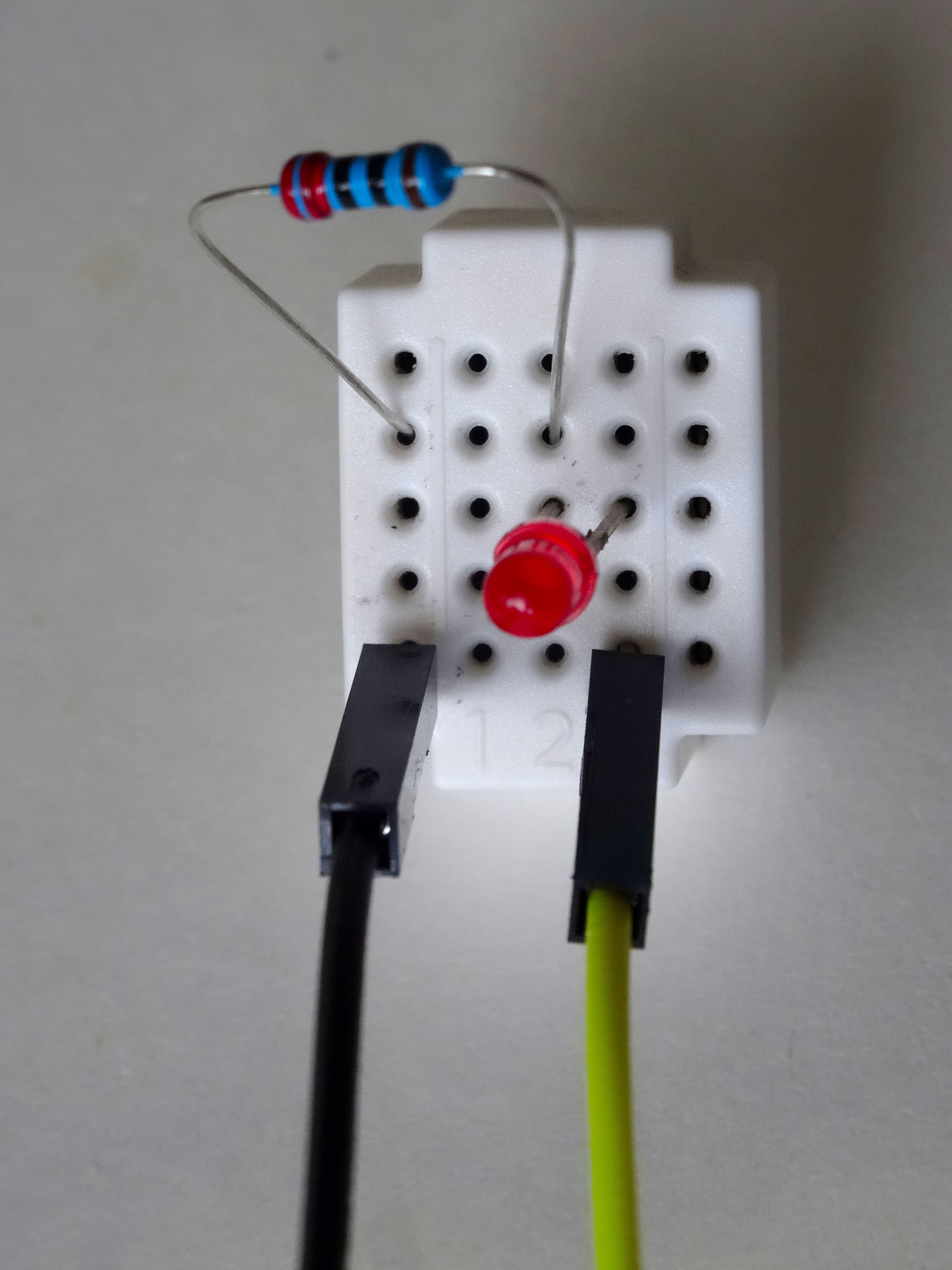
- Connect Ground wire (Black wire) to the other end of the resistor (Picture 4)
- Connect "LED wire" (Yellow wire) to the Anode (The longer end) of the LED (Picture 4)
![]()
- Place the 220 Ohm Resistor on the Breadboard as shown on Picture 1
-
3Step 3
Connect the ESP8266 Module
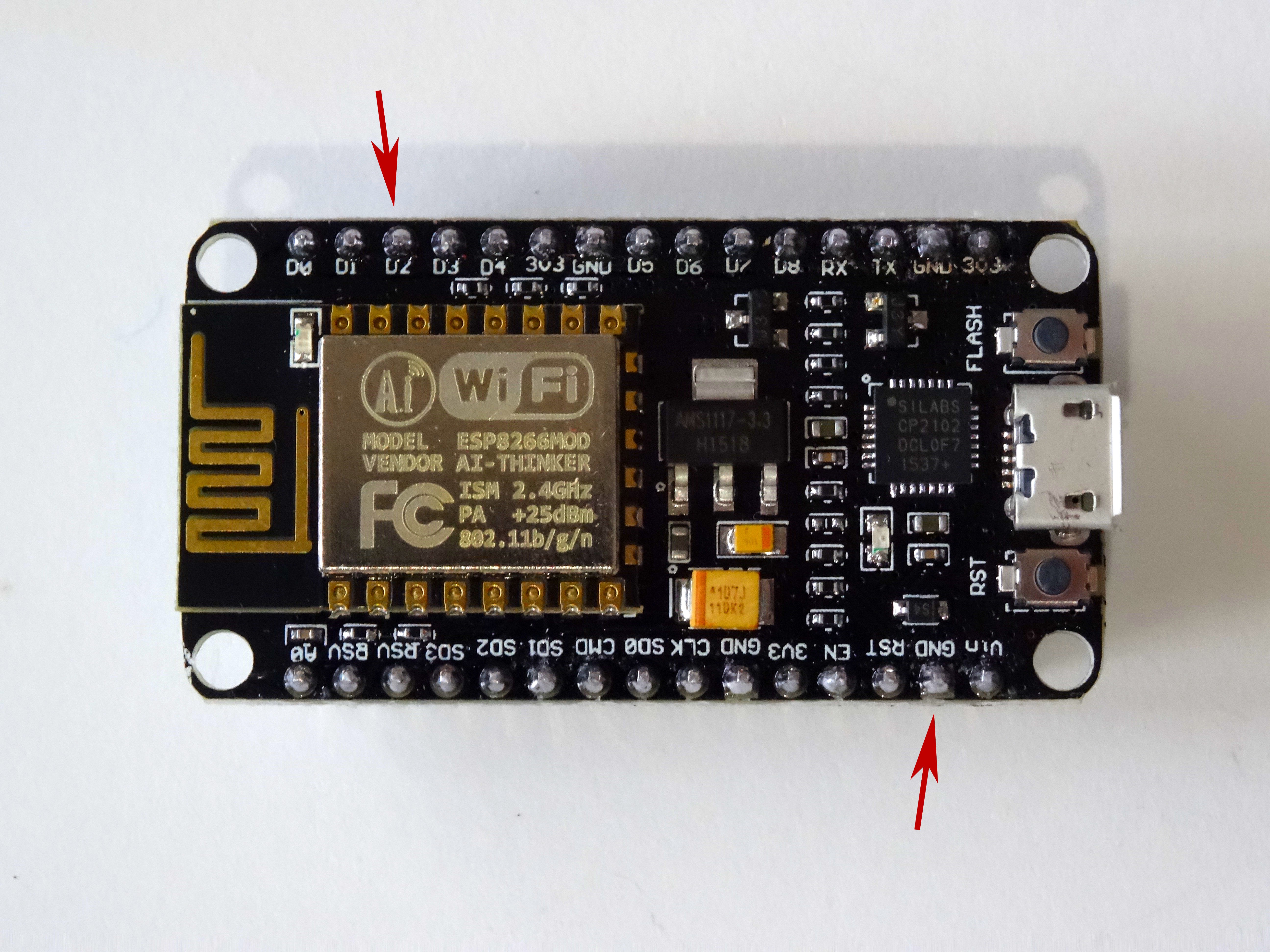
- Connect the other end of the Ground wire(Black wire) to the Ground pin of the ESP8266 module (Picture 1)
![]()
- Connect the other end of the "LED" wire(Yellow wire) to the Digital pin 2 of the ESP8266 module (Picture 2)
![]()
- Picture 3 shows where are the Ground and Digital 2 pins in the NodeMCU 1.0 that were connected on this step
![]()
- Connect the other end of the Ground wire(Black wire) to the Ground pin of the ESP8266 module (Picture 1)
-
4Step 4
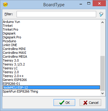
Start Visuino, and select the ESP8266 Board type
To start programming the Arduino, you will need to have the Arduino IDE installed from here: http://www.arduino.cc/.
Please be aware that there are some critical bugs in Arduino IDE 1.6.6.
Make sure that you install 1.6.7 or higher, otherwise this Instructable will not work!
If you have not done follow the steps in this Tutorial to setup the Arduino IDE to program ESP 8266!
The Visuino: https://www.visuino.com also needs to be installed.
-
5Step 5
In Visuino: Add and connect Pulse Generator component
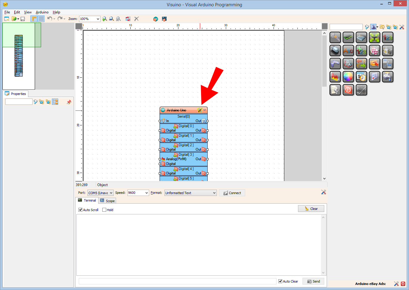
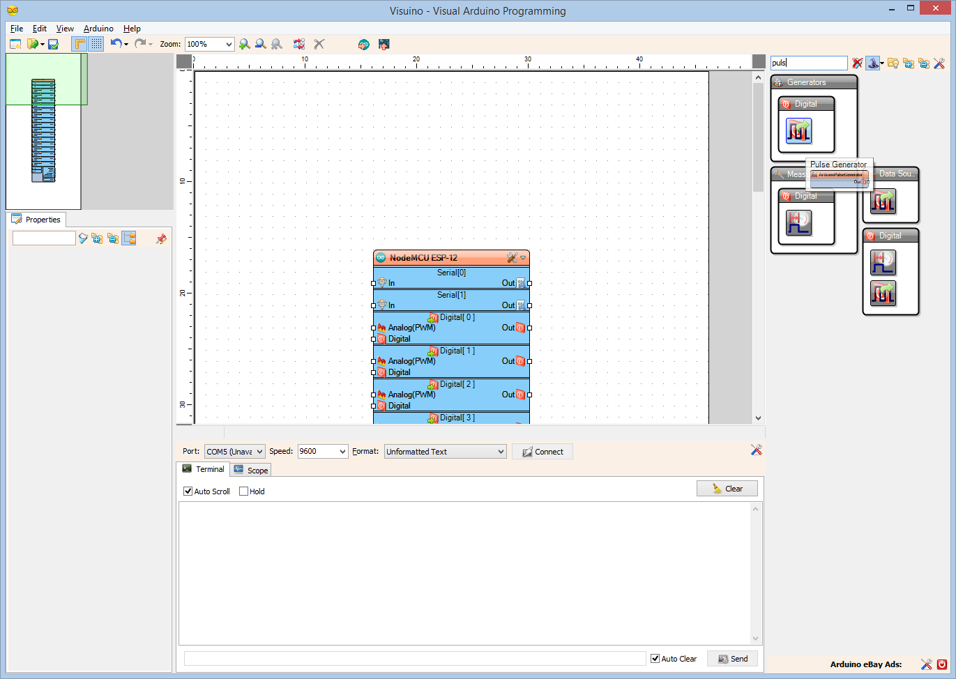
- Type "puls" in the Filter box of the Component Toolbox then select the "Pulse Generator" component (Picture 1), and drop it in the design area
![]()
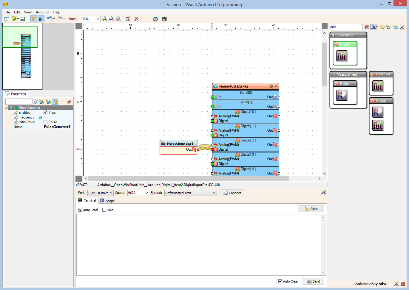
- Connect the "Out" pin of the PulseGenerator1 component to the "Digital" input pin of the "Digital[ 2 ]" channel of the "NodeMCU ESP-12" component (Picture 2)
![]()
- Type "puls" in the Filter box of the Component Toolbox then select the "Pulse Generator" component (Picture 1), and drop it in the design area
-
6Step 6
Generate, Compile, and Upload the ESP8266 code
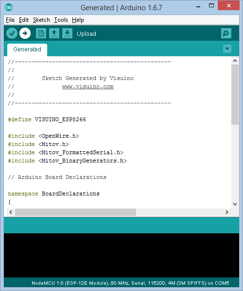
- In Visuino, Press F9 or click on the button shown on Picture 1 to generate the Arduino code, and open the Arduino IDE
![]()
- Select the ESP8266 board type, and serial port as described in this tutorial
- In the Arduino IDE, click on the Upload button, to compile and upload the code (Picture 2)
![]()
- In Visuino, Press F9 or click on the button shown on Picture 1 to generate the Arduino code, and open the Arduino IDE
-
7Step 7
And play...
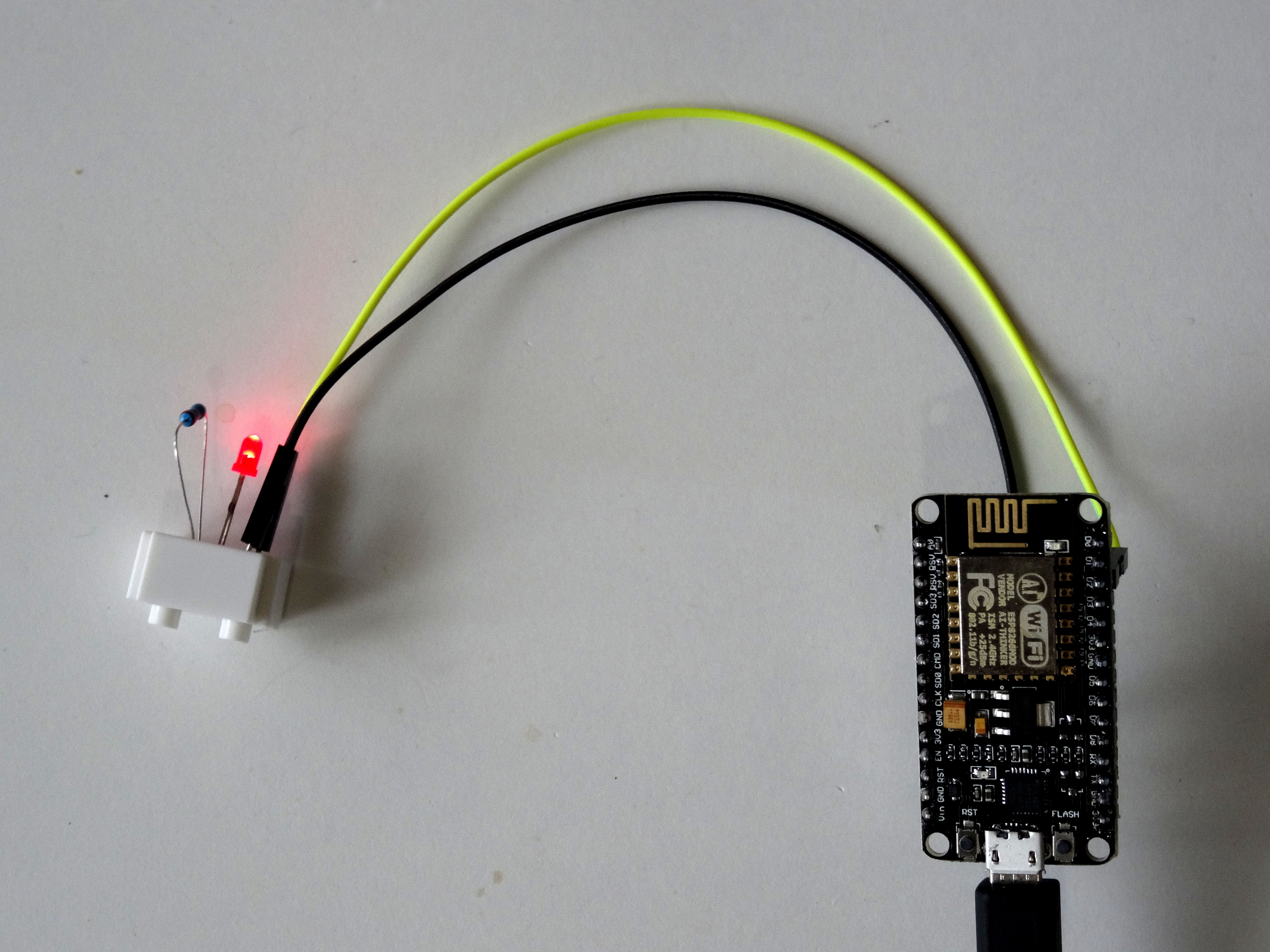
If you power the ESP8266 module, the LED will start blinking once a second as shown on Picture 1 and 2, and on the video.
![]()
![]()
Congratulations! You have completed your first ESP8266 project with Visuino.
Also attached is the Visuino project, that I created for this Instructable. You can download and open it in Visuino: https://www.visuino.com
Blink with ESP8266 and Visuino
Program ESP2866 with Visuino to flash a LED
 Components
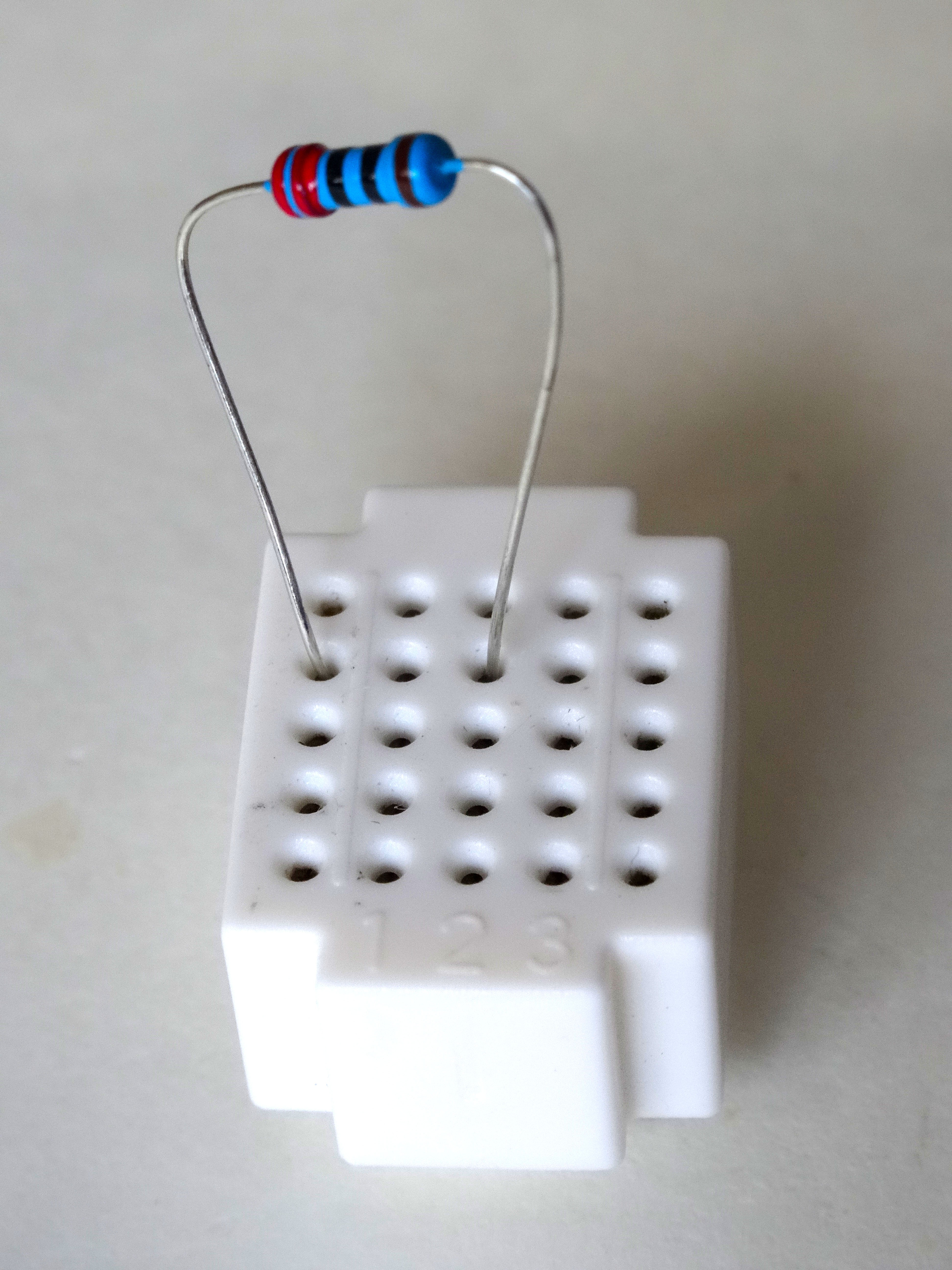


Discussions
Become a Hackaday.io Member
Create an account to leave a comment. Already have an account? Log In.