Close
0%
0%

NeoGeo pi3

A modified Neo-Geo Pocket with a raspberry pi 3 and other clever hacks as its guts.

Similar projects worth following
I always wanted a portable Raspberry pi gaming console, but the most common ones you may find on Youtube would not do the trick for me because of their form factor. In other words, the Gameboy (any version, except for the GBA) will never be the a comfortable option if you want to play awesome third-gen games! like the N64, PS1 or even Dreamcast games which require trigger buttons! ...then I thought "what else can I use?", and the answer was very simple, I had to mod a NeoGeo Pocket!
I had time to think about this, since I couldn't get a Rpi3 in hands, because they are too expensive in my Country. and with all that time I came up with some clever ideas that anyone would love to have in their hands. I'm currently waiting for all the components to arrive and probably next week all the fun will begin!.

The components for this project are following:x1 NeoGeo Pocket.

  • x1 NeoGeo Pocket
  • x1 Raspberry Pi 3 or Rpi2 (less power consumption but less performance).
  • x1 2.4 PiTFT from adafruit
  • x1 Teensy 3.2.
  • x1 blackberry trackball breakout board from SparkFun or Icstation (which is a lot more affordable and has almost no difference. I'll explain this later).
  • x1 powerboost 1000c, there are other option that are better for the pi3 but sadly, I bought this without knowing at the time. I'll share the alternatives later.
  • an stereo audio amp from Adafruit or a mono one. I got the mono since it was obviously cheaper; around 3 US dlls compared to 9dlls (I'm on a tight budget!)
  • x10 Domed tactile switches by C&K components https://www.arrow.com/en/products/ksj0m21180shlft/ck-components
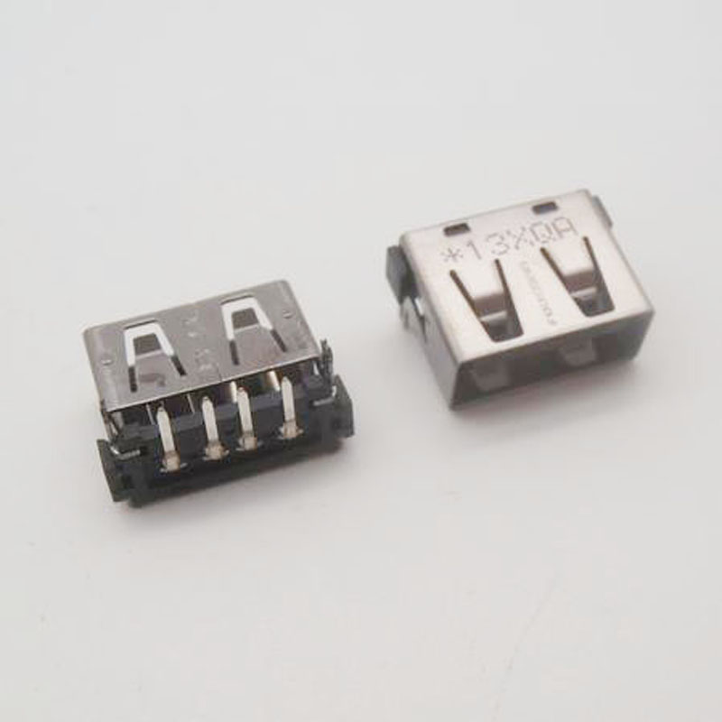
  • x4 "short" USB ports, I got mine from an old and broken Toshiba Satellite A15 laptop. short ones are important because space is critical here!!!.
  • x2 generic cellphone loud speakers (quite tiny as well but they output clear sound at a nice volume thanks to the amp).
  • x2 cellphone vibrator motor (the smallest you can find)
  • wires
  • The hard part is to find the proper Li-Polymer battery, one that fits and has enough juice to power the device for 3-4 hours minimum. But we'll get to it :) I'll show some alternatives to properly power the Rpi3 specifically.

13886321_10154337656084378_6612948944913842418_n.jpg

JPEG Image - 46.75 kB - 07/30/2016 at 07:58

Preview

13782140_10154337690099378_1727660053845596123_n.jpg

JPEG Image - 70.14 kB - 07/30/2016 at 07:58

Preview

13645105_10154337690094378_1030115755555699087_n.jpg

JPEG Image - 64.57 kB - 07/30/2016 at 07:58

Preview

NeoGeoPi3.png

Basically, this is how I want the device to look at the end of this project. The image was originally created by the Deviantart user Blueamnesiac and it is part of his gaming handheld Pixel art. I only added some extra buttons, relocated and modified some dimensions of its elements. like screen size and what not.

Portable Network Graphics (PNG) - 1.16 MB - 07/19/2016 at 02:40

Preview

3outof4.png

I'm pretty much learning how to use the PCB software. so far I've noticed that with it, you can't create traces that look as artistic or somewhat abstract as I want them too look. so I guess I'll end up finishing the PCB with KRITA which is an open source Image editing program similar to Ps. why? well, at this point I'm simply going to make a file for manual PBC etching that I can print in transfer paper, rather then an actual .pcb file I can send to some manufacturer. In the future I will totally want to create a more professional version that can by printed by someone else in bigger quantities.

Portable Network Graphics (PNG) - 162.09 kB - 07/19/2016 at 02:28

Preview

  • It lives!! (Sort of)

    Kevin Osuna11/03/2016 at 12:25 0 comments

    Well, it is time for an update, I assume this will be a long one (since I've been away for a while) in which I will try to explain everything that's happened lately in relation to the NeoGeo Pi 3.

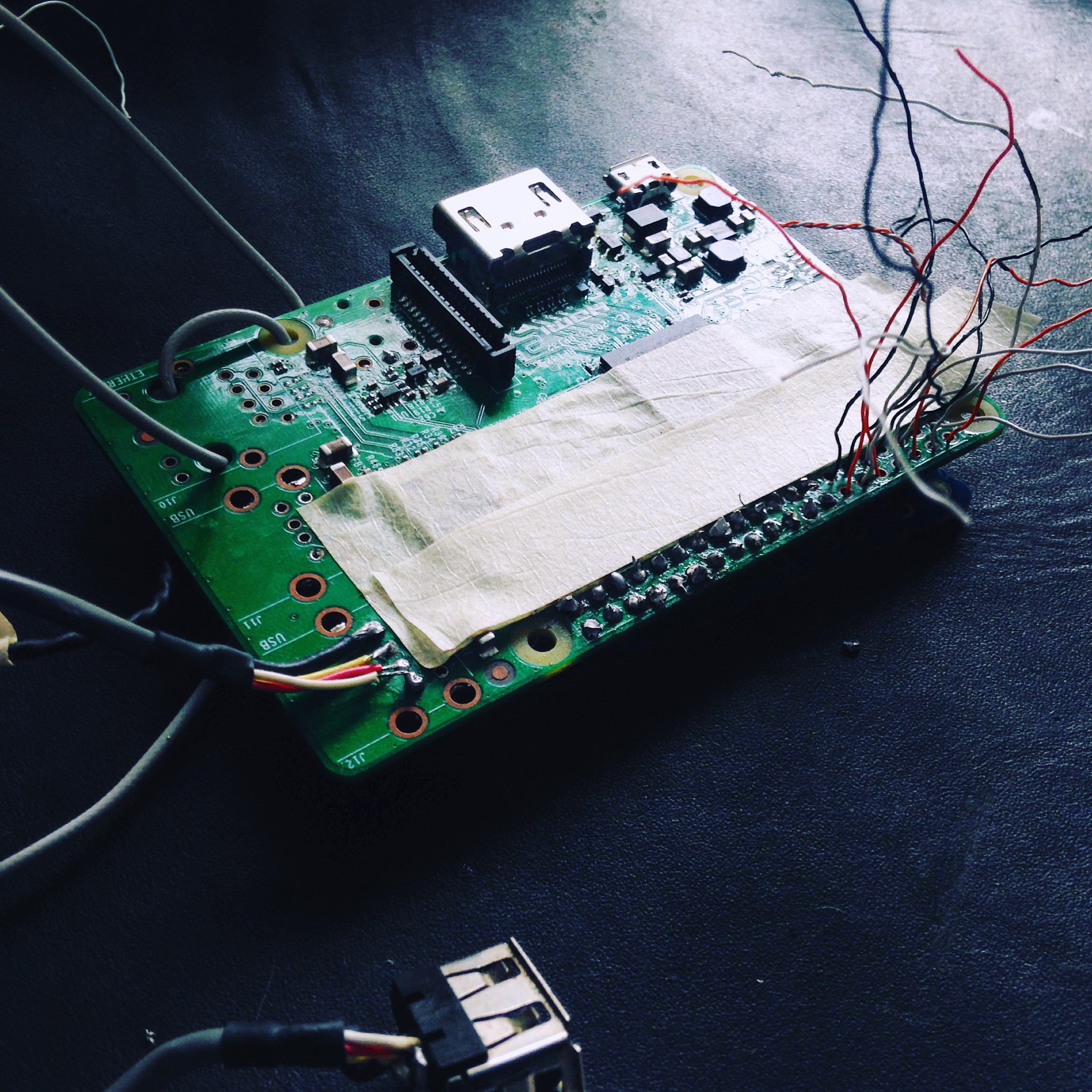
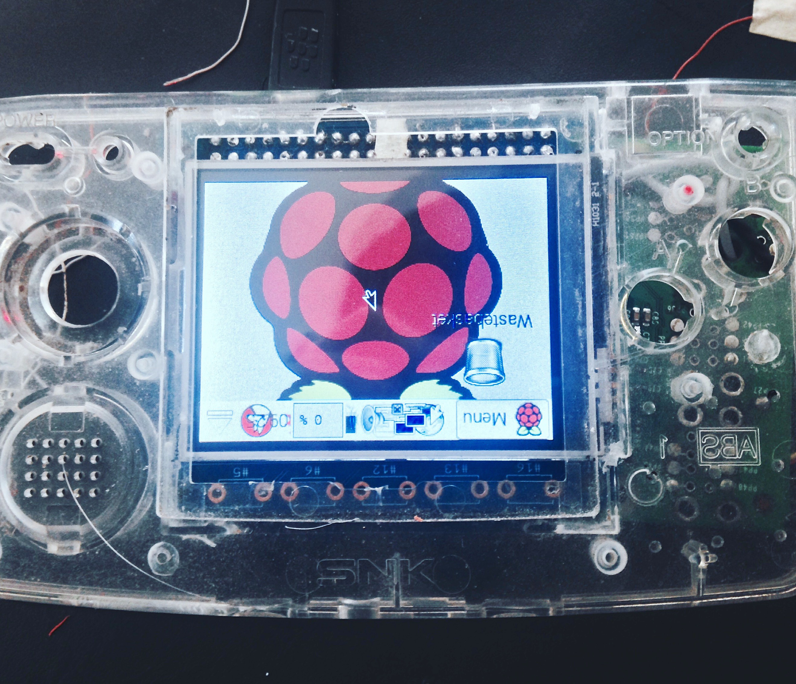
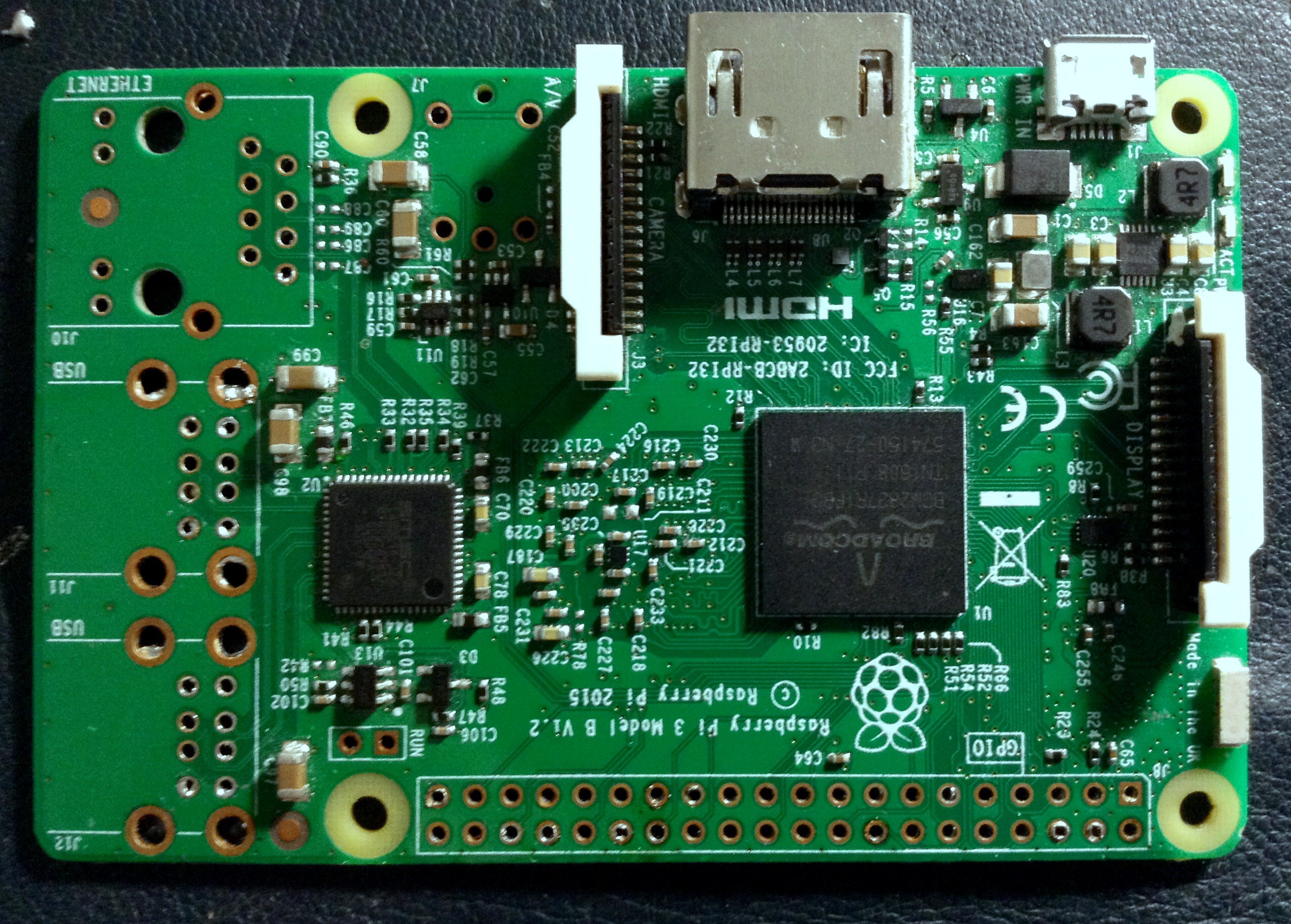
    Let's get started! After desoldering the Ethernet, audio/comp video and USB ports I began gathering the ISO images I wanted to test the Raspberry Pi 3 with and had success booting them up to a certain extent, what do I mean by that? Well, only one if them completely booted up, I'm talking about OSMC, while the rest got stuck while mounting /boot or something I can't recall. I had a theory, the two images that didn't work were meant to be used specifically with the PiTFT and I certainly had not solder the display to the Rpi yet. So I figured that could have been the reason.

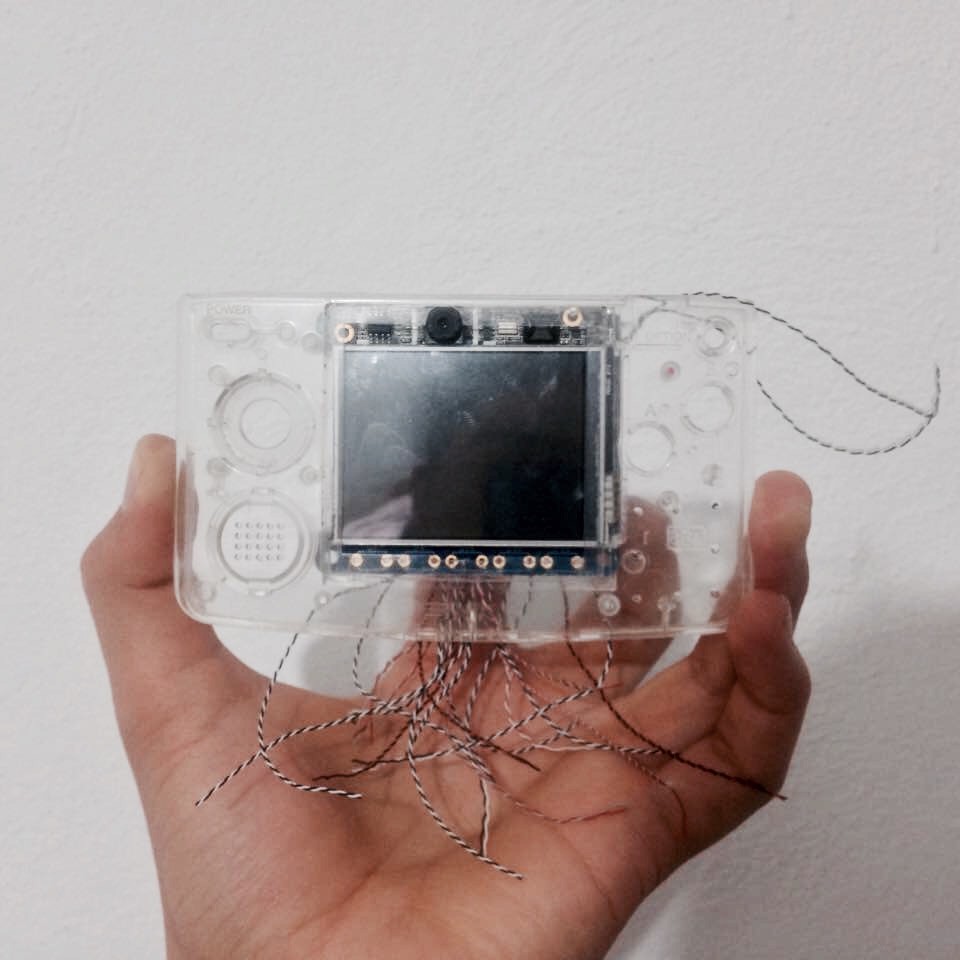
    There was only one way to find out out so I had to get the time to solder the display in place, yesterday I finally had the time and patience for such hassle and it wasn't easy because in order to save space I ditched both, male and female headers and instead I got some really thin wires from a broken laptop's screen and had to cut them to the right size, tin them and finally make sure I was soldering them to the right spots. I'm talking about 40 tiny and fragile wires that could have been shorted out from the beginning, even before I knew about them (I have no voltmeter so I took a chance).

    in the picture below, you can see some really dirty solder work, but believe me nothing bridges here, I made sure of that.

    But at the end everything worked. At least I think so. I couldn't get the touch-screen to work since I have no usb keyboard to configure it, which brings me to another problem: I plugged an USB mouse to the only usb port I have installed and there was no response. The Rpi3 doesn't seem to detect anything and the mouse seems to bee receiving zero power from the PI which really worries me.

    Did the USB controller chip die while I de-soldered the ports? I really hope it did not, because I doubt there's a way to fix that or a way around it. So tomorrow I will test the other ports with different wires to see what's up.

    In case it doesn’t work, this project will have to wait until I can get a new Pi. like I mention in a previews log this things aren't cheap here in Mexico so I gotta find a way to buy it in the USA and get it shipped to me by a friend during holidays. I am so excited about this project more than ever now that I see that tiny screen shine as bright as it does! so wish luck if you are seeing this.

    The next step will be to configure the touch-screen and obviously rotate the screen in the .config files (?) I don't know...I have time to figure that out {update: there is console helper (sudo adafruit-pitft-helper -t 28r ) besides there's a long tutorial on adafruit's website: Right here

    If the USB ports don't make it, then, while I find a way to replace Rpi, I'll keep working on the rest of the project; the case mod and programming the teensy to work the way I want it to. Cheers! and thanks for following if you are!

  • A Somewhat Slim Raspberry

    Kevin Osuna09/12/2016 at 19:39 0 comments

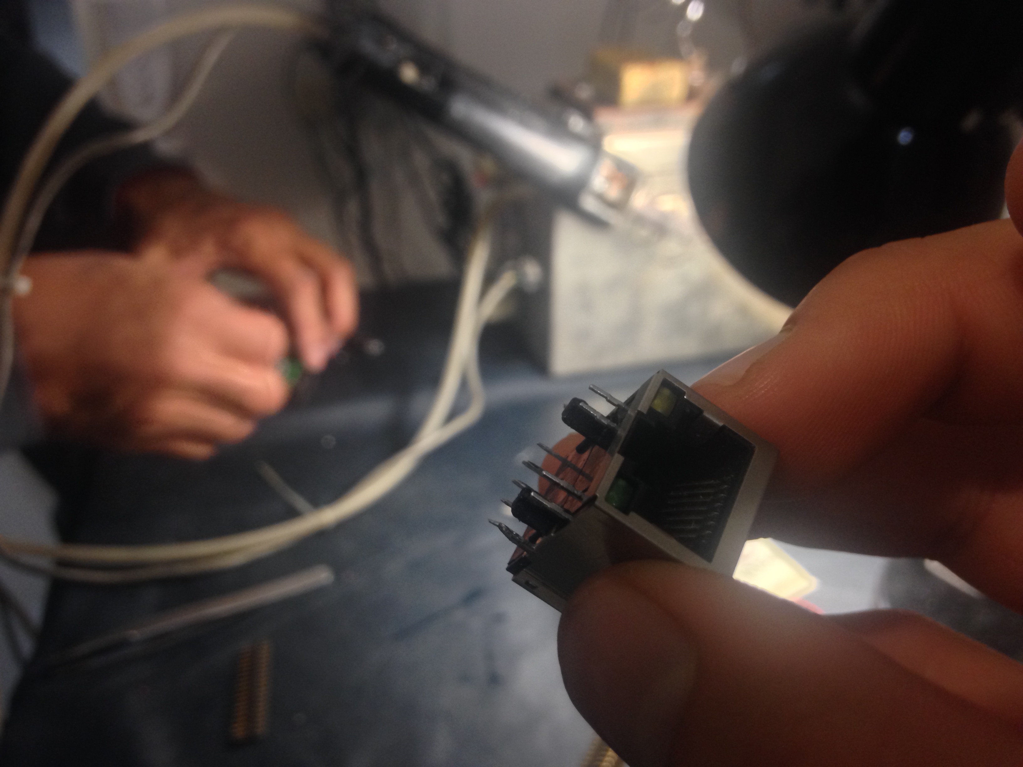
    One of the biggest difficulties I've experienced so far while working on this project, has been the hardware hack which is needed in order to remove some of the ports from the "Pi3". I have some experience soldering very tiny wires to almost unreachable places, but desoldering was completely new to me. I had a good idea of how I was supposed to remove the header and when the time do so came, It turned out to be quite easy, a long and boring easy process with some hiccups along the way. When the time for desoldering the Ethernet and USB ports came, that's when I felt totally lost. The only tools I had were a cheap soldering iron and some desoldering wick, when I realized these tool were not enough, I bought a manual desoldering pump, thinking it would easily get the job done but apparently the problem ware'nt the "cheap tools" I had but the instead, the problem was my lack of knowledge and skill I needed to achieve a result as clean as this:

    Luckily, I knew the person who could, effortlessly, get the job done in a matter of minutes. I'm talking about my uncle Adan. He's a very experienced electrical engineer who has been messing with electronics for most of his life. In the following video you can see him using his custome built desoldering iron/pump. Hope you enjoy watching the video as much as I did in person.

    As you can see, the ports came out very clean, he did a very professional job indeed and I'm very happy he had the time to help me with it. Now I can finally move on to the next step of this project

  • Adding the Camera

    Kevin Osuna09/05/2016 at 23:18 0 comments

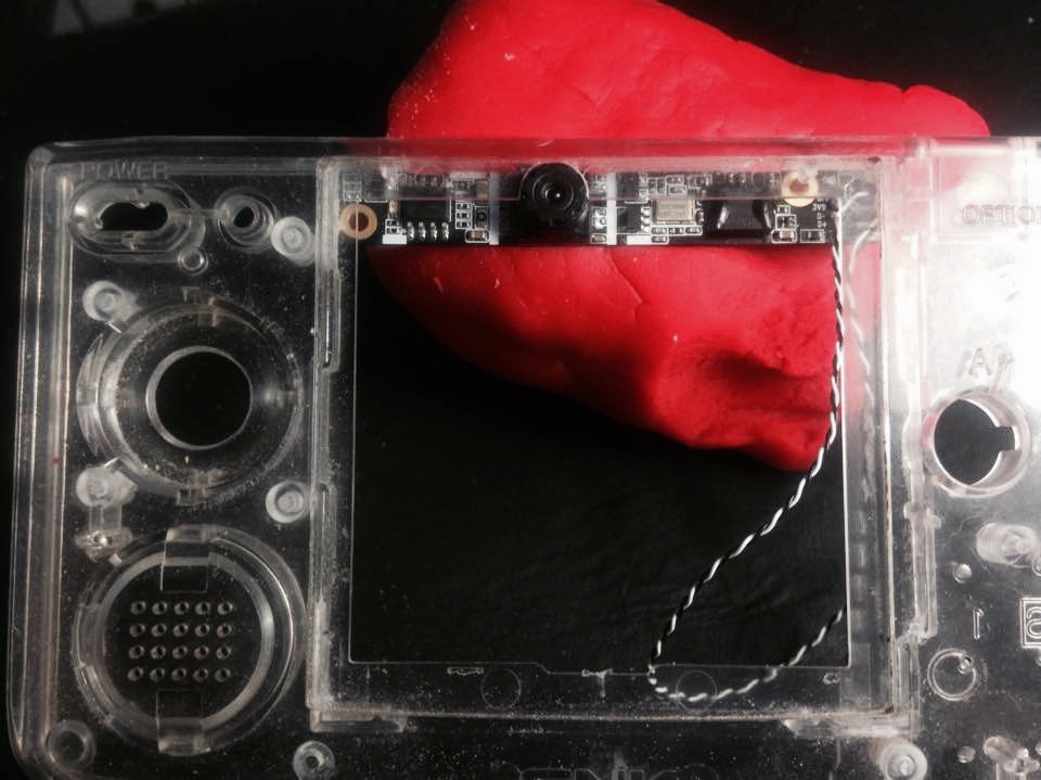
    After carefully measuring the camera module, the place where it will seat and the components that lay on top and right next to it, I've decided that it is not only possible but necessary to add this camera. I may be stretching the word necessary a little here... I mean, we could live without it, the thing is that when you find something that fits so well inside of a project like this, you just have to take the risk and see how it turns out. This are the kind of events which make projects like this so fun to work on.

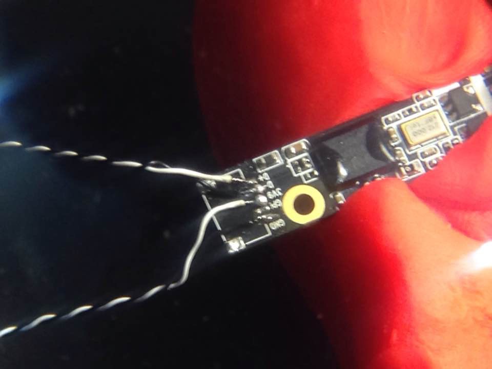
    In order to fit the camera module without too many extra modifications to the case, I simply had to remove the white connector and solder wires directly into the terminals. This wasn't as hard as expected.

    Then I carefully added some hot glue to secure the wires I had just soldered, at the end it looked very clean. After that, using the engraving tool, I made a hole through which the camera lense could go. I had to be very precise on how far I had to dig, I wanted it to be the perfectly sized and shaped. That way, there would be no need for glue on that part, after all, this is a very visible part but even if a had made a mistake, that can be covered with a custom, acrylic faceplate.
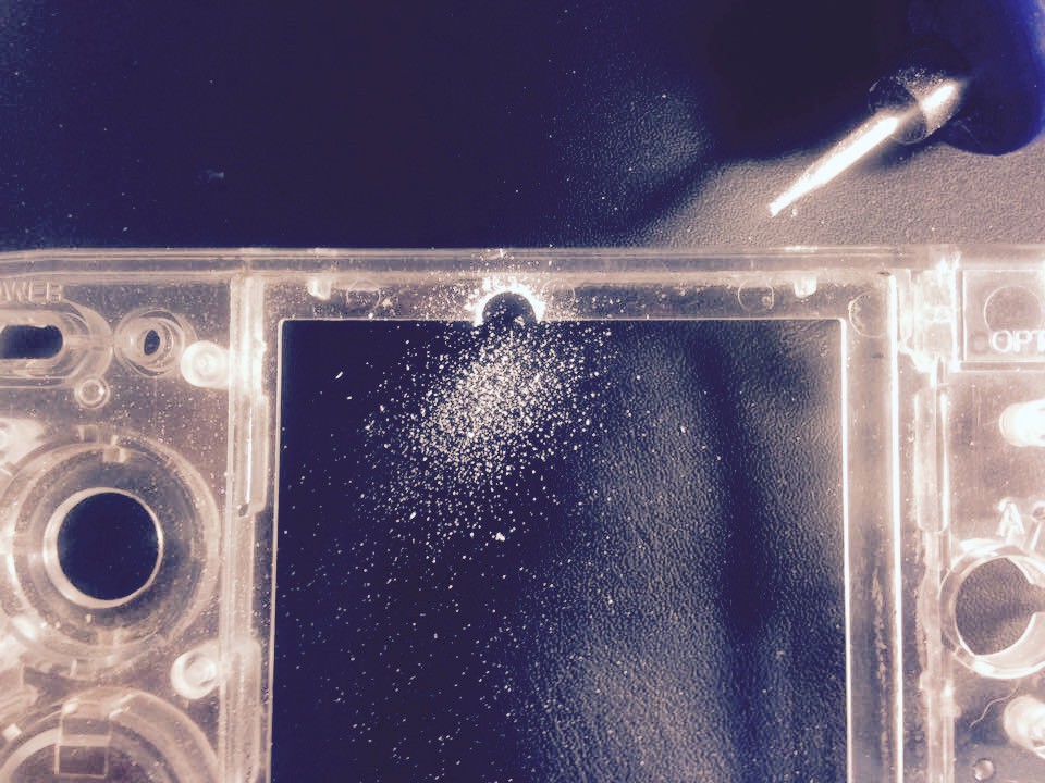
    The hole had to reach the edge of the "front bezel" (let's call it that way) without damaging it. I'm referring to the part in which the faceplate seats. As you can see in the picture, I still had a long way to go.

    Now, in the picture below, you can see how everything fits quite well after it is assembled:

    Please leave a comment or question, your feedback is of big interest to me. that's all for today! Thanks a lot
  • Face button clone (how to)

    Kevin Osuna08/27/2016 at 23:03 0 comments

    I'm trying to add this log using an stupid IPad and let me tell you what ...it really sucks!

    Anyway, I was trying to explain how to duplicate the face buttons using household materials mainly, but there was an error in the page and it reloads itself without asking!!! So I will try to do my best with the little patience I still have. My laptop died two days ago during a thunderstorm while I was out, I would normally avoid using an IPad at all costs but this is all I can do for now.

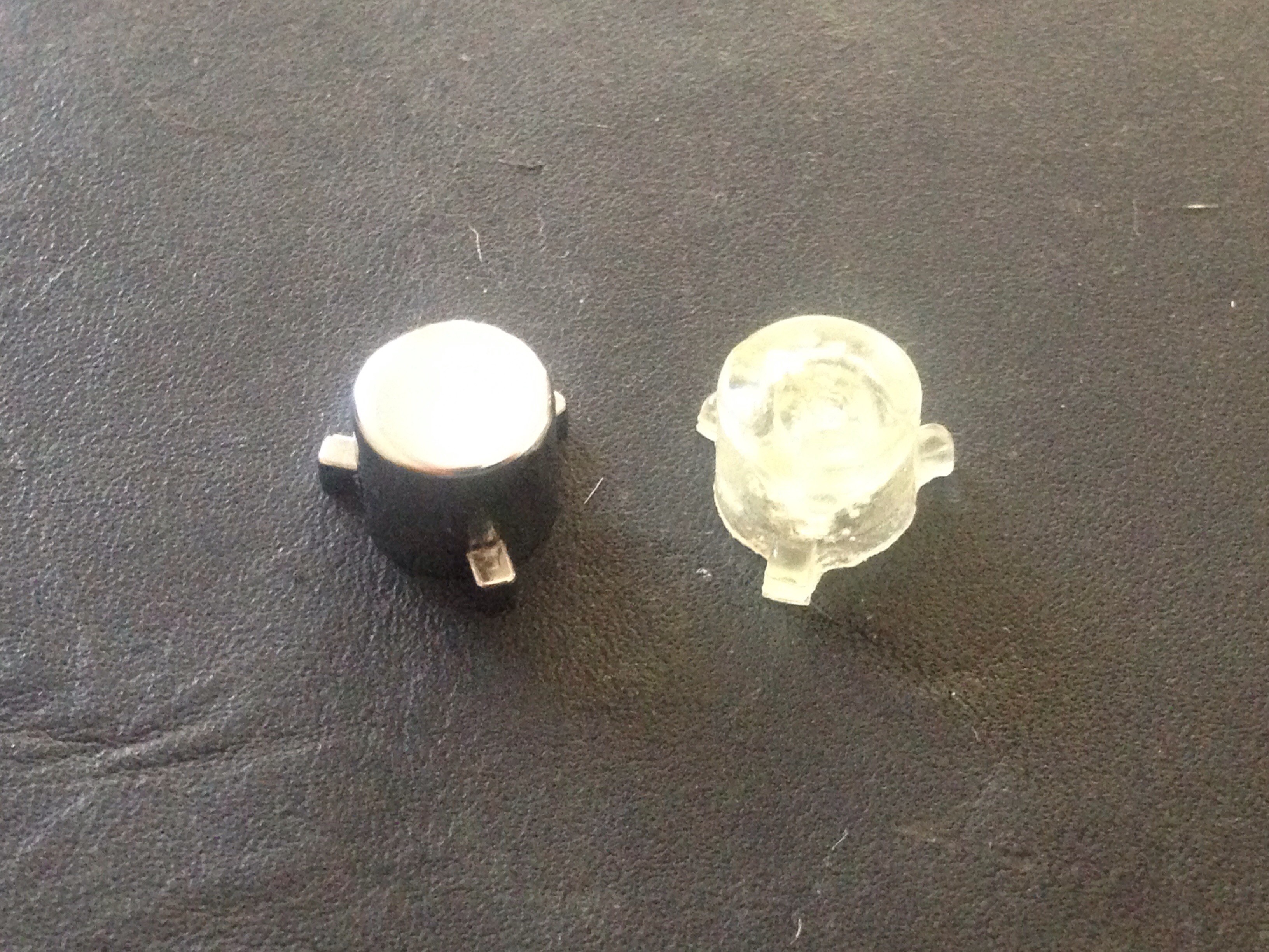
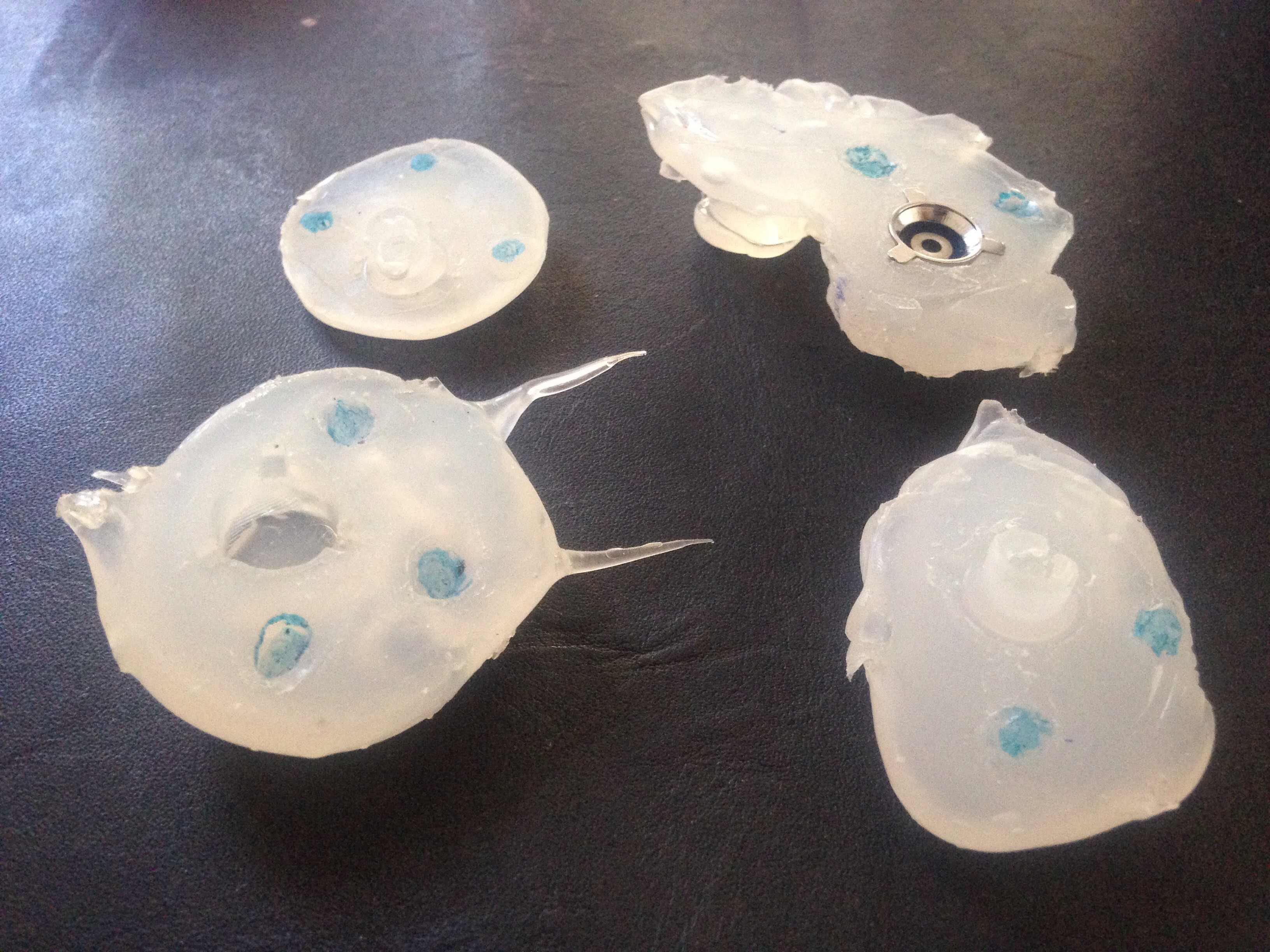
    So, here's a picture of the finished button next to the original one:

    The image quality may not be the best, but in person it looks and behaves excellent. It was made with epoxy, that's why it has lots of bubbles in it, which is not a big problem since they are inside and not in the surface of the button. I plan to paint the buttons in order to make them look identical to the original ones.

    These are materials you will need if you want to attempt the same:

    • Hot glue gun + silicon (duh)
    • A small sheet of glass
    • "PAM" anti-adherent
    • A lot of patience

    Basically, you'll be making a two part mold just like any other. You can find hundreds of video tutorials on YouTube.

    I particularly got the idea after watching a video from Tested's channel in which they try to explain how to make props for movies, like rubber hammers, knives and even a light saber, maybe that was a separate video (we'll never know).

    The main difference here is the materials and the size of the project. This difference has it's pros and cons. The low price being one of the pros, while the difficulty of and short working time of the hot glue and epoxy are on the negative side.

    On the next pucture you can see my molds:

    I made two sets of molds the first one didn't convince me (left one) so I tried a second time (right side) and that one came out pretty much perfect.

    Basic Instructions:

    1. Spray the original button and the small glass sheet with "PAM" making sure you cover the button completely.
    2. Place the button on the center of the glass with the top of the button facing up. Keep a needle near you, you may need it to get rid of bubbles.
    3. Take a deep breath and start covering the button with silicone, start from the side, going around it while pressing the button against the glass sheet. It's important that you press it the whole time, otherwise, it will lift up an the silicone will get under it. The inner part of this first half of the mold needs to be completely flush with the bottom of the button.
    4. You can use the needle to move the bubbles away from the surface of the button while it is hot. Or you can keep "shooting" silicone at the part with the bubbles and they should move away.
    5. If you feel everything is right then you can let it cool down and once it is at room temperature you can carefully remove it from the glass.
    6. Examine everything and if it is okay m, then move on to step 7.
    7. Spray it once more with the anti-adherent making sure that the oil reaches even the small holes on the back of the button.
    8. You can remove the button from the mold to examine it but must put it back in place to make the second half of the mold.
    9. Put it back together and place it on top of the glass. Put everythin inside of a topper and make it spend around 5 minutes in the freezer.
    10. Take it out and remove it from the glass sheet. Use an xacto knife to make some holes on the bottom that will serve as registration mark so that both halves of the mold fit in place prgectly every time. Rub your finger over the bottom part to make sure it still is greasy, if not, add some more oil with your finger. The first half needs to be cold so that it doesnt deforms with the heat of the second half you will be adding.
    11. Add the second half, making sure that the silicone reaches the deepest part of the inside of the button and that there's no bubbles.
    12. Let it cool down completely and separate the two halves.
    13. Prepare the epoxy and put it inside a suringe without the needle.
    14. Carefully, inject the epoxy into the first half until it reaches the surface.
    15. Add the second...
    Read more »

  • webcam or no webcam?

    Kevin Osuna08/17/2016 at 18:37 0 comments

    So, I've been playing around with different ideas for possible addition I could make to this thing, and well, there's a couple that interest me more then others. This is one of them...

    I am basically an electronics scavenger, have always been one. I recently tore down a couple of old and broken laptops from which I am taking different components; all kinds of ports, wires, copper, screws and those metal screw-hole inserts that you can find on any device with a plastic construction.

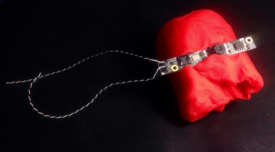
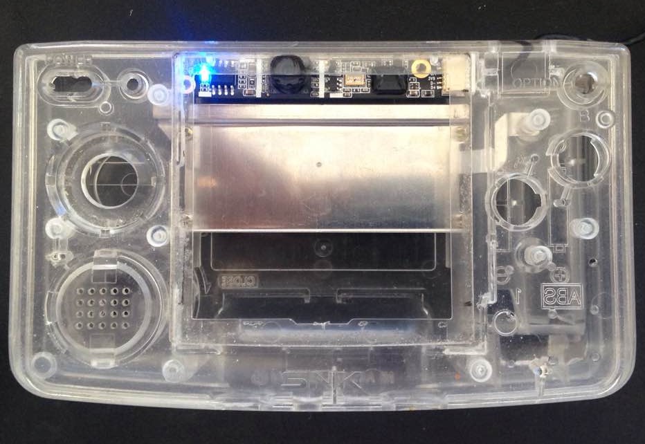
    A couple of weeks ago I took a Camera Module from one of these laptops but I couldn't really see any use for it. Until I saw some labels right next to the white connector. These labels detail the pin-out of the module itself and realized that there's no difference on this thing from any regular USB Device. I mean, this has a Ground, Power, D+ & D- and it was so obvious what I had to do with it, I had to turn it into an USB Webcam and see if it could fit inside the Neogeo pocket.

    Apparently, it does fit. but for that I need to put the display a little lower than how I had previously planned, I'm talking just a couple of millimetres, nothing too scary. I'm not sure how many mega-pixels this camera has but the image quality it great, at least for video calls and stupid selfies.

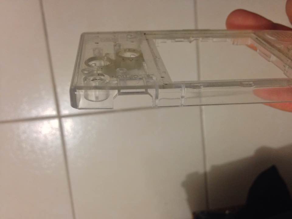
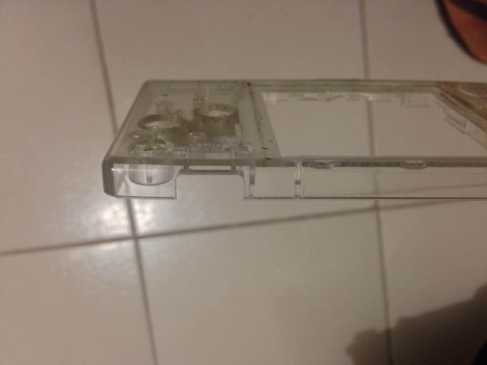
    in this picture you can see the original shape the port-hole (that sounds funny) has. in order for the USB port to fit, I must modify it a little with the engraving tool I'm using.

    here it is already modified:

    And here it is with the port in place (more less):
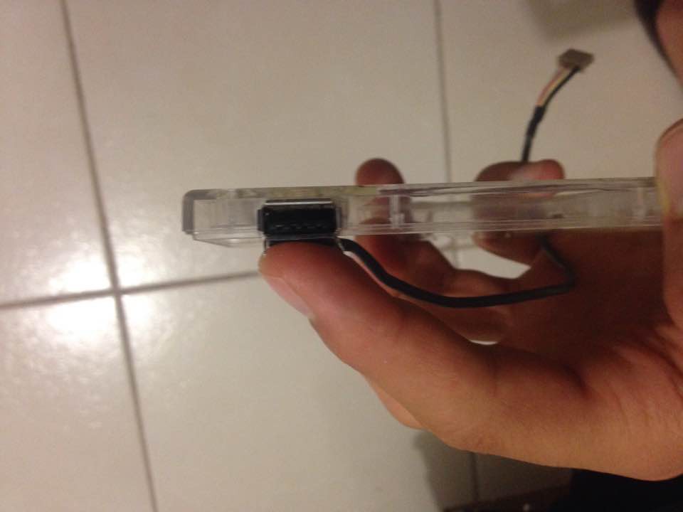
    I'll be using a different cable for the USB, this one's too thick.
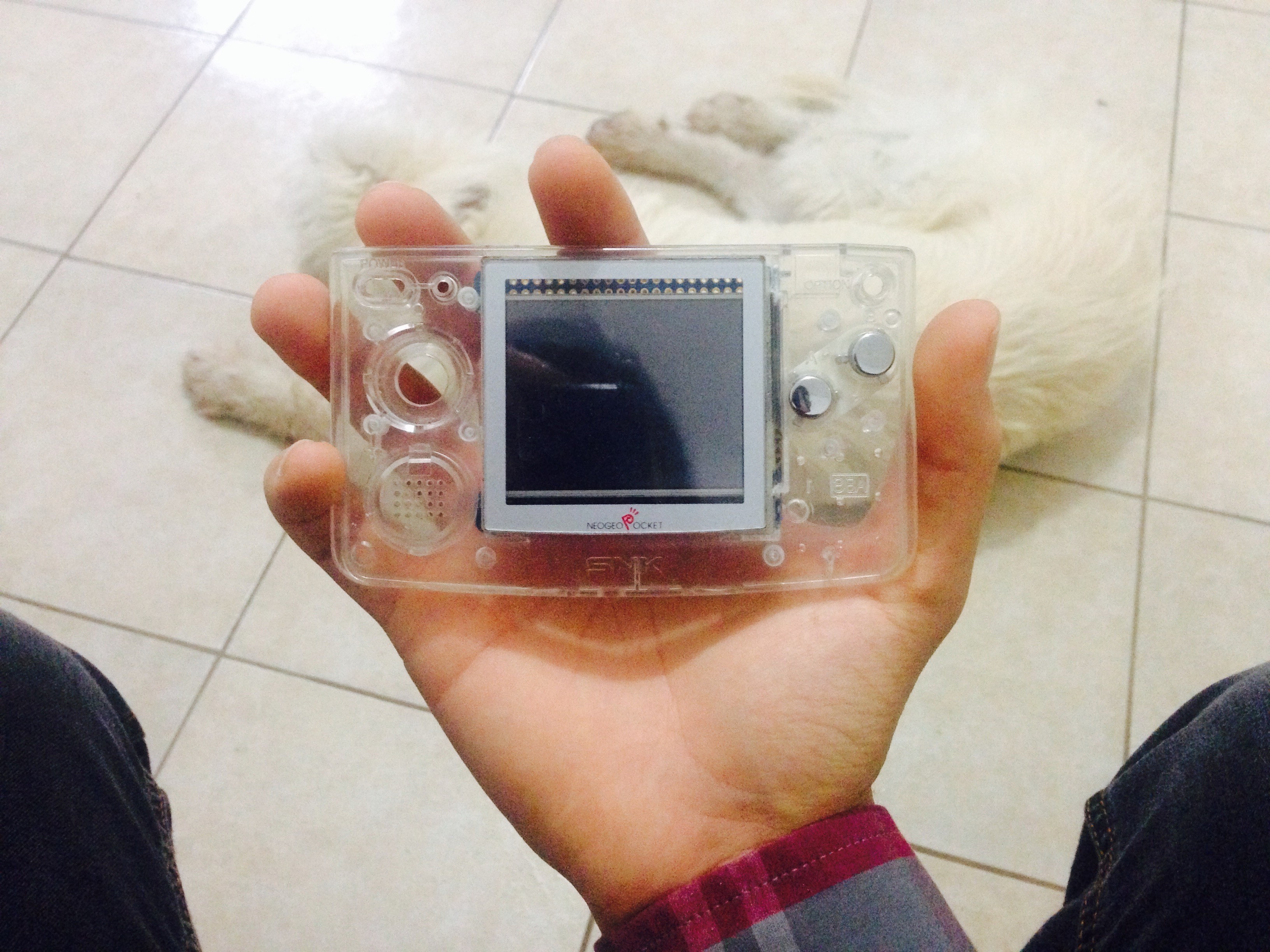
    After this, I'll start working on the holes for all the other stuff like buttons, trackball and another one for the camera. By the way, this will have a little camera bump, a little more then a millimetre ... If high-end Smart-phones are allowed to have them why not this thing.

    I'm sorry for the slow updates, I've been super busy lately, We have a tiny pizza restaurant and It is so time consuming.

  • Perfect fit, so far!

    Kevin Osuna08/06/2016 at 10:25 0 comments

    Hey there! I've had a pretty busy week! but I'm still trying to progress quickly and share constant updates on the NeoGeo Pi3.


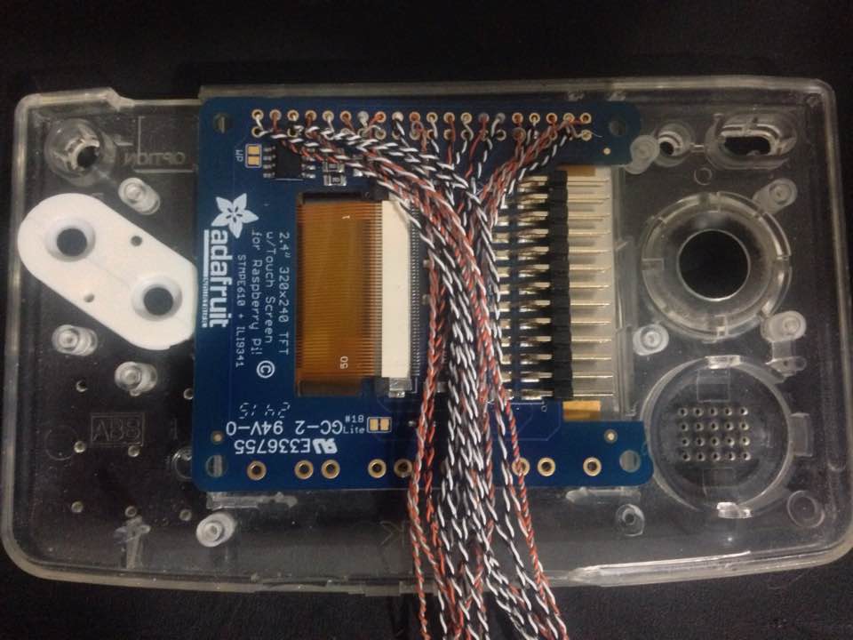
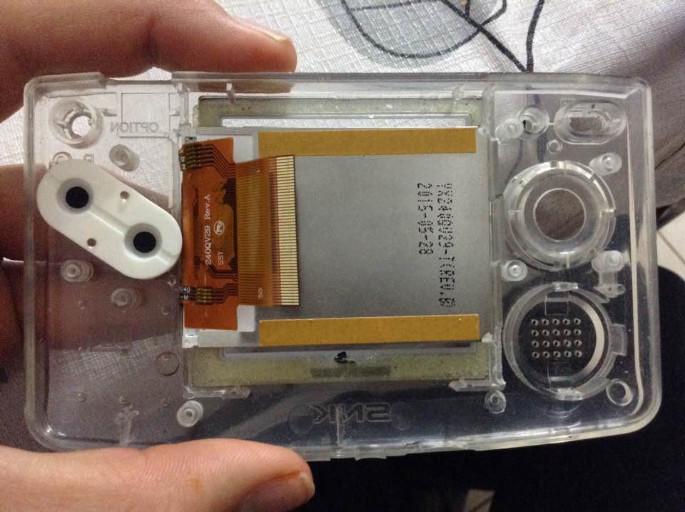
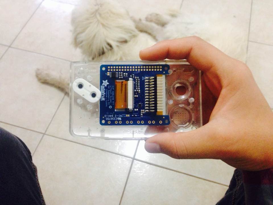
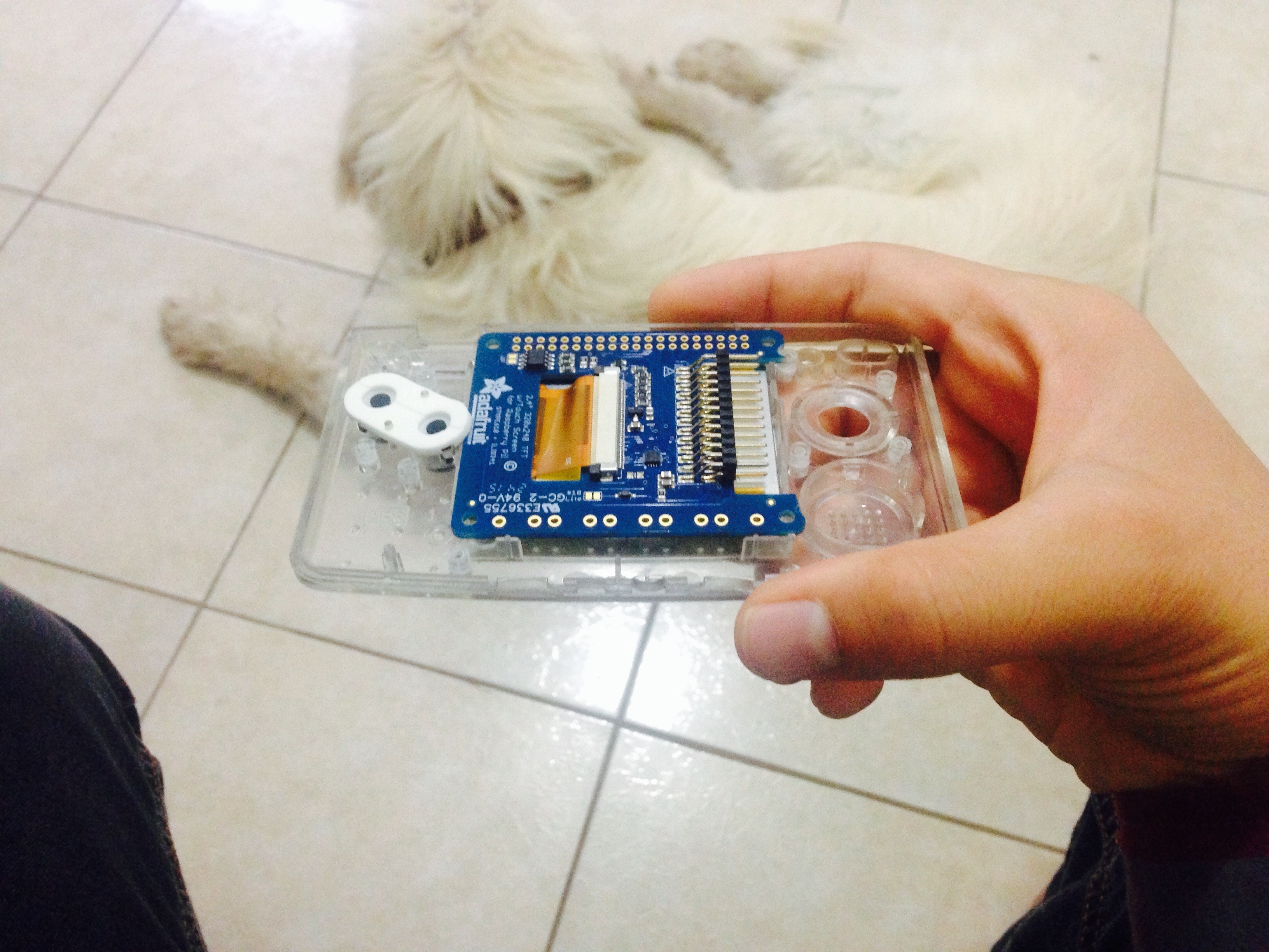
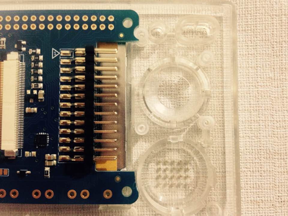
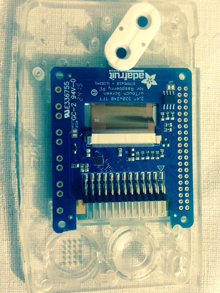
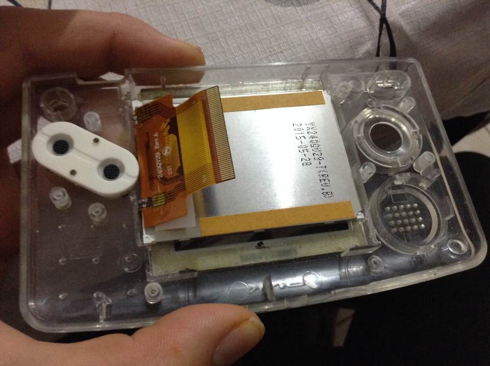
    This week I was able to place the PiTFT 2.4" display in the right place. I decided to put it up side down for a pair of reasons; the main one being that I want to have the tactile switches on the bottom of the screen instead of having them on the top. Putting all the aesthetic reasons aside, that way I can use the space on top for wires that will connect the "new" USB ports to the Raspberry pi3. the second reason is that there's a bezel which used to hold the original display in place, and it has some extra space in one of the sides which is perfect for the screen's flex cable. By giving the flex cable that little extra space we prevent any possible damages that could come from other component applying pressure to the flex cable.


    In the second and third picture you can see how the flex cable is having a hard time trying to fit in there. Well, that's because the part of the PCB where the header goes still needs to go lower. for that I need to sand the bezel a little more


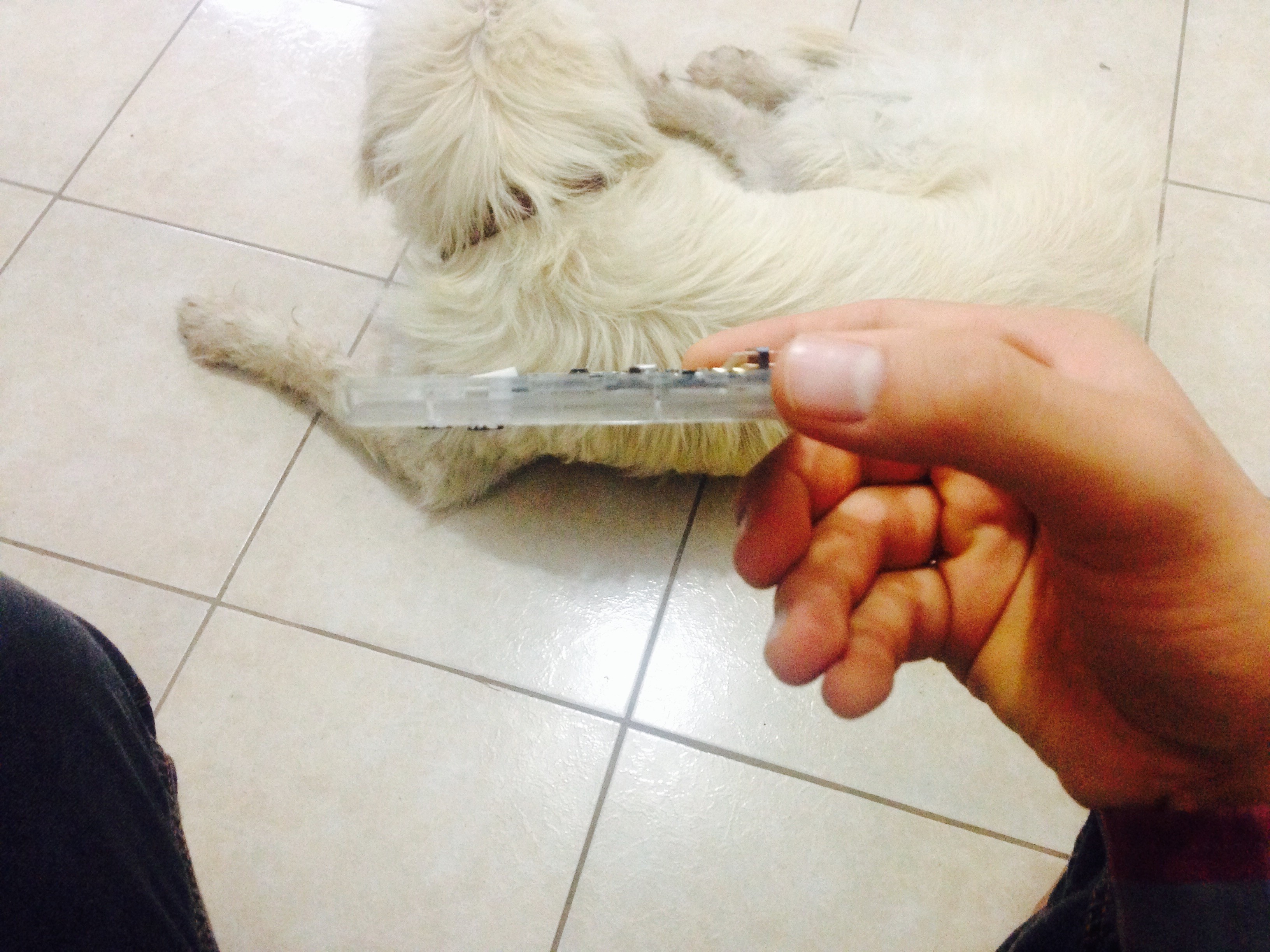
    in this picture you can see how the display and the PCB fit pretty well inside the upper half of the case, and I still can dig a little more into the bezel to get the two components (display & PCB) touching each other. Right now there's a space of a little more than a millimeter between them.

    One of the reasons it fits quite well is that I was able to sand of some parts of not only the case but also the PCB without even getting close to any trace and ruin it. I used a cheap engraving tool I found at home. it took from 10 to 15 minutes because that tool isn't very powerful. But that was a good thing, that allowed me to go easy on it and not screw things up.

    So I guess this isn't bad for the first modification I make for this project, everything seems, fits and feels like it is meant to be. I'll keep you updated.
    By the way, if anyone has experience with programming the Teensy 3.2 I would really appreciate all the help you can give. that would speed things considerably.

    The combination of functionality I'm aiming to is keyboard+mouse and if there's enough space and if it's possible to implement I could even add a scroll wheel to one of the trigger buttons. It's an idea I have always wanted to try. Some months ago I read that Nintendo might do that with their new NX and I though "where's my money nintendo, where?!!!" But in the mean time if you want to collaborate in any way, please, let me know. Another way you can contribute is by supporting me on patreon. that would allow me to focus a lot more on this project only. https://www.patreon.com/Kev_os

  • They arrived! Let's get stardet!

    Kevin Osuna07/30/2016 at 08:21 0 comments

    It took a while but finally we have all we need, so let's get to work.

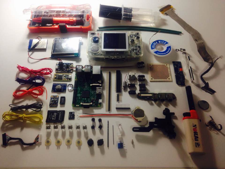
    Here we can see a collection of components like the Rpi3, a tiny PiTFT, the mighty teensy 3.2, a black-berry trackball breakout board, mono amp 2.5watts, some tools and the mighty NeoGeo Pocket. you can also see some things which may not make it to the final cut, but I hope to find a good use for them in this project.

View all 7 project logs

Enjoy this project?

Share

Discussions

TheotherMike wrote 03/28/2017 at 18:39 point

Hey there, something new ?? ;-)

  Are you sure? yes | no

TheotherMike wrote 09/06/2016 at 09:01 point

Nice fit, the Webcam is a perfect match. Does it also have a microphone in it?

  Are you sure? yes | no

Kevin Osuna wrote 09/06/2016 at 17:13 point

It is a perfect match indeed, sadly, it does not come with a microphone in it. 

  Are you sure? yes | no

TheotherMike wrote 09/06/2016 at 17:31 point

Arrghh,....too bad ! Would give a very nice video communicator ;-) But small usb type microphones are not expensive..

  Are you sure? yes | no

Kevin Osuna wrote 09/06/2016 at 17:41 point

I just found this tiny usb mic: https://www.amazon.com/Kinobo-Microphone-Desktop-Recognition-Software/dp/B00IR8R7WQ and like you said, it is not expensive. I might give it a try soon. The camera module has this labeled on the back:    94v-0 ck77.  This is the closest I hace found: http://m.ebay.com/itm/HP-dv6000-dv9000-tx1000-WebCam-Web-Cam-Camera-Board-431392-001-446488-001-/222216848974?nav=SEARCH

  Are you sure? yes | no

TheotherMike wrote 07/31/2016 at 09:32 point

Yeahh, would be great inspiration ! I don´t have a NeoGeo, but I too ordered some parts to play around.... ;-)

  Are you sure? yes | no

Kevin Osuna wrote 08/17/2016 at 18:50 point

Awesome let me know If you need any info of where to get  the components I posted and if you get a teensy and the trackball I would totally appreciate your collaboration with that part . Also, you can totally get a cheap NGP on ebay,  I'll keep an eye on the good deals and let you know. 

  Are you sure? yes | no

TheotherMike wrote 08/18/2016 at 18:48 point

Hey Kevin, very nice from you, thank you ! I will tell you if needed. I think I can get everything, although it will take some time. Analog sticks and buttons already arrived... :-) I think the tft will last much longer.

  Are you sure? yes | no

TheotherMike wrote 07/30/2016 at 09:42 point

Very nice!

Have much fun while building it !! :-)

  Are you sure? yes | no

Kevin Osuna wrote 08/17/2016 at 18:51 point

Thanks! you bet I will :D I'll try to keep sharing constant updates as well

  Are you sure? yes | no

Similar Projects

Does this project spark your interest?

Become a member to follow this project and never miss any updates