DotPiDot
-
Controller Replacement
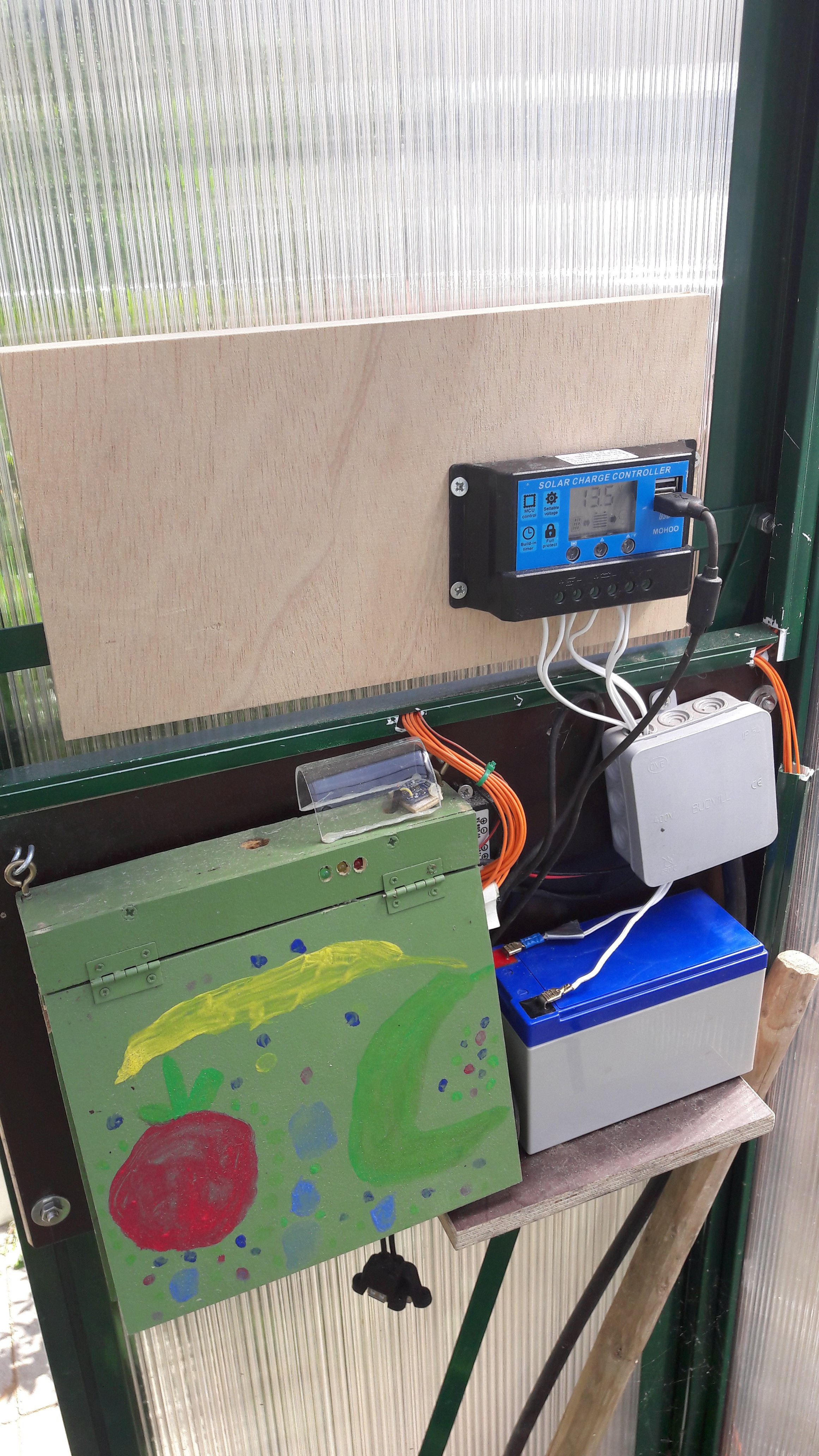
06/20/2017 at 18:41 • 0 commentsStarting this years activities I had to exchange the charging controller as the old one did not have protection against deep discharge. This led to a destroyed battery - so i had to exchange both - battery and controller...
![]()
The new controller now has a nice display and protection against deep charge. The voltage levels (float voltage, load off voltage, load on voltage) are adjustable. I'm missing some details during the charging activities (like consumed w/h, charging energy w/h) which i actually exepected the controller to have. As it looks it does not have these functions - on the other hand it was not a really expensive thing - something like 20€... -
Enabling 1W with Raspberry PI
09/04/2016 at 15:19 • 0 commentsExcecute the following
sudo modprobe wire
sudo modprobe w1-gpio
sudo modprobe w1-therm
change the modules file by calling:sudo nano /etc/modules
and add the following lines at the end of the file:wire w1-gpio w1-therm
if you use kernel 3.8 or higher then additionally execute:sudo vi /boot/config.txtand add the following lines
# Temperatursensor an 1-Wire
dtoverlay=w1-gpio
gpiopin=4
then trigger a reboot :sudo rebootto check whether it worked fine excutesudo lsmodwhich will give you some results similar to thins:
Module                  Size  Used by
i2c_dev                 6386  0
snd_bcm2835            22502  0
snd_pcm                92861  1 snd_bcm2835
snd_seq                58152  0
snd_seq_device          5142  1 snd_seq
snd_timer              22156  2 snd_pcm,snd_seq
snd                    67534  5 snd_bcm2835,snd_timer,snd_pcm,snd_seq,snd_seq_device
8192cu                556175  0
i2c_bcm2708             5988  0
w1_therm                4347  0
bcm2835_gpiomem         3703  2
bcm2835_rng             2207  0
w1_gpio                 4295  0
wire                   30987  2 w1_gpio,w1_therm
cn                      5756  1 wire
uio_pdrv_genirq         3526  0
uio                    10078  1 uio_pdrv_genirq
Important is that the three moduleswirte, w1_therm and w1_gpio are included in the lsit now...
-
Software Part II - Adapter Framework
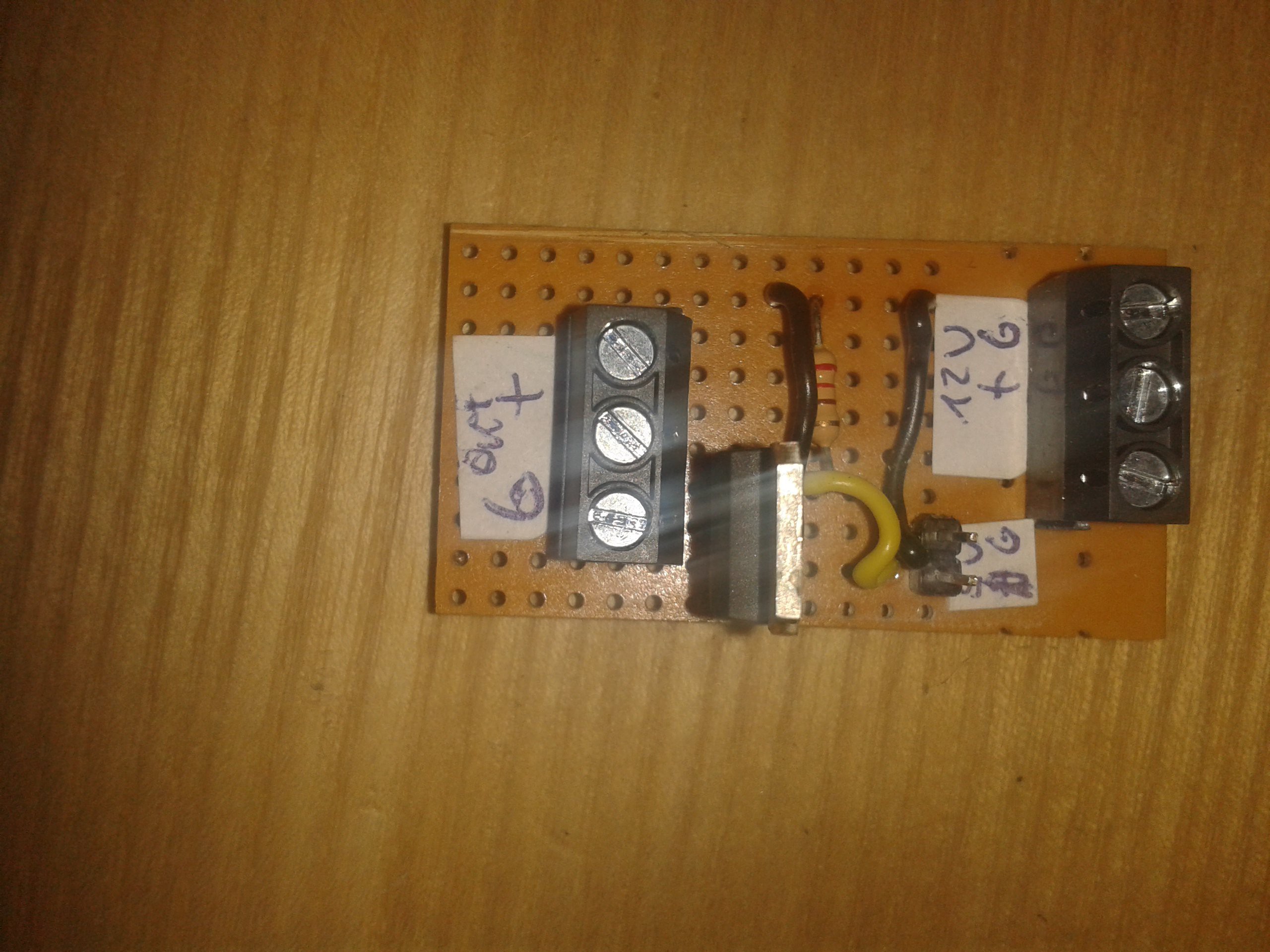
09/04/2016 at 11:17 • 0 commentsThe first question to answer was how to store measurement data from the sensors in the database.
![]()
To give an example how it was done i'll start with a DS18B20 sensor. As a lot of stuff for the Rapsberry is avaiable in Python i decided to setup my adapter framework in Python. The DS18B20 is a 1W sensor where the reading can simply be done by opening a file (the mapping of sensor hw to the file is done by the Raspi OS already if setup properly - see project instructions on how to do that).
The adapter is setup as a python class:
#!/usr/bin/python
# Copyright (c) 2016
# Author: Andreas Wirthmueller
#
# Permission is hereby granted, free of charge, to any person obtaining a copy
# of this software and associated documentation files (the "Software"), to deal
# in the Software without restriction, including without limitation the rights
# to use, copy, modify, merge, publish, distribute, sublicense, and/or sell
# copies of the Software, and to permit persons to whom the Software is
# furnished to do so, subject to the following conditions:
#
# The above copyright notice and this permission notice shall be included in
# all copies or substantial portions of the Software.
#
# THE SOFTWARE IS PROVIDED "AS IS", WITHOUT WARRANTY OF ANY KIND, EXPRESS OR
# IMPLIED, INCLUDING BUT NOT LIMITED TO THE WARRANTIES OF MERCHANTABILITY,
# FITNESS FOR A PARTICULAR PURPOSE AND NONINFRINGEMENT. IN NO EVENT SHALL THE
# AUTHORS OR COPYRIGHT HOLDERS BE LIABLE FOR ANY CLAIM, DAMAGES OR OTHER
# LIABILITY, WHETHER IN AN ACTION OF CONTRACT, TORT OR OTHERWISE, ARISING FROM,
# OUT OF OR IN CONNECTION WITH THE SOFTWARE OR THE USE OR OTHER DEALINGS IN
# THE SOFTWARE.

import time
import datetime
from datetime import datetime
from config import HOSTNAME

import logging

MODULE_NAME = 'DS18B20'

logging.basicConfig(
    level=logging.INFO,
    format='%(asctime)s %(name)-12s %(levelname)-8s %(message)s',
    datefmt='%m-%d %H:%M',
    filename='/home/pi/sensors/GreenMon/adapter_log.log'
    )

class DS18B20_Adapter:
        SENSOR_TYPE = "temperature"
        MEASURE_T="Celsius"

        def __init__(self, sensor_id,slave_id):
                logging.info(MODULE_NAME+ ": constructor start")

                self.sensor_id = sensor_id
                self.slave_id = slave_id
                logging.info(MODULE_NAME +": constructor exit")


        def read(self):
                # 1-wire Slave Datei lesen
                filename = '/sys/bus/w1/devices/' + self.slave_id + '/w1_slave'
                file = open(filename)
                filecontent = file.read()
                file.close()

                # Temperaturwerte auslesen und konvertieren
                stringvalue = filecontent.split("\n")[1].split(" ")[9]
                temperature = float(stringvalue[2:]) / 1000

                # Temperatur ausgeben
                rueckgabewert = temperature
                return(rueckgabewert)
        def readJSON(self):
                temp = self.read()
                timestamp = datetime.now().strftime("%Y-%m-%d %H:%M:%S")
                d_temp =        {'hostname':HOSTNAME,
                                'type':self.SENSOR_TYPE,
                                "measure_temp": "Celsius",
                                'sensorid':self.sensor_id,
                                'temp':temp,
                                'datetime':str(timestamp)}
                return d_temp
It is simply opening the file as defined by the 1W interface, converting the value and returning it in the read-function. It provides a second function which build on read and provides back a JSON document instead of the simple temperatur. This JSON will be used to store the sensor reading in RethinkDB later.
To instantiate a class and call the reading a simple script will do:
from DS18B20_adapter import DS18B20_Adapter

#measure temperature sensor 1
soil_temperature = DS18B20_Adapter('t_0001','28-04165b7853ff')
d_temp1 =  soil_temperature.readJSON()
So now we have the adapter ready and we get back a JSON representation of the reading.Now we need to use the snipet to call the reader and store the JSON document in RethinkDB - which happens in monitor_adapters.py. Here's the relevant snippeds:
[...]

import rethinkdb as r
import time
import datetime
import sys
from datetime import datetime

from config import HOSTNAME, DB_HOST, DB_PORT, DB_NAME
from DS18B20_adapter import DS18B20_Adapter

MODULE_NAME = 'Readall_apaters'
import logging
logging.basicConfig(
    level=logging.INFO,
    format='%(asctime)s %(name)-12s %(levelname)-8s %(message)s',
    datefmt='%m-%d %H:%M',
    filename='/home/pi/GreenMon/log/adapter_log.log'
    )
logging.info(MODULE_NAME+": ***************** Start ***************** ")

conn = r.connect(DB_HOST, DB_PORT, DB_NAME)
[...]

timezone = time.strftime("%z")
reql_tz = r.make_timezone(timezone[:3] + ":" + timezone[3:])

[...]

#measure temperature sensor 1
soil_temperature = DS18B20_Adapter('t_0001','28-04165b7853ff')
d_temp1 =  soil_temperature.readJSON()

[...]

d_observation = {'pressure':[d_pressure],
                 'temperature':[d_temp1,d_temp2,d_temp3,d_temp4],
                 'luminosity':[d_luminosity],
                 'timestamp': str(datetime.now(reql_tz)),
                 'type':'sensors'
                }

logging.info(MODULE_NAME+": measurement %s",str(d_observation))

r.table("observations").insert(d_observation).run(conn, durability='soft') #Soft durability since losing 't be the end of the world.
conn.close()
logging.info(MODULE_NAME+": measurements successfully written to db")
logging.info(MODULE_NAME+": ***************** End ***************** ")
This script now takes the reading and puts it into the table observations of RethinkDB database "greenhouse_pi". This script will be automatically triggered to run every five minutes to get up to date readings and store them in the database by
crontab -e
and adding*/5 * * * * sudo /usr/bin/python /home/pi/GreenMon/adapter_class/monitor_adapters.py >/home/pi/GreenMon/log/cron.log 2>&1 &The full source code for the project including the adapters can be found on git: https://github.com/awirthmueller/GreenhousePi
-
Software - Part I - Installing RethinkDB
09/04/2016 at 07:55 • 0 commentsNow that the main componets are in place it is time to write something about the software part of the project:
At the core of the Greehouse PI i planned to have a RethinkDB database. It is aJSON based (noSQL) database which is mainly designed for realtime applications. It provides a mechanism called change feeds, which allows to watch any table (actually better called document store) for changes and trigger an action (similar to SQL-Triggers).
To install RethinkDB on the Raspberry it is necessary to compile the DB from source code. This step takes a while (more than 10 hours for me).
Very import is really to increase the Swap space on the Raspberry before starting the RethinkDB built, which is mentioned as a step in the tutorial but there is no detailed description give. Here is how to do it:
sudo nano /etc/dphys-swapfileYou will see the default value in the file:CONF_SWAPSIZE=100Change it toCONF_SWAPSIZE=1024and executesudo /etc/init.d/dphys-swapfile stop sudo /etc/init.d/dphys-swapfile startThat's it - and afree -mshould give youtotal used free shared buffers cached Mem: 435 56 379 0 3 16 -/+ buffers/cache: 35 399 Swap: 1023 0 1023After the built is done you can change it back to the original value following the same steps.
Now you can start to download and compile RethinkDB.
It is not as complicated as it sounds - you can find a quite good tutorial here:
https://www.rethinkdb.com/docs/install/raspbian/
After the build is done we still need to install the python drivers, which is really easy:
sudo pip install rethinkdbNow that we have drivers and RethinkDB on the Raspberry we can add RethinkDB to start automatically after reboot (which is not done automatically by the install script).
There is different ways to do it - i decided to add a line to /etc/rc.local:
sudo nano /etc/rc.local
and add one so that it looks like this:#!/bin/sh -e # # rc.local # # This script is executed at the end of each multiuser runlevel. # Make sure that the script will "exit 0" on success or any other # value on error. # # In order to enable or disable this script just change the execution # bits. # # By default this script does nothing. # Print the IP address _IP=$(hostname -I) || true if [ "$_IP" ]; then printf "My IP address is %s\n" "$_IP" fi /your/path/rethinkdb --bind all --server-name rbpi_rethinkdb -d /home/pi --daemon exit 0Make sure to add the path to the RethinkDB call - as the script might fail due to missing path settingsNow RethinkDB should be up and running after reboot, drivers are installed and we are good to go...
Also to put the data files of your database to some other location change the path after -d to something you prefer them to be (ideally a usb stick mounted location)
Reboot the system with a
sudo shutdown -r now
and after the system is up again run the foillowingps -elf |grep rethinkdb/ 1 S root 2692 1 0 80 0 - 26711 - 11:12 ? 00:00:05 /home/pi/rethinkdb/rethinkdb-2.3.4/build/release_system/rethinkdb --bind all --server-name greenhouse_pi -d /home/pi/data --daemon 1 S root 2693 2692 0 80 0 - 13208 - 11:12 ? 00:00:00 /home/pi/rethinkdb/rethinkdb-2.3.4/build/release_system/rethinkdb --bind all --server-name greenhouse_pi -d /home/pi/data --daemon 1 S root 2774 2693 0 80 0 - 13208 - 11:12 ? 00:00:01 /home/pi/rethinkdb/rethinkdb-2.3.4/build/release_system/rethinkdb --bind all --server-name greenhouse_pi -d /home/pi/data --daemon 0 S pi 3538 3516 0 80 0 - 964 pipe_w 12:03 pts/1 00:00:00 grep --color=auto rethinkdb/
which should then give you a very similar result as the above output and tells you RethinkDB is running
-
Fan controller - part II
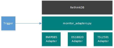
08/20/2016 at 13:21 • 0 commentsToday i soldered together the fan controller as sketched in the last log entry:
![]()
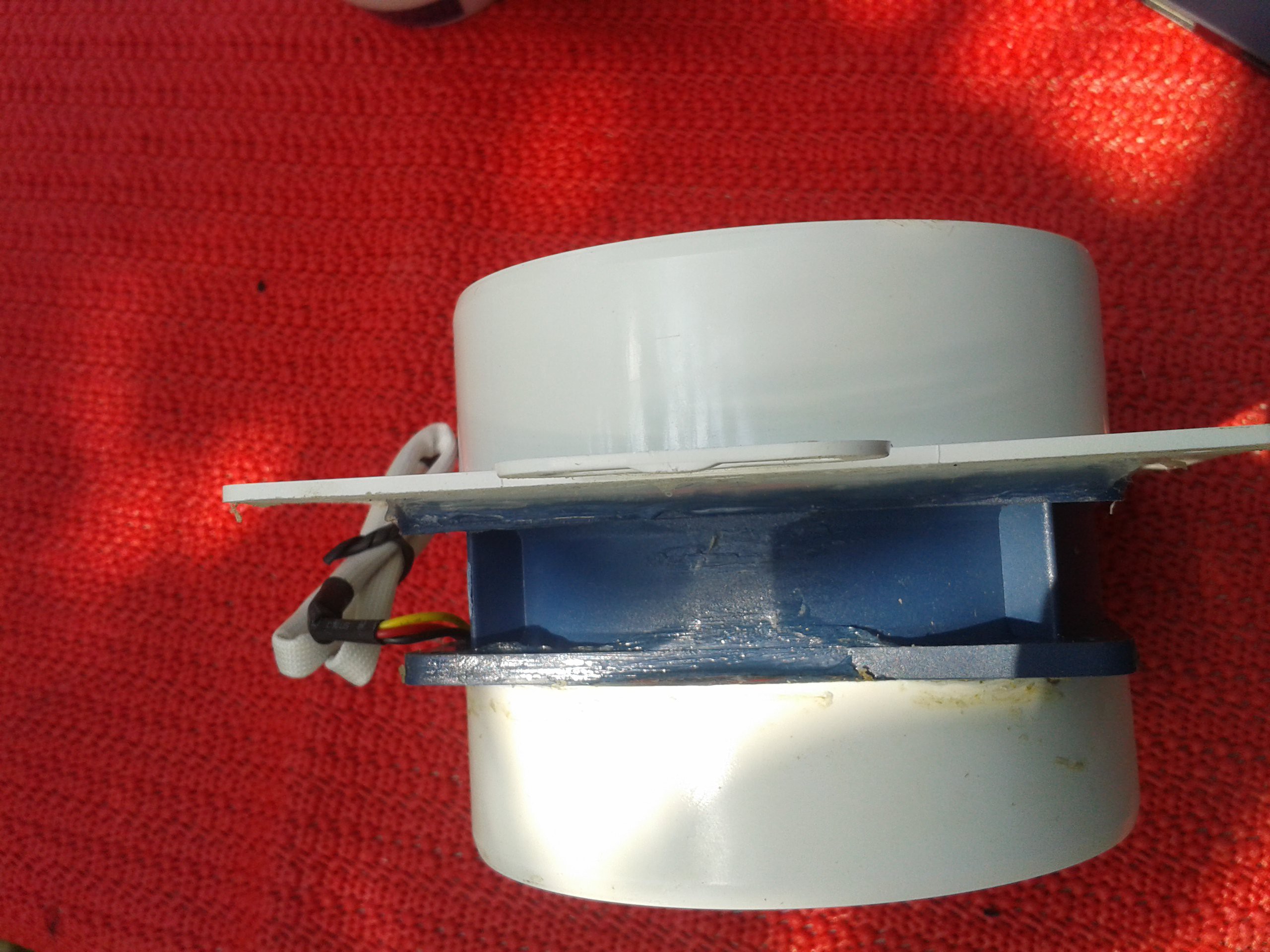
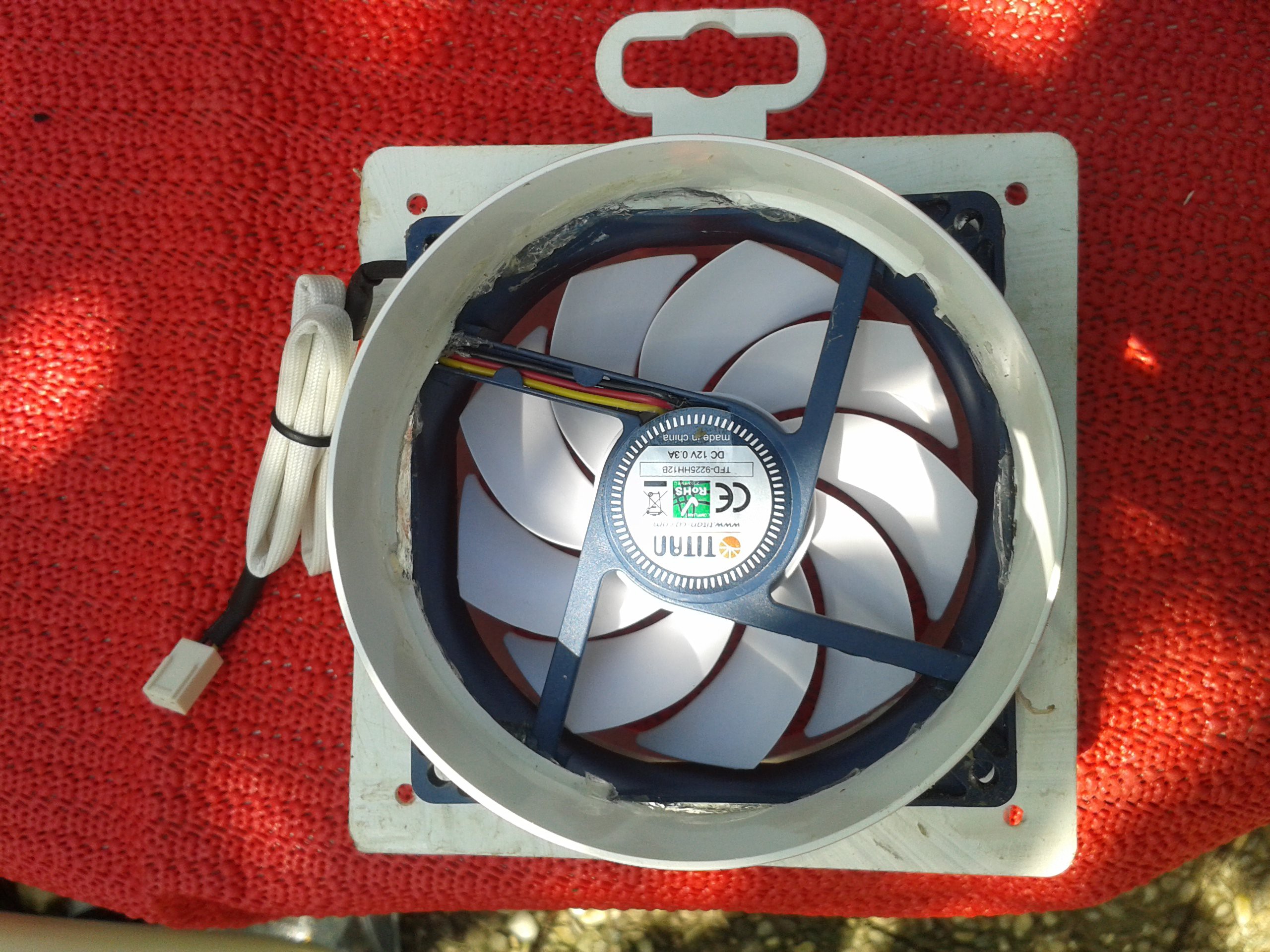
To mount the fan i bought my self a 100mm wall mount for air ventilationand attached the fan to it. To seal it off i used some silican to keep the air outside when the fan is off:
![]()
The first testrun was a success - the fan started to blow air when switching on GPIO 23 (to which the controller is connected via the fan controller above)
![]()
-
Fan Controller - using STP16NF06L
08/18/2016 at 20:21 • 0 commentsSo after having mounted all temperature sensors i started to work on the part which will be driving a fan to cool the greenhouse and to controll the humidity. I decided i have no need for PWM controll of the fan. It is fine that the fan is running full speed all the time as to have an effect at all the fan needs to run full speed anyways.
So i just neded to drive a 12v fan - which requires a Mosfet (i decided to go for the STP16NF06L as it was avialbale at the local store). Very important is the "L" at the end - as there are other version without that available - those are not logic level Mosfet. This would mean they cannot be (fully) triggered using a Raspberry. The STP16NF06L is an N-Chanel Mosfet which potentially could drive up to 45W which is far more than the 4W i will need for one fan. I could easily add another fan just attaching it to the same wire later...
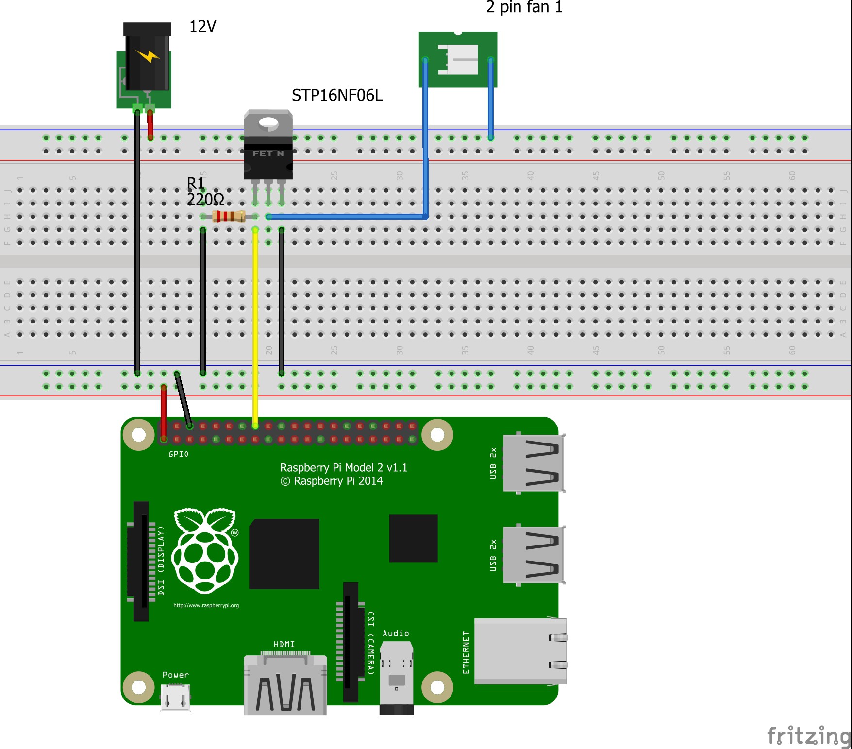
So the layout is pretty straight forward:
![]()
The N-Chanel Mosfet switches Ground whereas the +12V is just passed through to the fan. To make sure we don't get nasty side effects of course Raspberry GND and the GND of 12V supply need to be connected. Of course one GPIO (here GPIO23) is connected to the Mosfet's gate (Mosfet Pin 1) - which is actual the switching port. Last but not least a pull-down resistor is used to make sure that the switch (Gate) is in a defined state (GND) even of the Raspberry GPIO is in input mode.
The Mosfet source (Mosfet Pin 3) and the Drain (Mosfet Pin 2) to the fan's GND in.
That's it and should work nicely.
Tomorrow i'll solder this on experimental board to test it... -
Mounting the sensors and cabeling
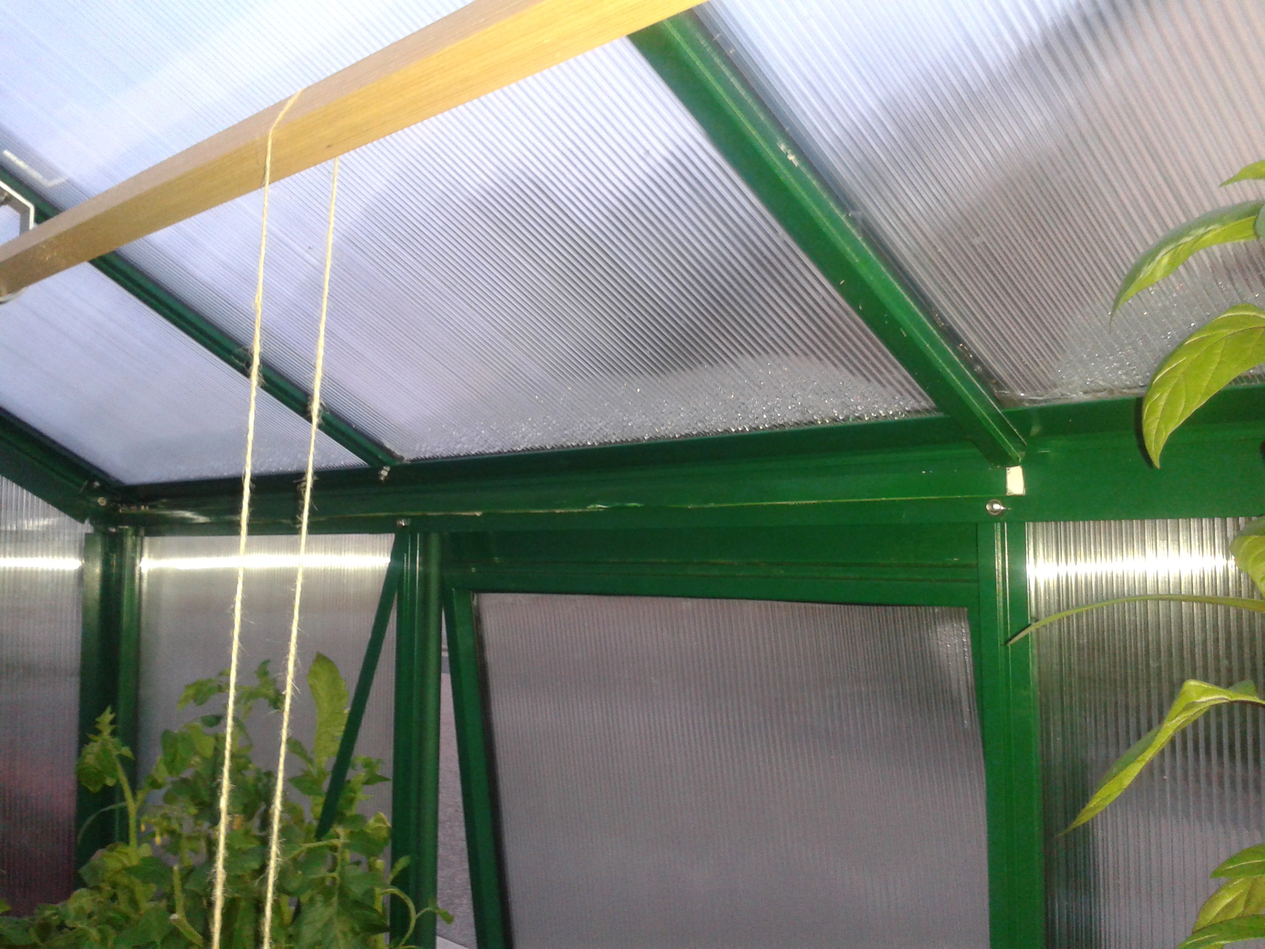
08/16/2016 at 20:46 • 0 commentsSo now that the sensors housings are done (i created three for the temperature sensors - one for rooftop, one for plant height and one for outside temperature - the soil temperature seonsr stays without housing) i started to mount the sensors with their housing in the greenhouse. Therefor i got myself some cheap white cable conduits and some green spray paint (RAL 6005 - which is the same the greenhouse is painted in).
I measured the lenght of cable conduits, made the cut-outs and colored them with the green painting. I decided to just use doublesided tape to fix the conduits for now to fix it to the greenhouse aluminium profiles. Let's see how durable this will be (with the high humidity and high temperature variance it might be a problem later - let's wait and see)
![]()
You can see that they are barely visible against the greenhouse profiles as the color matches very well.
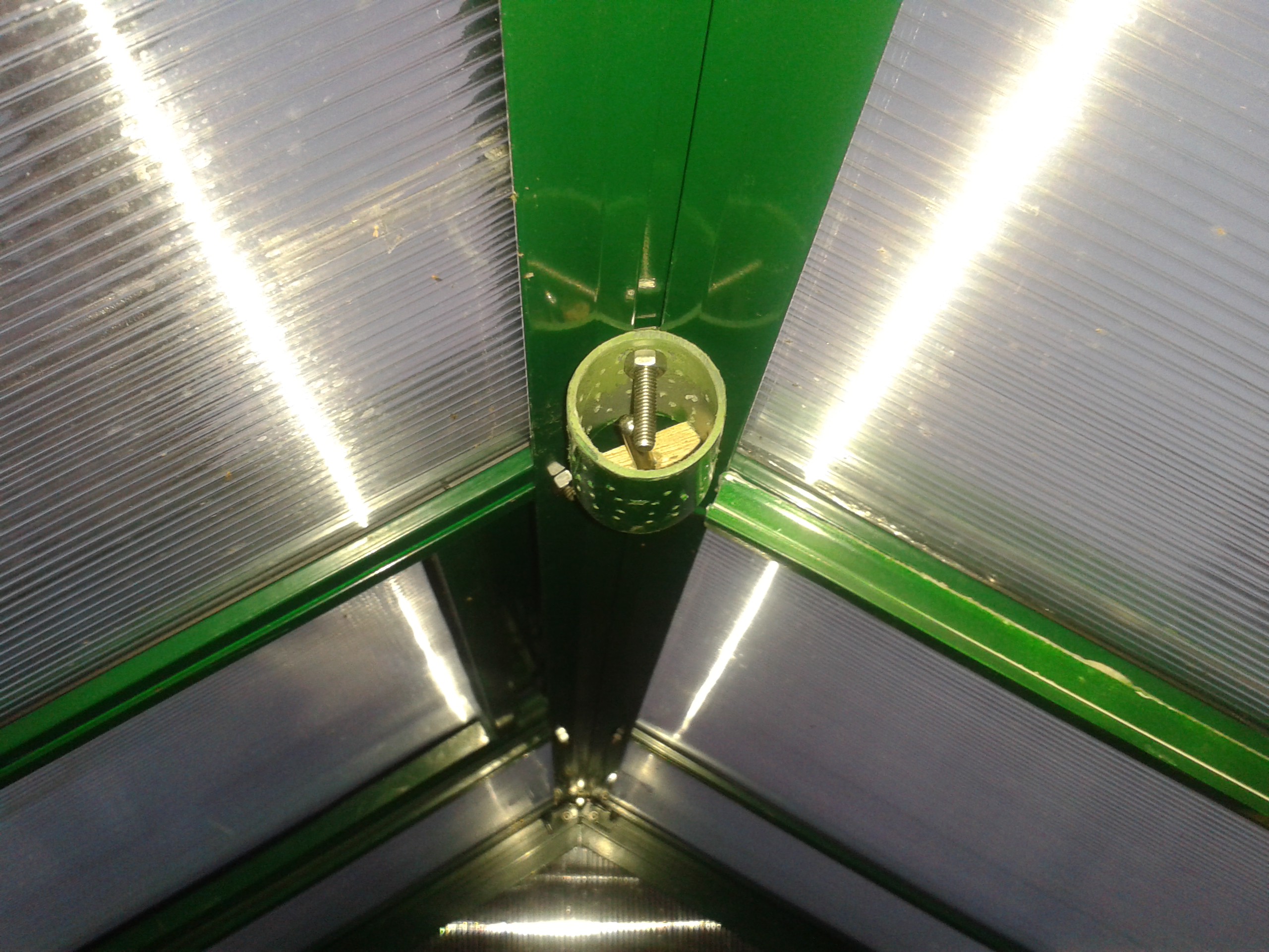
Finally i put up the first sensor housing by dirlling a hole for an M5 screw through the sensor housing, which i used to fix it to the aluminium profile under the rooftop.
![]()
You can see the screw is a little bit long but it is clear from the sensor (metal pin behind the screw) and keeps the housing in place.
The sensor wire i simply had extended by soldering a few meters of 0.5mm wire to each of the three wires of the 1W interface. Unluckily i could not finish the whole business of fixing all sensors (the color of the conduits was not fully dried) - so this has to wait for next weekend. Anyways the proof of concept was successfull - one sensors mounted - all planned parts are at home - so no problem to finish as soon as i have some time to spend. More to come....
-
Integration of electronics into the housing
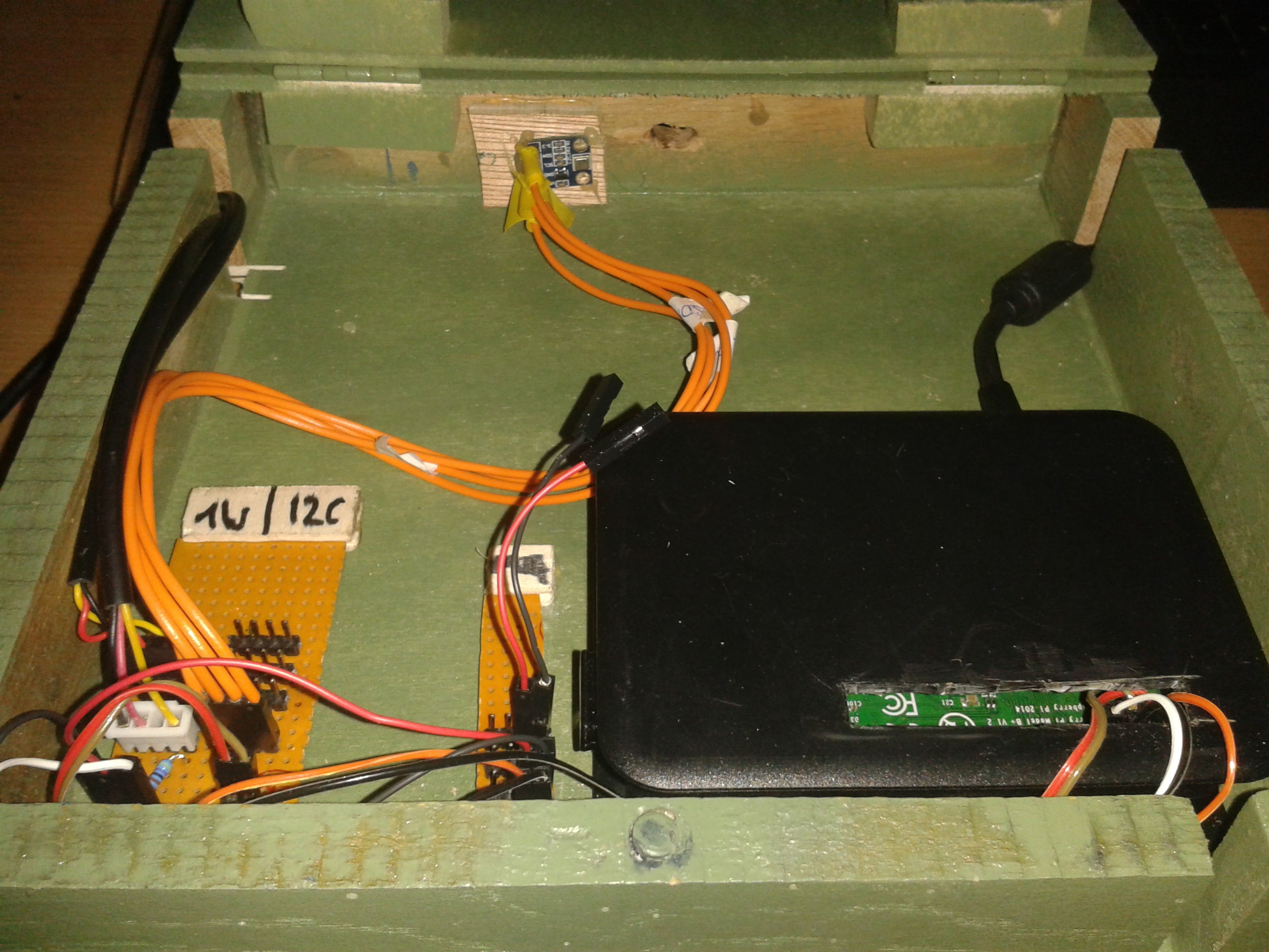
08/06/2016 at 18:33 • 0 commentsToday my goal was to integrate the parts i already have electronically integrated into the housing. The BMP085 pressure sensor stay inside the housing as it should not make any difference for (pressure) measurement whether it is placed inside our outside the housing - and here it is well protected and cables can be arranged permanently. The other sensor should be attached in a way to be able to unplug them - as the whole case is attached via magnets to the board permanently mounted in the greenhouse. This way it is easy to take the PI and all components besides the sensors in house for analysis / further development whereas the sensors can be permantently attached to the greenhouse and only cables will have to be unplugged.
![]()
To the left you see the 1W (with two sensors attached) and I2C (with the BMP085 attached) adapter boards - on top the BMP085. I also added a power adapter board (the small one next to the PI) to be able to drive other components with GND / 3.3V (the two open wires are 3.3V / GND to be used for the DHT11 which is not yet integrated). It is equipped with 4 headed pins to be able to supply 5V and 12V through the spare pins at a later stage.
I'm still thinking of adding other connectors for the sensors outside the case - that would be a next step.
To the right you see the USB power supply cable for the PI which when used in the greenhouse is feed by the battery pack / solar panel.
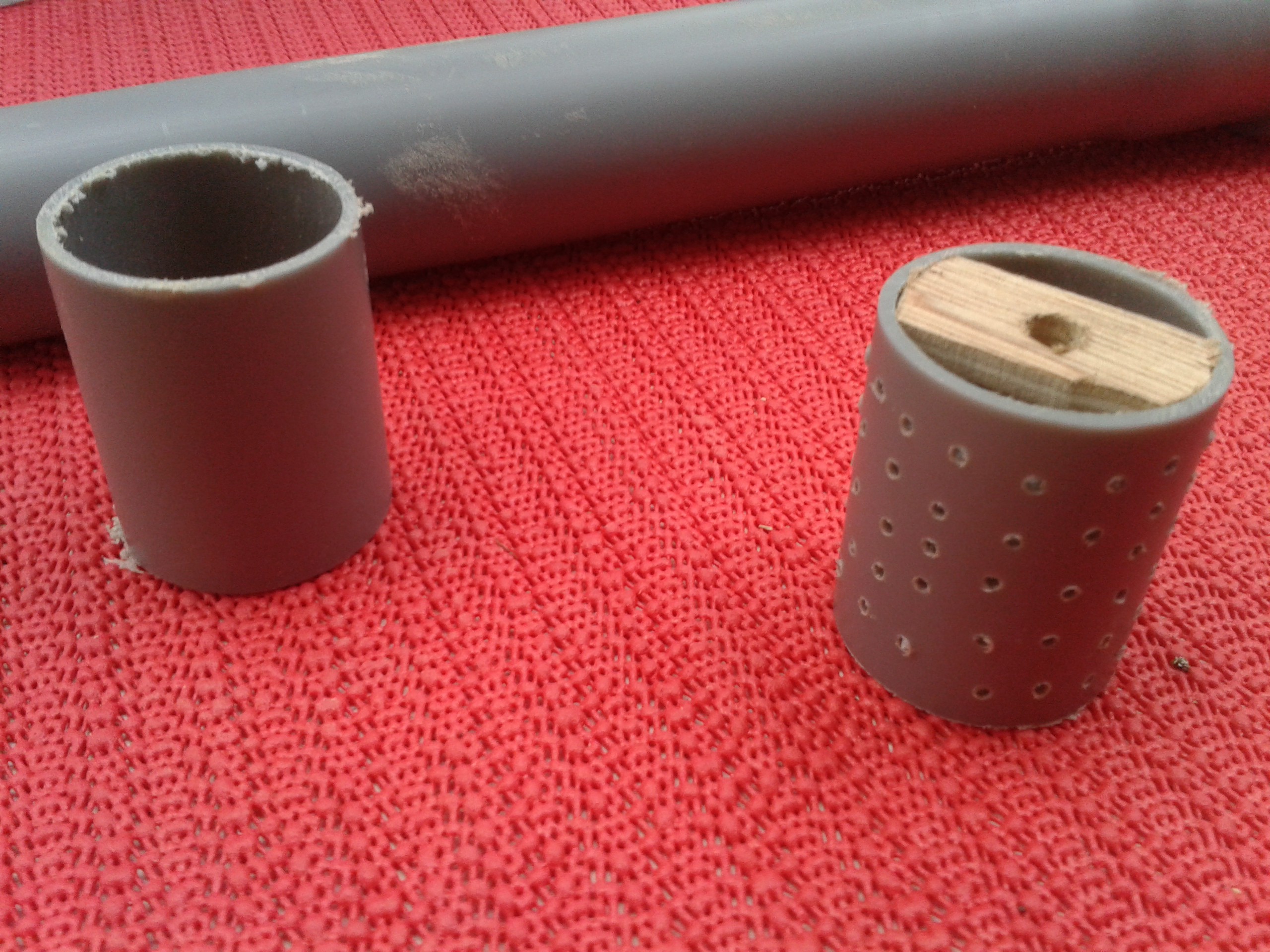
Also i made somee progress with DS18B20 mounts. They tend to react to direct sunlight quite directly - to avoid this i decided to put them in a covering housing - blocking (most of) the sunlight but allowing the housing to "breath" . So i went to the next shop and got myself PVC pipe (4cm diameter), cut it to the right size, drilled some holes into the PVC pipe and put a piece of wood to hold the sensor (with a drilling hole in the middle) which i glued with hot glue.
![]()
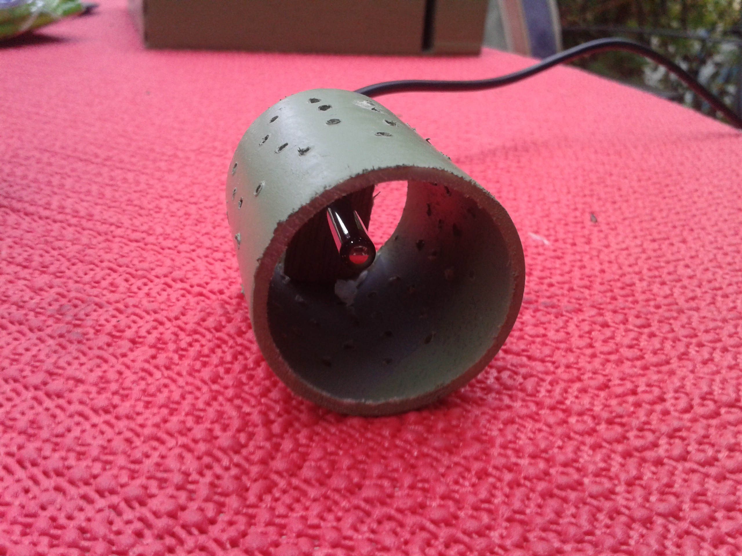
The result after applying a little bit of paint loks like this:
![]()
So still a lot of work to do but there is some progress :-)
-
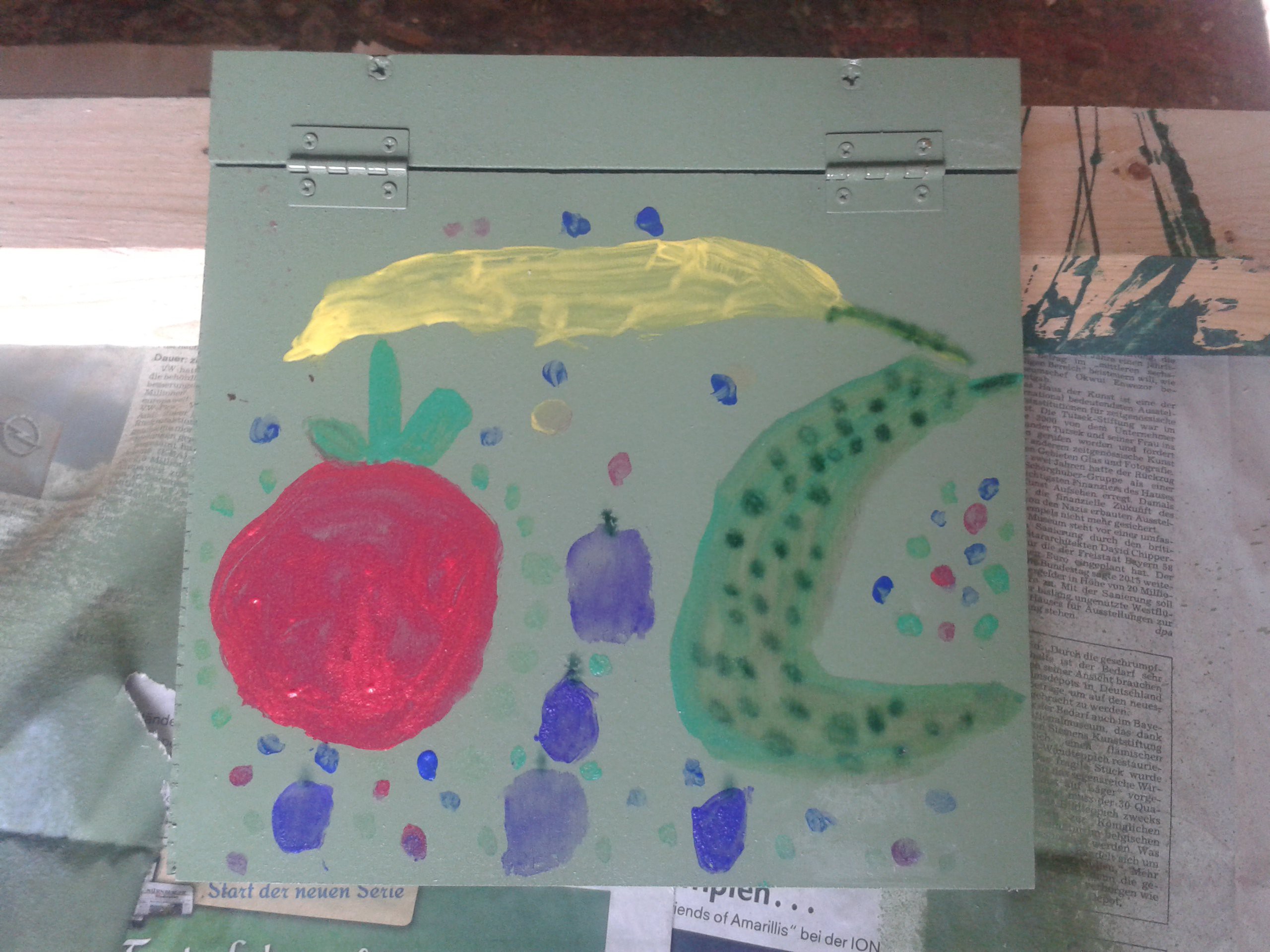
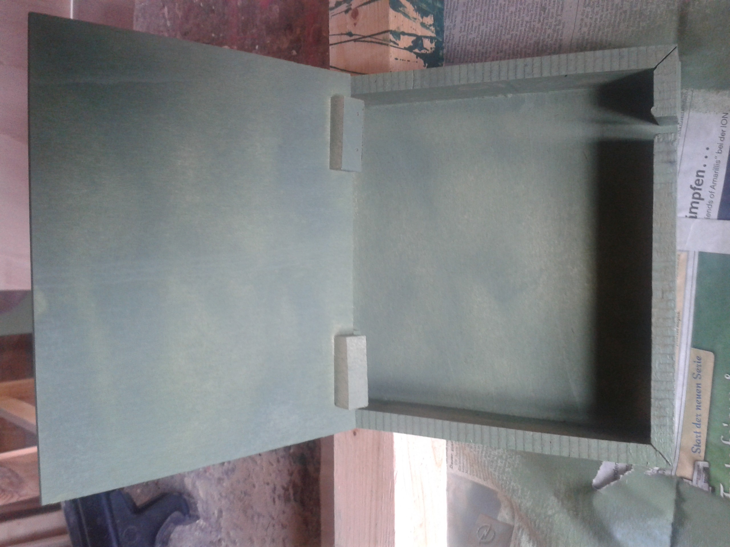
Case painted by my daughter
08/04/2016 at 11:48 • 0 commentsThe case for the Raspi and the adapter boards was painted by my daughter - fitting the greenhouse of course :-)
![]()
It is ready to be mounted and equipped with the Raspi :-)
![]()
-
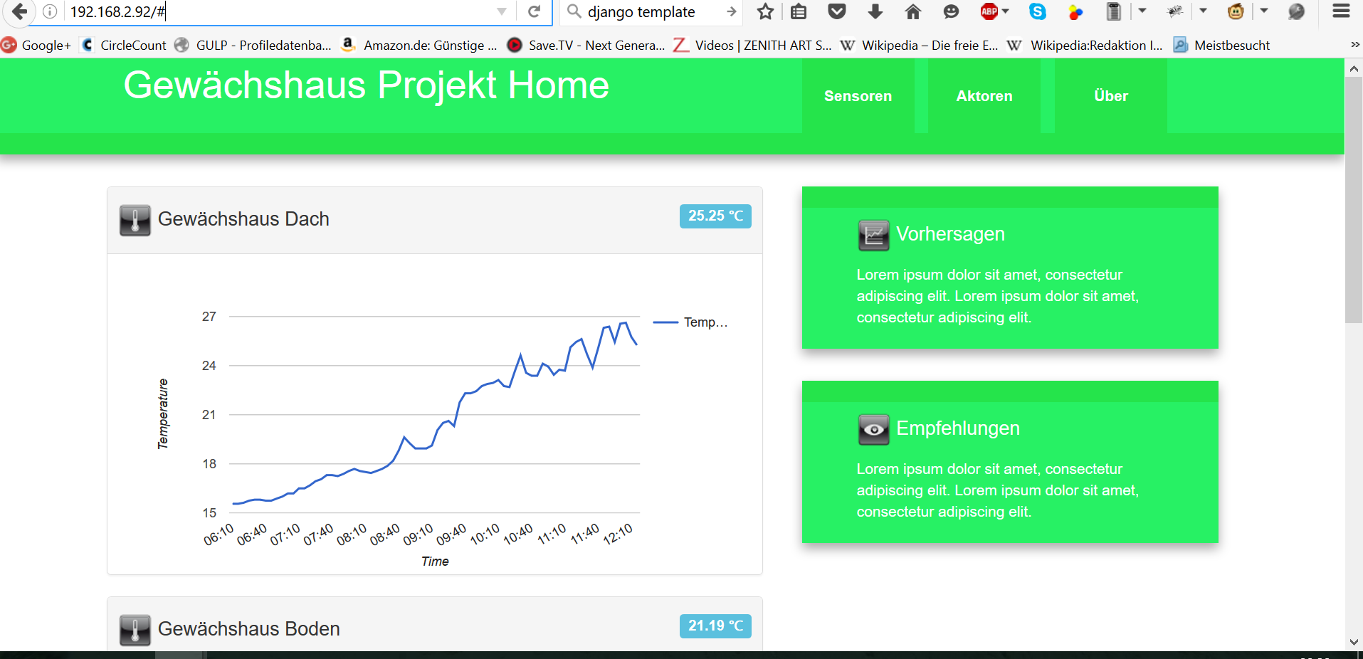
Dashboard design - first version
08/03/2016 at 20:38 • 0 commentsA first version of the web dashboard is ready and under test:
![]()
It is based on Bootstrap - the charts are Google Chart components - the rest is pure javascript. What you can see on the screenshot is a real measurement cycle for one temperature sensor (two DS18B20's and one BMP085 are connected).
I'm still thinking of using some kind of web framework like Django, Angular, Express, Koa, Horizon or something for the dashboard app. There is dozens of those each one with advantes and disadvantages...
Also i'm not happy with the Google charts component: Firstly it needs internet connectitivty to work (no local libary available) and secondly it is not fully responsive (means it does not scale to smallest sized, e.g. for mobile devices correctly)
The backend is also built in a first version based on Python (for the adapters to the sensors), RethinkDB and Tornado for Websockets. I'll add details regarding this and source code as well in a later post. The data pipeline from the hardware sensors to the frontend works although it is not yet perfect of course...
Greenhouse Pi
Solar powered Raspberry Pi measuring greenhouse environmental data and driving some actors