-
Revision 0.3
02/12/2017 at 21:15 • 0 commentsThe revision 0.2 board worked mostly, but has a few issues. One was that idiot me forgot to connect 2 pins to the ground. The other issue is that the LT3081's need a bit of load to regulate to 0V and that the 5V regulator used has a maximum input of 20V.
Revision 0.3 fixes these issues.
The 5V regulator has been replaced by a 78L05, the SOIC version of the well known 7805, which is capable of 30V input. Not perfect but acceptable for now. A SMPS would be a nicer solution in the future.
The problem with 2 gound pins not connected has been fixed. A small power LED has been added as well as an indication the device is powered.
At last a LM2687 has been added to generate -5V at a few mA's This is used to create some load for the LT3081's so the output will regulate to 0V. It's afforable and works perfect for this application.
The new files have been added for the schematic and PCB layout.
On a more interesting note, a PCB that will be used as a front panel containing an LCD, 2 rotary encoders and a uC is being designed, this together with the rev 0.3 VederPSU design will make a more complete and functional lab power supply. Hopefully an update will be here in about a month on that.
-
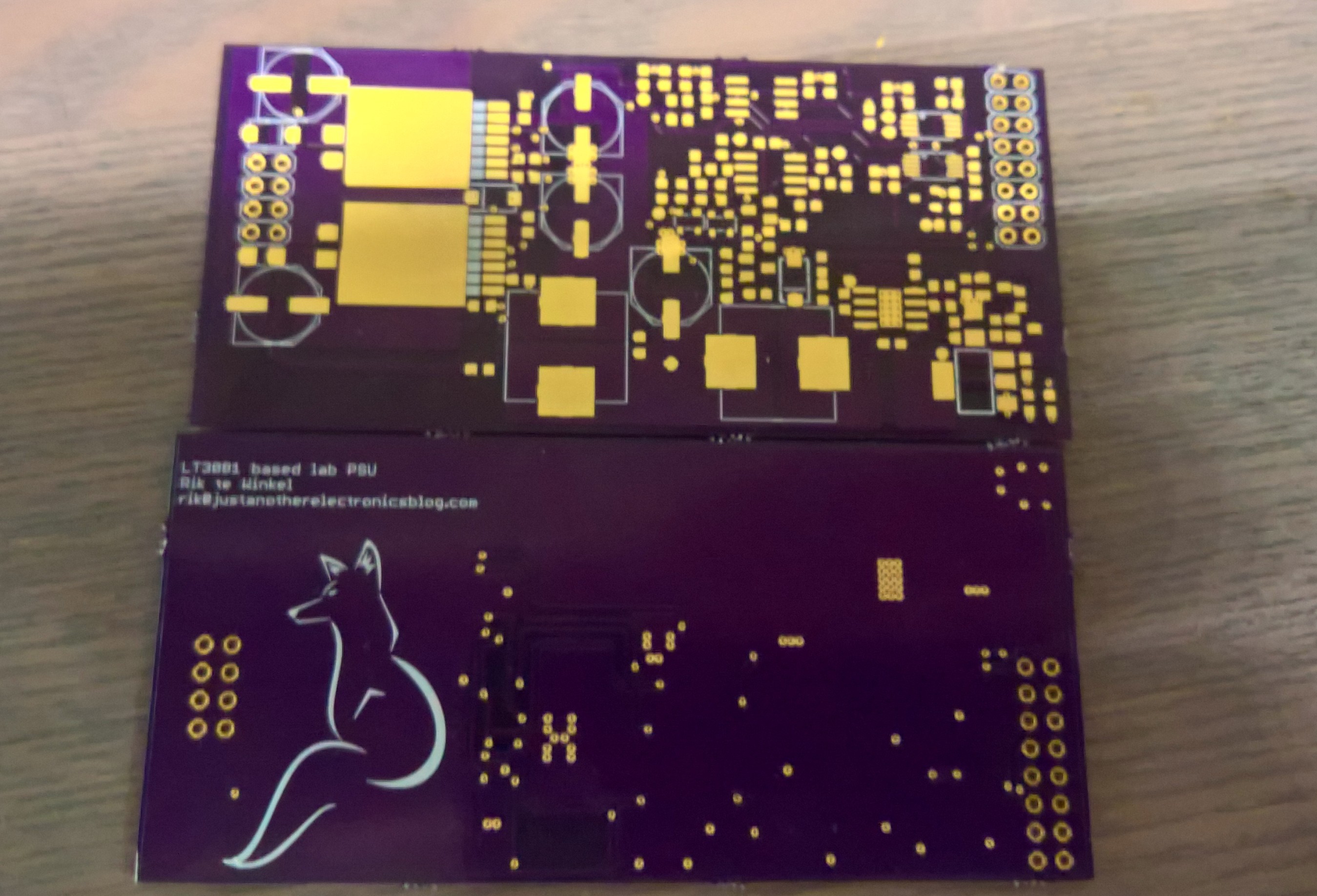
The new board.
07/20/2016 at 21:34 • 0 commentsThe new board:
A few months ago I stumbled across this app note from Linear tech, describing how to build a lab power supply unit with their new LT3081 IC. This IC is very interesting for this application as it already has a current limiting function build in. It also has a temperature sensor build in and a way to monitor the current. This makes it near perfect for a lab power supply. The downsides are the price, the maximum output current and that a slight negative voltage is needed to really regulate to 0V.![]()
Based on the older version of the VederPSU a new schematic was made, using the same DAC and ADC from the old VederPSU but with a different power stage based on the LT3081 app note. The reason for using the same ADC and DAC (the MAX11613 and MAX5802) is that these are one of the very few ADC's and DACs with an I2C interface and a separate voltage reference input. I want a single voltage reference for the whole system to make calibration easier and to be able to pick a voltage reference of choice.
The DAC has 2 outputs, one for the voltage and one for the current. With the current voltage reference they can go from 0 to 4.096V. The voltage output is multiplied by 10 using an opamp to create a 0-40V signal to control the output voltage with. The 0-4.096V for the current is converted to 0-200uA using an opamp. This combined with a current mirror controls the current limit of the LT3081's.
The ADC has 4 inputs, from which one is used as a voltage reference input. The 3 left are used to measure the output voltage, the output current and the temperature of the LT3081's.
The schematics can be found on the project page for anyone who wants to take a look.
-
History
07/19/2016 at 19:35 • 0 commentsi.e. how it started.
A few years ago a classmate and I started slowly working on a portable lab power supply. The initial reason was because at school we where not allowed to drag lab power supplies with us to the project rooms. We had to test in the lab, which was crowded and sometimes full, and work on all other aspects of projects in the project classrooms.
A few revisions later a mostly working prototype was realised but by then I was doing my internship and the project ended up collecting dust, both figuratively and literally. Some info on how it worked can still be found in an old old blog post on my blog: http://justanotherelectronicsblog.com/?cat=3
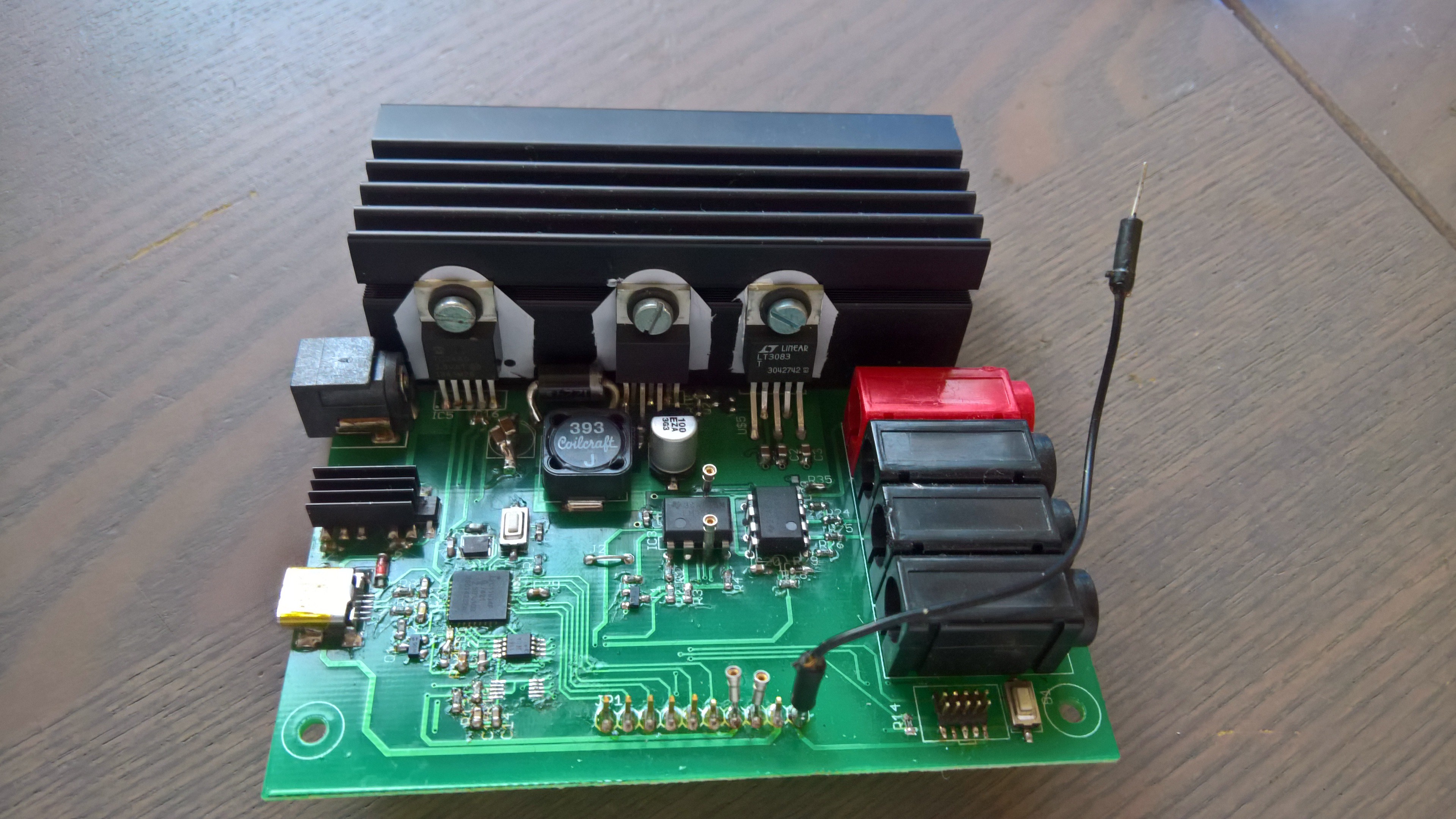
Quickly summarised the last "old" prototype uses an NXP LPC11U37 microcontroller, a maxim ADC and DAC (MAX11613 and MAX5802 because they both have a voltage reference input) and a voltage reference (LM4040) on the microcontroller side. The actual power supply side uses am LT3083 as linear regulator, am LM2670 as switching pre-regulator and a TC74 temperature sensor. To measure the current an LT6105 was used, combined with some opamp magic for current limiting and source/sense measurement.
![The last "old" prototype]()
The last old style prototype of the VederPSU.
As said, this worked reasonably well, apart from noise in current limit mode. I will upload all the files and relevant stuff here or on a github in case it is useful for anyone. The next project log will feature a more extensive write-up of the new hardware and software.