ronald.sutherland
-
^9 KNL setup
06/10/2018 at 21:07 • 0 commentsTwisted the firmware's AVR (it is not an ARM, which I hope to try soon) to get most things to fit in memory, but I did have to nix the Capture CLI commands. I think this is ready to run some valves in the garden.
So I replaced the RPUno^5 that was being used to irrigate a few zones (SxSWEncl).

The RPUno^5 did good and so did the K3 it operated, I got to see a lot of data from it (K3^2+RPUno^5_log).
One thing is clear the Orbit valves do not get stuck when operated like this. I was having a problem where they would get stuck open, most likely that was caused by the hard water mineral build. Perhaps the frequent operation dislodges the buildup before it reaches a critical level. Unfortunately, the valve is no longer on the mainstream market. It received a lot of complaints about sticking (which were true from my experience). Having said that I still like the valve design, it is incredibly fast acting and is clearly durable when used with a frequency beyond what the controller it was sold with did. There are other valve options I will explore when I can.
Every day each of the three valves operated ten times for over a year. When I looked at the data I would cut and past it into the log. That was when I found a number of issues, some were the battery, some were damaged/broken/separated drip lines and the pressure regulators. Basically, the flow count tells me that I need to look for an issue. Zone 3 is going wild, but the emitters seem to be working and nothing I have looked at has failed, so I think the pressure regulator on it is having problems.
-
^9 has a number of changes
04/26/2018 at 00:35 • 0 commentsOne goal of this version is for it to work with the K3 solenoid driver board. The ADC inputs are now level shifted just like the digital IO so they can be used for either function. Each current source can be enabled/disabled so I can reduce power to very low levels if the power source is running low. Finally, the attempt to have a replacement for a solar charge controller function is found as an Alternate power input. The alternate input is a P-channel MOSFET that the microcontroller can enable to let power to the main line which is presumably connected to a battery. The alternate power input has only had basic testing done so I am not sure how useful it will be.
-
^7 removed LT3652
12/11/2017 at 19:40 • 0 commentsI Removed the solar charge controller.
Although the LT3652 works fine, it adds cost, and more importantly does not pay back that cost. Charging an LA battery at a low rate (say 0.02C or less) does not really benefit from having a charge controller, it works fine to just connect the PV to the battery through a blocking diode
Some MCU pins are now free. On ^7 I ran them to a header but I don't like what I did.
I am using the ^7 board I built to run my reflow oven.
I will not offer this verison on Tindie.
-
^5 Baud Rate Framing Error
01/21/2017 at 04:42 • 0 commentsAt 115.2k Bit Rate there is a large framing error (2.1%). I have seen enough errors now to be convinced that I need to use a bit rate that has less framing error. Looking at the Rate Calculator I see 76.8k is very good (0.2%), but the picocom packaged on Ubuntu does not support it. The next very good rate is 38.4k (also 0.2%) which picocom does support. The bootloader does a CRC check with each line in the hex file so running it at 115.2k is ok, it will redo the chunks with errors. However, I don't want to see any errors while running commands (that would look bad during a demo).
Turns out the ideal bit rate to use is 125k or 250k which has 0% error. I am using slew limited 250k RS485 transceivers so that is the max. The released version of picocom does not support custom bit rates. The good news is that picocom custom rates were fixed. All I have to do is wait for the next release after [picocom_2.2] and then Debian needs to pick it up but Debian is still using 1.7 from google code (what a PITA).
Note: Baud is the wrong term, but is the one everyone knows.
It may be helpful to understand that the start and stop bits make up the framing system, and having little idle time between transmissions may help push the system into less stable operation. I think this is why I was seeing errors when I cut-and-paste into picocom at 115.2k, there were never errors when typing directly or when only a few characters were paste.
-
^5 Power Management
01/08/2017 at 02:43 • 0 commentsThe RPUno controls power from the battery to its VIN pin with digital IO2. On the RPUpi shield that power is provided to an SMPS that provides 5V at up to 1A to the Pi Zero header. Wait... don't just pull the plug, the correct way is to halt the Pi Zero and then wait for it to stop. The time it takes to halt depends on the running applications. The best handshake I have figured out is to wait for thirty seconds and then watch that the load current from the RPUno battery has stabilized as demonstrated with this Power Management firmware.
The RPUpi has a shutdown button that pulls down BCM6 (header pin 31) on the Pi Zero. BCM6 is used by a Python Shutdown script to halt the computer. For testing, I've loaded the bus manager with the Remote* firmware that places a weak pull up on its PB0 (ICP1) pin which is also tied to that BCM6 pin through a 1.8k resistor. As a result, both a manual or bus manager initiated halt can occur. The RPUno must check for a manual halt by reading the shutdown_detected flag from the bus manager as demonstrated with the Power Management firmware.
The RPUno also controls power to the FT/Pulse sensor current sources with digital IO9 and is also demonstrated with the Power Management firmware.
-
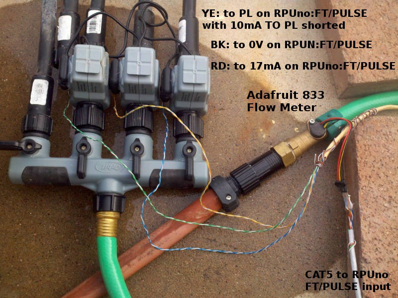
^5 Flow Meter
12/16/2016 at 05:50 • 0 commentsWith the solenoid setup working it is time to initialize ICP1 and add Capture commands to the Solenoid program, which allows connecting a flow meter to the pulse capture input to see the pulse counts from the flow meter. I have an Adafruit PID:833 meter that has a small turbine and a hall sensor with an open drain output. Each pulse is about 2 milliliters. After the initialization that happens when reset occurs I see over 400 pulses went through each zone (e.g. in 1 second).
![]()
![]()
/1/flow? 1
{"K1":{"cycle_state":"0","cycles":"0","flow_cnt":"405"}}
/1/flow? 2
{"K2":{"cycle_state":"0","cycles":"0","flow_cnt":"415"}}
/1/flow? 3
{"K3":{"cycle_state":"0","cycles":"0","flow_cnt":"414"}}
The Capture program has the capture unit prescale set to the MCU clock speed, so that was what I started with for the Solenoid program. The event timing shows the prescale needs set, which will not change the counts only the event times. The status also shows both rising and falling edge was captured, and that is a wake up call... I am counting both events (opps).
/1/event? icp1,6
{"icp1":{"count":"1643","event":"51796","status":"1"}}
{"icp1":{"count":"1642","event":"20072","status":"0"}}
{"icp1":{"count":"1641","event":"8183","status":"1"}}
{"icp1":{"count":"1640","event":"60309","status":"0"}}
{"icp1":{"count":"1639","event":"52793","status":"1"}}
{"icp1":{"count":"1638","event":"53660","status":"0"}}
/1/initICP icp1,rise,3
/1/run 1
{"K1":{"delay_start_sec":"3","runtime_sec":"10","delay_sec":"40","cycles":"10"}}
/1/stop 1
{"K1":{"stop_time_sec":"3"}}
/1/run 1,1
{"K1":{"delay_start_sec":"1","runtime_sec":"1","delay_sec":"1","cycles":"1"}}
/1/flow? 1
{"K1":{"cycle_state":"0","cycles":"0","flow_cnt":"244"}}
/1/event? icp1,31
{"icp1":{"count":"793","event":"29682","status":"1"}}
{"icp1":{"count":"792","event":"56369","status":"1"}}
{"icp1":{"count":"791","event":"40079","status":"1"}}
{"icp1":{"count":"790","event":"30084","status":"1"}}
{"icp1":{"count":"789","event":"23288","status":"1"}}
{"icp1":{"count":"788","event":"18644","status":"1"}}
{"icp1":{"count":"787","event":"15244","status":"1"}}
{"icp1":{"count":"786","event":"12683","status":"1"}}
{"icp1":{"count":"785","event":"10543","status":"1"}}
{"icp1":{"count":"784","event":"8676","status":"1"}}
{"icp1":{"count":"783","event":"6931","status":"1"}}
{"icp1":{"count":"782","event":"5256","status":"1"}}
{"icp1":{"count":"781","event":"3614","status":"1"}}
{"icp1":{"count":"780","event":"2017","status":"1"}}
{"icp1":{"count":"779","event":"432","status":"1"}}
{"icp1":{"count":"778","event":"64420","status":"1"}}
{"icp1":{"count":"777","event":"62890","status":"1"}}
{"icp1":{"count":"776","event":"61391","status":"1"}}
{"icp1":{"count":"775","event":"59886","status":"1"}}
{"icp1":{"count":"774","event":"58407","status":"1"}}
{"icp1":{"count":"773","event":"56932","status":"1"}}
{"icp1":{"count":"772","event":"55480","status":"1"}}
{"icp1":{"count":"771","event":"54010","status":"1"}}
{"icp1":{"count":"770","event":"52560","status":"1"}}
{"icp1":{"count":"769","event":"51093","status":"1"}}
{"icp1":{"count":"768","event":"49635","status":"1"}}
{"icp1":{"count":"767","event":"48173","status":"1"}}
{"icp1":{"count":"766","event":"46714","status":"1"}}
{"icp1":{"count":"765","event":"45234","status":"1"}}
{"icp1":{"count":"764","event":"43767","status":"1"}}
{"icp1":{"count":"763","event":"42286","status":"1"}}
This is good feedback, each zone has a flow count to show it is working. I have also used this meter on a previous setup and the numbers look reasonable. Some things to note. One is that as the valve is closed the time between events will cause the 16-bit timer to overflow for the most recent events (even with prescale set at MCU clock/64). Another is that I have a nasty turbulent flow going through the turbine that spins a magnet and triggers the hall sensor, so the timing has astonishingly high jitter (which indicates issues with pulse interpolation techniques).
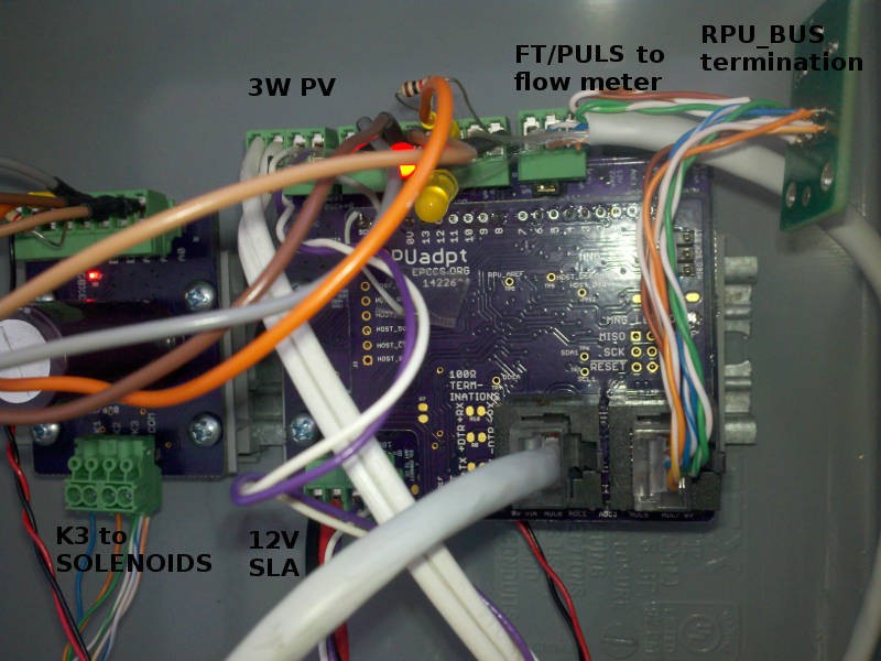
After a rebuild and upload. Remember I'm sitting at my desk using an SSH session to the Linux box on my test bench, which is connected to an RPUftdi shield that has a CAT5 cable going out to the RPUno with an RPUadpt shield in the garden... I almost feel like I have a clue what I'm doing. But it fades fast when I find the board on my bench got the update because I forgot to tell the bus manager which device I wanted to load and thus nuked the i2c-debug program on the bench board that is used to tell the RPUftid bus manager what remote address to load. Clearly, this needs improvements.
I operate the valves manually by loading settings from the EEPROM and running them. Ten cycles of 10 Second duration spread by a 40 Second delay between cycles. The delay_start only occurs once so that I can start the watering cycles later in the day when it gets warm.
/1/load 1
{"K1":{"delay_start_sec":"3","runtime_sec":"10","delay_sec":"40","cycles":"10"}}
/1/run 1
{"K1":{"delay_start_sec":"3","runtime_sec":"10","delay_sec":"40","cycles":"10"}}
/1/load 2
{"K2":{"delay_start_sec":"16","runtime_sec":"10","delay_sec":"40","cycles":"10"}}
/1/run 2
{"K2":{"delay_start_sec":"16","runtime_sec":"10","delay_sec":"40","cycles":"10"}}
/1/load 3
{"K3":{"delay_start_sec":"29","runtime_sec":"10","delay_sec":"40","cycles":"10"}}
/1/run 3
{"K3":{"delay_start_sec":"29","runtime_sec":"10","delay_sec":"40","cycles":"10"}}
Wait for 10 minutes while it runs
/1/flow? 1
{"K1":{"cycle_state":"0","cycles":"0","flow_cnt":"16335"}}
/1/time? 1
{"K1":{"cycle_state":"0","cycles":"0","cycle_millis":"100000"}}
/1/flow? 2
{"K2":{"cycle_state":"0","cycles":"0","flow_cnt":"17773"}}
/1/time? 2
{"K2":{"cycle_state":"0","cycles":"0","cycle_millis":"100000"}}
/1/flow? 3
{"K3":{"cycle_state":"0","cycles":"0","flow_cnt":"17076"}}
/1/time? 3
{"K3":{"cycle_state":"0","cycles":"0","cycle_millis":"100001"}}
So that is about 34 Liters (9 gallons) to each zone during a 100 second period. The flow_cnt could be calibrated to figure out the flow meter K factor, but that is not a concern yet.
-
Version ^5 Adc and Digital
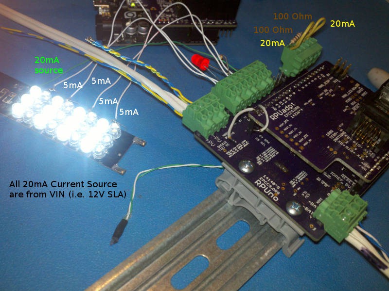
11/22/2016 at 07:08 • 0 commentsInteractive command line programs for the ADC
https://github.com/epccs/RPUno/tree/master/Adcand Digital input/output
https://github.com/epccs/RPUno/tree/master/Digital
I like a command line interface, it started with old school GPIB instruments, but now that I have been exposed to the very infectious ideas of JSON the beauty of a ReSTful SCPI(ish) instrument for the garden is complete.
![]()
-
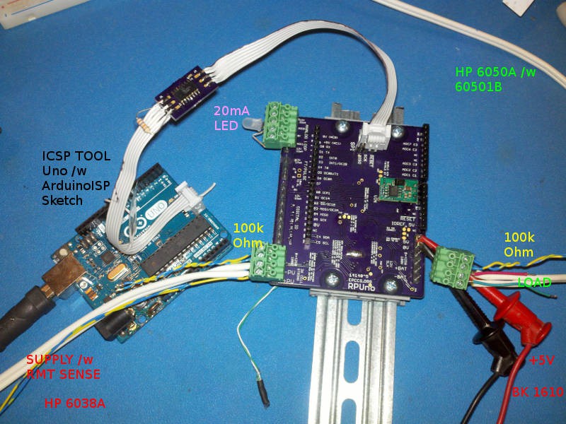
Version ^5
11/11/2016 at 18:51 • 0 commentsAssembled Version ^5 and did some Testing. Found a solder bridge near the LT3652 timer pin but that is nothing new. I think a stencil would help, rather than the syringe for solder paste. Ran the electronic load in voltage mode at 12.8V to simulate a battery and a supply set for 20V@1.1A to simulate the PV. Moving the shutdown thermistor (the green and white twisted wires from under board) off board looks like it can run all day at 1.3A. This is good news for the RPUpi board.
![]()
-
Version ^4
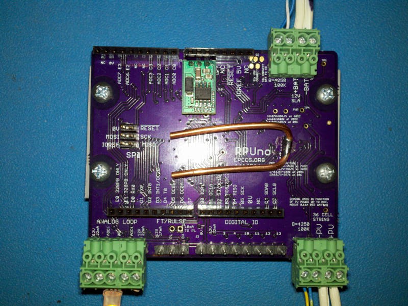
09/24/2016 at 07:15 • 1 commentAssembled version ^4 of this board, it changed the battery from 6V to 12V, and adds pluggable connectors. There are six digital inputs, a flow sensor input and two analog inputs for 4-20mA type sensors. These all need evaluation but I got to say I am itching to see if it will provide enough power for a Raspeary Pi Zero setup I am working on. In this image, I have added a copper wire to wick some heat from the solar charge controller.
![]()