Close
0%
0%

Split Flap Display

This display is being design and built for a local dance company as a set piece, exploring the concept of travel and transit.

mlomlo
Similar projects worth following
This Project will document the development and design details of our Split Flap Display Board. The goal is to allow others to build their own individual modules and displays!

Microcontroller - Arduino Mega: We went with the Arduino Platform because we chose Adafruit Motor-shields to drive all the stepper motors.

Motor Driver - Adafruit Motor-shield V2:  We went with this off-the-shelf solution because of it's ability to simply add additional motors by stacking shields.  Since it communicates through I2C the wiring would be much simpler and it was cost effective.

Arduino Libraries - Accel Stepper: This library gave us the ability to simultaneously control multiple stepper motors. It also seemed to play nice with the Adafruit Motorshield.

Motor - 200 step/rev Bi-Polar Stepper Motor:  We went with stepper motors because they had good accuracy, and reasonable balance between torque and speed. Conveniently, they worked nicely with the motor drivers, so this was an easy choice.

Card Holder - Laser cut Plexiglas:  The card holder was the most important part of the design.  Hand cutting wheels out of wood and drilling the individual holes in a drill press became tiresome quickly.  Plexiglas was chosen because we thought it would stand the humidity better than wood.

Cards - Hand-cut Screen Printed CR-80 30mil PVC: My personal favorite design choice. These standard cards can be purchased for less than 10 cents a piece and gave us the durability and sound we needed.  The material was easy to work with in terms of cutting them to spec and screen printing them.

Module Enclosure - CNC Baltic Birch:  Accuracy and repeat-ability were key, so we needed to get the modules done through CNC.  Baltic Birch was a step up from our original prototypes using Luon or Plywood, and could withstand humidity better.

Power Transmission - 2.5:1 Pulley/Belt System:  It was tough to source out reasonably priced gears and I was concerned about how accurate we could install them.  Pulleys and belts were a lot cheaper and my gearing ratio was driven by what was available through 3D Printer Suppliers.

Power Supply - 12V 30A Meanwell: Each bank of 16 Modules would pull around 12A. This power supply was reasonably priced and readily available through LED suppliers.

Home Sensor - Reed Switch and MCP23017:  Mechanical switches were hard to position inside the individual modules.  A reed switch with an adjustable magnet on the cardholder would allow us to calibrate each box.  This still seems like the easiest and cheapest solution that has given us positive results so far.  In addition, the MCP23017 I/O Expander was chosen because it communicated through I2C and conveniently gave us 16 inputs that could act as Pull-ups.

Wiring - CAT5 and Patch Panels: Individual connectors seems excessively expensive so I decided upon using a pre-built existing solution.  I've read of people using CAT5 to transmit power in their LED installations, but made sure the the wires could support the power to the stepper motors.

  • 4 × Arduino Mega Each Mega would control set of 16 Stepper Motors
  • 64 × Stepper Motor - 200 steps/rev, 12V 350mA This will drive a single module in our split-flap display
  • 32 × Adafruit Motor Shield V2 for Arduino Used to drive all of our Stepper Motors, communicates through I2C
  • 4 × MCP23017 I/O Expander to find Home Position
  • 64 × Reed Switch Used to find Home Position

View all 7 components

  • Are you too Good for Your Home?

    mlo07/19/2014 at 22:50 1 comment

    ANSWER ME!  Bonus points for getting the reference.

    This Project Log comes in between 5/6/2014 to 5/8/2014.  I feel that it is notable because the solution became very simple and elegant.

    Problem:  How should the Split-Flap Modules figure out their home position?

    Potential Solutions:

    -Optical Encoder:  Extra hardware seemed expensive, but I didn't research the specifics.  I believe 3D printers use some sort of Optical Encoder to find their 'Home' positin. Since I sourced a majority of my electronics from Adafruit, I continued on with the other solutions.  

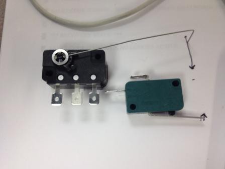
    -Mechanical Limit Switch:  In the beginning, I really thought this was the solution.  It seemed simple and the switches themselves weren't very expensive.  I especially enjoyed the satisfying click each one made.

    It turned out positioning them inside the box was extremely difficult.  I couldn't reliably set them in the same position AND I couldn't guarantee that each module would be made to be the exact same.

    -Magnetic Contact Switch:  In the same Adafruit order, I bough one Magnetic Contact Switch to play with.  At $4.00 a piece, it was a bit more expensive than the Mechanical Switches.  Placing it on the side wall of the module was also difficult, but Brandon (co-owner of the Inman Park Workshop), suggested using foam! Being in a workshop that specialized in making puppets, we were in no short supply of the wonderful pink stuff.

    With the sensor now positioned, when the magnet passed by the switch it would 'make' a connection to ground.  This 'ground' signal would let the Arduino know to stop the Stepper Motor and reset all it's positional data.
    Rather than adjust the position of the Magnetic Sensor, we added a washer to give us the ability to calibrate the exact home position.

    Simple enough eh?  I'd love to hear your solutions!

  • The Beginning

    mlo06/23/2014 at 03:17 0 comments

    All this is being done for a set piece for a local Atlanta Dance Company called Lucky Penny.  It sounded like an amazing project and I was hooked from the beginning.  Too bad I didn't find out about it sooner as we had about 2.5 months before to showing!

    Future Note: This is just one of many set pieces being made for the performance.  Their last performance involved constructing a two story house out of cardboard, strong enough to support dancers!  Please check out our current campaign on Indiegogo and find more about The Lucky Penny here.

    These split-flap displays are truly mesmerizing and the sound they make are delightful!  I did some research and there didn't seem to be much in the way of instructions to make your own.  Most posts deal with reviving existing displays.  My best point of reference was from Richard and his post on Instructables "Arduino based Split-Flap game".  Tom's blog on split-flaps also served as excellent inspiration to create our own. 

    I was also a big fan of the follow videos/links:

    Stanford Enormous Color Split Flap

    Markus' DIY Split-flap display driving circuit

    ‘Signal to Noise’ by LAb[au] – 512 mechanical Split-Flaps

    Hooked on Split Flaps yet?

    I quickly decided upon the parts I wanted to use.  I started off with an Arduino Uno, Adafruit Motor Shield V2, Stepper Motor, and some Pulleys from a 3D printer supplier. This was my first true introduction to the Arduino Platform, so I had a lot of work and learning ahead of me.

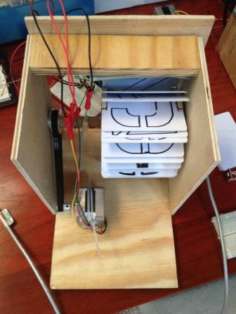
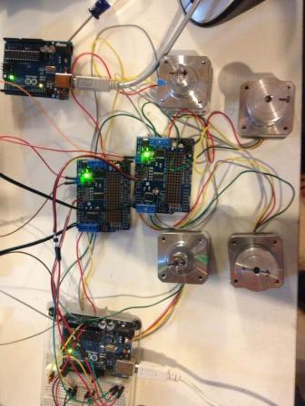
    It was fairly easy getting all the stepper motors to turn, below is a picture of my original set up.

    Now that I had the motors turning, it was time to construct the modules themselves!  A workshop, some plans, and resourceful folk turned out the original versions.  I won't go into too much detail about the dimensions until the later posts for the final design.
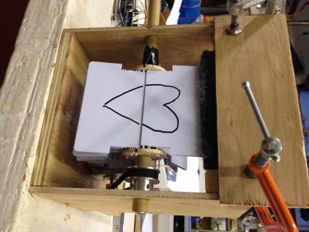
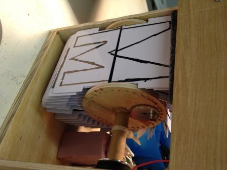
    The card-holder are from 1.5 inch blanks found at Lowes.  I was able to hand-drill 18 holes into two blanks.  The cards themselves were carefully/poorly cut from a band-saw to some questionable dimensions.  The initial prototype cards were printed with lovely permanent marker, it was sad that I had the best handwriting out of our group of three.  The gray felt on top allowed us to adjust the amount of turns it took to display a single character.

    Amazingly it worked, and it gave us the energy to quickly build one more prototype.  We used a 3-inch hole saw, a protractor, a drill-press, and a awl to be able to make a better card-holder. I also went ahead and bought some stencils to give a cleaner look to the cards.  See Video below.

    At this point, my program was barely hobbling along.  My background is EE and it's been a while...  My only text entry was through the Serial Monitor on the Arduino IDE.  It only accepted positional data so I had to calculate the positions for each module.  Even worse, the mapping was off-set since it had a different amount of cards in the card holder.

    Regardless, after about an hour, we exhausted the amount of two letter words we could display and stored them away in a text file to show the team!

    Bonus Note:  The prototype on the right was named Tiny.  His original construction still exist and I use him constantly as a tester.  The one of the left never got a name, he was taken apart in following couple of days to refine measurements.

    Onward and upwards to prototype set of 16!

View all 2 project logs

Enjoy this project?

Share

Discussions

ahmetkardes5 wrote 04/22/2016 at 23:38 point

I did I, but I can not do the software. Can you send me the code ?

  Are you sure? yes | no

ahmetkardes5 wrote 04/22/2016 at 23:37 point

I did I, but I can not do the software. Can you send me the code ?

  Are you sure? yes | no

Ray Weston wrote 06/29/2015 at 20:36 point

Like the others, I'm very impressed with what you've done here and I'm still hoping you'll publish your project logs.  In the mean time, perhaps you can satisfy some curiosities.  Do the displays use one CR-80 card per letter (cut in half) or two cards stacked top and bottom with adjoining edges trimmed to eliminate the radius corners?  I assume that when you trimmed out the area to fit over the card holder wheel, you left a small tab to fit into the holes in the card holder.  Is that right?  Has that proven to be reliable?  I'd expect small tabs of thin PVC to wear away.  I've seen other projects that mention using a wire as an axle for the card but I don't know how they attached that.  Did you print the cards before you trimmed them?  Did you print them one at a time or did you make a single screen with all letters, numbers and symbols for a full set of cards?

Regards,

Ray

  Are you sure? yes | no

mlo wrote 07/10/2015 at 02:19 point

Hi Ray! Thanks for your interest.  I tried to answer your questions below, let me know if you have any more questions, thanks!

1.  We used two cards stacked top and bottom.

2. Correct, we used a jig and a router to cut ~400 cards at once to specifications.

3. Overall, I'd say the cards were "OK" reliable.   I performed a burn-in test where each box went through at least a thousand rotations and 6 or so cards fell out.  During the performances we lost a card or two, but it was interesting to see it flutter to the floor among a group of dancers.  For a quick repair, super glue and some thing fiberglass rod worked great!  From my observations, the failed card tabs were more brittle than soft.

4/5.  We cut the cards then screen printed them in sets.  It was very labor and time intensive, but we had great volunteers.

  Are you sure? yes | no

Stefan-Xp wrote 01/27/2015 at 19:32 point

@Jasmine is right, where are the Vids? ;-)

  Are you sure? yes | no

mlo wrote 01/27/2015 at 22:41 point

XD I'm super behind on my documentation, but luckily hand-wrote all my ideas for project logs somewhere...

In the meantime!

Prototype 16:

Full Display for Performance:

Thanks!

  Are you sure? yes | no

Stefan-Xp wrote 01/28/2015 at 17:46 point

Wow soooo awesome! 8-)

Looking forward for your Project Logs ;-)

Best regards, Stefan

  Are you sure? yes | no

davedarko wrote 01/29/2015 at 00:05 point

Awesome!

  Are you sure? yes | no

Jasmine Brackett wrote 01/26/2015 at 22:39 point

Nice work. It would be fantastic if you have any more video of it in action.

  Are you sure? yes | no

Similar Projects

Does this project spark your interest?

Become a member to follow this project and never miss any updates