 mlo
mlo-
Are you too Good for Your Home?
07/19/2014 at 22:50 • 1 commentANSWER ME! Bonus points for getting the reference.
This Project Log comes in between 5/6/2014 to 5/8/2014. I feel that it is notable because the solution became very simple and elegant.
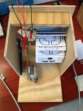
Problem: How should the Split-Flap Modules figure out their home position?
![]()
Potential Solutions:
-Optical Encoder: Extra hardware seemed expensive, but I didn't research the specifics. I believe 3D printers use some sort of Optical Encoder to find their 'Home' positin. Since I sourced a majority of my electronics from Adafruit, I continued on with the other solutions.
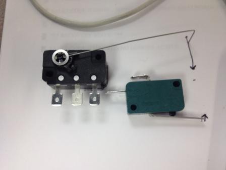
-Mechanical Limit Switch: In the beginning, I really thought this was the solution. It seemed simple and the switches themselves weren't very expensive. I especially enjoyed the satisfying click each one made.
![]()
It turned out positioning them inside the box was extremely difficult. I couldn't reliably set them in the same position AND I couldn't guarantee that each module would be made to be the exact same.
-Magnetic Contact Switch: In the same Adafruit order, I bough one Magnetic Contact Switch to play with. At $4.00 a piece, it was a bit more expensive than the Mechanical Switches. Placing it on the side wall of the module was also difficult, but Brandon (co-owner of the Inman Park Workshop), suggested using foam! Being in a workshop that specialized in making puppets, we were in no short supply of the wonderful pink stuff.
![]() With the sensor now positioned, when the magnet passed by the switch it would 'make' a connection to ground. This 'ground' signal would let the Arduino know to stop the Stepper Motor and reset all it's positional data.
With the sensor now positioned, when the magnet passed by the switch it would 'make' a connection to ground. This 'ground' signal would let the Arduino know to stop the Stepper Motor and reset all it's positional data.Rather than adjust the position of the Magnetic Sensor, we added a washer to give us the ability to calibrate the exact home position.
Simple enough eh? I'd love to hear your solutions!
-
The Beginning
06/23/2014 at 03:17 • 0 commentsAll this is being done for a set piece for a local Atlanta Dance Company called Lucky Penny. It sounded like an amazing project and I was hooked from the beginning. Too bad I didn't find out about it sooner as we had about 2.5 months before to showing!
Future Note: This is just one of many set pieces being made for the performance. Their last performance involved constructing a two story house out of cardboard, strong enough to support dancers! Please check out our current campaign on Indiegogo and find more about The Lucky Penny here.
These split-flap displays are truly mesmerizing and the sound they make are delightful! I did some research and there didn't seem to be much in the way of instructions to make your own. Most posts deal with reviving existing displays. My best point of reference was from Richard and his post on Instructables "Arduino based Split-Flap game". Tom's blog on split-flaps also served as excellent inspiration to create our own.
I was also a big fan of the follow videos/links:
Stanford Enormous Color Split Flap
Markus' DIY Split-flap display driving circuit
‘Signal to Noise’ by LAb[au] – 512 mechanical Split-Flaps
Hooked on Split Flaps yet?
I quickly decided upon the parts I wanted to use. I started off with an Arduino Uno, Adafruit Motor Shield V2, Stepper Motor, and some Pulleys from a 3D printer supplier. This was my first true introduction to the Arduino Platform, so I had a lot of work and learning ahead of me.
It was fairly easy getting all the stepper motors to turn, below is a picture of my original set up.
![]() Now that I had the motors turning, it was time to construct the modules themselves! A workshop, some plans, and resourceful folk turned out the original versions. I won't go into too much detail about the dimensions until the later posts for the final design.
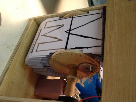
Now that I had the motors turning, it was time to construct the modules themselves! A workshop, some plans, and resourceful folk turned out the original versions. I won't go into too much detail about the dimensions until the later posts for the final design.![]() The card-holder are from 1.5 inch blanks found at Lowes. I was able to hand-drill 18 holes into two blanks. The cards themselves were carefully/poorly cut from a band-saw to some questionable dimensions. The initial prototype cards were printed with lovely permanent marker, it was sad that I had the best handwriting out of our group of three. The gray felt on top allowed us to adjust the amount of turns it took to display a single character.
The card-holder are from 1.5 inch blanks found at Lowes. I was able to hand-drill 18 holes into two blanks. The cards themselves were carefully/poorly cut from a band-saw to some questionable dimensions. The initial prototype cards were printed with lovely permanent marker, it was sad that I had the best handwriting out of our group of three. The gray felt on top allowed us to adjust the amount of turns it took to display a single character.Amazingly it worked, and it gave us the energy to quickly build one more prototype. We used a 3-inch hole saw, a protractor, a drill-press, and a awl to be able to make a better card-holder. I also went ahead and bought some stencils to give a cleaner look to the cards. See Video below.
At this point, my program was barely hobbling along. My background is EE and it's been a while... My only text entry was through the Serial Monitor on the Arduino IDE. It only accepted positional data so I had to calculate the positions for each module. Even worse, the mapping was off-set since it had a different amount of cards in the card holder.
Regardless, after about an hour, we exhausted the amount of two letter words we could display and stored them away in a text file to show the team!
Bonus Note: The prototype on the right was named Tiny. His original construction still exist and I use him constantly as a tester. The one of the left never got a name, he was taken apart in following couple of days to refine measurements.
Onward and upwards to prototype set of 16!
Split Flap Display
This display is being design and built for a local dance company as a set piece, exploring the concept of travel and transit.
 With the sensor now positioned, when the magnet passed by the switch it would 'make' a connection to ground. This 'ground' signal would let the Arduino know to stop the Stepper Motor and reset all it's positional data.
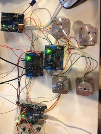 Now that I had the motors turning, it was time to construct the modules themselves! A workshop, some plans, and resourceful folk turned out the original versions. I won't go into too much detail about the dimensions until the later posts for the final design.
 The card-holder are from 1.5 inch blanks found at Lowes. I was able to hand-drill 18 holes into two blanks. The cards themselves were carefully/poorly cut from a band-saw to some questionable dimensions. The initial prototype cards were printed with lovely permanent marker, it was sad that I had the best handwriting out of our group of three. The gray felt on top allowed us to adjust the amount of turns it took to display a single character.