Matias N.
-
Derivative project started
05/25/2017 at 15:22 • 0 commentsI just wanted to let you know that I decided to give this a second take but removing more complex features, which ultimately required dealing with Android app development, which I'm not into.
Thus, I created BicycleCompanion MINI project, quite similar to this one but without Bluetooth and battery recharging (initially) and based on STM32F103. I plan to develop a custom PCB, which will allow for this device to be quite small.
-
Project put to sleep
02/01/2017 at 21:44 • 0 commentsThis update is just to let everyone know that I'm not currently pursuing this project anymore.
As I mentioned in the last project log, I sent the PCBs to manufacture. These actually arrived in the mail, but due to incredibly annoying customs beaurocratic requirements I decided to abandon the package after a few days.
At the same time, I decided to not work this anymore and focus in other non-hacking interests, work and life in general. Maybe someday I recover interest in this idea but I will leave this as-is for now.
Anyone willing to continue where I left is mostly welcome (and I may even chip in with help, guidance or ideas).
Thanks for your interest!
-
PCBs sent for fabrication!
09/18/2016 at 20:39 • 0 commentsAfter going over and over my PCB designs, fixing little things and making sure things would fit I finally decided to send them for fabrication.
Initially I considered using OSHpark, however I saw that international free shipping is without tracking. On the other hand, the cheapest trackable option was 50u$s!
I started looking at chinese fab houses and found PCBway. I saw that others were happy with the results (even though it seems PCBway gives credit for reviews, these seemed mostly honest). The important part: is is cheap! For the two PCBs (and with 5 copies of each) I was charged 10u$s for each design. Shipping was around 9u$s via HK post and with a 2u$s PayPal surcharge. The nice thing is you get a 5 u$s discount right after you register so the total was 28u$s.
Now I need to patiently wait for fabrication progress and shipping. This is also an experiment in bureaucracy since only recently importing has become a bit more relaxed to my country. I have yet to attest this.
Android App
In the meantime, while I could continue programming, I rather wait for the PCBs for that. Thus, I started looking at the possibilities for developing a companion app (I could name it "BicycleCompanionCompanion"). What I'm interested in is to see how likely is to receive turn-by-turn navigation directions from Android. It seems other products are capable of this but the Android world seems a bit closed, so I can't look at how they do it (for example, for the Pebble).
After doing some research it seems one possibility is to capture notifications, which contain driving directions. While Google Maps seems to do this, they recently change the notification system and it doesn't seem to be so easy. Although I have yet to look further into that. On the other hand, it seems that OsmAnd (which I used a lot) was extended for Pebble notifications. Since this App is open-source I was able to look at the code. Since there's already an Android app for the Pebble (which performs communication with the watch), OsmAnd seems to fire a specific intent for this. On the other hand, there seems to be a generic notification-based system.
I conclusion, I will probably start off attempting to capture OsmAnd instructions. In the worst case, I could try to add improved support for this and try to get it officially supported.
Finally, I wanted to say that I was a bit amazed at how the view count for this project spiked (from ~300 to ~2k in just a few days) after I uploaded Kicad renders of the board. It seems that everyone likes pretty pictures instead of my boring texts. Anyway, any comments are welcome!
-
Kicking kicad's tires
09/12/2016 at 02:34 • 0 commentsLast time I mentioned I wanted to get into designing a proper PCB for the device. So, since in the proto-board most things were functioning as expected. I decided to go ahead and start designing a PCB in Kicad.
First attempt
I must say I considerably underestimated the difficulty of cramming everything so tightly.
At the beginning I was aiming for a single two-sided PCB where I would mount: Teensy 3.1, OLED screen, battery charger, HC-05 bluetooth module, battery holder, four push-buttons and a power switch. After fighting a lot and going back and forth between different options, I realized it wasn't worth it.
Second attempt
So, I took a step back and decided I would use a simpler approach (after all, all of this started with "I'll just cram everything together with no PCB and solder everything via wires"). So, I started analyzing the main problems with the approach.
First, I realized the main problem was mounting the HC-05 bluetooth (bare module, since I have 3.3V already and does not make sense to regulate from 5V back to 3.3V) next to the Teensy, without wasting space. Since the module is for surface mounting, no other board (i.e. the carger) could be soldered using holes there. The second problem was that the charger module wasn't really intended for soldering to another PCB. Well, maybe it is possible, but the surface it occupies does not make sense. Finally, the 3V battery holder was just huge.
The solution
First, I decided to get rid of the battery holder. The 3V battery will be connected directly via wires (I can wrap the battery in insulating tape and maybe even try to solder wires to it).
Second, I realized the HC05 has almost the perfect size to be mounted on top of the Teensy with another PCB. While I initially attempted to design a PCB so that I would have something like a teensy "shield", I decided to simply do like a "lateral" breakout board. Then, the rest of the device would have a second PCB (where the teensy sits) and where the HC-05 breakout would connect. I could have used a similar design to that of the original breakout (pins on one short end), but this would block teensy's program button. With my approach, the button is reachable (with a little effort).
Finally, with this approach I managed to have the main PCB at 4x4cm, just the size of the battery.
While it took some extra effort, since I had to reassign a lot of pins on the Teensy to allow for more direct paths, I managed to even only use single-sided PCBs for both boards.
Behold the results.
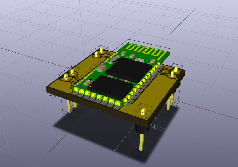
The HC-05 "shield":
![]()
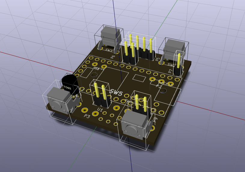
The base board:
![]()
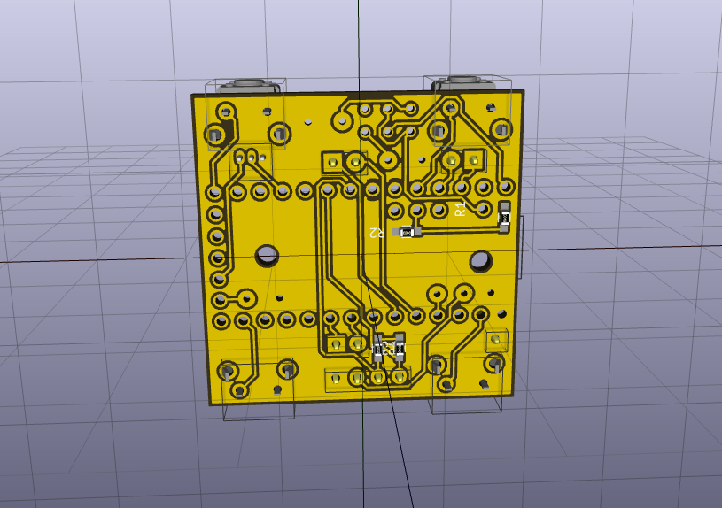
![]()
The four push-buttons would be on the top and bottom sides of the device (easier to handle while driving, I hope). I could not find an angled DPDT slide switch 3D model, so I hope it fits. The male pins connect to the HC05 board while the teensy sits in the middle. There are some large pads which are intended to solder the remaining components via wire: charger input and output, hall sensor, RTC battery.
Now, I need to see if I get this manufactured. I hope this PCB makes sense and I have not messed something up which makes it impossible to build.
-
Hardware mostly complete
09/08/2016 at 01:22 • 0 commentsI haven't been putting up new logs since I was actually concentrated on getting work done on the software side. Last week I got almost all hardware components (only missing the temperature sensor) I was planning for first version. With these, I have a mostly complete protoboard prototype (next log will include a picture detailing components). So, here's the situation now... Prepare for long post =)
Display
This is where I spent the majority of the effort last weeks. As I said, I'm using NuttX RTOS for development, since I wanted something nicer than simply coding everything using Arduino Libraries. This required adding support for several modules to NuttX, since Teensy 3.x was not fully supported. What was already there, though, was an I2C driver and a graphics subsystem (nxgraphics) which I started to use.
The first problem was due to the bizarre distribution of bits/bytes to rows/columns of the device. One would expect that, since the display is expected to be used in portrait mode, consecutive bits of conscutive bytes would correspond to columns of the display. However, it is exactly opposite. The problem is that the whole graphics system assumes the former layout and this requires the SSD1306 NuttX driver to map one layout to the other, performing quite wasteful computation. As an added annoyance, nxgraphics is not intended to be used for drawing to a memory or canvas and only later redrawing on demand. Generally, every drawing operation would trigger a transfer to the device. Since I'm using I2C, this is not really fast. Moreover, complex graphics usually require many primitive drawing operations, so I did not like this approach.
After lots of thinking and hitting my head against the wall, while balancing my idea of not reinventing the wheel and using already existing code with the fact that these issues where quite difficult to work with; I decided to code my own simple graphics system tailored to this particular layout and controlling myself the transfer to the device (I'm doing a full refresh after the frame is finished).
After lots of coding I finally managed to get it working. In retrospective I might re-visit this choice since I was considering alternative display hardware anyway. Mainly, I would like a bigger screen (maybe twice the size) and possibly with more than 1 bit-per-pixel. Dealing with bits can become quite tedious and, contrary to initial belief, quite inefficient since operations on many bits can be performed faster than on individual bits. One possibility here is to use a SSD1351 device, which is usually found as a 1.5'' color OLED device with 16bpp and 128x128 pixels. I like the fact that it is square and larger. At the moment, though, after the considerable effort, I will use the SSD1306 and re-visit these ideas when everything else is working as expected.
Odometer
Being something similar to a bicycle computer, I could not miss this feature so it was important to pass the proof of concept. For the odometer, I chose to use a latching hall-sensor, which means that it output a digital value which only transitions when the sensor encounters a magnetic field with opposite polarity than the previous one. Thus, this would work with two magnets (mounted with opposed polarity). This type of sensing allows for reducing false triggers of the sensor to almost zero and eliminates issues such as when the bicycle is stopped and the magnet is near the sensor, which would generate many false triggers.
To test the odometer, I mounted two magnets on a small plastic lid, and printed the state of the hall sensor. You can see this in the video below (please don't laugh at my crafting skills, this is extreme DIY)
You can see that the sensor does not change unless I perform another half rotation where the magnet with opposite polarity sits.
Battery / Power
As the device is supposed to be battery powered, I wanted to be able to support charging from the device itself. Also, I wanted to allow normal usage of the device while being charged. The device thus includes a TP4056 charger module, with the added DW01 protection IC. This means that when the device is powered, the battery is charged. Otherwise, battery power is used but controlled by the DW01, which disables the output if the battery is (extremely) drained at 2.4v. The charger also stops charging after reaching 4.2v. Since I'm using a 460mAh LiPo cell, 4.2v stop voltage is correct. However, 2.4v is really low and I would never want to get there. This means that is the device's responsibility of measuring battery voltage while discharging and turn of the teensy after maybe 3.4-3.6 volts or so.
The first problem here was that, since the charger board required replacing a SMD resistor which determines the charging current (by default at 1A, and which I set to below 400mAh for safety), after performing de- and re-soldering, the device did not seem to charge the battery (no LED turned on). After careful inspection, it seems that the re-soldering was not correct and the solder did not fully touch the tiny resistor. So, after a quick fix, the device was working correctly.
Second issue to be solved was to deal with powering the device while charging. While the carger includes a micro USB port, the Teensy already has one so I took the Vusb output of the teensy and sent that to the IN+ port of the carger. However, since the teensy cannot be powered by USB and battery at the same time, I cut the VIN-Vusb trace at the teensy as suggest. Finally, I've added a DPDT switch which allows to select "charge/off" or "on". In the "on" state, the battery powers the device and plugging the USB port does not bother (the device can be normally used and reflashed if necessary). In the "carge/off" state, if the cable is not plugged, the device is completely off. Otherwise, when the cable is plugged, charging starts and the device takes power from the USB port, not from the charger out, since this impedes fully charging the battery (parasite load).
Finally, my idea was to have charging state detection from the teensy (which was easy, simply connect Vusb to a digital pin, which is 5V tolerant) and also to measure battery voltage. Unexpectedly, the second step proved to be a bit difficult. One annoyance is that the DW01 protection IC does not like having a load (such as the resistor divider which is used to read the battery voltage) before the battery is plugged. In this case, when the battery is plugged, no output is generated. So, I had to always remove the resistor, plug the battery and re-plug the resistor... I figured that since the battery will be always plugged, I would not bother myself with this issue further. Moreover, as I wanted to monitor the battery not only during discharge (to display battery remaining) but also during charging. The latter seemed to be more involved since it is not just a matter of monitoring voltage, but would also require to measure current. While the charger module does this, it would require soldering a small cable directly to an IC pin, so I decided to leave this feature out. This means that the charger's LEDs (which indicate when charging is complete) will have to be exposed in the final device. Not so bad in the end.
Current work / thoughts
At the moment I'm considering acquiring the small temperature sensor, which is difficult to find here, since it has to be a 3.3v capable IC (such as TMP36). However, I like to be able to measure temperature from the device during riding. The remaining two components are: 3v coin battery for RTC backup and bluetooth HC05 module. I have both but have yet to include these to the protoboard, as space is getting tight (will probably buy a second one). I only found a CR2032 battery which is a bit big but which will do for the moment. The only difficulty here is that the VBat pin is inconveniently placed on the teensy and cannot be exposed via the breadboard easily. For the bluetooth module, my main concern is to test whether the total current of the device is within the teensy 3.1 limits of 100mAh. Anyway, I figure that eventually I can get the teensy 3.2, which has a 250mAh capable regulator and has the exact same chip as the 3.1.
After completing the protoboard build I will focus on finishing the graphic UI. I have thought (and already started to work on it) of a page-based UI, switchable from buttons. For example, one page would be the odometer, another one the time, another temperature and so on. Each page will have sub-pages to switch, for example, the speed units, and related measurements such as traveled distance. I will probably also include some combined data screen, although at 0.96'', there isn't much I would see (another reason for a larger screen). Finally, while complex configuration would be performed by the future companion Android app (via bluetooth), I decided to include some basic menu-based configuration on the device, to choose some settings which would be annoying to change only from the device.
The final thought was to consider actually building a PCB holding everything together (I was thinking of a small perfboard first) since I've looked at the prices at OSHpark and they seem amazingly cheap. The PCB would allow for a smaller package and cleaner build. But for this, I would like to be very sure of the hardware layout on the protoboard. However, I think that I will complete this soon.
Stay tuned for more project updates, and I hope the next one will include at least a nicer picture =D
-
Incoming components
08/23/2016 at 02:06 • 0 commentsThis will be another picture-less entry, but mainly to keep to rhythm of project logs.
Tomorrow I get the "smart" charger (integrated protection) and bluetooth (HC05) from the post-office (yay, another in-traffic biking experience). While I will not be able to play with this before the weekend (my laptop sleeps at work during week-days), good news is that I've found a pile of unused small LiPo cells at work. While some are a little puffed, some others are quite well. Most are 420mAh, a nice number at least for initial tests.
So, besides some other simple components (push-buttons, coin-battery) I think I have mostly what I will need for a while. I will have to wait for the hall sensor for another week, although I don't really need it to start some code for it.
Regarding the code, last weekend I've added ADC support to Teensy 3.x on NuttX and it seems to be working nicely. With this I will be able to measure the battery and detect charging/dis-charging condition.
Also, I've been thinking about the GUI and doing some crude sketches for guidance. As a test, I attempted to create a battery icon with different states (charging, critical, etc.) and for this I drew it on Gimp and converted it to XBM and the loaded it on the teensy. This worked great. I will probably try to sketch a logo/splash-screen for the device.
So next goal will probably be to complete a circuit on the protoboard featuring the charger and the battery and being able to detect charging and displaying charge level. For this I will probably deal with designing a GUI system based on pages (display-only for now, but including configuration screens later), which will change based on button presses.
On a final note, I created some repositories on GitLab for source-code and schematics, in case someone wants to check it out.
-
Success!
08/13/2016 at 23:10 • 0 commentsSo I2C required a bit more work to be completed, but I finally finished it. After doing so, I started playing with the NuttX OLED driver for the display I have. It seems this is some chinese alternative which is not exactly the same as SSD1306 so it required a few changes to the driver. Luckily, thanks to the awesome work in NuttX I had the display running in a matter of hours.
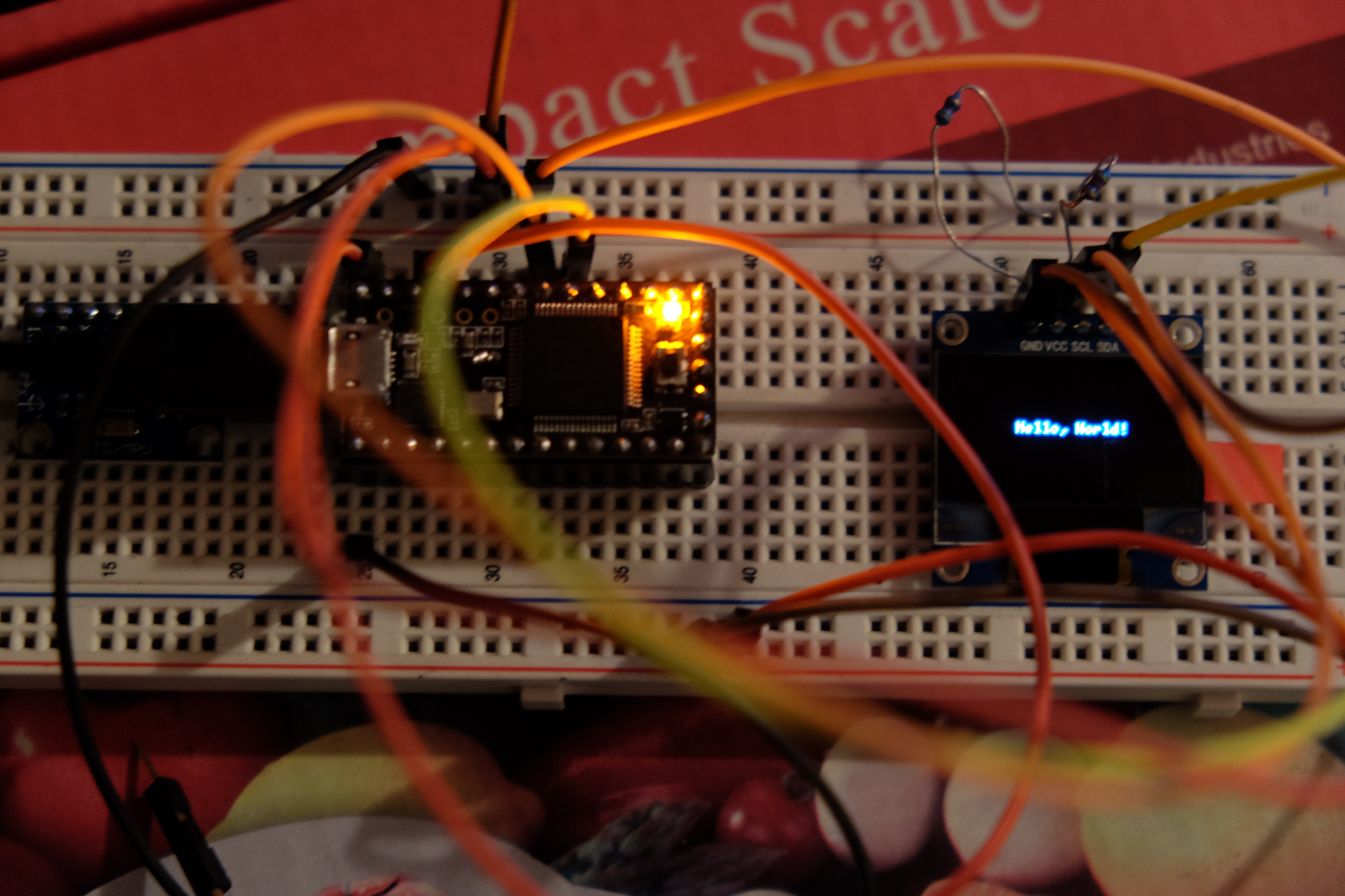
So, behold the proof of success:
![]()
Behind all that mess of cables you can see the Teensy 3.1 speaking to the OLED driver via I2C and running the "nxhello" example app from NuttX. In reality the text is quite crisp, but it is difficult to capture with a camera since the light is quite strong!
So, now next step is to create a custom app to start drawing custom things to the screen. I will probably display current time as a first test.
I must say that the update rate is quite slow using I2C, sadly the SPI capable displays were out of stock (actually, I bought the remaining two for the projects we have at work). Anyway, I don't think I will need a high update rate since while riding the bicycle, the eyes are not much time on anything else but the road.
I will probably start looking into the remaining components, such as the battery and charger. I think the teensy regular will be enough, so I don't need that for now. Maybe even some buttons to interact with the screen.
-
I2C and RTC: done
08/07/2016 at 15:52 • 0 commentsSo, I've developed the required RTC and I2C support for teensy 3.x into NuttX while waiting for the OLED.
The I2C code is always complicated to get right (I haven't managed to test it yet). Luckily the RTC is relatively simple and that is already working quite well (I would only need to finish the test using an actual 3v battery). At least the time survives across reboots when keeping teensy powered via USB.
On the other hand, the good news is that the OLED just arrived at the post office. The bad news, is that it is the wrong post office (FAIL), so it will require public transportation and leaving my bike for a day =(
Well, I hope that I'm not very far with having the teensy draw some stuff on the screen (to display the time would be great). After that, I guess I will start playing with GUI designs. That way I can at least put up some pictures/videos and stop the boring text-only logs.
So, if that goes well, I will most likely buy the remaining components to achieve v1.0 which would include battery+charger circuit+odometer (via hall sensor).
Which, now that I'm thinking, will require adding ADC support to teensy on NuttX. Oh well, at least others will benefit from it when I contribute it back into NuttX.
-
Waiting for the OLED
08/04/2016 at 02:36 • 0 commentsI've finally managed to buy an OLED display. It is supposed to be a bit bigger (1.3''), white color and I2C only. While the display is in transit, I've reconsidered not using NuttX.
For the initial tests, I only need I2C support, which is not available on NuttX for the teensy 3.1. However, I've actually coded this in the past (not for NuttX) but I've lost the code, so I will implement it and actually contribute it to NuttX at the same time. Luckily, I already understand I2C quite well (in contrast to SPI, which I thought I would use).
I will probably put the code (in progress) up in github soon, once I get I2C working.
Hopefully I can make some pretty graphics soon =)
-
First steps
07/31/2016 at 04:06 • 0 commentsSo I'm waiting for the damn OLED display to be in stock in local distributors, which seems quite difficult to achieve over here.
In the mean-time I've played a bit with my Teensy 3.1 which was gathering dust at work. I was considering using NuttX RTOS as the base code for the device, however some basic functionality is not supported (mainly the RTC code). So, instead of over-complicating things, I will simply use the teensyduino IDE (Arduino IDE with Teensy support) until I really need something more complex (I'm abiding to KISS here, as an anti-procrastination measure).
My first goal is to be able to play with the OLED display in terms of interface design. After playing a bit with a simple smartwatch (which, co-incidentally has an OLED screen, but half size than the one I'm looking for) on my bike I've found some aspects I'm interested in:
- The screen should stay on. Seems obvious, but my smart(dumb)watch requires a key-press and will stay on for up to 15 seconds
- The screen should accommodate sufficient info all at once. My smartwatch (and other cheap bicycle computers, from what I've seen) requires key-presses to change screens (distance, time, speed, etc.). I would like to design a simple and informative screen which should accommodate things like speed as a gauge bar (I don't think reading a number makes sense here), distance as a small number (you don't need to read this while driving very fast), battery as a small icon, elapsed and current time, etc.
After I manage to find the OLED and this seems feasible, I will try to build a first version reading a standard magnetic sensor and having a LiPo battery + charger. Hopefully this should not take much more time.
Teensy Bicycle Computer
Similar to a bicycle computer but hackable, including different sensors and potentially connecting to and Android device via bluetooth