 Ianislav Trendafilov
-
I2C on OPT8241
08/24/2016 at 23:41 • 0 commentsI have connected the opt8241 sensor over I2C. I have disabled sensor clock by setting MCLCK to 0. Power consumption of adapter board is ~1.8 mA. Then I have sent the i2c commands. Command output :
 # i2cdetect 2
WARNING! This program can confuse your I2C bus, cause data loss and worse!
I will probe file /dev/i2c-2.
I will probe address range 0x03-0x77.
Continue? [Y/n]
     0  1  2  3  4  5  6  7  8  9  a  b  c  d  e  f
00:          -- -- -- -- -- -- -- -- -- -- -- -- --
10: -- -- -- -- -- -- -- -- -- -- -- -- -- -- -- --
20: -- -- -- -- -- -- -- -- -- -- -- -- -- -- -- --
30: -- -- -- -- -- -- -- -- -- -- -- -- -- -- -- --
40: -- -- -- -- -- -- -- -- -- -- -- -- -- -- -- --
50: -- -- -- -- -- -- -- -- 58 -- -- -- -- -- -- --
60: -- -- -- -- -- -- -- -- -- -- -- -- -- -- -- --
70: -- -- -- -- -- -- -- --

 # i2cdump 2 0x58
No size specified (using byte-data access)
WARNING! This program can confuse your I2C bus, cause data loss and worse!
I will probe file /dev/i2c-2, address 0x58, mode byte
Continue? [Y/n]
     0  1  2  3  4  5  6  7  8  9  a  b  c  d  e  f    0123456789abcdef
00: 00 00 00 00 00 00 00 00 00 00 00 00 00 00 00 9a    ...............?
10: 88 10 00 00 00 00 00 00 00 00 01 00 00 00 00 00    ??........?.....
20: 00 9f 20 00 00 00 00 00 00 80 00 00 00 00 00 00    .? ......?......
30: 00 d0 00 00 00 00 00 00 00 00 00 00 00 00 00 00    .?..............
40: 00 00 00 00 0e 00 00 00 00 00 00 00 00 01 00 00    ....?........?..
50: 00 00 00 00 00 80 00 00 00 00 00 01 00 00 06 f0    .....?.....?..??
60: 10 54 f4 4c 00 00 00 00 00 00 00 00 44 00 00 00    ?T?L........D...
70: 00 00 00 00 00 00 00 00 00 00 00 00 00 00 00 00    ................
80: 00 80 a0 44 00 00 00 08 01 09 01 09 a1 00 53 08    .??D...??????.S?
90: 00 00 08 00 00 00 03 d0 00 00 81 00 00 03 f0 00    ..?...??..?..??.
a0: 00 81 00 00 00 00 00 00 00 d2 52 00 00 81 d2 52    .?.......?R..??R
b0: 00 00 81 00 00 00 00 00 00 00 00 00 00 00 00 00    ..?.............
c0: 00 00 00 00 00 00 00 00 00 00 00 00 00 00 00 00    ................
d0: 00 53 5b 00 00 81 01 00 00 00 00 00 00 00 00 00    .S[..??.........
e0: 00 00 00 00 00 00 00 00 00 00 00 00 00 00 00 00    ................
f0: 00 00 00 00 00 00 00 00 00 00 00 00 00 00 00 00    ................
As you can see, sensor has I2C address of 0x58. I have tried warming the sensor thus increasing temperature. Output from i2cdump has not changed.
Next I have tried write operations. Script I am using is:
for i in `seq 0 255`
do
     address=$(printf "0x%.2x" $i);
     i2cset 2 0x58 $address 0x7f;
done;
It requires user input, to execute commands, which is good for step-by-step interaction. If you wish to overwrite full memory, you have to add "-y" argument to i2cset command.First I have tried writing 0x0A. To simplify output I am showing output only when I write a full row (like 0x00 to 0x0F, then 0x10 to 0x1F and so on). Writing on row 0x40 have changed output on row 0x20. I should investigate this in the future. Power consumption on all logic have remain 1.8mA.
      0  1  2  3  4  5  6  7  8  9  a  b  c  d  e  f    0123456789abcdef
-00: 0a 00 00 00 00 00 00 00 00 00 00 00 00 00 00 9a    ?..............?
+00: 0a 0a 0a 00 00 00 00 00 0a 00 0a 0a 0a 0a 0a 0a    ???.....?.??????

-10: 88 10 00 00 00 00 00 00 00 00 01 00 00 00 00 00    ??........?.....
+10: 0a 0a 0a 0a 0a 0a 0a 0a 0a 0a 0b 0a 0a 0a 00 0a    ??????????????.?

-20: 00 9f 20 00 00 00 00 00 00 80 00 00 00 00 00 00    .? ......?......
+20: 0a 0a 0a 00 0a 0a 0a 0a 02 8a 0a 0a 0a 0a 0a 0a    ???.????????????

-30: 00 d0 00 00 00 00 00 00 00 00 00 00 00 00 00 00    .?..............
+30: 0a d0 0a 0a 0a 0a 0a 00 0a 0a 0a 00 00 00 00 00    ???????.???.....

-20: 0a 0a 0a 00 0a 0a 0a 0a 02 8a 0a 0a 0a 0a 0a 0a    ???.????????????
+20: 0a 0a 0a 00 0a 0a 0a 0a 02 0a 0a 0a 0a 0a 0a 0a    ???.????????????
 30: 0a d0 0a 0a 0a 0a 0a 00 0a 0a 0a 00 00 00 00 00    ???????.???.....
-40: 00 00 00 00 0e 00 00 00 00 00 00 00 00 01 00 00    ....?........?..
+40: 0a 0a 0a 00 0e 00 00 00 00 00 00 00 00 0b 00 00    ???.?........?..

-50: 00 00 00 00 00 80 00 00 00 00 00 01 00 00 06 f0    .....?.....?..??
+50: 00 00 00 00 00 80 00 00 00 00 00 01 0a 0a 0a 0a    .....?.....?????

-60: 10 54 f4 4c 00 00 00 00 00 00 00 00 44 00 00 00    ?T?L........D...
+60: 0a 0a 0a 0a 0a 0a 0a 0a 00 0a 0a 0a 0a 0a 0a 0a    ????????.???????

-70: 00 00 00 00 00 00 00 00 00 00 00 00 00 00 00 00    ................
+70: 0a 0a 0a 0a 0a 00 00 00 00 00 00 00 00 00 00 00    ?????...........

-80: 00 80 a0 44 00 00 00 08 01 09 01 09 a1 00 53 08    .??D...??????.S?
+80: 0b 0a 0a 0a 0a 0a 0a 0a 0a 0a 0a 0a 0a 0a 0a 0a    ????????????????

-90: 00 00 08 00 00 00 03 d0 00 00 81 00 00 03 f0 00    ..?...??..?..??.
+90: 0a 0a 0a 0a 00 00 0a 0a 0a 0a 0a 00 00 0a 0a 0a    ????..?????..???

-a0: 00 81 00 00 00 00 00 00 00 d2 52 00 00 81 d2 52    .?.......?R..??R
+a0: 0a 0a 00 00 0a 0a 0a 0a 0a 0a 0a 0a 0a 0a 0a 0a    ??..????????????

-b0: 00 00 81 00 00 00 00 00 00 00 00 00 00 00 00 00    ..?.............
+b0: 0a 0a 0a 0a 0a 0a 0a 0a 0a 0a 0a 0a 0a 0a 0a 0a    ????????????????

-c0: 00 00 00 00 00 00 00 00 00 00 00 00 00 00 00 00    ................
+c0: 0a 0a 0a 0a 0a 0a 0a 0a 0a 0a 0a 0a 0a 0a 0a 0a    ????????????????

-d0: 00 53 5b 00 00 81 01 00 00 00 00 00 00 00 00 00    .S[..??.........
+d0: 0a 0a 0a 0a 0a 0a 0a 00 00 00 00 00 00 00 00 00    ???????.........
After that I wrote 7F to all addresses. Power consumption is now 47mA
      0  1  2  3  4  5  6  7  8  9  a  b  c  d  e  f    0123456789abcdef
-00: 0a 0a 0a 00 00 00 00 00 0a 00 0a 0a 0a 0a 0a 0a    ???.....?.??????
-10: 0a 0a 0a 0a 0a 0a 0a 0a 0a 0a 0b 0a 0a 0a 00 0a    ??????????????.?
-20: 0a 0a 0a 00 0a 0a 0a 0a 02 0a 0a 0a 0a 0a 0a 0a    ???.????????????
-30: 0a d0 0a 0a 0a 0a 0a 00 0a 0a 0a 00 00 00 00 00    ???????.???.....
-40: 0a 0a 0a 00 0e 00 00 00 00 00 00 00 00 0b 00 00    ???.?........?..
-50: 00 00 00 00 00 80 00 00 00 00 00 01 0a 0a 0a 0a    .....?.....?????
-60: 0a 0a 0a 0a 0a 0a 0a 0a 00 0a 0a 0a 0a 0a 0a 0a    ????????.???????
-70: 0a 0a 0a 0a 0a 00 00 00 00 00 00 00 00 00 00 00    ?????...........
-80: 0b 0a 0a 0a 0a 0a 0a 0a 0a 0a 0a 0a 0a 0a 0a 0a    ????????????????
-90: 0a 0a 0a 0a 00 00 0a 0a 0a 0a 0a 00 00 0a 0a 0a    ????..?????..???
-a0: 0a 0a 00 00 0a 0a 0a 0a 0a 0a 0a 0a 0a 0a 0a 0a    ??..????????????
-b0: 0a 0a 0a 0a 0a 0a 0a 0a 0a 0a 0a 0a 0a 0a 0a 0a    ????????????????
-c0: 0a 0a 0a 0a 0a 0a 0a 0a 0a 0a 0a 0a 0a 0a 0a 0a    ????????????????
-d0: 0a 0a 0a 0a 0a 0a 0a 00 00 00 00 00 00 00 00 00    ???????.........
+00: 00 7f 7f 00 00 00 00 00 7f 00 7f 7f 7f 7f 7f 7f    .??.....?.??????
+10: 7f 7f 7f 7f 7f 7f 7f 7f 7f 7f 7f 7f 7f 7f 00 7f    ??????????????.?
+20: 7f 7f 7f 00 7f 7f 7f 7f 7f 7f 7f 7f 7f 7f 7f 7f    ???.????????????
+30: 7f d0 0f 7f 7f 7f 7f 00 7f 7f 7f 00 00 00 00 00    ???????.???.....
+40: 7f 7f 7f 00 7f 7f 7f 7f 7f 7f 7f 7f 1f 7f 00 00    ???.??????????..
+50: 00 00 00 00 00 80 00 00 00 00 00 01 7f 00 06 f0    .....?.....??.??
+60: 10 54 f4 4c 00 00 00 00 00 00 00 00 44 00 00 00    ?T?L........D...
+70: 00 00 00 00 00 00 00 00 00 00 00 00 00 00 00 00    ................
+80: 00 80 a0 44 00 00 00 08 01 09 01 09 a1 00 53 08    .??D...??????.S?
+90: 00 00 08 00 00 00 03 d0 00 00 81 00 00 03 f0 00    ..?...??..?..??.
+a0: 00 81 00 00 00 00 00 00 00 d2 52 00 00 81 d2 52    .?.......?R..??R
+b0: 00 00 81 00 00 00 00 00 00 00 00 00 00 00 00 00    ..?.............
+c0: 00 00 00 00 00 00 00 00 00 00 00 00 00 00 00 00    ................
+d0: 00 53 5b 00 00 81 01 00 00 00 00 00 00 00 00 00    .S[..??.........
 e0: 00 00 00 00 00 00 00 00 00 00 00 00 00 00 00 00    ................
 f0: 00 00 00 00 00 00 00 00 00 00 00 00 00 00 00 00    ................
I have then executed the 7F write, one address on a time and found power consumption increases when writing to address 0x08. I then tried writing single bit values at a time (0x01, 0x02, 0x04, 0x08, 0x10, 0x20, 0x40, 0x80). Power consumption changes only when writing 0x04. To test that I have wrote !(0x04)=0xFB. There was a bit of power increase (suggesting some logic is wired. I have found that this is value 0x80. To test that I have write value !(0x80&0x04)=0x7B . (My multimeter is 22000 count and has microAmp range. All power consumption values are rounded for representation purposes)
i2cset -y 2 0x58 0x08 0x00 # Power consumption is 1.8mA
i2cset -y 2 0x58 0x08 0xfb # Power consumption is 1.9mA
i2cset -y 2 0x58 0x08 0x04 # Power consumption is 42mA
i2cset -y 2 0x58 0x08 0x80 # Power consumption is 1.9mA
i2cset -y 2 0x58 0x08 0x7b # Power consumption is 1.8mA
At the end - it seems that writing 0x04 to address 0x08 on device 0x58 is enabling opt8241 logic. To verify that I will have to write the FPGA data acquisition logic IP next weeks.
-
Playing with I2C bus
08/22/2016 at 20:58 • 0 commentsToday I was able to communicate with a simple I2C slave that I have created for proof-of-concept. What you need (step-by-step instructions):
1. Enable i2c-gpio in kernel
2. Compile and load i2c-gpio-param kernel module from https://github.com/kadamski/i2c-gpio-param
3. Create a Parallel IO bus in FPGA using Qsys . Pin type should be BiDirectional
4. Compile and upload your new RBF. Then load using device-tree overlay as it was described in older project logs here.
5. Create a new overlay and load it on top of other one. In my case (as a diff from Quartus output):
/dts-v1/;
/ {
        fragment@0 {
                target-path = "/clocks";
                #address-cells = <1>;
                #size-cells = <1>;

                clk_0: clk_0 {};
        };

        fragment@1 {
                target-path = "/sopc@0";
                #address-cells = <2>;
                #size-cells = <1>;

                fpga_mgr0: fpga_mgr@ff706000 {};
                base_fpga_region: base_fpga_region@0xff200000 {};
                hps_0_arm_gic_0: intc@0xfffed000 {};
        };

        fragment@2 {
                #address-cells = <2>;
                #size-cells = <1>;
                target-path = "/sopc@0/bridge@0xc0000000";
                __overlay__ {
                        #address-cells = <2>;
                        #size-cells = <1>;
                        ranges =
                                <0x00000000 0x00000000 0xc0000000 0x00010000>,
                                <0x00000001 0x00020000 0xff220000 0x00000008>,
                                <0x00000001 0x00010000 0xff210000 0x00000008>,
                                <0x00000001 0x00010008 0xff210008 0x00000008>,
                                <0x00000001 0x00010080 0xff210080 0x00000010>,
                                <0x00000001 0x000100c0 0xff2100c0 0x00000010>,
                                <0x00000001 0x00010040 0xff210040 0x00000020>;

                        gpio1h_pio: gpio@0x100010040 {
                                compatible = "altr,pio-16.0", "altr,pio-1.0";
                                reg = <0x00000001 0x00010040 0x00000020>;
                                interrupt-parent = <&hps_0_arm_gic_0>;
                                interrupts = <0 42 1>;
                                clocks = <&clk_0>;
                                altr,gpio-bank-width = <4>;     /* embeddedsw.dts.params.altr,gpio-bank-width type NUMBER */
                                altr,interrupt-type = <3>;      /* embeddedsw.dts.params.altr,interrupt-type type NUMBER */
                                altr,interrupt_type = <3>;      /* embeddedsw.dts.params.altr,interrupt_type type NUMBER */
                                edge_type = <2>;        /* embeddedsw.dts.params.edge_type type NUMBER */
                                level_trigger = <0>;    /* embeddedsw.dts.params.level_trigger type NUMBER */
                                resetvalue = <0>;       /* embeddedsw.dts.params.resetvalue type NUMBER */
                                #gpio-cells = <2>;
                                gpio-controller;
                        }; //end gpio@0x100010040 (gpio1h_pio)
                };
        };
};
6. (optional) You can validate it actually works by using gpio bit-banging with: this script#!/bin/sh DIPSW_COUNT=4 DIPSW_BASE=363 DIPSW_END=$((${DIPSW_BASE} + ${DIPSW_COUNT} - 1)) BTNSW_COUNT=2 BTNSW_BASE=331 BTNSW_END=$((${BTNSW_BASE} + ${BTNSW_COUNT} - 1)) LED_COUNT=8 LED_BASE=395 LED_END=$((${LED_BASE} + ${LED_COUNT} - 1)) function load_rbf { if [ ! -d /config/device-tree/overlays/load_rbf ] then echo "Mounting configfs" mkdir -p /config mount -t configfs configfs /config mkdir /config/device-tree/overlays/load_rbf sleep 1 echo "Load RBF binary" # cat /root/load_rbf_only.dtbo > /config/device-tree/overlays/load_rbf/dtbo cat /root/load_3dtof.dtbo > /config/device-tree/overlays/load_rbf/dtbo fi } function gpio_enable { if [ ! -d /sys/class/gpio/gpio$1 ] then echo "Enabling GPIO $1" echo $1 > /sys/class/gpio/export fi } function gpio_direction { gpio_enable $1 if [ "x$2" != "x$(cat /sys/class/gpio/gpio$1/direction)" ] then echo "Enable GPIO $1 as ${2}put" echo $2 > /sys/class/gpio/gpio$1/direction fi } function gpio_in { gpio_direction $i "in" } function gpio_out { gpio_direction $i "out" } load_rbf for i in $(seq ${DIPSW_BASE} ${DIPSW_END}) do gpio_in $i done; for i in $(seq ${BTNSW_BASE} ${BTNSW_END}) do gpio_in $i done; for i in $(seq ${LED_BASE} ${LED_END}) do gpio_out $i done;7. Add a new i2c device with command:
# 2 = bus id
# 333 = GPIO1[34] , 335 = GPIO1[35]
# 500 = 500usec delay or equal to 2kHz
# 1000 = 1ms timeout
# 0 0 0 = non open drain
echo 2 333 334 500 1000 0 0 0 > /sys/class/i2c-gpio/add_bus
8. Connect an I2C Slave device. I have used a MSP430F5529LP board and created that code (modifying TI examples):#include "driverlib.h" #define SLAVE_ADDRESS 0x3F uint8_t transmitData; void main(void) { WDT_A_hold(WDT_A_BASE); // Disable watchdog //Assign I2C pins to USCI_B0 GPIO_setAsPeripheralModuleFunctionInputPin( GPIO_PORT_P4, GPIO_PIN1 + GPIO_PIN2); //Initialize I2C as a slave device USCI_B_I2C_initSlave(USCI_B1_BASE, SLAVE_ADDRESS); //Enable I2C Module to start operations USCI_B_I2C_enable(USCI_B1_BASE); //Set in transmit mode USCI_B_I2C_setMode(USCI_B1_BASE, USCI_B_I2C_TRANSMIT_MODE); //Initialize transmit data buffer transmitData = 0xAB; while (1) { // Poll for start while (0x00 == USCI_B_I2C_getInterruptStatus(USCI_B1_BASE, USCI_B_I2C_START_INTERRUPT)) { ; } // Poll for transmit flag while (0x00 == USCI_B_I2C_getInterruptStatus(USCI_B1_BASE, USCI_B_I2C_TRANSMIT_INTERRUPT)) { ; } //Transmit data USCI_B_I2C_slavePutData(USCI_B1_BASE, transmitData); // Increment TXData //transmitData++; // disable to validate transmission line for errors :) // Poll will STOP is received while (0x00 == USCI_B_I2C_getInterruptStatus(USCI_B1_BASE, USCI_B_I2C_STOP_INTERRUPT)) { ; } } }9. You should add pull-up resistors to the bus like http://quick2wire.com/wp-content/uploads/2012/05/image00.png (I'm too lazy to create a schematic for that)
10. Test with:# i2cget 2 0x3F WARNING! This program can confuse your I2C bus, cause data loss and worse! I will read from device file /dev/i2c-2, chip address 0x48, current data address, using read byte. Continue? [Y/n] 0xab
11. You can look for your device on the bus with:# i2cdetect 2 WARNING! This program can confuse your I2C bus, cause data loss and worse! I will probe file /dev/i2c-2. I will probe address range 0x03-0x77. Continue? [Y/n] 0 1 2 3 4 5 6 7 8 9 a b c d e f 00: -- -- -- -- -- -- -- -- -- -- -- -- -- 10: -- -- -- -- -- -- -- -- -- -- -- -- -- -- -- -- 20: -- -- -- -- -- -- -- -- -- -- -- -- -- -- -- -- 30: -- -- -- -- -- -- -- -- -- -- -- -- -- -- -- 3f 40: -- -- -- -- -- -- -- -- -- -- -- -- -- -- -- -- 50: -- -- -- -- -- -- -- -- -- -- -- -- -- -- -- -- 60: -- -- -- -- -- -- -- -- -- -- -- -- -- -- -- -- 70: -- -- -- -- -- -- -- --I will create a GitHub repo in the future with all that code
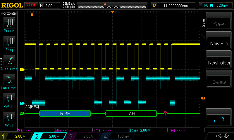
Results on data bus:
![]()
-
Custom OPT8241 adapter board have been assembled
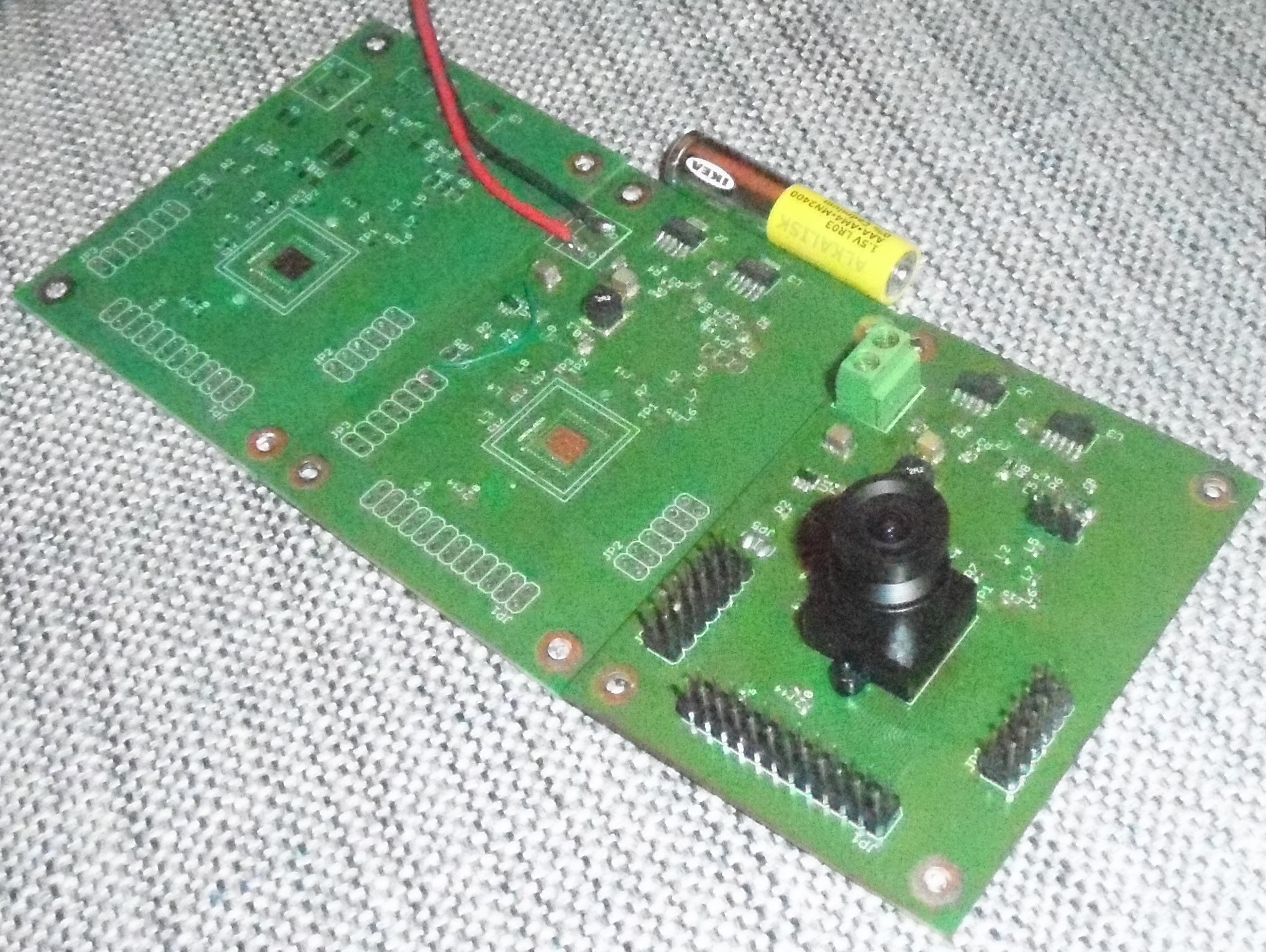
08/19/2016 at 17:43 • 0 commentsCustom OPT8241 adapter board have been assembled. Those ф=220um BGA packages are hell to assemble. I have integrated all power supplies on board, so I can run it on single 5V adapter with FPGA board.
![]()
Left to right - unassembled board, board for power supply tests and fully assembled board. Compared to an AAA battery.
![My PRECIOUS!!!!]()
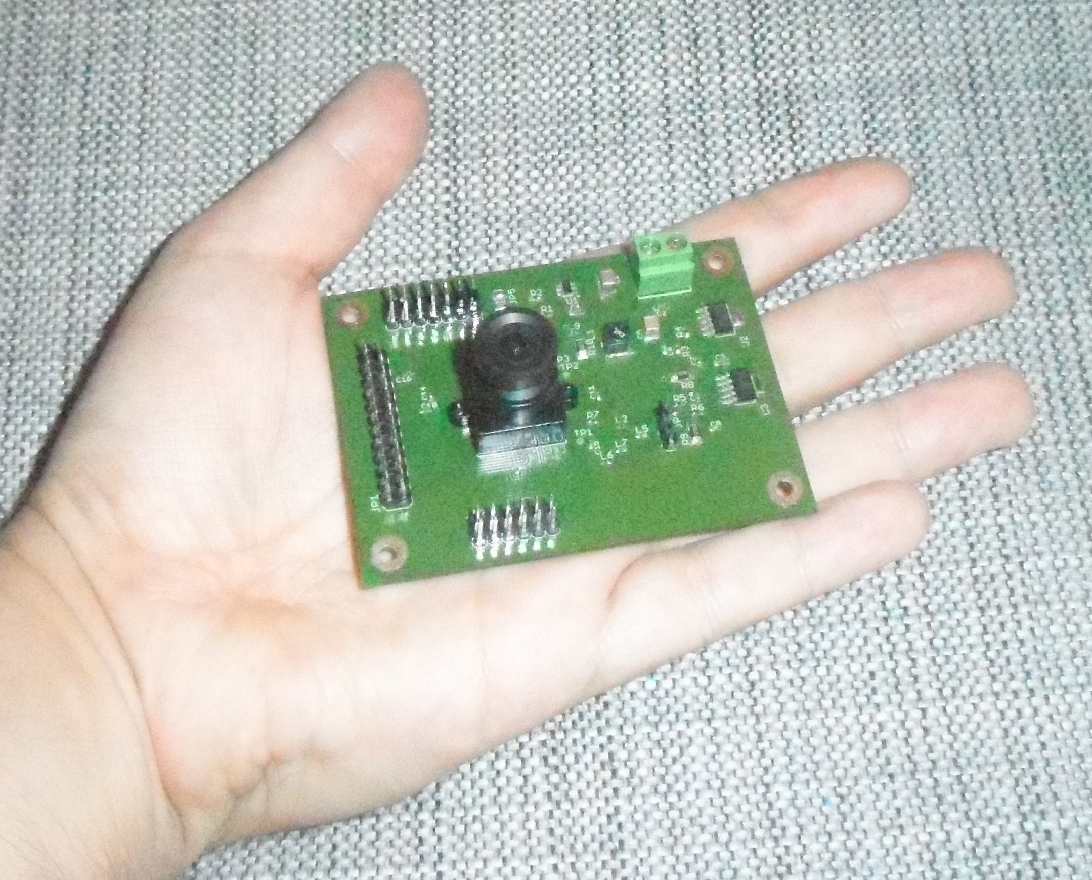
My PRECIOUS!!!!
Next step is connect to DE0-Nano-SoC. OPT8241 i2c register map is not public thought :( (but I have a backup plan)
-
"(blink) (blink)" a.k.a "Hello, World!" of hardware
08/17/2016 at 08:25 • 0 commentsFollowing the guide from https://rocketboards.org/foswiki/view/Documentation/EmbeddedLinuxBeginnerSGuide , I have managed to load fpga rbf and blink leds using user-space program in chapter 11. Custom kernel driver in chapter 12 is also working.
It took a couple of days, as I had to fix hps_common_board_info.xml and soc_system.sopcinfo. New device-tree is compatible with kernel 4.6.5. I also fixed the annoying lag jitter by setting ethenet ex delays to values from kernel dts subsystem. You can find all files in Project files -> soc_system_tree.zip. Included you may find the final soc_system.dts, that you may convert to dtb and use directly.
With new device-tree overlays, development process is very simplified. Loading soc_system.rbf and/or adding new devices to device-tree is quite simple:
/*
 Example device-tree overlay. Load soc_system.rbf from /lib/firmware
*/
/dts-v1/;
/ {
	fragment@0 {
		target-path = "/sopc@0/base_fpga_region@0xff200000";
		#address-cells = <2>;
		#size-cells = <1>;
		__overlay__ {
			#address-cells = <2>;
			#size-cells = <1>;
			firmware-name = "soc_system.rbf";
		};
	};
};
mkdir -p /config && mount -t configfs configfs /config && mkdir /config/device-tree/overlays/foo dtc -I dts -O dtb -o test.dtbo overlay.dts cat test.dtbo > /config/device-tree/overlays/foo/dtbo -
Gentoo Linux running on DE0-Nano-SoC
08/09/2016 at 12:06 • 0 commentsInstalling Gentoo Linux on DE0-Nano-SoC. I have used https://eewiki.net/display/linuxonarm/DE0-Nano-SoC+Kit as reference. I made modifications to use newer u-boot and replaced the Debian with Gentoo. I only had to update /etc/inittab speed and remove root password from /etc/shadow.
System is up and running.
3D-ToF scanner
Project uses OPT8241 3D-ToF sensor, CycloneV FPGA with HPS and Linux OS